WO2015129357A1 - Machine de travail à moteur - Google Patents
Machine de travail à moteur Download PDFInfo
- Publication number
- WO2015129357A1 WO2015129357A1 PCT/JP2015/051862 JP2015051862W WO2015129357A1 WO 2015129357 A1 WO2015129357 A1 WO 2015129357A1 JP 2015051862 W JP2015051862 W JP 2015051862W WO 2015129357 A1 WO2015129357 A1 WO 2015129357A1
- Authority
- WO
- WIPO (PCT)
- Prior art keywords
- engine
- shaft
- starter
- crankshaft
- working machine
- Prior art date
- Legal status (The legal status is an assumption and is not a legal conclusion. Google has not performed a legal analysis and makes no representation as to the accuracy of the status listed.)
- Ceased
Links
Images


Classifications
-
- F—MECHANICAL ENGINEERING; LIGHTING; HEATING; WEAPONS; BLASTING
- F02—COMBUSTION ENGINES; HOT-GAS OR COMBUSTION-PRODUCT ENGINE PLANTS
- F02N—STARTING OF COMBUSTION ENGINES; STARTING AIDS FOR SUCH ENGINES, NOT OTHERWISE PROVIDED FOR
- F02N3/00—Other muscle-operated starting apparatus
- F02N3/02—Other muscle-operated starting apparatus having pull-cords
-
- A—HUMAN NECESSITIES
- A01—AGRICULTURE; FORESTRY; ANIMAL HUSBANDRY; HUNTING; TRAPPING; FISHING
- A01D—HARVESTING; MOWING
- A01D34/00—Mowers; Mowing apparatus of harvesters
- A01D34/01—Mowers; Mowing apparatus of harvesters characterised by features relating to the type of cutting apparatus
- A01D34/412—Mowers; Mowing apparatus of harvesters characterised by features relating to the type of cutting apparatus having rotating cutters
- A01D34/63—Mowers; Mowing apparatus of harvesters characterised by features relating to the type of cutting apparatus having rotating cutters having cutters rotating about a vertical axis
- A01D34/67—Mowers; Mowing apparatus of harvesters characterised by features relating to the type of cutting apparatus having rotating cutters having cutters rotating about a vertical axis hand-guided by a walking operator
- A01D34/68—Mowers; Mowing apparatus of harvesters characterised by features relating to the type of cutting apparatus having rotating cutters having cutters rotating about a vertical axis hand-guided by a walking operator with motor driven cutters or wheels
- A01D34/6806—Driving mechanisms
- A01D34/6818—Motor starting mechanisms
-
- F—MECHANICAL ENGINEERING; LIGHTING; HEATING; WEAPONS; BLASTING
- F02—COMBUSTION ENGINES; HOT-GAS OR COMBUSTION-PRODUCT ENGINE PLANTS
- F02N—STARTING OF COMBUSTION ENGINES; STARTING AIDS FOR SUCH ENGINES, NOT OTHERWISE PROVIDED FOR
- F02N11/00—Starting of engines by means of electric motors
- F02N11/12—Starting of engines by means of mobile, e.g. portable, starting sets
-
- F—MECHANICAL ENGINEERING; LIGHTING; HEATING; WEAPONS; BLASTING
- F02—COMBUSTION ENGINES; HOT-GAS OR COMBUSTION-PRODUCT ENGINE PLANTS
- F02N—STARTING OF COMBUSTION ENGINES; STARTING AIDS FOR SUCH ENGINES, NOT OTHERWISE PROVIDED FOR
- F02N5/00—Starting apparatus having mechanical power storage
- F02N5/02—Starting apparatus having mechanical power storage of spring type
Definitions
- the present invention relates to the structure of an engine working machine using a small engine, such as a brush cutter.
- a small working engine is used as a power source for portable working machines such as brush cutters, blowers, chainsaws, power cutters, and the like that are carried and used by workers. *
- FIG. 10A is a side view showing a configuration of the brush cutter 310
- FIG. 10B is an enlarged partial cross-sectional view of a power unit provided on the rear end side.
- FIG. 10A shows a form when the brush cutter 310 is installed on the ground.
- the vertical direction means the vertical direction in this case, and the left side in this figure is the front side and the right side. Is the rear. *
- a power unit 330 for driving the cutting blade 11 is provided on the rear end (one end) side of the operation rod 20 elongated in the front-rear direction, and the cutting blade rotating on the tip (other end) side.
- a blade 11 is provided.
- a small and light two-cycle air-cooled engine 340 is used as a power source in the power unit 330.
- a transmission shaft (not shown) which is coaxial with the operation rod 20 and is connected to the crankshaft of the engine 340 and a centrifugal clutch (both not shown). When the rotational speed of the crankshaft increases and the centrifugal clutch is connected, the transmission shaft rotates by the engine 340.
- an intake port and an exhaust port are respectively provided on the left and right sides (the front side and the other side in FIG. 10A) of the engine 340, and a carburetor (not shown) and an air cleaner are provided on the intake port side. 50 and mufflers (not shown) are respectively connected to the exhaust port side.
- fuel mixed gasoline
- fuel is also supplied, whereby an air-fuel mixture is generated and supplied to the engine 340.
- the fuel is stored in a fuel tank 60 fixed to the lower part of the engine 340, and is guided from the fuel tank 60 to a carburetor through a tube.
- An operator can remove the tank cap 61 provided in the fuel tank 60 and supply fuel into the fuel tank 60.
- fuel is sucked up from the fuel tank 60 side to the carburetor side by the negative pressure generated during intake.
- a protective cover (stand) 15 made of a resin material that supports the brush cutter 30 when it is installed on the ground and covers the lower side of the fuel tank 60 is mounted under the fuel tank 60. . *
- a manual starter (recoil starter) 341 for starting the engine 340 by manually rotating the crankshaft is provided.
- a rope is connected to a reel connected to the crankshaft via a one-way clutch, and the operator pulls the rope strongly to force against the pressure at the time of piston compression in the engine 340.
- the crankshaft can be rotated. Further, after the rope is pulled, the rope is automatically rewound to the reel side by a spring. For this reason, even when the engine 340 does not start by such a single operation, the operator can repeatedly perform the operation of pulling the rope until the engine 340 starts.
- the carburetor is also provided with a choke lever that temporarily enriches the air-fuel mixture by its operation.
- the choke lever is operated (the starter 341 is operated with the air-fuel mixture turned on to start the engine 340, and the operation of the choke lever is released after the engine 340 is started (
- the engine 341 can be operated with the air / fuel mixture at a normal concentration.
- the starter 341 having the above configuration is light because it is a very simple configuration, and even if the starter 341 is used, the weight of the entire trimmer 310 is small, and the trimmer 310 is lightweight. It can be.
- the choke lever is also equipped in a normal carburetor, and the mechanism related to the choke lever occupies a small weight. For this reason, the brush cutter 310 having the above-described configuration can be reduced in weight. Further, as described above, since the operation of the starter 341 is very simple, the engine 340 can be easily started using this, and work using the brush cutter 310 can be performed.
- the environment for example, temperature, humidity, etc.
- the optimum conditions for starting the engine vary depending on the environment.
- the operation of turning on or turning off the choke lever is not appropriately performed.
- the air temperature is low and the engine temperature is low, it is effective to sufficiently enrich the air-fuel mixture by turning on the choke lever.
- it is high it is easier to start the engine when the choke lever is not operated (turned off). In such a case, starting the choke lever is rather difficult. Since the determination of the operation of the choke lever is made each time by the operator, the operation may not be performed properly, so that it may be difficult to start. Also, in severe cold, it was not easy to start the engine even when the choke lever was turned on. *
- the engine used in the brush cutter is equipped with a cell starter that forcibly rotates the crankshaft by a motor (cell motor) like an engine mounted in an automobile. It is effective to do.
- a battery serving as the power source is also required, so that the weight of the entire engine equipped with these greatly increases. Since it is clear that such a situation is not preferable for a brush cutter etc. that is carried and used by an operator, conventionally, the use of a cell starter has not been common for a brush cutter or the like.
- the present invention has been made in view of such problems, and an object thereof is to provide an invention that solves the above problems.
- An engine work machine is an engine work machine on which an engine is mounted, and includes an accumulator type drive unit that rotates a crankshaft of the engine via a one-way clutch by an accumulated spring.
- the mainspring spring is configured to store power by rotating a shaft, and an engaging portion to which an external rotating shaft is attachable / detachable is provided on the power storage shaft.
- the engaging portion is a non-circular portion formed at an end portion of the power accumulation shaft.
- the engaging portion is provided above the crankshaft when the engine work machine is placed.
- the engine work machine includes an operating rod in which the engine is fixed to one end thereof, a handle that is attached to the operating rod and gripped by an operator, and the other end of the operating rod with the handle interposed therebetween.
- the engine work machine according to the present invention includes a starter that is detachably attached to a region including the engagement portion and includes the rotation shaft and a start mechanism that rotates the rotation shaft.
- the engine working machine of the present invention includes a starting device that is detachably attached to a region including the engaging portion, and includes the rotating shaft and a starting mechanism that rotates the rotating shaft, and the engaging portion includes A starting device fixing tool for fixing the starting device in a state where it is not mounted in the included region or a part of the starting device to the operating rod is provided on the operating rod.
- the engine working machine of the present invention includes the starter using the starter mechanism that drives the rotating shaft by a motor.
- the engine working machine of the present invention includes the starter using the drive mechanism that manually drives the rotating shaft.
- the starting device using the starting mechanism for driving the rotating shaft by a motor and the starting device using the starting mechanism for manually driving the rotating shaft are mutually connected. It is possible to attach to an area including the engaging portion so as to be switchable.
- the present invention is configured as described above, the engine can be easily started and a lightweight engine working machine can be obtained.
- a configuration of an engine working machine (brusher) according to an embodiment of the present invention will be described.
- a small engine is used, and the mechanism for starting the engine is characterized.
- an accumulation type drive mechanism is used for starting the engine.
- power storage type drive mechanism power is stored in the mainspring by rotating the power storage shaft. After sufficient energy is stored in the mainspring, the engine is started by driving the crankshaft of the engine by the reaction force of the mainspring. At this time, since the power is stored in the mainspring, a large torque is applied to the crankshaft, and the engine can be started easily.
- this drive mechanism it is set as the structure which can rotate an accumulator shaft from the outside. For this reason, since it is not necessary to fix the mechanism (starting device) for rotating an accumulator axis
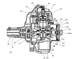
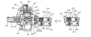
- FIG. 1 shows a configuration of a power unit 30 used here.
- This power unit 30 is used instead of the power unit 330 in FIG.
- FIG. 1 is a cross-sectional view along the crankshaft of the engine 40
- FIG. 2 is a perspective view seen from the front side (left side in FIG. 1).
- the engine 40 used here is a two-cycle air-cooled engine, and is the same as ordinarily known except for the mechanism related to its starting.
- the reciprocating motion of the piston 42 in the cylinder 41 in the vertical direction is converted into the rotational motion of the crankshaft 43 and output.
- the rotational movement of the crankshaft 43 is transmitted to the transmission shaft 21 in the operating rod 20 via the centrifugal clutch 44.
- an ignition plug 45 for igniting the compressed air-fuel mixture introduced into the combustion chamber formed on the upper side of the piston 42 is mounted, and the ignition plug 45 is plugged with a plug cap 46 for energizing the ignition plug 45.
- This current is generated by boosting the current generated by a generator (not shown) with the rotation of the crankshaft 43 by an ignition coil (not shown), and flows to the spark plug 45 at an appropriate timing.
- the cylinder 41 is covered with an upper cover 47 from the upper side, and cooling air generated by a cooling fan (not shown) fixed to the crankshaft 43 flows through the inside covered with the upper cover 47.
- the cylinder 41 is cooled (air cooled). *
- a carburetor 70 is connected to a cylinder 41 via an insulator 71 at an intake port provided on the left side (right side in FIG. 2) of the engine 40. Air is introduced into the vaporizer 70 through an air cleaner 50 mounted on the left side thereof.
- a fuel tank 60 is provided below the engine 40, and an operator can remove the tank cap 61 and supply fuel (mixed fuel of gasoline and two-cycle oil) into the tank. Fuel is supplied to the carburetor 70 through a fuel pipe 62 from a fuel filter 63 provided at the tip of a fuel pipe 62 in the fuel tank 60.
- a box-like muffler 80 is attached to an exhaust port provided on the right side (left side in FIG. 2) of the engine 40, and the exhaust gas passes through the muffler 80 and is discharged into the atmosphere.
- a plurality of expansion chambers are provided in the muffler 80, and since a catalyst is provided in these chambers, exhaust gas is purified and exhaust noise is also reduced.
- a muffler 80 that is hot during operation is also covered with a muffler cover 81.
- a priming pump 72 that is manually operated is attached to the vaporizer 70. By operating (pushing) the priming pump 72 by the operator, pressure toward the carburetor 70 can be generated, and fuel can be guided from the fuel tank 60 to the carburetor 70 via the fuel pipe 62.
- the priming pump 72 has a hemispherical shape made of a transparent resin material, and it can be visually confirmed that fuel is present therein.
- the concentration of the air-fuel mixture generated by the carburetor 70 is determined by the setting of the carburetor 70, and this setting is performed so that the output of the engine 40 can be efficiently exhibited during operation. Optimized.
- a choke lever 73 is provided in the vaporizer 70. When the choke lever 73 is turned on (pulled), the air-fuel mixture concentration can be increased by narrowing the air passage.
- the operator can start the engine 40 with the choke lever 73 pulled at the time of starting, and when the engine 40 starts, the engine 40 can be put into an operating state by returning the choke lever 73.
- the fuel is first guided to the carburetor 70 using the priming pump 72, and the crankshaft 43 is forcibly rotated with the choke lever 73 pulled. It is necessary to make it.
- FIG. 3 is a diagram showing a cross-sectional view in the AA direction of FIG.
- FIG. 3A shows an initial state
- FIG. 3B shows an accumulated state
- FIG. 3C shows a state where the accumulated force is released and the crankshaft 43 is rotated. It is shown. *
- a mainspring case 102 is rotatably provided inside the case 101 with a mainspring spring 103 accommodated therein.
- the mainspring case 102 is connected to a power storage shaft 104 provided at the rear (right side in FIG. 1). Further, the spiral spring 103 is wound as shown in FIG.
- a central shaft 105 is provided at the center of the mainspring case 102, and the central shaft 105 is connected to a one-way clutch 106 provided on the front side (left side in FIG. 1).
- the one-way clutch 106 transmits rotation from the central shaft 105 to the crankshaft 43 during normal rotation (rotation in the direction in which the crankshaft 43 rotates during normal operation), but from the crankshaft 43 to the central shaft 105 side. Does not transmit rotation. For this reason, when the crankshaft 43 is stopped, if the center shaft 105 is rotated forward, the crankshaft 43 can be driven (rotated), and the engine 40 can be started. On the other hand, when the central shaft 105 stops after starting, the central shaft 105 is not affected by the rotation of the crankshaft 43 even if the crankshaft 43 rotates.
- the mainspring 103 is mounted in the mainspring case 102 so as to wind the central shaft 105.
- the inner end of the spring spring 103 is fixed to the central shaft 105, and the outer end thereof is fixed to the inner surface of the spring case 102.
- a claw 107 is provided on the outer surface of the mainspring case 102, and the claw 107 fixes the end of the mainspring spring 103 to prevent the mainspring spring 103 from falling off the mainspring case 102.
- the mainspring case 102 is press-fitted into the power storage shaft 104, and the mainspring case 102 can be driven by driving the power storage shaft 104.
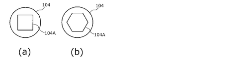
- an engaging portion 104A capable of engaging with an external rotating shaft is provided so that it can be rotated from the outside.
- the shape of the end face of the energy storage shaft 104 viewed from the rear side (right side in FIG. 1) is a rectangular recess at the rear end of the energy storage shaft 104.
- the engaged portion 104A is formed.
- the force accumulation shaft 104 can be rotated forward by engaging the engaging portion 104A with a rotating shaft having a convex portion having the same shape as that of the engaging portion 104A.
- the power storage shaft 104 (the mainspring case 102) can be rotated in the forward direction to store the mainspring spring 103 in the state shown in FIG.
- the shape of the engaging portion 104A is arbitrary as long as such an operation is possible.
- the engaging portion 104A has a hexagonal shape, a spline shaft or diagonally It is sufficient that the two surfaces are non-circular in which a concave portion is formed and power can be transmitted.
- the engaging portion 104A of the accumulator shaft 104 is formed as a convex portion, it may be formed as a concave portion and rotated by the convex portion.
- the mainspring 105 rotates the central shaft 105 and the crankshaft 43.
- the force stored in the mainspring spring 103 is released at once, so that the crankshaft 43 can be rotated with a strong force so that the piston 42 reciprocates a plurality of times. .
- the engine 40 is started.
- the crankshaft 43 rotates spontaneously, the rotation of the crankshaft 43 is suppressed from being transmitted to the central shaft 105 due to the presence of the one-way clutch 106.
- the accumulator shaft 104 is not affected by the rotation of the crankshaft 43. That is, the one-way clutch 106 does not affect the rear side of the center shaft 105 after the engine 40 is started.
- the engine 40 can be easily started by rotating the accumulator shaft 104 (engagement unit 104A) from outside.
- the accumulator type drive unit 100 includes the lightweight one-way clutch 106, the mainspring spring 103, and the like, so that the accumulator type drive unit 100 can be reduced in weight. For this reason, the whole brush cutter can be made lightweight.
- a starting device that rotates the accumulator shaft 104 via the engaging portion 104A a device that can be attached to the accumulator shaft 104 only when the engine 40 is started can be used as a separate body from the brush cutter.
- Any starting device may be used as long as it includes a rotating shaft that can be engaged with the engaging portion 104A and a starting mechanism that drives the rotating shaft.
- manual, electric, or high-pressure air can be used.
- manual operation that does not require connection with facility power or electric power that uses a battery as a power source is particularly preferable.
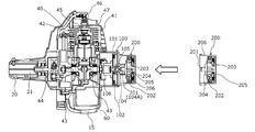
- FIG. 5 is a diagram showing a configuration when the manual starter 200 is used.
- a commonly known recoil starter for example, a device that drives a rotating shaft with a structure described in JP 2012-140904 A can be used.
- the front end (left end in FIG. 5) of the rotating shaft 201 has a quadrangular shape when viewed in the axial direction so as to engage with the engaging portion 104A.
- a reel 203 around which a rope 202 is wound is used, and the reel 203 is rotated forward by pulling out the rope 202 from the reel 203.
- the pulley 204 in front of the reel 203 also rotates in the forward direction, and the rotating shaft 201 fixed to the pulley 204 rotates.
- the rope drawn out by the spring 205 is rewound onto the reel 203.
- the reverse rotation when the rope is rewound is not transmitted to the pulley 204 side by the ratchet mechanism.
- the reel 203, the pulley 204, and the like are covered with a cover 206, and the rope 202 is pulled out from the cover 206.
- the rotating shaft 201 can be rotated in the forward direction by repeatedly performing an operation of pulling the rope 202 while the rotating shaft 201 is engaged with the engaging portion 104A.
- the crankshaft 43 can be driven after the mainspring 103 is sufficiently stored.
- the torque at which the crankshaft 43 is driven at this time can be sufficiently larger than the torque that the operator rotates the reel 203 by the rope 202.
- the engine 40 can be started more easily than when the engine is started using a normal recoil starter.
- the cover 206 and the case 101 can be fixed so that the cover 206 of the starting device 200 can be fixed to the case 101 of the accumulator type drive unit 100 with the rotating shaft 201 engaged with the engaging portion 104A. It is preferable to provide a concave portion on one side and a convex portion engaging with this on the other side.
- the configuration on the left side of FIG. 5 can be obtained only when the engine 40 is started, and after starting, the starting device 200 can be removed and the brush cutter can be used. Since the starter 200 is mounted when the engine 40 is started, the whole becomes heavy. However, the start work is performed in a state where the brush cutter is placed on the ground or the like, so that the weight is not a problem. In addition, since the accumulating drive unit 100 is used, the engine 40 can be started particularly easily, and the engine 40 can be easily started by a single operation in which the accumulating force in the mainspring spring 103 is released. On the other hand, since the starter 200 is not mounted during work, the brush cutter (engine 40) can be made lighter.
- FIG. 6 shows a form in the case of using the starting device 210 as in FIG.
- the major components in the starting mechanism 210 are a DC motor 212 that drives the rotating shaft 211 and a storage battery 213 that is a power source thereof.
- the DC motor 212 is housed in the motor case 214 and the storage battery 213 is housed in the storage battery case 215. .
- the motor case 214 and the storage battery case 215 are adjacent to each other in the direction perpendicular to the rotation shaft 211 in order to shorten the overall length.
- the current from the storage battery 213 flows through the DC motor 212 after being controlled by the control circuit 217 via the terminal 216.
- This on / off can be controlled by a switch (not shown) provided on the surface of the motor case 214 or the storage battery case 215.
- a pinion gear 218 is fixed to the output shaft of the DC motor 212, and the rotation of the pinion gear 218 is transmitted to the spindle 220 through the planetary gear mechanism 219 at a reduction ratio appropriate for starting.
- the rotating shaft 211 is fixed to the spindle 220. Since the current flowing through the DC motor 212 is appropriately controlled by the control circuit 217, it is possible to prevent the DC motor 212 and the like from being burned when overloaded. *
- the starter 210 can also be used in the same manner as the manual starter 200 described above. That is, the engine 40 can be easily started by engaging the rotating shaft 211 with the engaging portion 104A and turning on the switch. At this time, it is preferable that the motor case 214 can be engaged with the case 101. Since the DC motor 212 and the storage battery 213 are provided, the starter 210 is heavier than the manual starter 200. However, since the starter 210 is unnecessary during the operation, the starter 210 is removed, The brush cutter can be made lightweight.
- FIG. 7A shows a configuration in the case of using a starter 230 that is a modification of the electric starter 210.
- the motor case 214 and the storage battery case 215 are arranged in a direction perpendicular to the longitudinal direction (the direction of the rotating shaft 211) in order to shorten the overall length.
- the motor case 231 and the storage battery case 232 are connected in the longitudinal direction.
- the switch 234 is provided on the surface of the motor case 231, it is easy to operate the switch 234 while engaging the rotating shaft 233 with the engaging portion 104A.
- FIGS. 8A and 8B show the configuration in this case as in FIGS. 7A and 7B.
- the mainspring case 102, the mainspring spring 103, the central shaft 105, and the one-way clutch 106 are used in the same manner as the accumulator type drive unit 100, and the one-way clutch 106 and the crankshaft. The same applies to the connection with the terminal 43.
- the accumulator shaft 111 used here is not provided on the extension line of the crankshaft 43 but is provided above the crankshaft 43.
- the accumulator shaft 111 drives the mainspring case 102 via a mainspring case drive gear 112 fixed to the accumulator shaft 111.
- the rear end portion of the accumulator shaft 111 becomes the engaging portion 111A as in the case described above.
- the case 113 is larger in the vertical direction than the case 101 in order to cover the entire configuration. In this case, the direction in which the energy storage shaft 111 (rotary shaft 233) is rotated is the direction opposite to the forward direction of the crankshaft 43.
- the engine 40 in the brush cutter is started in a state where the brush cutter is placed on the ground. Further, as shown in FIG. 1 and the like, the crankshaft 43 is generally provided below the engine 40. For this reason, at the time of start-up, the crankshaft 43 is usually located at a location close to the ground. In such a case, as shown in FIG. 8, the operation of the starting device 230 becomes particularly easy by making the accumulator shaft 111 higher than the crankshaft 43. In particular, it becomes easy to use the elongated starting device 230 in a bent state. It is obvious that the manual starter 200 can be used in this form.
- the energy storage shaft may be configured to have an angle with respect to the crankshaft, and the engaging portion of the energy storage shaft may be positioned higher than the crankshaft. If the operability is not taken into consideration, the starter 230 can be started even when the accumulator shaft is on the extension line of the crankshaft 43. *
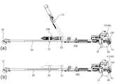
- FIG. 9 is a side view showing the configuration of such a brush cutter 400.
- FIG. 9A shows a form when the starting device 230 is attached
- FIG. 9B shows a form when it is not attached.
- the description of the cutting blade 11 is omitted in FIGS. 9A and 9B, and the description of the handle 13 is further omitted in FIG. 9B.
- the starting device 230 can be fixed along the operating rod 20 using the starting device fixing tool 22 provided near the center of the operating rod 20. At this time, if the elongated starting device 230 is attached to the antinode portion of the natural vibration mode of the operating rod 20 (the portion where the amplitude of vibration is large: the center portion in FIG. 9), the overall weight of the brush cutter 400 is increased. In addition, the starter 230 serves as a weight, so that vibration and deformation of the operation rod 20 can be suppressed. Further, it is possible to prevent the starter 230 from being lost when not in use. *
- the motor case and the storage battery case can be separated, only one of them, for example, only the motor case can be mounted.
- a storage battery case that can also be used as a power source for other work equipment is used, such a configuration is particularly preferable, and the weight of the portion attached to the brush cutter can be reduced. In this way, only a part of the starting device can be attached to the brush cutter.
- the parts to be mounted are small and light, the degree of freedom of the mounting position on the operating rod is increased. Further, other than the operating rod, for example, this is mounted in the gap between the fuel tank and the protective cover. You can also *
- the manual starter 200 and the electric starters 210 and 230 can be used as the starter, but the tip portion of the rotating shaft in these can be engaged with the engaging portion.
- which starting device is used is arbitrary.
- the electric starter 210 or 230 is usually used which is particularly easy to work, and the manual starter 200 is used as an emergency in the case where it is difficult to rotate the motor because the remaining amount of the storage battery is exhausted. Can also be used. *
- the engine working machine is a brush cutter.
- the above configuration is also effective in a working machine in which the engine is similarly used, such as a chain saw or a cultivator.
- the configuration of the engine is arbitrary, and the above configuration is effective even in a 4-cycle engine.
Landscapes
- Engineering & Computer Science (AREA)
- Chemical & Material Sciences (AREA)
- Combustion & Propulsion (AREA)
- Mechanical Engineering (AREA)
- General Engineering & Computer Science (AREA)
- Life Sciences & Earth Sciences (AREA)
- Environmental Sciences (AREA)
- Harvester Elements (AREA)
Abstract
L'invention a pour but d'obtenir une machine de travail à moteur de faible poids qui puisse être démarrée facilement. Pour atteindre ce but, selon l'invention, un arbre rotatif (201) peut être amené à tourner dans un sens vers l'avant par un travailleur en tirant plusieurs fois sur une corde (202) pendant que l'arbre rotatif (201) est en prise avec une partie de mise en prise (104A). Un arbre d'accumulation de force (104) est ainsi entraîné, et une force peut être accumulée dans un ressort en spirale plat (103) dans une unité d'entraînement à accumulation de force (100). Un vilebrequin (43) peut ensuite être entraîné après qu'une force suffisante a été accumulée dans le ressort en spirale plat (3). Du fait qu'une force est accumulée dans le ressort en spirale plat (103) à ce moment, le couple par lequel le vilebrequin (43) est entraîné à ce moment peut être suffisamment augmenté au-dessus du couple avec lequel le travailleur fait tourner un rouleau (203) au moyen de la corde (202).
Applications Claiming Priority (2)
| Application Number | Priority Date | Filing Date | Title |
|---|---|---|---|
| JP2014039166A JP2015161296A (ja) | 2014-02-28 | 2014-02-28 | エンジン作業機 |
| JP2014-039166 | 2014-02-28 |
Publications (1)
| Publication Number | Publication Date |
|---|---|
| WO2015129357A1 true WO2015129357A1 (fr) | 2015-09-03 |
Family
ID=54008684
Family Applications (1)
| Application Number | Title | Priority Date | Filing Date |
|---|---|---|---|
| PCT/JP2015/051862 Ceased WO2015129357A1 (fr) | 2014-02-28 | 2015-01-23 | Machine de travail à moteur |
Country Status (2)
| Country | Link |
|---|---|
| JP (1) | JP2015161296A (fr) |
| WO (1) | WO2015129357A1 (fr) |
Cited By (4)
| Publication number | Priority date | Publication date | Assignee | Title |
|---|---|---|---|---|
| EP3147494A1 (fr) * | 2015-09-22 | 2017-03-29 | Coza International Limited Hongkong | Source de démarreur double source pour un moteur |
| CN106677896A (zh) * | 2017-03-17 | 2017-05-17 | 重庆工业职业技术学院 | 一种燃油内燃机发电机组 |
| CN106888672A (zh) * | 2017-03-06 | 2017-06-27 | 李文新 | 一种用于市政园林工程的便携式割草机 |
| WO2018126327A1 (fr) * | 2017-07-20 | 2018-07-12 | Budden Doyle | Procédé et appareil pour démarrer un petit moteur à combustion externe |
Citations (4)
| Publication number | Priority date | Publication date | Assignee | Title |
|---|---|---|---|---|
| US1936555A (en) * | 1932-02-27 | 1933-11-21 | Eclipse Aviat Corp | Engine starting mechanism |
| JPS63138023U (fr) * | 1987-03-04 | 1988-09-12 | ||
| JPH0184528U (fr) * | 1987-11-27 | 1989-06-05 | ||
| JP2011043081A (ja) * | 2009-08-19 | 2011-03-03 | Makita Corp | 電動工具を用いて作業機のエンジンを始動するためのアタッチメント |
-
2014
- 2014-02-28 JP JP2014039166A patent/JP2015161296A/ja active Pending
-
2015
- 2015-01-23 WO PCT/JP2015/051862 patent/WO2015129357A1/fr not_active Ceased
Patent Citations (4)
| Publication number | Priority date | Publication date | Assignee | Title |
|---|---|---|---|---|
| US1936555A (en) * | 1932-02-27 | 1933-11-21 | Eclipse Aviat Corp | Engine starting mechanism |
| JPS63138023U (fr) * | 1987-03-04 | 1988-09-12 | ||
| JPH0184528U (fr) * | 1987-11-27 | 1989-06-05 | ||
| JP2011043081A (ja) * | 2009-08-19 | 2011-03-03 | Makita Corp | 電動工具を用いて作業機のエンジンを始動するためのアタッチメント |
Cited By (5)
| Publication number | Priority date | Publication date | Assignee | Title |
|---|---|---|---|---|
| EP3147494A1 (fr) * | 2015-09-22 | 2017-03-29 | Coza International Limited Hongkong | Source de démarreur double source pour un moteur |
| CN106888672A (zh) * | 2017-03-06 | 2017-06-27 | 李文新 | 一种用于市政园林工程的便携式割草机 |
| CN106677896A (zh) * | 2017-03-17 | 2017-05-17 | 重庆工业职业技术学院 | 一种燃油内燃机发电机组 |
| WO2018126327A1 (fr) * | 2017-07-20 | 2018-07-12 | Budden Doyle | Procédé et appareil pour démarrer un petit moteur à combustion externe |
| US10087905B2 (en) | 2017-07-20 | 2018-10-02 | Doyle Budden | Method and apparatus for starting a small combustion engine |
Also Published As
| Publication number | Publication date |
|---|---|
| JP2015161296A (ja) | 2015-09-07 |
Similar Documents
| Publication | Publication Date | Title |
|---|---|---|
| US7748360B2 (en) | Handheld electric starter for engines and method of use | |
| CN103443418B (zh) | 混合动力驱动型便携式工作机 | |
| US7530340B1 (en) | Removable linkage of a modified cordless power drill for gasoline engines to power-assist starting of gasoline engines | |
| WO2015129357A1 (fr) | Machine de travail à moteur | |
| MX150344A (es) | Mejoras en maquinas portatiles provistas con motor de combustion interna para accionar herramientas mecanicas tales como biseladoras,barrenadoras,sierras de cadena,cortadoras de cesped,cortadoras de maleza y similares | |
| US20140165946A1 (en) | Power tool | |
| JP4119632B2 (ja) | 背負式動力作業機用リコイルスタータ装置 | |
| JPH0649899Y2 (ja) | 自動始動器付携帯形作業機械用内燃機関 | |
| US20140083375A1 (en) | Power tool | |
| US9587615B2 (en) | Engine starter attachment for battery operated drill/driver gun | |
| JP6260140B2 (ja) | エンジン作業機 | |
| US5007173A (en) | Gasoline engine powered hand-held circular saw | |
| JP2011043081A (ja) | 電動工具を用いて作業機のエンジンを始動するためのアタッチメント | |
| WO2013043092A1 (fr) | Dispositif de démarreur pour démarrer un moteur à combustion interne | |
| JP3813921B2 (ja) | 内燃エンジンの始動方法及び始動装置 | |
| EP3147494A1 (fr) | Source de démarreur double source pour un moteur | |
| JP2006336522A (ja) | 内燃エンジンの始動装置および始動方法 | |
| JP2011074856A (ja) | エンジン作業機 | |
| JP2014066198A (ja) | 動力工具 | |
| JP2014079240A (ja) | 動力工具 | |
| JP2014058901A (ja) | エンジン作業機 | |
| JP2007046585A (ja) | 携帯型作業機 | |
| JP2010203246A (ja) | エンジン作業機 | |
| JP2015124772A (ja) | エンジン作業機 | |
| JP6090058B2 (ja) | エンジン作業機 |
Legal Events
| Date | Code | Title | Description |
|---|---|---|---|
| 121 | Ep: the epo has been informed by wipo that ep was designated in this application |
Ref document number: 15754578 Country of ref document: EP Kind code of ref document: A1 |
|
| NENP | Non-entry into the national phase |
Ref country code: DE |
|
| 122 | Ep: pct application non-entry in european phase |
Ref document number: 15754578 Country of ref document: EP Kind code of ref document: A1 |