WO2015129379A1 - インホイールモータ駆動装置とダンパとの連結構造およびこの連結構造を備えるサスペンション装置 - Google Patents
インホイールモータ駆動装置とダンパとの連結構造およびこの連結構造を備えるサスペンション装置 Download PDFInfo
- Publication number
- WO2015129379A1 WO2015129379A1 PCT/JP2015/052487 JP2015052487W WO2015129379A1 WO 2015129379 A1 WO2015129379 A1 WO 2015129379A1 JP 2015052487 W JP2015052487 W JP 2015052487W WO 2015129379 A1 WO2015129379 A1 WO 2015129379A1
- Authority
- WO
- WIPO (PCT)
- Prior art keywords
- motor drive
- drive device
- wheel
- wheel motor
- damper
- Prior art date
- Legal status (The legal status is an assumption and is not a legal conclusion. Google has not performed a legal analysis and makes no representation as to the accuracy of the status listed.)
- Ceased
Links
Images

Classifications
-
- B—PERFORMING OPERATIONS; TRANSPORTING
- B60—VEHICLES IN GENERAL
- B60K—ARRANGEMENT OR MOUNTING OF PROPULSION UNITS OR OF TRANSMISSIONS IN VEHICLES; ARRANGEMENT OR MOUNTING OF PLURAL DIVERSE PRIME-MOVERS IN VEHICLES; AUXILIARY DRIVES FOR VEHICLES; INSTRUMENTATION OR DASHBOARDS FOR VEHICLES; ARRANGEMENTS IN CONNECTION WITH COOLING, AIR INTAKE, GAS EXHAUST OR FUEL SUPPLY OF PROPULSION UNITS IN VEHICLES
- B60K7/00—Disposition of motor in, or adjacent to, traction wheel
- B60K7/0007—Disposition of motor in, or adjacent to, traction wheel the motor being electric
-
- B—PERFORMING OPERATIONS; TRANSPORTING
- B60—VEHICLES IN GENERAL
- B60G—VEHICLE SUSPENSION ARRANGEMENTS
- B60G3/00—Resilient suspensions for a single wheel
- B60G3/18—Resilient suspensions for a single wheel with two or more pivoted arms, e.g. parallelogram
- B60G3/20—Resilient suspensions for a single wheel with two or more pivoted arms, e.g. parallelogram all arms being rigid
-
- B—PERFORMING OPERATIONS; TRANSPORTING
- B60—VEHICLES IN GENERAL
- B60G—VEHICLE SUSPENSION ARRANGEMENTS
- B60G2200/00—Indexing codes relating to suspension types
- B60G2200/10—Independent suspensions
- B60G2200/14—Independent suspensions with lateral arms
- B60G2200/144—Independent suspensions with lateral arms with two lateral arms forming a parallelogram
-
- B—PERFORMING OPERATIONS; TRANSPORTING
- B60—VEHICLES IN GENERAL
- B60G—VEHICLE SUSPENSION ARRANGEMENTS
- B60G2204/00—Indexing codes related to suspensions per se or to auxiliary parts
- B60G2204/10—Mounting of suspension elements
- B60G2204/12—Mounting of springs or dampers
- B60G2204/129—Damper mount on wheel suspension or knuckle
-
- B—PERFORMING OPERATIONS; TRANSPORTING
- B60—VEHICLES IN GENERAL
- B60G—VEHICLE SUSPENSION ARRANGEMENTS
- B60G2204/00—Indexing codes related to suspensions per se or to auxiliary parts
- B60G2204/10—Mounting of suspension elements
- B60G2204/18—Mounting of vehicle engines
- B60G2204/182—Electric motor on wheel support
-
- B—PERFORMING OPERATIONS; TRANSPORTING
- B60—VEHICLES IN GENERAL
- B60G—VEHICLE SUSPENSION ARRANGEMENTS
- B60G2300/00—Indexing codes relating to the type of vehicle
- B60G2300/50—Electric vehicles; Hybrid vehicles
-
- B—PERFORMING OPERATIONS; TRANSPORTING
- B60—VEHICLES IN GENERAL
- B60K—ARRANGEMENT OR MOUNTING OF PROPULSION UNITS OR OF TRANSMISSIONS IN VEHICLES; ARRANGEMENT OR MOUNTING OF PLURAL DIVERSE PRIME-MOVERS IN VEHICLES; AUXILIARY DRIVES FOR VEHICLES; INSTRUMENTATION OR DASHBOARDS FOR VEHICLES; ARRANGEMENTS IN CONNECTION WITH COOLING, AIR INTAKE, GAS EXHAUST OR FUEL SUPPLY OF PROPULSION UNITS IN VEHICLES
- B60K17/00—Arrangement or mounting of transmissions in vehicles
- B60K17/04—Arrangement or mounting of transmissions in vehicles characterised by arrangement, location or kind of gearing
- B60K17/043—Transmission unit disposed in on near the vehicle wheel, or between the differential gear unit and the wheel
-
- B—PERFORMING OPERATIONS; TRANSPORTING
- B60—VEHICLES IN GENERAL
- B60K—ARRANGEMENT OR MOUNTING OF PROPULSION UNITS OR OF TRANSMISSIONS IN VEHICLES; ARRANGEMENT OR MOUNTING OF PLURAL DIVERSE PRIME-MOVERS IN VEHICLES; AUXILIARY DRIVES FOR VEHICLES; INSTRUMENTATION OR DASHBOARDS FOR VEHICLES; ARRANGEMENTS IN CONNECTION WITH COOLING, AIR INTAKE, GAS EXHAUST OR FUEL SUPPLY OF PROPULSION UNITS IN VEHICLES
- B60K7/00—Disposition of motor in, or adjacent to, traction wheel
- B60K2007/0038—Disposition of motor in, or adjacent to, traction wheel the motor moving together with the wheel axle
-
- B—PERFORMING OPERATIONS; TRANSPORTING
- B60—VEHICLES IN GENERAL
- B60K—ARRANGEMENT OR MOUNTING OF PROPULSION UNITS OR OF TRANSMISSIONS IN VEHICLES; ARRANGEMENT OR MOUNTING OF PLURAL DIVERSE PRIME-MOVERS IN VEHICLES; AUXILIARY DRIVES FOR VEHICLES; INSTRUMENTATION OR DASHBOARDS FOR VEHICLES; ARRANGEMENTS IN CONNECTION WITH COOLING, AIR INTAKE, GAS EXHAUST OR FUEL SUPPLY OF PROPULSION UNITS IN VEHICLES
- B60K7/00—Disposition of motor in, or adjacent to, traction wheel
- B60K2007/0061—Disposition of motor in, or adjacent to, traction wheel the motor axle being parallel to the wheel axle
-
- B—PERFORMING OPERATIONS; TRANSPORTING
- B60—VEHICLES IN GENERAL
- B60K—ARRANGEMENT OR MOUNTING OF PROPULSION UNITS OR OF TRANSMISSIONS IN VEHICLES; ARRANGEMENT OR MOUNTING OF PLURAL DIVERSE PRIME-MOVERS IN VEHICLES; AUXILIARY DRIVES FOR VEHICLES; INSTRUMENTATION OR DASHBOARDS FOR VEHICLES; ARRANGEMENTS IN CONNECTION WITH COOLING, AIR INTAKE, GAS EXHAUST OR FUEL SUPPLY OF PROPULSION UNITS IN VEHICLES
- B60K7/00—Disposition of motor in, or adjacent to, traction wheel
- B60K2007/0092—Disposition of motor in, or adjacent to, traction wheel the motor axle being coaxial to the wheel axle
Definitions
- the present invention relates to a suspension device for an in-wheel motor drive device that drives steered wheels.
- the in-wheel motor drive device is not only less burdensome on the environment because it is electrically driven, but also installed in the wheel of an automobile to drive the wheel, so that it has a larger cabin than an engine automobile. Space can be secured, which is advantageous. Therefore, as a technique for attaching the in-wheel motor drive device to the vehicle body side, a technique as described in Patent Document 1, for example, is conventionally known.
- the in-wheel motor drive device described in Patent Literature 1 has a seat portion for coupling with a trailing arm of a suspension device at a lower portion thereof.
- a suspension device for suspending the steered wheels for example, a high mount type double wishbone suspension device as described in Patent Document 2 is conventionally known.
- the suspension device of Patent Literature 2 includes an upper arm and a lower arm extending in the vehicle width direction, and a hydraulic damper having a lower end connected to the lower arm and an upper end connected to the vehicle body side member.
- Non-Patent Document 1 In order to drive the steered wheels with the in-wheel motor drive device, a technique of suspending the in-wheel motor drive device with a high-mount double wishbone suspension device has been proposed (for example, see Non-Patent Document 1).
- the hydraulic damper of Non-Patent Document 1 extends in the vertical direction across the rotational axis of the wheel and the in-wheel motor drive device when viewed from the front and the rear of the vehicle.
- the axial direction dimension of the road wheel of the steered wheel is made extremely large so that the inner end in the vehicle width direction of the in-wheel motor drive device does not interfere with the hydraulic damper, and the in-wheel motor drive device on the inner side in the vehicle width direction. It is necessary to accommodate the end in the empty area in the road wheel. If it does so, the king pin of a steered wheel will leave
- the in-wheel motor drive device is steered together with the road wheel, if the turning angle is increased, the in-wheel motor drive device and the hydraulic damper may interfere with each other, or the load wheel and the hydraulic damper may interfere with each other.
- the present invention does not prevent the in-wheel motor driving device and the road wheel from being steered, and avoids the interference between the in-wheel motor driving device and the hydraulic damper and the interference between the road wheel and the hydraulic damper. It is an object of the present invention to provide a connection structure between an in-wheel motor drive device and a damper that can be used.
- the connecting structure of the in-wheel motor driving device and the damper according to the present invention includes an in-wheel motor driving device in which at least an outer end portion in the vehicle width direction is installed in an empty area in the road wheel of the steered wheel, and a vehicle width direction.
- a damper bracket extending at least in the vehicle width direction outside end portion is disposed in the road wheel inner space region, and the vehicle bracket width direction outer end portion of the damper bracket disposed in the road wheel inner space region and the in-wheel motor drive device are rotated.
- a first joint that can be connected, and a damper that has a lower end portion coupled to an inner end portion in the vehicle width direction of the damper bracket and an upper end portion that is attached to the vehicle body side member and absorbs bound and rebound of the in-wheel motor drive device.
- the first joint for rotatably connecting the damper bracket and the in-wheel motor drive device is disposed in the road wheel inner air region, the king pin passes through the road wheel inner air region.
- the first joint can be disposed in the vicinity of the kingpin, and the steered operation of the in-wheel motor drive device is not hindered.
- the damper can be arranged on the inner side in the vehicle width direction than the road wheel, interference between the damper and the road wheel can be avoided regardless of the turning angle.
- the first joint is not particularly limited as long as it allows the in-wheel motor drive device such as a ball joint to be steered.
- the damper is not particularly limited in structure, for example, a cylinder that stores hydraulic pressure, a combination of a damping spring and an extendable rod, or the like.
- the damper bracket may be at least extending in the vehicle width direction, and the damper bracket may be integrally coupled to the lower end portion of the damper, or the damper bracket and the lower end portion of the damper that are formed separately are connected by a bolt or a band. It may be fixed. Moreover, when the axial direction one end part of an in-wheel motor drive device is connected and fixed to a steered wheel, the axial direction other end part of an in-wheel motor drive device may protrude from the empty area
- the location where the outer end of the damper bracket in the vehicle width direction and the in-wheel motor drive device are pivotally connected may be located in the space area inside the road wheel, and the detailed arrangement is not particularly limited.
- the 1st joint is provided in the upper part of an in-wheel motor drive.
- a damper can be arrange
- the upper part of the in-wheel motor drive device only needs to be above the axis of the in-wheel motor drive device, and the position in the front-rear direction is not particularly limited.
- the first joint is disposed substantially immediately above or near the axis of the in-wheel motor drive device.
- the first joint is disposed in the road wheel inner space region so as to overlap with the king pin extending through the upper region and the lower region of the road wheel inner space region.
- the first joint since the first joint overlaps with the kingpin, the turning force is not input from the steered wheels to the damper bracket. Therefore, the damper is not affected by the turning regardless of the turning angle, and the in-wheel motor drive device can be easily turned.
- the first joint may not be overlapped with the kingpin, but may be disposed near the kingpin.
- the king pin refers to the turning axis of the steered wheel configured by a virtual straight line, but may be configured by a part such as a pin at a location away from the first joint.
- an in-wheel motor drive device includes a root portion that extends upward from the in-wheel motor drive device and is positioned in a road wheel inner space region and an upper end that is positioned above the road wheel inner space region. And an upper end of the upper and lower arm is rotatably connected to the vehicle body side member to constitute an upper end of the king pin.
- the layout so that the vehicle body side member that supports the in-wheel motor drive device on the upper side thereof, such as a link member that can swing in the vertical direction of the suspension device, away from the steered wheels.
- the degree of freedom in layout arrangement increases, which contributes to the improvement of the riding comfort performance of the suspension device.
- the free end of the upper arm is rotatably connected to the upper portion of the in-wheel motor drive device in the space area inside the road wheel instead of the upper and lower arms. Also good.
- the suspension device for the steered wheels that suspends the in-wheel motor drive device is not particularly limited, and it should be understood that the shape, number, and arrangement of link members that connect the in-wheel motor drive device and the vehicle body are not limited.
- a steered wheel suspension device to which the connection structure of the present invention is applied is not particularly limited.
- the suspension device is a suspension device that suspends an in-wheel motor drive device and extends in the vehicle width direction, and at least the vehicle width direction outside.
- a damper bracket that is disposed in the inner space of the road wheel and is rotatably connected to the in-wheel motor drive device, a lower end portion is coupled to an inner end portion in the vehicle width direction of the damper bracket, and an upper end portion is the vehicle body side
- a damper that is attached to the member and absorbs bounce and rebound of the in-wheel motor drive device, and a base end that extends in the vehicle width direction and is connected to the vehicle body side member at the vehicle width direction inner end.
- the part has a free end that can swing in the vertical direction, and the free end is pivotally connected to the in-wheel motor drive device so that the space in the road wheel A suspension device and a link member contained in kingpin extends through an upper region and a lower region of the.
- the connecting portion between the damper bracket and the in-wheel motor drive device that are rotatably connected is located in the road wheel. Since it is arrange
- the damper can be disposed on the inner side in the vehicle width direction than the road wheel. Therefore, the interference between the damper and the road wheel can be avoided regardless of the turning angle.
- the structure connected so that rotation is possible should just permit the steering of an in-wheel motor drive device, such as a ball joint, for example, and a structure is not specifically limited.
- the damper is not particularly limited in structure, for example, a cylinder that stores hydraulic pressure, a combination of a damping spring and an extendable rod, or the like.
- the damper bracket may be at least extending in the vehicle width direction, and the damper bracket may be integrally coupled to the lower end portion of the damper, or the damper bracket and the lower end portion of the damper that are formed separately are connected by a bolt or a band. It may be fixed.
- the axial direction other end part of an in-wheel motor drive device may protrude from the empty area
- the link member of the suspension device includes an upper arm that connects the upper portion of the in-wheel motor drive device and the vehicle body side member, and a lower portion of the in-wheel motor drive device and the vehicle body side member that are disposed below the upper arm. And a lower arm to be coupled.
- the connection structure of the present invention can be applied to a double wishbone suspension device.
- the lower part of the in-wheel motor drive device may be located below the axis of the in-wheel motor drive device, and the position in the front-rear direction is not particularly limited.
- the free end of the lower arm is connected to the in-wheel motor drive device substantially immediately above or near the axis of the in-wheel motor drive device.
- the present invention provides an in-wheel motor drive device in which the first joint that pivotably connects the in-wheel motor drive device that steers and the lower end portion of the damper that does not steer overlaps the king pin or is located in the vicinity of the king pin. There is no hindrance to the steering. In addition, interference between the in-wheel motor drive device and the damper can be avoided regardless of the turning angle of the in-wheel motor drive device. According to the present invention, when the in-wheel motor drive device is provided on the steered wheels, a connection structure between the in-wheel motor drive device and the damper of the suspension device can be suitably realized.
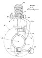
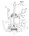
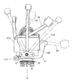
- FIG. 1 is a front view showing a connection structure between an in-wheel motor drive device and a damper according to an embodiment of the present invention, and shows a state observed from the front of the vehicle.
- the connection structure of this embodiment is employed in a suspension device that suspends an in-wheel motor drive device.
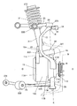
- FIG. 2 is a side view showing the suspension device, and shows a state observed from the inside in the vehicle width direction.
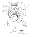
- FIG. 3 is a rear view showing the suspension device, and shows a state observed from the rear of the vehicle.
- FIG. 4 is a plan view showing the suspension device, and shows a state observed from above the vehicle.
- FIG. 5 is a bottom view showing the suspension device, and shows a state observed from below the vehicle.
- FIG. 6 is a bottom view showing the maximum turning angle of the suspension device, and represents the maximum turning angle in the left-right direction.
- the in-wheel motor drive device 11 includes a motor portion 11A, a speed reduction portion 11B, and a hub portion 11C that are sequentially arranged in series coaxially.
- the axis O of the in-wheel motor drive device 11 extends in the vehicle width direction as shown in FIG.
- the motor portion 11A is housed in a casing having a relatively large outer diameter on the inner side in the vehicle width direction
- the speed reducing portion 11B is housed in a casing having a relatively smaller outer diameter on the outer side in the vehicle width direction.
- Such a casing is a non-rotating member that forms an outer shell, whereas the hub portion 11C is a rotating member that protrudes outward in the vehicle width direction from the speed reducing portion 11B, and the load wheel W of the steered wheel indicated by the phantom line is Connect and fix.
- the motor unit 11A incorporates a rotating electric machine in the casing, drives the hub unit 11C, or regenerates power using the rotation of the hub unit 11C.
- the speed reduction part 11B incorporates a speed reduction mechanism such as a cycloid speed reducer in the casing, and reduces the rotation of the motor part 11A and transmits it to the hub part 11C.
- the lower portions of the motor unit 11A and the speed reduction unit 11B have an oil tank 11R that protrudes further to the outer diameter side than the casing of the motor unit 11A and the speed reduction unit 11B and stores oil.
- the hub portion 11C and the speed reduction portion 11B that are relatively located on the outer side in the vehicle width direction are disposed in the inner space of the cylindrical road wheel W.
- the motor portion 11A located relatively inward in the vehicle width direction partially protrudes from the inner space region of the road wheel W to the inner side in the vehicle width direction.
- a third ball joint seat 17 is provided at the lower part of the speed reduction part 11B.
- a first ball joint seat portion 12 that protrudes upward is provided on the upper portion of the speed reduction portion 11B.
- the third ball joint seat portion 17 is positioned substantially immediately below the axis O. Further, the first ball joint seat 12 is positioned substantially immediately above the axis O.
- an upper and lower arm portion 13 extending so as to draw an arc upward from the rear side of the first ball joint seat portion 12 is formed on the upper portion of the speed reduction portion 11B.
- the upper and lower arm portions 13 are integrally coupled to the casing 11G of the in-wheel motor drive device 11 at the root portion, and extend from the root portion to the intermediate portion 13m inward in the vehicle width direction, and then the intermediate portion 13m. Extends from the vehicle to the upper end in the vehicle width direction and avoids interference with the road wheel W (FIG. 3).
- a second ball joint seat 14 is provided at the upper end of the upper and lower arm 13.
- the upper and lower arm portions 13 extend in the vertical direction so as to straddle the road wheel W from the inner space of the road wheel W.
- the upper end portion of the upper and lower arm portions 13 including the second ball joint seat portion 14 is located above the road wheel W.
- upper and lower arm portions 13 once extend rearward from the root portion to the intermediate portion 13m, and then extend forward from the intermediate portion 13m to the upper end portion (FIG. 2).
- the front and rear arm portions 15 further extend forward from the second ball joint seat 14 at the upper end of the upper and lower arm portions 13 (see FIG. 4).
- a tie rod of a steering device (not shown) is connected to the front end 16 of the front / rear arm portion 15.
- the suspension device shown in FIGS. 1 to 6 is a double wishbone suspension device, and includes an upper arm 22 connected to the upper portion of the in-wheel motor drive device 11, a lower arm 23 connected to the lower portion of the in-wheel motor drive device 11, A damper 31 for attenuating the bound amount and the rebound amount of the in-wheel motor drive device 11.
- Each component of the upper arm 22, the lower arm 23, and the damper 31 may be a known component.
- the upper arm 22 is substantially V-shaped as shown in FIG. 4, and can swing on a vehicle body side member (not shown), such as a vehicle body frame, with the vehicle width direction inner ends 221 and 222 at the opposite ends of the V shape as base ends. Connected.
- vehicle body side member such as a vehicle body frame
- the vehicle width direction outer side end portion 223 that becomes the center portion of the V shape forms a free end, and rotates with the second ball joint seat portion 14 at the upper end portion of the upper and lower arm portions 13 via the second ball joint 24.
- the second ball joint 24 is located above the road wheel W (see FIG. 1), and the upper arm 22 has a higher vertical position than the upper arm of the low-mount double wishbone suspension device.
- Mount type double wishbone suspension device is a member on the vehicle body side as viewed from the member described.
- the lower arm 23 includes a front arm extending in the vehicle width direction, and a rear arm that branches from the middle of the front arm and extends obliquely rearward and inward in the vehicle width direction.
- a vehicle body side member such as a vehicle body frame.
- the vehicle width direction outer side end portion 233 of the lower arm 23 forms a free end and is rotatably connected to the third ball joint seat portion 17 at the lower portion of the in-wheel motor drive device 11 via the third ball joint 25.
- the upper arm 22 and the lower arm 23 may be arm members other than the V-shape or the branch shape described above.
- the upper second ball joint 24 and the lower third ball joint 25 enable the in-wheel motor drive device 11 to be steered. That is, the imaginary straight line passing through the second ball joint 24 and the third ball joint 25 constitutes the kingpin K.
- the steered wheels including the in-wheel motor drive device 11 and the road wheel W can be steered in the left-right direction around the kingpin K.
- FIG. 6 shows the positional relationship between the lower arm 23 and the in-wheel motor drive device 11 when turning to the maximum turning angle in the right direction and the left direction. This embodiment is used for the left and right front wheels of a vehicle, for example.
- the first ball joint seat 12 provided in the casing of the in-wheel motor drive device 11 is rotatably connected to the vehicle width direction outer end 321 of the damper bracket 32 via the first ball joint 18. Even if the in-wheel motor drive device 11 is steered by the first ball joint 18, the damper bracket 32 is not steered.
- the damper bracket 32 extends in the vehicle width direction, and at least the outer end portion 321 in the vehicle width direction is disposed in the inner space region of the road wheel W (FIGS. 1 and 3). Further, the inner end 322 in the vehicle width direction of the damper bracket 32 is formed in a cylindrical sleeve shape extending in the vertical direction, and the lower end 311 of the damper 31 is inserted and fixed in the cylindrical sleeve. Such insertion fixing is performed by tightening a bolt 323 attached to the outer periphery of the cylindrical sleeve to reduce the diameter of the cylindrical sleeve.
- the damper 31 extends in the vertical direction, and a lower end portion 311 thereof is coupled to an inner end portion 322 in the vehicle width direction of the damper bracket 32, and an upper end portion 312 is attached to a vehicle body side member (not shown), for example, a top portion of a wheel housing.
- a vehicle body side member not shown
- the damper 31 expands and contracts to attenuate the bounce and rebound of the in-wheel motor drive device 11.
- a terminal box 11E is attached to the upper part of the motor unit 11A, and three power lines 26 and one signal line 27 extend upward from the terminal box 11E.
- the vertical position of the terminal box 11E is substantially the same as the vertical position of the damper bracket 32, the damper bracket 32 is positioned on the outer side in the vehicle width direction than the terminal box 11E (see FIG. 3).
- the first ball joint 18 is disposed in the inner space region of the road wheel W so as to overlap with the kingpin K extending through the upper region and the lower region of the inner space region of the road wheel W. Therefore, even if the in-wheel motor drive device 11 steers, neither the damper bracket 32 nor the damper 31 is steered. Thereby, the suitable steering of the steered wheel containing the in-wheel motor drive device 11 is realizable.
- the in-wheel motor drive device 11 having at least the outer end in the vehicle width direction installed in the inner space of the road wheel W of the steered wheel, and the outer end in the vehicle width direction extending in the vehicle width direction
- the damper bracket 32 is disposed in the inner space region of the road wheel W, and the outer end portion 321 of the damper bracket 32 in the vehicle width direction and the in-wheel motor drive device 11 are rotated.
- the first ball joint 18 that is movably connected, the lower end 311 is coupled to the inner end 322 of the damper bracket 32 in the vehicle width direction, the upper end 312 is attached to the vehicle body side member, and the in-wheel motor drive device 11 is bound.
- a damper 31 for absorbing rebound is
- the first ball joint 18 that rotatably connects the damper bracket 32 and the in-wheel motor drive device 11 is shown in FIGS. 1 and 3.
- the first ball joint 18 can be disposed in the vicinity of the king pin K without being prevented from being steered by the in-wheel motor drive device 11.
- damper 31 can be arranged on the inner side in the vehicle width direction than the road wheel W, interference between the damper 31 and the road wheel W can be avoided regardless of the turning angle.
- the first ball joint 18 is provided on the upper portion of the in-wheel motor drive device 11.
- the lower end 311 of the damper 31 and the upper part of the in-wheel motor drive device 11 are connected via the damper bracket 32 extending in the vehicle width direction, so that the damper 31 is disposed above the in-wheel motor drive device 11. be able to. Therefore, the interference between the damper 31 and the in-wheel motor drive device 11 can be avoided regardless of the turning angle.
- the first ball joint 18 is disposed in the inner space region of the road wheel W so as to overlap with the kingpin K extending through the upper region and the lower region of the inner space region of the road wheel W. Therefore, the turning force is not input to the damper bracket 32 from the steered wheels. Therefore, regardless of the turning angle, the damper 31 is not affected by turning and can easily turn the in-wheel motor drive device 11.
- the in-wheel motor drive device 11 extends upward from the outline of the in-wheel motor drive device 11, the root portion is located in the inner space region of the road wheel W, and the upper end portion is the inside of the road wheel W.
- the upper and lower arms 13 are located above the empty area, and the upper ends of the upper and lower arms 13 are pivotally connected to the upper arms 22 via the second ball joints 24 to form the upper ends of the king pins K.
- a layout arrangement is possible in which the upper arm 22 that supports the in-wheel motor drive device 11 on the upper side of the in-wheel motor drive device 11 is steerable away from the steered wheels, and the degree of freedom in the layout of the upper arm 22 is increased and the suspension is increased. Contributes to improved ride comfort performance of the device.
- the suspension device shown in FIGS. 1 to 6 extends in the vehicle width direction and has at least the outer end portion 321 in the vehicle width direction disposed in the inner space region of the road wheel W in order to suspend the in-wheel motor drive device 11.
- a damper bracket 32 rotatably connected to the in-wheel motor drive device 11 and a lower end portion 311 are coupled to a vehicle width direction inner end portion 322 of the damper bracket 32, and an upper end portion 312 is attached to the vehicle body side member.
- a damper 31 that absorbs the bounce and rebound of the wheel motor drive device 11, a vehicle width direction inner end portion that is connected to the vehicle body side member, and a vehicle width direction outer end portion are in the vertical direction.
- the free end that can swing is formed, and the free end is rotatably connected to the in-wheel motor drive device 11 so as to be an upper region of the inner space region of the road wheel W and And a upper arm 22 and lower arm 23 included in the kingpin K extending through the lower region.
- the first ball joint 18 that rotatably couples the damper bracket 32 and the in-wheel motor drive device 11 can be disposed in the vicinity of the king pin K, and the in-wheel motor drive device 11 and the road wheel W can be arranged. Can be suitably realized.
- the suspension device shown in FIGS. 1 to 6 includes an upper arm 22 that connects the upper part of the in-wheel motor drive device 11 and the vehicle body side member as a vertically swingable link member having a base end and a free end.
- a lower arm 23 that is disposed below the upper arm 22 and connects the lower portion of the in-wheel motor drive device 11 and the vehicle body side member is included. Thereby, the in-wheel motor drive device 11 can be suspended so as to be steerable by the double wishbone suspension device.
- the motor employed in the motor unit 11A is preferably an embedded magnet type synchronous motor (ie, an IPM motor). Further, it may be a radial gap motor or an axial gap motor.
- the in-wheel motor drive device 11 which concerns on this invention, although the example of the cycloid reducer was given, it is not restricted to this, A planetary reducer, a 2 axis parallel reducer, and other reducers can be applied. Also, a so-called direct motor type that does not employ a reduction gear may be used.
- the damper connection structure of the in-wheel motor drive device according to the present invention is advantageously used in electric vehicles and hybrid vehicles.
- In-wheel motor drive unit 12 First ball joint seat, 13 Upper and lower arm, 14 Second ball joint seat, 17 Third ball joint seat, 18 First ball joint, 22 Upper arm, 23 Lower arm, 24 24th 2 ball joint, 25 3rd ball joint, 31 damper, 32 damper bracket, K kingpin, O in-wheel motor drive axis, W road wheel.
Landscapes
- Engineering & Computer Science (AREA)
- Mechanical Engineering (AREA)
- Chemical & Material Sciences (AREA)
- Combustion & Propulsion (AREA)
- Transportation (AREA)
- Vehicle Body Suspensions (AREA)
- Arrangement Or Mounting Of Propulsion Units For Vehicles (AREA)
Abstract
転舵輪のロードホイール(W)内空領域に設置されるインホイールモータ駆動装置(11)と連結するダンパ(31)の連結構造として、ダンパブラケット(32)は車幅方向に延び、少なくとも車幅方向外側端部(321)がロードホイール内空領域に配置される。第1ジョイント(18)はロードホイール内空領域に配置され、ダンパブラケット(32)の車幅方向外側端部(321)とインホイールモータ駆動装置(11)とを回動可能に連結する。ダンパ(31)の下端部(311)はダンパブラケット(32)の車幅方向内側端部(322)と結合する。
Description
本発明は、転舵輪を駆動するインホイールモータ駆動装置のサスペンション装置に関する。
インホイールモータ駆動装置は、電気駆動されることから環境に負荷を与えることが少ないばかりでなく、自動車の車輪内に設置されて当該車輪を駆動することから、エンジン自動車と比較して広い車室スペースを確保することができ、有利である。そこでインホイールモータ駆動装置を車体側に取り付ける技術としては従来、例えば特許文献1に記載のごときものが知られている。特許文献1に記載のインホイールモータ駆動装置は、その下部にサスペンション装置のトレーリングアームと結合するための座部を有する。
一方で、インホイールモータ駆動装置とは無関係に、転舵輪を懸架するサスペンション装置としては従来、例えば特許文献2に記載のごときハイマウント型ダブルウィッシュボーン式サスペンション装置が知られている。特許文献2のサスペンション装置は、車幅方向に延びるアッパアームおよびロアアームと、下端がロアアームに連結され、上端が車体側部材に連結される油圧ダンパとを備える。
また、インホイールモータ駆動装置で転舵輪を駆動するため、インホイールモータ駆動装置をハイマウント型ダブルウィッシュボーン式サスペンション装置で懸架する技術も提案されている(例えば、非特許文献1参照)。
村田智史、「139-20105175 インホイールモータ駆動ユニットの開発」、学術講演会前刷集 No.28-10、社団法人自動車技術会、2010年
非特許文献1のようにインホイールモータ駆動装置を転舵輪のロードホイール内空領域に設けてサスペンション装置で懸架する場合、以下に説明するような問題を生ずる。つまり非特許文献1の油圧ダンパは、車両の前後方向にみた正面視において、車輪およびインホイールモータ駆動装置の回転軸線と交差して上下方向に延びる。このため、インホイールモータ駆動装置の車幅方向内側端部が油圧ダンパと干渉しないように、転舵輪のロードホイールの軸線方向寸法を極端に大きくして、インホイールモータ駆動装置の車幅方向内側端部をロードホイール内空領域に収容する必要がある。そうすると転舵輪のキングピンがロードホイールの軸線方向中央から離れてしまい、転舵輪の転舵に支障をきたす。
あるいは非特許文献1のロードホイールの軸線方向寸法を、特許文献2に記載される転舵輪のロードホイールの軸線方向寸法と同じになるまで短く変更すれば、インホイールモータ駆動装置の車幅方向内側端部が油圧ダンパと干渉してしまう。
またインホイールモータ駆動装置はロードホイールとともに転舵するため、転舵角が大きくなるとインホイールモータ駆動装置と油圧ダンパが互いに干渉したり、ロードホイールと油圧ダンパが互いに干渉したりする虞がある。
かといって、油圧ダンパの位置を変更するとすれば、インホイールモータ駆動装置を含む転舵輪の転舵に支障をきたす虞がある。
本発明は、上述の実情に鑑み、インホイールモータ駆動装置およびロードホイールの転舵を妨げず、しかもインホイールモータ駆動装置と油圧ダンパとの干渉、および、ロードホイールと油圧ダンパとの干渉を回避することできるインホイールモータ駆動装置とダンパとの連結構造を提供することを目的とする。
この目的のため本発明によるインホイールモータ駆動装置とダンパとの連結構造は、少なくとも車幅方向外側端部が転舵輪のロードホイール内空領域に設置されるインホイールモータ駆動装置と、車幅方向に延び少なくとも車幅方向外側端部がロードホイール内空領域に配置されるダンパブラケットと、ロードホイール内空領域に配置されダンパブラケットの車幅方向外側端部とインホイールモータ駆動装置とを回動可能に連結する第1ジョイントと、下端部がダンパブラケットの車幅方向内側端部と結合し上端部が車体側メンバに取り付けられインホイールモータ駆動装置のバウンドおよびリバウンドを吸収するダンパとを備える。
かかる本発明によれば、ダンパブラケットとインホイールモータ駆動装置とを回動可能に連結する第1ジョイントが、ロードホイール内空領域に配置されることから、キングピンがロードホイール内空領域を通過して延びる転舵輪において、第1ジョイントをキングピンの近傍に配置することが可能になりインホイールモータ駆動装置の転舵を妨げることがない。
またダンパをロードホイールよりも車幅方向内側に配置することができるので、転舵角の大小にかかわらずダンパとロードホイールとの干渉を回避することができる。
なお第1ジョイントは例えばボールジョイントなどインホイールモータ駆動装置の転舵を許容するものであればよく、構造を特に限定されない。またダンパは例えば液圧を蓄えるシリンダであったり、減衰ばねおよび伸縮可能なロッドの組み合わせであったり、構造を特に限定されない。またダンパブラケットは少なくとも車幅方向に延びるものであればよく、ダンパブラケットがダンパ下端部と一体結合してもよいし、別体に形成されたダンパブラケットおよびダンパ下端部をボルトやバンド等で連結固定してもよい。またインホイールモータ駆動装置の軸線方向一端部が転舵輪に連結固定される場合、インホイールモータ駆動装置の軸線方向他端部はロードホイール内空領域からはみ出ても良い。
ダンパブラケットの車幅方向外側端部とインホイールモータ駆動装置とを回動可能に連結する箇所はロードホイール内空領域に位置すればよく、詳細な配置は、特に限定されないが、本発明の一実施形態として、第1ジョイントはインホイールモータ駆動装置の上部に設けられる。かかる実施形態によれば、ダンパをインホイールモータ駆動装置よりも上方に配置することができる。したがって転舵角の大小にかかわらずダンパとインホイールモータ駆動装置との干渉を回避することができる。なおインホイールモータ駆動装置の上部とは、インホイールモータ駆動装置の軸線よりも上方にあればよく、その前後方向位置は特に限定されない。好ましい実施形態として第1ジョイントは、インホイールモータ駆動装置の軸線の略直上あるいはその近傍に配置される。
本発明の一実施形態として、第1ジョイントはロードホイール内空領域で、ロードホイール内空領域の上側領域および下側領域を通過して延びるキングピンと重なるように配置される。かかる実施形態によれば、第1ジョイントがキングピンと重なることから、転舵力が転舵輪からダンパブラケットに入力されることがない。したがって転舵角の大小にかかわらずダンパは転舵の影響を受けず、インホイールモータ駆動装置を容易に転舵させることができる。他の実施形態として、第1ジョイントがキングピンとは重ならないもののキングピン近傍に配置されてもよい。なおキングピンとは仮想直線で構成される転舵輪の転舵軸線をいうが、第1ジョイントから離れた箇所でピン等の部品によって構成されてもよい。
本発明の一実施形態として、インホイールモータ駆動装置は、インホイールモータ駆動装置から上方へ向かって延び根元部がロードホイール内空領域に位置し上端部がロードホイール内空領域よりも上方に位置する上下アーム部を有し、上下アーム部の上端部は車体側メンバに回動可能に連結されてキングピンの上端を構成する。かかる実施形態によれば、インホイールモータ駆動装置をその上側で転舵可能に支持する車体側メンバ、例えばサスペンション装置の上下方向に揺動可能なリンク部材、を転舵輪から遠ざけるレイアウト配置が可能になり、レイアウト配置の自由度が大きくなってサスペンション装置の乗り心地性能の改善に資する。他の実施形態として、例えばローマウント型ダブルウィッシュボーン式サスペンション装置において、上下アーム部の代わりにアッパアームの遊端をロードホイール内空領域でインホイールモータ駆動装置の上部と回動可能に連結してもよい。
インホイールモータ駆動装置を懸架する転舵輪のサスペンション装置は特に限定されず、インホイールモータ駆動装置と車体とを連結するリンク部材の形状、本数、および配置は限定されないと理解すべきである。本発明の接続構造が適用される転舵輪のサスペンション装置は特に限定されないが、好ましい実施形態として、インホイールモータ駆動装置を懸架するサスペンション装置であって、車幅方向に延び、少なくとも車幅方向外側端部がロードホイール内空領域に配置されてインホイールモータ駆動装置に回動可能に連結されるダンパブラケットと、下端部がダンパブラケットの車幅方向内側端部と結合し、上端部が車体側メンバに取り付けられ、インホイールモータ駆動装置のバウンドおよびリバウンドを吸収するダンパと、車幅方向に延びて車幅方向内側端部が車体側メンバに連結される基端をなし、車幅方向外側端部が上下方向に揺動可能な遊端をなし、該遊端がインホイールモータ駆動装置に回動可能に連結されてロードホイール内空領域の上側領域および下側領域を通過して延びるキングピンに含まれるリンク部材とを備えるサスペンション装置である。
かかる本発明によれば、上下方向に延びるキングピンがロードホイール内空領域を通過して延びる転舵輪において、回動可能に連結されるダンパブラケットとインホイールモータ駆動装置との連結箇所がロードホイール内空領域に配置されることから、当該連結箇所をキングピンの近傍に配置することが可能になりインホイールモータ駆動装置の転舵を妨げることがない。
しかも車幅方向に延びるダンパブラケットを介してダンパの下端部とインホイールモータ駆動装置とを連結することから、ダンパをロードホイールよりも車幅方向内側に配置することができる。したがって、転舵角の大小にかかわらずダンパとロードホイールとの干渉を回避することができる。
なお回動可能に連結する構成は例えばボールジョイントなどインホイールモータ駆動装置の転舵を許容するものであればよく、構造を特に限定されない。またダンパは例えば液圧を蓄えるシリンダであったり、減衰ばねおよび伸縮可能なロッドの組み合わせであったり、構造を特に限定されない。またダンパブラケットは少なくとも車幅方向に延びるものであればよく、ダンパブラケットがダンパ下端部と一体結合してもよいし、別体に形成されたダンパブラケットおよびダンパ下端部をボルトやバンド等で連結固定してもよい。またインホイールモータ駆動装置の軸線方向一端部が転舵輪に連結固定される場合、インホイールモータ駆動装置の軸線方向他端部はロードホイール内空領域からはみ出ても良い。
好ましい実施形態としてサスペンション装置のリンク部材は、インホイールモータ駆動装置の上部と車体側メンバとを連結するアッパアームと、アッパアームよりも下方に配置されてインホイールモータ駆動装置の下部と車体側メンバとを連結するロアアームとを含む。かかる実施形態によれば、ダブルウィッシュボーン式サスペンション装置に、本発明の接続構造を適用することができる。なおインホイールモータ駆動装置の下部とは、インホイールモータ駆動装置の軸線よりも下方にあればよく、その前後方向位置は特に限定されない。好ましい実施形態としてロアアームの遊端は、インホイールモータ駆動装置の軸線の略直上あるいはその近傍でインホイールモータ駆動装置に連結される。
このように本発明は、転舵するインホイールモータ駆動装置と転舵しないダンパ下端部とを回動可能に連結する第1ジョイントがキングピンに重なり、あるいはキングピン近傍に位置し、インホイールモータ駆動装置の転舵を妨げることがない。そして、インホイールモータ駆動装置の転舵角の大小に関わらず、インホイールモータ駆動装置とダンパとの干渉を回避することができる。本発明は、インホイールモータ駆動装置を転舵輪に設ける場合に、インホイールモータ駆動装置とサスペンション装置のダンパとの連結構造を好適に実現することができる。
以下、本発明の実施の形態を、図面に基づき詳細に説明する。図1は、本発明の一実施形態になるインホイールモータ駆動装置とダンパとの連結構造を示す正面図であり、車両前方から観察した状態を表す。本実施形態の連結構造は、図1に示すように、インホイールモータ駆動装置を懸架するサスペンション装置に採用される。図2はこのサスペンション装置を示す側面図であり、車幅方向内側から観察した状態を表す。図3はこのサスペンション装置を示す背面図であり、車両後方から観察した状態を表す。図4はこのサスペンション装置を示す平面図であり、車両上方から観察した状態を表す。図5はこのサスペンション装置を示す底面図であり、車両下方から観察した状態を表す。図6はこのサスペンション装置の最大転舵角を示す底面図であり、左右方向の最大転舵角をそれぞれ表す。
まずインホイールモータ駆動装置11から説明すると、インホイールモータ駆動装置11は同軸に順次直列配置されたモータ部11A、減速部11B、およびハブ部11Cを備える。転舵輪の転舵角が0°のとき、インホイールモータ駆動装置11の軸線Oは図1に示すように車幅方向に延びる。モータ部11Aは車幅方向内側で相対的に大きな外径のケーシングに収容され、減速部11Bは車幅方向外側で相対的に小さな外径のケーシングに収容される。かかるケーシングは外郭をなす非回転部材であるに対し、ハブ部11Cは減速部11Bから車幅方向外側に突出する回転部材であり、仮想線で示す転舵輪のロードホイールWを複数のボルト19で連結固定する。
モータ部11Aはケーシング内に回転電機を内蔵し、ハブ部11Cを駆動し、あるいはハブ部11Cの回転を利用して電力回生を行う。減速部11Bはケーシング内に例えばサイクロイド減速機などの減速機構を内蔵し、モータ部11Aの回転を減速してハブ部11Cに伝達する。なおモータ部11Aおよび減速部11Bの下部は、モータ部11Aおよび減速部11Bのケーシングよりもさらに外径側に張り出し、オイルを貯留するためのオイルタンク11Rを有する。
相対的に車幅方向外側に位置するハブ部11Cおよび減速部11Bは、円筒形状のロードホイールWの内空領域に配置される。これに対し相対的に車幅方向内側に位置するモータ部11Aは、ロードホイールWの内空領域から車幅方向内側へ一部はみ出ている。減速部11Bの下部には第3ボールジョイント座部17が設けられる。減速部11Bの上部には上方へ突出する第1ボールジョイント座部12が設けられている。なお本実施形態では、第3ボールジョイント座部17は軸線Oの略直下に位置する。また第1ボールジョイント座部12は軸線Oの略直上に位置する。
また減速部11Bの上部には、第1ボールジョイント座部12よりも後側から上方へ弧を描くように延びる上下アーム部13が形成されている。詳細には、上下アーム部13はその根元部でインホイールモータ駆動装置11のケーシング11Gと一体結合し、かかる根元部から中間部分13mまで一旦車幅方向内側へ向かって延び、次に中間部分13mから上端部まで車幅方向外側へ向かって延び、ロードホイールWとの干渉を回避する(図3)。そして上下アーム部13の上端部には第2ボールジョイント座部14が設けられている。このように上下アーム部13はロードホイールWの内空領域からロードホイールWを跨ぐようにして上下方向に延びる。そして第2ボールジョイント座部14を含む上下アーム部13の上端部はロードホイールWよりも上方に位置する。
また上下アーム部13は、その根元部から中間部分13mまで一旦後側へ向かって延び、次に中間部分13mから上端部まで前側へ向かって延びる(図2)。
なお上下アーム部13の上端部の第2ボールジョイント座部14から、前後アーム部15が前方へさらに延びる(図4参照)。前後アーム部15の前端16には図示しないステアリング装置のタイロッドが連結される。
次にインホイールモータ駆動装置11を懸架するサスペンション装置につき説明する。
図1~図6に示すサスペンション装置は、ダブルウィッシュボーン式サスペンション装置であり、インホイールモータ駆動装置11の上部と連結するアッパアーム22と、インホイールモータ駆動装置11の下部と連結するロアアーム23と、インホイールモータ駆動装置11のバウンド量およびリバウンド量を減衰させるダンパ31とを備える。アッパアーム22、ロアアーム23、およびダンパ31の各部品自体は公知のものでよい。
アッパアーム22は図4に示すように略V字状であり、V字の両端になる車幅方向内側端部221,222を基端として図示しない車体側メンバ、例えば車体フレーム、に揺動可能に連結される。これに対しV字の中央部になる車幅方向外側端部223は遊端をなし、第2ボールジョイント24を介して、上下アーム部13の上端部の第2ボールジョイント座部14と回動可能に連結する。第2ボールジョイント24はロードホイールWよりも上方に位置し(図1参照)、アッパアーム22の上下方向位置はローマウント型ダブルウィッシュボーン式サスペンション装置のアッパアームよりも高いことから、このサスペンション装置はハイマウント型ダブルウィッシュボーン式サスペンション装置である。なお車体側メンバとは、説明される部材からみて車体側にある部材をいうと理解されたい。
ロアアーム23は図5に示すように車幅方向に延びる前側アームと、この前側アームの途中から分岐して後方かつ車幅方向内側へ斜めに延びる後側アームからなり、前側の車幅方向内側端部231および後側の車幅方向内側端部232を基端として図示しない車体側メンバ、例えば車体フレーム、に揺動可能に連結される。これに対しロアアーム23の車幅方向外側端部233は遊端をなし、第3ボールジョイント25を介して、インホイールモータ駆動装置11の下部の第3ボールジョイント座部17と回動可能に連結する。
このようにロアアーム23の車幅方向外側端部233と、第3ボールジョイント25と、インホイールモータ駆動装置11の下部に設けられた第3ボールジョイント座部17は、ロードホイールWの内空領域に配置される。なお図には示さなかったが、アッパアーム22およびロアアーム23は上述したV字形状あるいは分岐形状以外のアーム部材であってもよいこと勿論である。
上側の第2ボールジョイント24および下側の第3ボールジョイント25は、インホイールモータ駆動装置11の転舵を可能にする。すなわち第2ボールジョイント24および第3ボールジョイント25を通る仮想直線はキングピンKを構成する。そして、インホイールモータ駆動装置11とロードホイールWを含む転舵輪は、キングピンKを中心として左右方向に転舵可能にされる。図6は、右方向および左方向に最大転舵角まで転舵する場合のロアアーム23およびインホイールモータ駆動装置11の位置関係を示す。本実施形態は、例えば車両の左右の前輪に使用される。
インホイールモータ駆動装置11とダンパ31との連結構造につき説明する。
インホイールモータ駆動装置11のケーシングに設けられた第1ボールジョイント座部12は第1ボールジョイント18を介してダンパブラケット32の車幅方向外側端部321に回動可能に連結される。第1ボールジョイント18によりインホイールモータ駆動装置11が転舵してもダンパブラケット32は転舵しない。ダンパブラケット32は車幅方向に延び、少なくとも車幅方向外側端部321がロードホイールWの内空領域に配置される(図1、図3)。またダンパブラケット32の車幅方向内側端部322は、上下方向に延びる円筒スリーブ形状に形成され、この円筒スリーブ内にダンパ31の下端部311が差し込み固定される。かかる差し込み固定は、円筒スリーブの外周に取り付けられたボルト323を締め付けて円筒スリーブを縮径させることによって行う。
ダンパ31は上下方向に延び、その下端部311がダンパブラケット32の車幅方向内側端部322と結合し、その上端部312が図示しない車体側メンバ、例えばホイールハウジングの頂上部、取り付けられる。アッパアーム22およびロアアーム23が上下に揺動してインホイールモータ駆動装置11が車体に対してバウンドおよびリバウンドすると、ダンパ31が伸縮してインホイールモータ駆動装置11のバウンドおよびリバウンドを減衰させる。
ここで付言すると、モータ部11Aの上部には端子ボックス11Eが附設され、端子ボックス11Eから3本の電力線26および1本の信号線27が上方へ向かって延びる。端子ボックス11Eの上下方向位置はダンパブラケット32の上下方向位置と略同じであるが、ダンパブラケット32は端子ボックス11Eよりも車幅方向外側に位置する(図3参照)。また第1ボールジョイント18は、ロードホイールWの内空領域で、ロードホイールWの内空領域の上側領域および下側領域を通過して延びるキングピンKと重なるように配置される。したがってインホイールモータ駆動装置11が転舵しても、ダンパブラケット32およびダンパ31がともに転舵することはない。これにより、インホイールモータ駆動装置11を含む転舵輪の好適な転舵を実現することができる。
ところで本実施形態によれば、少なくとも車幅方向外側端部が転舵輪のロードホイールWの内空領域に設置されるインホイールモータ駆動装置11と、車幅方向に延びて少なくとも車幅方向外側端部がロードホイールWの内空領域に配置されるダンパブラケット32と、ロードホイールWの内空領域に配置されてダンパブラケット32の車幅方向外側端部321とインホイールモータ駆動装置11とを回動可能に連結する第1ボールジョイント18と、下端部311がダンパブラケット32の車幅方向内側端部322と結合し、上端部312が車体側メンバに取り付けられ、インホイールモータ駆動装置11のバウンドおよびリバウンドを吸収するダンパ31とを備える。
かかるインホイールモータ駆動装置11とダンパ31との連結構造によれば、ダンパブラケット32とインホイールモータ駆動装置11とを回動可能に連結する第1ボールジョイント18が、図1および図3に示すようにロードホイールWの内空領域に配置されることから、第1ボールジョイント18をキングピンKの近傍に配置することが可能になり、インホイールモータ駆動装置11の転舵を妨げることがない。
またダンパ31をロードホイールWよりも車幅方向内側に配置することができるので、転舵角の大小にかかわらずダンパ31とロードホイールWとの干渉を回避することができる。
また本実施形態によれば、第1ボールジョイント18はインホイールモータ駆動装置11の上部に設けられる。これにより車幅方向に延びるダンパブラケット32を介してダンパ31の下端部311とインホイールモータ駆動装置11の上部とを連結することから、ダンパ31をインホイールモータ駆動装置11よりも上方に配置することができる。したがって転舵角の大小にかかわらずダンパ31とインホイールモータ駆動装置11との干渉を回避することができる。
また本実施形態によれば、第1ボールジョイント18はロードホイールWの内空領域で、ロードホイールWの内空領域の上側領域および下側領域を通過して延びるキングピンKと重なるように配置されることから、転舵力が転舵輪からダンパブラケット32に入力されることがない。したがって転舵角の大小にかかわらずダンパ31は転舵の影響を受けず、インホイールモータ駆動装置11を容易に転舵させることができる。
また本実施形態によれば、インホイールモータ駆動装置11はインホイールモータ駆動装置11の外郭から上方へ向かって延び根元部がロードホイールWの内空領域に位置し上端部がロードホイールWの内空領域よりも上方に位置する上下アーム部13を有し、上下アーム部13の上端部は第2ボールジョイント24を介してアッパアーム22に回動可能に連結されてキングピンKの上端を構成する。これによりインホイールモータ駆動装置11をインホイールモータ駆動装置11の上側で転舵可能に支持するアッパアーム22を転舵輪から遠ざけるレイアウト配置が可能になり、アッパアーム22のレイアウトの自由度が大きくなってサスペンション装置の乗り心地性能の改善に資する。
また図1~図6に示すサスペンション装置は、インホイールモータ駆動装置11を懸架するために、車幅方向に延びて少なくとも車幅方向外側端部321がロードホイールWの内空領域に配置されてインホイールモータ駆動装置11に回動可能に連結されるダンパブラケット32と、下端部311がダンパブラケット32の車幅方向内側端部322と結合し、上端部312が車体側メンバに取り付けられ、インホイールモータ駆動装置11のバウンドおよびリバウンドを吸収するダンパ31と、車幅方向に延びて車幅方向内側端部が車体側メンバに連結される基端をなし、車幅方向外側端部が上下方向に揺動可能な遊端をなし、該遊端がインホイールモータ駆動装置11に回動可能に連結されてロードホイールWの内空領域の上側領域および下側領域を通過して延びるキングピンKに含まれるアッパアーム22およびロアアーム23とを備える。これにより、ダンパブラケット32とインホイールモータ駆動装置11とを回動可能に連結する第1ボールジョイント18をキングピンKの近傍に配置することが可能になり、インホイールモータ駆動装置11およびロードホイールWを含む転舵輪の転舵を好適に実現することができる。
また図1~図6に示すサスペンション装置は、基端および遊端を有する上下方向に揺動可能なリンク部材として、インホイールモータ駆動装置11の上部と車体側メンバとを連結するアッパアーム22と、アッパアーム22よりも下方に配置されてインホイールモータ駆動装置11の下部と車体側メンバとを連結するロアアーム23とを含む。これによりダブルウィッシュボーン式サスペンション装置でインホイールモータ駆動装置11を転舵可能に懸架することができる。
また、モータ部11Aに採用されるモータは埋込磁石型同期モータ(ずなわちIPMモータ)がよい。またラジアルギャップモータであってもよいし、アキシアルギャップモータであってもよい。
さらに、この発明に係るインホイールモータ駆動装置11においては、サイクロイド減速機の例を挙げたが、これに限ることなく、遊星減速機、2軸並行減速機、その他の減速機を適用可能であり、また、減速機を採用しない、所謂ダイレクトモータタイプであってもよい。
以上、図面を参照してこの発明の実施の形態を説明したが、この発明は、図示した実施の形態のものに限定されない。図示した実施の形態に対して、この発明と同一の範囲内において、あるいは均等の範囲内において、種々の修正や変形を加えることが可能である。
この発明になるインホイールモータ駆動装置のダンパ連結構造は、電気自動車およびハイブリッド車両において有利に利用される。
11 インホイールモータ駆動装置、 12 第1ボールジョイント座部、 13 上下アーム部、 14 第2ボールジョイント座部、 17 第3ボールジョイント座部、 18 第1ボールジョイント、 22 アッパアーム、 23 ロアアーム、 24 第2ボールジョイント、 25 第3ボールジョイント、 31 ダンパ、 32 ダンパブラケット、 K キングピン、 O インホイールモータ駆動装置の軸線、 W ロードホイール。
Claims (6)
- 少なくとも車幅方向外側端部が転舵輪のロードホイール内空領域に設置されるインホイールモータ駆動装置と、
車幅方向に延び、少なくとも車幅方向外側端部が前記ロードホイール内空領域に配置されるダンパブラケットと、
前記ロードホイール内空領域に配置され、前記ダンパブラケットの車幅方向外側端部と前記インホイールモータ駆動装置とを回動可能に連結する第1ジョイントと、
下端部が前記ダンパブラケットの車幅方向内側端部と結合し、上端部が車体側メンバに取り付けられ、前記インホイールモータ駆動装置のバウンドおよびリバウンドを吸収するダンパとを備える、インホイールモータ駆動装置とダンパとの連結構造。 - 前記第1ジョイントは前記インホイールモータ駆動装置の上部に設けられる、請求項1に記載のインホイールモータ駆動装置とダンパとの連結構造。
- 前記第1ジョイントは、前記ロードホイール内空領域で、ロードホイール内空領域の上側領域および下側領域を通過して延びるキングピンと重なるように配置される、請求項1または2に記載のインホイールモータ駆動装置とダンパとの連結構造。
- 前記インホイールモータ駆動装置は、インホイールモータ駆動装置から上方へ向かって延び根元部がロードホイール内空領域に位置し上端部がロードホイール内空領域よりも上方に位置する上下アーム部を有し、
前記上下アーム部の上端部は、車体側メンバに回動可能に連結されてキングピンの上端を構成する、請求項1または2に記載のインホイールモータ駆動装置とダンパとの連結構造。 - インホイールモータ駆動装置を懸架するサスペンション装置であって、
車幅方向に延び、少なくとも車幅方向外側端部がロードホイール内空領域に配置されてインホイールモータ駆動装置に回動可能に連結されるダンパブラケットと、
下端部が前記ダンパブラケットの車幅方向内側端部と結合し、上端部が車体側メンバに取り付けられ、前記インホイールモータ駆動装置のバウンドおよびリバウンドを吸収するダンパと、
車幅方向に延びて車幅方向内側端部が車体側メンバに連結される基端をなし、車幅方向外側端部が上下方向に揺動可能な遊端をなし、該遊端がインホイールモータ駆動装置に回動可能に連結されてロードホイール内空領域の上側領域および下側領域を通過して延びるキングピンに含まれるリンク部材とを備える、サスペンション装置。 - 前記リンク部材は、インホイールモータ駆動装置の上部と車体側メンバとを連結するアッパアームと、前記アッパアームよりも下方に配置されてインホイールモータ駆動装置の下部と車体側メンバとを連結するロアアームとを含む、請求項5に記載のサスペンション装置。
Priority Applications (3)
| Application Number | Priority Date | Filing Date | Title |
|---|---|---|---|
| CN201580010550.4A CN106061765B (zh) | 2014-02-27 | 2015-01-29 | 轮内电动机驱动装置和减震器的连结结构以及悬架装置 |
| US15/120,800 US10150359B2 (en) | 2014-02-27 | 2015-01-29 | Link structure between in-wheel motor drive device and damper, and suspension device including the link structure |
| EP15755601.0A EP3112194B1 (en) | 2014-02-27 | 2015-01-29 | Link structure between in-wheel motor drive device and damper, and suspension device including the link structure |
Applications Claiming Priority (2)
| Application Number | Priority Date | Filing Date | Title |
|---|---|---|---|
| JP2014-036241 | 2014-02-27 | ||
| JP2014036241A JP6313610B2 (ja) | 2014-02-27 | 2014-02-27 | インホイールモータ駆動装置とダンパとの連結構造およびこの連結構造を備えるサスペンション装置 |
Publications (1)
| Publication Number | Publication Date |
|---|---|
| WO2015129379A1 true WO2015129379A1 (ja) | 2015-09-03 |
Family
ID=54008705
Family Applications (1)
| Application Number | Title | Priority Date | Filing Date |
|---|---|---|---|
| PCT/JP2015/052487 Ceased WO2015129379A1 (ja) | 2014-02-27 | 2015-01-29 | インホイールモータ駆動装置とダンパとの連結構造およびこの連結構造を備えるサスペンション装置 |
Country Status (5)
| Country | Link |
|---|---|
| US (1) | US10150359B2 (ja) |
| EP (1) | EP3112194B1 (ja) |
| JP (1) | JP6313610B2 (ja) |
| CN (1) | CN106061765B (ja) |
| WO (1) | WO2015129379A1 (ja) |
Cited By (3)
| Publication number | Priority date | Publication date | Assignee | Title |
|---|---|---|---|---|
| CN107848403A (zh) * | 2016-04-06 | 2018-03-27 | Ntn株式会社 | 轮内电动机驱动装置 |
| EP3441251A4 (en) * | 2016-04-06 | 2019-12-11 | NTN Corporation | WIRING STRUCTURE FOR WHEEL-INTEGRATED MOTOR POWER LINE AND WHEEL-INTEGRATED MOTOR DRIVE DEVICE |
| US10723288B2 (en) | 2016-04-06 | 2020-07-28 | Ntn Corporation | Wiring structure for in-wheel motor power line, and in-wheel motor drive device |
Families Citing this family (15)
| Publication number | Priority date | Publication date | Assignee | Title |
|---|---|---|---|---|
| JP6313610B2 (ja) * | 2014-02-27 | 2018-04-18 | Ntn株式会社 | インホイールモータ駆動装置とダンパとの連結構造およびこの連結構造を備えるサスペンション装置 |
| JP2017185912A (ja) * | 2016-04-06 | 2017-10-12 | Ntn株式会社 | インホイールモータ動力線の配線構造およびインホイールモータ駆動装置 |
| EP3246190A1 (en) * | 2016-05-19 | 2017-11-22 | Sunride P&D B.V. | An electrically driven vehicle |
| DE102016006536B4 (de) * | 2016-05-27 | 2018-03-15 | Audi Ag | Elektrische Antriebseinheit für ein Rad eines Kraftfahrzeugs sowie Radaufhängung für die Räder einer Achse eines Kraftfahrzeugs |
| JP6823418B2 (ja) * | 2016-09-30 | 2021-02-03 | Ntn株式会社 | インホイールモータ駆動装置 |
| JP6113348B1 (ja) | 2016-10-18 | 2017-04-12 | Ntn株式会社 | インホイールモータ用動力ケーブルおよびその配線構造・選択方法 |
| CN110121441B (zh) * | 2017-01-10 | 2022-06-17 | 日立安斯泰莫株式会社 | 马达驱动装置 |
| US10093356B2 (en) * | 2017-02-21 | 2018-10-09 | Arvinmeritor Technology, Llc | Suspension system |
| JP7084110B2 (ja) * | 2017-03-31 | 2022-06-14 | Ntn株式会社 | インホイールモータ電気ワイヤの配索構造 |
| JP6963213B2 (ja) * | 2017-12-25 | 2021-11-05 | トヨタ自動車株式会社 | ストラット式サスペンション装置 |
| IT201800003802A1 (it) * | 2018-03-21 | 2019-09-21 | Babini Giorgio Srl | Gruppo di sterzatura per ruote di veicoli |
| TWM584751U (zh) * | 2018-09-04 | 2019-10-11 | 沃爾奇動力機電股份有限公司 | 獨立式後懸吊系統 |
| JP7163857B2 (ja) * | 2019-04-16 | 2022-11-01 | トヨタ自動車株式会社 | インホイールモータユニット結合構造 |
| CN110525512B (zh) * | 2019-09-25 | 2020-07-31 | 吉林大学 | 一种基于麦弗逊悬架的线控转向机构及其控制方法 |
| CN116238276B (zh) * | 2023-03-15 | 2024-08-13 | 艾德斯汽车电机无锡有限公司 | 一种装有轮毂电机汽车的摆臂总成布置结构 |
Citations (4)
| Publication number | Priority date | Publication date | Assignee | Title |
|---|---|---|---|---|
| JPH03112724A (ja) * | 1989-09-25 | 1991-05-14 | Aisin Aw Co Ltd | 車両用モータの配線および配管装置 |
| JP2009202606A (ja) * | 2008-02-26 | 2009-09-10 | Nissan Motor Co Ltd | 車両用操舵装置 |
| JP2010214986A (ja) * | 2009-03-13 | 2010-09-30 | Nissan Motor Co Ltd | サスペンション構造、及びトー角変化調整方法 |
| WO2014178250A1 (ja) * | 2013-04-30 | 2014-11-06 | 日産自動車株式会社 | インホイールモータ駆動車輪用サスペンション装置 |
Family Cites Families (44)
| Publication number | Priority date | Publication date | Assignee | Title |
|---|---|---|---|---|
| US5127485A (en) * | 1988-06-29 | 1992-07-07 | Aisin Aw Co., Ltd. | Electric motorized wheel with integral motorized cooling oil pump |
| GB2250142B (en) * | 1990-11-20 | 1994-11-09 | Aisin Aw Co | Drive gear disposition in a wheel motor |
| JP2896225B2 (ja) * | 1990-11-20 | 1999-05-31 | アイシン・エィ・ダブリュ株式会社 | ホイールモータの潤滑装置 |
| DE4108164A1 (de) * | 1991-03-14 | 1992-09-17 | Porsche Ag | Radaufhaengung |
| US5180180A (en) * | 1991-04-24 | 1993-01-19 | Aisin Aw Co., Ltd. | Wheel supporting apparatus |
| US5150763A (en) * | 1991-04-24 | 1992-09-29 | Aisin Aw Co., Ltd. | Wiring and piping arrangement for a vehicle motor |
| US5087229A (en) * | 1991-05-06 | 1992-02-11 | General Motors Corporation | Independently suspended steerable motor wheel apparatus |
| FR2679842A1 (fr) * | 1991-07-29 | 1993-02-05 | Shm Management Services Ag | Module de roulement moteur, notamment pour vehicule automobile. |
| SE516990C2 (sv) * | 1998-12-29 | 2002-04-02 | Volvo Car Corp | Arrangemang för hjulupphängning i fordon |
| JP3440082B2 (ja) * | 2001-02-19 | 2003-08-25 | 科学技術振興事業団 | 電気自動車用インホイールモーター |
| ES2280523T3 (es) * | 2001-04-16 | 2007-09-16 | Kabushiki Kaisha Bridgestone | Metodo de montaje de motor incorporado en la rueda y sistema con el motor incorporado en la rueda. |
| US7597169B2 (en) * | 2001-12-07 | 2009-10-06 | Gm Global Technology Operations, Inc. | Wheel module |
| JP4038116B2 (ja) * | 2002-11-14 | 2008-01-23 | 本田技研工業株式会社 | 電動機付き車両 |
| DE10304567A1 (de) * | 2003-02-05 | 2004-08-19 | Audi Ag | Radaufhängung für Kraftfahrzeuge |
| JP4225134B2 (ja) * | 2003-06-25 | 2009-02-18 | トヨタ自動車株式会社 | 車両用懸架装置 |
| JP2005081872A (ja) * | 2003-09-04 | 2005-03-31 | Toyota Motor Corp | インホイールモータ |
| JP4311139B2 (ja) * | 2003-09-12 | 2009-08-12 | トヨタ自動車株式会社 | 車輪構造 |
| US7703780B2 (en) * | 2003-09-30 | 2010-04-27 | Toyota Jidosha Kabushiki Kaisha | Wheel supporting apparatus improving ride comfort of vehicle |
| JP2005178410A (ja) | 2003-12-16 | 2005-07-07 | Honda Motor Co Ltd | ハイマウント型ダブルウイッシュボーン式サスペンション装置 |
| JP4628136B2 (ja) * | 2004-02-26 | 2011-02-09 | トヨタ自動車株式会社 | 配線装置 |
| JP2005295773A (ja) * | 2004-04-05 | 2005-10-20 | Bridgestone Corp | インホイールモータの取付方法 |
| JP4276579B2 (ja) * | 2004-05-17 | 2009-06-10 | トヨタ自動車株式会社 | インホイールモータに設けられる部品の搭載構造 |
| JP4200938B2 (ja) * | 2004-05-18 | 2008-12-24 | トヨタ自動車株式会社 | 電動輪 |
| JP4442315B2 (ja) * | 2004-05-18 | 2010-03-31 | トヨタ自動車株式会社 | 電動輪 |
| JP2005329817A (ja) * | 2004-05-20 | 2005-12-02 | Honda Motor Co Ltd | 車両用ホイール駆動装置 |
| JP4139353B2 (ja) * | 2004-05-25 | 2008-08-27 | トヨタ自動車株式会社 | 車輪支持装置 |
| JP4360305B2 (ja) * | 2004-08-25 | 2009-11-11 | トヨタ自動車株式会社 | インホイールモータのハウジング構造 |
| JP2006188153A (ja) * | 2005-01-06 | 2006-07-20 | Toyota Motor Corp | インホイールモータ |
| JP4656998B2 (ja) * | 2005-04-22 | 2011-03-23 | トヨタ自動車株式会社 | インホイールモータの冷却構造 |
| WO2007026199A1 (en) * | 2005-08-31 | 2007-03-08 | Toyota Jidosha Kabushiki Kaisha | In-wheel suspension |
| JP2007191126A (ja) * | 2006-01-23 | 2007-08-02 | Bridgestone Corp | インホイールモータシステム |
| JP4965131B2 (ja) * | 2006-01-27 | 2012-07-04 | トヨタ自動車株式会社 | インホイールモータ |
| ITTO20060894A1 (it) * | 2006-12-15 | 2008-06-16 | Oto Melara Spa | Ruota motorizzata per un veicolo militare |
| JP5163206B2 (ja) * | 2008-03-19 | 2013-03-13 | アイシン精機株式会社 | インホイールモータシステム |
| JP5292626B2 (ja) | 2008-11-12 | 2013-09-18 | Ntn株式会社 | インホイールモータ駆動装置およびインホイールモータ駆動装置用ケーシング |
| JP5325653B2 (ja) * | 2009-05-19 | 2013-10-23 | 東海ゴム工業株式会社 | 電動モータ駆動式車両用の駆動ユニット防振保持装置 |
| JP2011218931A (ja) * | 2010-04-08 | 2011-11-04 | Nissan Motor Co Ltd | 操舵輪用モータ駆動ユニット |
| JP2013103665A (ja) | 2011-11-16 | 2013-05-30 | Nissan Motor Co Ltd | インホイールモータ駆動車輪の転舵装置 |
| JP2013144509A (ja) * | 2012-01-16 | 2013-07-25 | Nissan Motor Co Ltd | インホイールモータ駆動車輪のモータ給電線配索構造 |
| CN102717696B (zh) | 2012-06-21 | 2015-04-01 | 上海中科深江电动车辆有限公司 | 独立驱动、转向和悬架系统 |
| CN105163962B (zh) * | 2013-04-30 | 2017-03-15 | 日产自动车株式会社 | 轮内电动机驱动车轮用悬架装置 |
| JP6271196B2 (ja) * | 2013-09-19 | 2018-01-31 | Ntn株式会社 | インホイールモータ駆動装置 |
| JP6313610B2 (ja) * | 2014-02-27 | 2018-04-18 | Ntn株式会社 | インホイールモータ駆動装置とダンパとの連結構造およびこの連結構造を備えるサスペンション装置 |
| US9914348B2 (en) * | 2014-06-30 | 2018-03-13 | Nissan North America, Inc. | Electric drive motor assembly for a wheel |
-
2014
- 2014-02-27 JP JP2014036241A patent/JP6313610B2/ja not_active Expired - Fee Related
-
2015
- 2015-01-29 US US15/120,800 patent/US10150359B2/en not_active Expired - Fee Related
- 2015-01-29 EP EP15755601.0A patent/EP3112194B1/en active Active
- 2015-01-29 WO PCT/JP2015/052487 patent/WO2015129379A1/ja not_active Ceased
- 2015-01-29 CN CN201580010550.4A patent/CN106061765B/zh not_active Expired - Fee Related
Patent Citations (4)
| Publication number | Priority date | Publication date | Assignee | Title |
|---|---|---|---|---|
| JPH03112724A (ja) * | 1989-09-25 | 1991-05-14 | Aisin Aw Co Ltd | 車両用モータの配線および配管装置 |
| JP2009202606A (ja) * | 2008-02-26 | 2009-09-10 | Nissan Motor Co Ltd | 車両用操舵装置 |
| JP2010214986A (ja) * | 2009-03-13 | 2010-09-30 | Nissan Motor Co Ltd | サスペンション構造、及びトー角変化調整方法 |
| WO2014178250A1 (ja) * | 2013-04-30 | 2014-11-06 | 日産自動車株式会社 | インホイールモータ駆動車輪用サスペンション装置 |
Cited By (4)
| Publication number | Priority date | Publication date | Assignee | Title |
|---|---|---|---|---|
| CN107848403A (zh) * | 2016-04-06 | 2018-03-27 | Ntn株式会社 | 轮内电动机驱动装置 |
| EP3441252A4 (en) * | 2016-04-06 | 2019-12-11 | NTN Corporation | RADIN MOTOR DRIVE UNIT |
| EP3441251A4 (en) * | 2016-04-06 | 2019-12-11 | NTN Corporation | WIRING STRUCTURE FOR WHEEL-INTEGRATED MOTOR POWER LINE AND WHEEL-INTEGRATED MOTOR DRIVE DEVICE |
| US10723288B2 (en) | 2016-04-06 | 2020-07-28 | Ntn Corporation | Wiring structure for in-wheel motor power line, and in-wheel motor drive device |
Also Published As
| Publication number | Publication date |
|---|---|
| US20160361989A1 (en) | 2016-12-15 |
| CN106061765A (zh) | 2016-10-26 |
| EP3112194A1 (en) | 2017-01-04 |
| US10150359B2 (en) | 2018-12-11 |
| EP3112194B1 (en) | 2019-11-20 |
| CN106061765B (zh) | 2019-06-28 |
| EP3112194A4 (en) | 2018-04-11 |
| JP2015160498A (ja) | 2015-09-07 |
| JP6313610B2 (ja) | 2018-04-18 |
Similar Documents
| Publication | Publication Date | Title |
|---|---|---|
| JP6313610B2 (ja) | インホイールモータ駆動装置とダンパとの連結構造およびこの連結構造を備えるサスペンション装置 | |
| JP6112194B2 (ja) | インホイールモータ駆動車輪用サスペンション装置 | |
| CN102126409B (zh) | 车辆 | |
| WO2015198679A1 (ja) | インホイールモータ車のばね下給電装置 | |
| JP5634091B2 (ja) | 不整地走行車両 | |
| JP4765484B2 (ja) | サスペンション装置 | |
| JP2008168803A (ja) | 車両用駆動装置の配設構造 | |
| JP6365008B2 (ja) | 車両用懸架装置 | |
| JP2017007455A (ja) | インホイールモータ駆動装置用サスペンション構造 | |
| JP6613056B2 (ja) | インホイールモータ駆動装置用サスペンション構造 | |
| WO2016181795A1 (ja) | インホイールモータ駆動装置用サスペンション構造 | |
| JP6546485B2 (ja) | インホイールモータ駆動装置用サスペンション構造 | |
| JP6363850B2 (ja) | インホイールモータ駆動装置と転舵機構との連結構造 | |
| KR101316219B1 (ko) | 인-링크 모터 독립현가장치 | |
| JP2022114514A (ja) | 車両懸架システム | |
| JP2008168802A (ja) | 車両用駆動装置の配設構造 | |
| JP2012011901A (ja) | 車両用サスペンション装置 | |
| TWI727346B (zh) | 跨坐型車輛 | |
| JP6766452B2 (ja) | 車両の後輪操舵装置 | |
| JP2020111191A (ja) | インホイールモータ駆動装置用サスペンション構造 | |
| JP2005205976A (ja) | 車両の駆動力伝達装置 | |
| CN115593163A (zh) | 悬架及汽车 | |
| JP2008168801A (ja) | 車両用駆動装置の配設構造 | |
| JP2020050136A (ja) | インホイールモータ駆動装置用ストラット式サスペンション装置 | |
| JP2009137477A (ja) | 操舵装置 |
Legal Events
| Date | Code | Title | Description |
|---|---|---|---|
| 121 | Ep: the epo has been informed by wipo that ep was designated in this application |
Ref document number: 15755601 Country of ref document: EP Kind code of ref document: A1 |
|
| WWE | Wipo information: entry into national phase |
Ref document number: 15120800 Country of ref document: US |
|
| REEP | Request for entry into the european phase |
Ref document number: 2015755601 Country of ref document: EP |
|
| WWE | Wipo information: entry into national phase |
Ref document number: 2015755601 Country of ref document: EP |
|
| NENP | Non-entry into the national phase |
Ref country code: DE |