WO2015129643A1 - 過給機及び船舶 - Google Patents
過給機及び船舶 Download PDFInfo
- Publication number
- WO2015129643A1 WO2015129643A1 PCT/JP2015/055103 JP2015055103W WO2015129643A1 WO 2015129643 A1 WO2015129643 A1 WO 2015129643A1 JP 2015055103 W JP2015055103 W JP 2015055103W WO 2015129643 A1 WO2015129643 A1 WO 2015129643A1
- Authority
- WO
- WIPO (PCT)
- Prior art keywords
- time constant
- power
- speed command
- rotation speed
- motor
- Prior art date
- Legal status (The legal status is an assumption and is not a legal conclusion. Google has not performed a legal analysis and makes no representation as to the accuracy of the status listed.)
- Ceased
Links
Images


Classifications
-
- F—MECHANICAL ENGINEERING; LIGHTING; HEATING; WEAPONS; BLASTING
- F02—COMBUSTION ENGINES; HOT-GAS OR COMBUSTION-PRODUCT ENGINE PLANTS
- F02B—INTERNAL-COMBUSTION PISTON ENGINES; COMBUSTION ENGINES IN GENERAL
- F02B37/00—Engines characterised by provision of pumps driven at least for part of the time by exhaust
- F02B37/04—Engines with exhaust drive and other drive of pumps, e.g. with exhaust-driven pump and mechanically-driven second pump
-
- F—MECHANICAL ENGINEERING; LIGHTING; HEATING; WEAPONS; BLASTING
- F02—COMBUSTION ENGINES; HOT-GAS OR COMBUSTION-PRODUCT ENGINE PLANTS
- F02B—INTERNAL-COMBUSTION PISTON ENGINES; COMBUSTION ENGINES IN GENERAL
- F02B37/00—Engines characterised by provision of pumps driven at least for part of the time by exhaust
- F02B37/12—Control of the pumps
- F02B37/14—Control of the alternation between or the operation of exhaust drive and other drive of a pump, e.g. dependent on speed
-
- F—MECHANICAL ENGINEERING; LIGHTING; HEATING; WEAPONS; BLASTING
- F01—MACHINES OR ENGINES IN GENERAL; ENGINE PLANTS IN GENERAL; STEAM ENGINES
- F01N—GAS-FLOW SILENCERS OR EXHAUST APPARATUS FOR MACHINES OR ENGINES IN GENERAL; GAS-FLOW SILENCERS OR EXHAUST APPARATUS FOR INTERNAL-COMBUSTION ENGINES
- F01N5/00—Exhaust or silencing apparatus combined or associated with devices profiting by exhaust energy
- F01N5/04—Exhaust or silencing apparatus combined or associated with devices profiting by exhaust energy the devices using kinetic energy
-
- F—MECHANICAL ENGINEERING; LIGHTING; HEATING; WEAPONS; BLASTING
- F02—COMBUSTION ENGINES; HOT-GAS OR COMBUSTION-PRODUCT ENGINE PLANTS
- F02B—INTERNAL-COMBUSTION PISTON ENGINES; COMBUSTION ENGINES IN GENERAL
- F02B33/00—Engines characterised by provision of pumps for charging or scavenging
-
- F—MECHANICAL ENGINEERING; LIGHTING; HEATING; WEAPONS; BLASTING
- F02—COMBUSTION ENGINES; HOT-GAS OR COMBUSTION-PRODUCT ENGINE PLANTS
- F02B—INTERNAL-COMBUSTION PISTON ENGINES; COMBUSTION ENGINES IN GENERAL
- F02B37/00—Engines characterised by provision of pumps driven at least for part of the time by exhaust
- F02B37/04—Engines with exhaust drive and other drive of pumps, e.g. with exhaust-driven pump and mechanically-driven second pump
- F02B37/10—Engines with exhaust drive and other drive of pumps, e.g. with exhaust-driven pump and mechanically-driven second pump at least one pump being alternatively or simultaneously driven by exhaust and other drive, e.g. by pressurised fluid from a reservoir or an engine-driven pump
-
- F—MECHANICAL ENGINEERING; LIGHTING; HEATING; WEAPONS; BLASTING
- F02—COMBUSTION ENGINES; HOT-GAS OR COMBUSTION-PRODUCT ENGINE PLANTS
- F02B—INTERNAL-COMBUSTION PISTON ENGINES; COMBUSTION ENGINES IN GENERAL
- F02B39/00—Component parts, details, or accessories relating to, driven charging or scavenging pumps, not provided for in groups F02B33/00 - F02B37/00
- F02B39/02—Drives of pumps; Varying pump drive gear ratio
- F02B39/08—Non-mechanical drives, e.g. fluid drives having variable gear ratio
- F02B39/10—Non-mechanical drives, e.g. fluid drives having variable gear ratio electric
-
- F—MECHANICAL ENGINEERING; LIGHTING; HEATING; WEAPONS; BLASTING
- F02—COMBUSTION ENGINES; HOT-GAS OR COMBUSTION-PRODUCT ENGINE PLANTS
- F02D—CONTROLLING COMBUSTION ENGINES
- F02D29/00—Controlling engines, such controlling being peculiar to the devices driven thereby, the devices being other than parts or accessories essential to engine operation, e.g. controlling of engines by signals external thereto
- F02D29/06—Controlling engines, such controlling being peculiar to the devices driven thereby, the devices being other than parts or accessories essential to engine operation, e.g. controlling of engines by signals external thereto peculiar to engines driving electric generators
-
- H—ELECTRICITY
- H02—GENERATION; CONVERSION OR DISTRIBUTION OF ELECTRIC POWER
- H02P—CONTROL OR REGULATION OF ELECTRIC MOTORS, ELECTRIC GENERATORS OR DYNAMO-ELECTRIC CONVERTERS; CONTROLLING TRANSFORMERS, REACTORS OR CHOKE COILS
- H02P27/00—Arrangements or methods for the control of AC motors characterised by the kind of supply voltage
- H02P27/04—Arrangements or methods for the control of AC motors characterised by the kind of supply voltage using variable-frequency supply voltage, e.g. inverter or converter supply voltage
- H02P27/06—Arrangements or methods for the control of AC motors characterised by the kind of supply voltage using variable-frequency supply voltage, e.g. inverter or converter supply voltage using DC to AC converters or inverters
-
- F—MECHANICAL ENGINEERING; LIGHTING; HEATING; WEAPONS; BLASTING
- F02—COMBUSTION ENGINES; HOT-GAS OR COMBUSTION-PRODUCT ENGINE PLANTS
- F02D—CONTROLLING COMBUSTION ENGINES
- F02D41/00—Electrical control of supply of combustible mixture or its constituents
- F02D41/0002—Controlling intake air
- F02D41/0007—Controlling intake air for control of turbo-charged or super-charged engines
-
- Y—GENERAL TAGGING OF NEW TECHNOLOGICAL DEVELOPMENTS; GENERAL TAGGING OF CROSS-SECTIONAL TECHNOLOGIES SPANNING OVER SEVERAL SECTIONS OF THE IPC; TECHNICAL SUBJECTS COVERED BY FORMER USPC CROSS-REFERENCE ART COLLECTIONS [XRACs] AND DIGESTS
- Y02—TECHNOLOGIES OR APPLICATIONS FOR MITIGATION OR ADAPTATION AGAINST CLIMATE CHANGE
- Y02T—CLIMATE CHANGE MITIGATION TECHNOLOGIES RELATED TO TRANSPORTATION
- Y02T10/00—Road transport of goods or passengers
- Y02T10/10—Internal combustion engine [ICE] based vehicles
- Y02T10/12—Improving ICE efficiencies
Definitions
- the present invention relates to, for example, a supercharger and a ship equipped with the supercharger.
- a hybrid supercharger 100 is known that includes a generator motor 103 coupled to the rotational shaft of the 102.
- the hybrid turbocharger 100 not only uses the exhaust gas discharged from the internal combustion engine as a compressor driving force of the turbocharger but also uses it as a power for driving the generator motor 103 to obtain generated power. .
- the generated electric power of alternating current obtained by the generator motor 103 is converted to direct current power by the first power conversion unit 104, and then converted to three-phase alternating current power of a frequency according to the inboard grid 106 by the second power conversion unit 105. , And is supplied to the inboard system 106.
- the first power converter 104 shown in FIG. 5 functions as an inverter
- the second power converter 105 functions as a converter.
- a control unit (not shown) that controls the first power conversion unit 104 generates a control signal such that the actual rotation number of the generator motor 103 matches the rotation number command given from the upper control device (not shown).
- the electric power corresponding to the rotational speed command is supplied to the generator motor 103, and the actual rotational speed changes.
- the control signal to the first power conversion unit 104 is the rotation number command Change quickly in response to changes in Therefore, for example, when the rotation speed command fluctuates, the power supplied to the generator motor 103 will fluctuate following the fluctuation. If the power supplied to the generator motor 103 fluctuates, it affects the inboard system that is the power supply source, and the voltage or frequency of the inboard system may be unstable. In the case where another power generation device such as a diesel generator is provided for system stability, it is necessary to frequently perform power adjustment by the other power generation device.
- the problems as described above are not limited to hybrid turbochargers, and, for example, in an apparatus provided with a compressor driven by a turbine and pumping external air to an internal combustion engine, and an electric motor connected to the rotation shaft of the compressor. It is a problem that occurs similarly.
- This invention is made in view of such a situation, Comprising: It aims at providing the supercharger and ship which can suppress the fluctuation
- a supercharger including a compressor driven by a turbine and pumping external air to an internal combustion engine, and an electric motor connected to a rotation shaft of the compressor, and converting direct current power into alternating current power.
- Power conversion means having a function of converting and outputting to the motor, and control means for controlling the power conversion means, the control means having a time constant longer than the time constant of the rotational speed command given from the host control means
- a smoothing unit that has a constant and smoothes and outputs a rotation speed command from the upper control unit; and a control for matching the rotation speed of the motor to the rotation speed command output from the smoothing unit
- a control signal generating means for generating a signal.
- the control signal generation unit since the rotation speed command given from the higher control means is smoothed by the smoothing means, the rotation speed command which changes more gently than the rotation speed command given from the higher control means It can be generated in the control means. Then, the control signal generation unit generates a control signal that causes the actual rotation number to coincide with the smoothed rotation speed command and is supplied to the power conversion unit. Therefore, fluctuations in the power output from the power conversion unit to the motor Can be suppressed.
- control means has time constant information in which the electric power fluctuation amount of the electric motor and the time constant are associated, and acquires the time constant corresponding to the current electric power fluctuation amount from the time constant information
- the method may further include time constant changing means for changing the time constant of the smoothing means to the obtained time constant.
- the time constant of the smoothing means is changed according to the amount of power fluctuation from time to time, so an appropriate time constant according to the amount of power fluctuation from time to time is used to It becomes possible to perform smoothing.
- the time constant changing unit repeatedly calculates the power fluctuation amount at predetermined intervals, and when the calculated power fluctuation amount exceeds a predetermined threshold, the time constant for the power fluctuation amount
- the time constant information may be changed such that
- the maximum value of the time constant is set to, for example, a value smaller than the time constant of the motor.
- a vessel including: the above-described supercharger; and an internal combustion engine to which exhaust gas is introduced into the supercharger and to which external air compressed from the supercharger is supplied.
- a third aspect of the present invention is a method of controlling the number of rotations of a compressor by a motor, and smoothing a rotation number command input from a host controller with a time constant longer than a time constant of the rotation number command.
- the electric power supplied to the motor is controlled so that the rotational speed of the motor matches the rotational speed command after smoothing.
- ADVANTAGE OF THE INVENTION According to this invention, it is effective in the ability to suppress the fluctuation
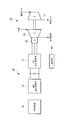
- FIG. 1 is a view showing a schematic configuration of a marine hybrid turbocharger according to an embodiment of the present invention.
- FIG. 2 is a functional block diagram showing functions of the control unit shown in FIG. 1; It is a figure for demonstrating one calculation example of electric power fluctuation amount. It is a figure showing an example of time constant information. It is a figure showing a schematic structure of a conventional marine hybrid supercharger.
- FIG. 1 is a view showing a schematic configuration of a marine hybrid turbocharger (hereinafter simply referred to as "hybrid turbocharger") according to the present embodiment.
- the hybrid turbocharger 10 includes a turbine 21 driven by exhaust gas discharged from a marine diesel engine (internal combustion engine) and a compressor 23 driven by the turbine 21 to pump external air to the marine diesel engine. And a generator motor 30 connected to the rotation shaft of the compressor 23 as a main configuration.
- the hybrid turbocharger 10 not only uses the exhaust gas discharged from the marine diesel engine as the compressor driving force of the turbocharger, but also uses it as a power to drive the generator motor 30 to obtain generated power. .
- the hybrid turbocharger 10 includes a power converter 20 provided between the generator motor 30 and the inboard system 16.
- the power converter 20 includes a first power converter (power converter) 12 and a second power converter 14 as main components.
- the first power conversion unit 12 converts the generated power of the generator motor 30 into DC power and outputs it during regeneration operation of the generator motor 30, and converts the DC power into AC power during power operation and generates power It outputs to the motor 30.
- the second power conversion unit 14 converts the DC power from the first power conversion unit 12 into three-phase AC power suitable for the grid, and outputs it to the inboard grid 16 to perform powering operation. At times, the three-phase AC power from the inboard power system 16 is converted into DC power and is output to the first power converter 12.
- the configurations of the first power conversion unit 12 and the second power conversion unit 14 are not particularly limited. For example, a configuration in which six switching elements are bridge-connected may be mentioned as an example.
- the first power converter 12 is controlled by the controller 40. Although a control unit for controlling the second power conversion unit 14 is also provided, the description here is omitted.
- control unit 40 sets, for example, the actual rotation speed N of the generator motor 30 to the rotation speed command N * given from the upper control device 50 (see FIG. 2) that controls the marine diesel engine. It has a function of controlling the first power converter 12 so as to coincide with each other.
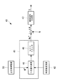
- FIG. 2 is a functional block diagram showing the functions of the control unit 40.
- the control unit 40 mainly shows a smoothing unit 41, a time constant changing unit 42, and a control signal generation unit 43.
- the smoothing unit 41 includes, for example, a first-order lag element 46 and a rate limiter 48.
- the first-order lag element 46 may be realized as hardware such as an RC filter consisting of a resistor and a capacitor component, or may be realized as software.
- a first-order lag element may be further provided downstream of the rate limiter 48.
- the configuration of the smoothing unit 41 is not limited to the configuration shown in FIG. 2, and may have at least one of the primary delay element 46 and the rate limiter 48.
- First-order lag element 46 the rotation speed command N * time constant in the upper level control unit 50 (e.g., a few 100msec for several sec) when longer than constant tau (e.g., 10 times the rotational speed command N * time constant As described above, for example, it has several seconds to several tens of seconds), and smoothes and outputs the rotation speed command N * from the host controller 50.
- the rate limiter 48 limits the rate of change of the rotational speed command output from the primary delay element 46 not to exceed a predetermined value.
- the time constant changing unit 42 calculates the fluctuation amount of power supplied from the first power conversion unit 12 to the generator motor 30 (hereinafter referred to as “power fluctuation amount ⁇ P”), and the first-order lag element according to the power fluctuation amount ⁇ P.
- the power P of the generator motor 30 may be calculated based on, for example, the three-phase AC voltage and the three-phase AC current supplied to the generator motor 30, or the first power converter 12 and the second power converter It may be calculated using the voltage and current between DC buses to and from the unit 14. It is preferable to use the voltage and current between DC buses from the viewpoint of detection accuracy. This is because the three-phase voltage contains a large amount of harmonic components, but the DC voltage has a relatively high accuracy and is easy to calculate because there are few harmonic components due to the effect of the smoothing capacitor.
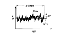
- the power fluctuation amount ⁇ P may be obtained, for example, as a difference between the power average value Pave and the maximum power value Pmax in a predetermined period (see FIG. 3), or a difference between the power average value Pave and the minimum power value Pmin in a predetermined period. It may be determined from the power average value Pave and the standard deviation. The difference between the power average value Pave and the maximum power value Pmax and the difference between the power average value Pave and the minimum power value Pmin in a predetermined period may be calculated, and the larger value may be adopted as the power fluctuation amount ⁇ P. As described above, an appropriate method can be appropriately adopted as a method of calculating the power fluctuation amount ⁇ P. The calculation of the power fluctuation amount ⁇ P is performed periodically at predetermined time intervals.
- the time constant changing unit 42 has time constant information in which the power fluctuation amount ⁇ P and the time constant ⁇ are associated with each other.
- the time constant information may be represented by a function using the power fluctuation amount ⁇ P as a parameter, or may be prepared as a table.
- the time constant changing unit 42 acquires the time constant ⁇ corresponding to the power fluctuation amount ⁇ P from the time constant information, and changes the time constant of the first-order delay element 46 to the acquired time constant ⁇ .
- the time constant changing unit 42 changes the time constant information so that the time constant ⁇ with respect to the power fluctuation amount ⁇ P becomes large. For example, taking time constant information shown in FIG.
- the slope of the time constant characteristic is increased by a predetermined amount.
- the time constant ⁇ is expressed by a function having the power fluctuation amount ⁇ P as a parameter as in the following equation (1)
- the value of the coefficient ⁇ is multiplied by a predetermined amount (for example, 1.1 times).
- the time constant information is changed so as to increase the value of the time constant ⁇ with respect to the same amount of power fluctuation ⁇ P.
- the time constant ⁇ and the power fluctuation amount ⁇ P may not necessarily be in a proportional relationship.
- the maximum value of the time constant ⁇ is set to, for example, a value smaller than the time constant of the generator motor 30.
- the control signal generation unit 43 receives as input the difference between the rotation speed command Ns * output from the smoothing unit 41 and the actual rotation speed N of the generator motor 30, and performs PI control or the like on this difference.
- the control signal of the first power conversion unit 12 for making the actual rotation speed N coincide with the rotation speed command Ns * is generated.
- the control signal generation unit 43 generates a PWM signal for controlling on / off of each switching element included in the first power conversion unit 12.
- a control method for generating a PWM signal to make the actual rotation speed N coincide with the rotation speed command Ns * many known techniques exist, and these known techniques may be adopted appropriately.
- the host controller 50 sets the rotation speed command N * at a predetermined time constant. For example, in the upper control device 50, using the information in which the required load of the internal combustion engine and the rotational speed command are associated with each other, the rotational speed command N * corresponding to the required load of the internal combustion engine is set.
- the control unit 40 when the rotation speed command N * set by the host controller 50 is input, the rotation speed command N * is smoothed by the first-order delay element 46, and the rate limiter 48 changes the change rate to a predetermined value or less.
- a time constant ⁇ set by the time constant changing unit 42 according to the power fluctuation amount ⁇ P at each time is adopted as the time constant of the first-order delay element 46.
- the difference ⁇ N between the smoothed rotation speed command Ns * and the actual rotation speed N is calculated in the difference calculation unit, and the PI control or the like is performed on the difference ⁇ N in the control signal generation unit 43, A control signal S of the first power conversion unit 12 for making the rotational speed N coincide with the rotational speed command Ns * is generated. Then, the control signal S is applied to the first power conversion unit 12, whereby the power corresponding to the rotation speed command Ns * is applied to the generator motor 30, and the rotation speed of the generator motor 30 is controlled.
- the first order lag element 46 also functions as a low pass filter. Therefore, for example, when the rotation speed command N * input from the higher-level controller 50 is a discontinuous point or contains noise, the rotation speed command N * is converted to a continuous value, or It is possible to remove noise.
- the hybrid turbocharger since the time constant of the first-order delay element 46 is changed according to the power fluctuation amount ⁇ P, an appropriate time constant according to the power fluctuation amount ⁇ P at each time The rotation speed command N * can be smoothed using Furthermore, since the time constant information is changed when the power fluctuation amount ⁇ P is equal to or more than the predetermined threshold value, the power fluctuation amount ⁇ P can be made equal to or less than the threshold value by strengthening the effectiveness of the smoothing. For example, even when the characteristics of the first power conversion unit 12 or the generator motor 30 change due to age-related deterioration or the like, having the function of changing time constant information can cope with the change in characteristics due to age-related deterioration or the like.
- the present invention is not limited to the above-described embodiment, and various modifications can be made without departing from the scope of the invention.
- the generator motor 30 capable of both the regeneration (power generation) operation and the power running operation is provided as an electric motor.
- the generator motor 30 instead of the generator motor 30, a motor having only a power running operation without a regeneration function.
- an inverter that converts DC power into AC power and outputs it may be adopted as the power conversion means.
Landscapes
- Engineering & Computer Science (AREA)
- Chemical & Material Sciences (AREA)
- Combustion & Propulsion (AREA)
- Mechanical Engineering (AREA)
- General Engineering & Computer Science (AREA)
- Power Engineering (AREA)
- Supercharger (AREA)
- Control Of Ac Motors In General (AREA)
- Control Of Eletrric Generators (AREA)
Abstract
Description
上記の如き問題は、ハイブリッド過給機に限って生じるものではなく、例えば、タービンにより駆動されて内燃機関に外気を圧送するコンプレッサと、コンプレッサの回転軸に連結される電動機とを備える装置においても同様に発生する問題である。
図1は、本実施形態に係る舶用ハイブリッド過給機(以下単に「ハイブリッド過給機」という。)の概略構成を示した図である。図1に示すように、ハイブリッド過給機10は、舶用ディーゼルエンジン(内燃機関)から排出された排ガスによって駆動されるタービン21と、タービン21により駆動されて舶用ディーゼルエンジンに外気を圧送するコンプレッサ23と、コンプレッサ23の回転軸に連結される発電電動機30とを主な構成として備えている。ハイブリッド過給機10は、舶用ディーゼルエンジンから排出される排ガスを過給機のコンプレッサ駆動力として利用するだけでなく、発電電動機30を駆動する動力としても利用して、発電電力を得るものである。
平滑化部41の構成は、図2に示した構成に限定されず、一次遅れ要素46及びレートリミッタ48のいずれか一方を少なくとも有していればよい。
(1)式において、α>0,b≧0である。
ここで、時定数τの最大値は、例えば、発電電動機30の時定数よりも小さい値に設定される。時定数τの最大値を発電電動機30の時定数よりも小さな値にすることで、回転数制御の応答性を著しく低下させることなく、電力変動を抑制することが可能となる。
更に、電力変動量ΔPが所定の閾値以上である場合には、時定数情報を変更するので、平滑化の効き目を強くすることにより、電力変動量ΔPを閾値以下とすることが可能となる。例えば、経年劣化などにより第1電力変換部12や発電電動機30の特性が変化した場合でも、時定数情報を変更する機能を有することにより、経年劣化等による特性の変化に対応することができる。
例えば、上記の実施形態においては、本発明の過給機を舶用ハイブリッド過給機として船舶に適用した場合を例示して説明したが、本発明の過給機は船舶だけではなく、他の装置にも適用可能である。上記実施形態においては、回生(発電)動作及び力行動作の両方を可能とする発電電動機30を電動機として備える場合を例示したが、発電電動機30に代えて回生機能を有しない力行動作のみの電動機を採用してもよく、この場合には、直流電力を交流電力に変換して出力するインバータを電力変換手段として採用すればよい。
12 第1電力変換部
14 第2電力変換部
16 船内系統
20 電力変換装置
21 タービン
23 コンプレッサ
30 発電電動機
40 制御部
41 平滑化部
42 時定数変更部
43 制御信号生成部
50 上位制御装置
Claims (5)
- タービンにより駆動されて内燃機関に外気を圧送するコンプレッサと、前記コンプレッサの回転軸に連結される電動機とを備えた過給機であって、
直流電力を交流電力に変換して前記電動機に出力する機能を備える電力変換手段と、
前記電力変換手段を制御する制御手段と
を備え、
前記制御手段は、
上位制御手段から与えられる回転数指令の時定数よりも長い時定数を有し、前記上位制御手段からの回転数指令を平滑化して出力する平滑化手段と、
前記平滑化手段から出力された前記回転数指令に、前記電動機の回転数を一致させるための制御信号を生成する制御信号生成手段と
を備える過給機。 - 前記制御手段は、前記電動機の電力変動量と時定数とが関連付けられた時定数情報を有し、現在の電力変動量に対応する時定数を前記時定数情報から取得し、取得した時定数に前記平滑化手段の時定数を変更する時定数変更手段を備える請求項1に記載の過給機。
- 前記時定数変更手段は、前記電力変動量を所定の間隔をおいて繰り返し算出し、算出した前記電力変動量が所定の閾値を超える場合に、前記電力変動量に対する時定数が大きくなるように、前記時定数情報を変更する請求項2に記載の過給機。
- 請求項1から請求項3のいずれかに記載の過給機と、
前記過給機に排ガスを導入するとともに、前記過給機から圧縮された外気が供給される内燃機関と
を備える船舶。 - コンプレッサの回転数を電動機によって制御する方法であって、
上位制御装置から入力される回転数指令を、該回転数指令の時定数よりも長い時定数で平滑化し、平滑化後の回転数指令に前記電動機の回転数を一致させるように、前記電動機へ供給する電力を制御する方法。
Priority Applications (4)
| Application Number | Priority Date | Filing Date | Title |
|---|---|---|---|
| KR1020167016988A KR101842816B1 (ko) | 2014-02-25 | 2015-02-23 | 과급기 및 선박 |
| EP15755012.0A EP3139016B1 (en) | 2014-02-25 | 2015-02-23 | Turbocharger and ship |
| US15/106,238 US10066539B2 (en) | 2014-02-25 | 2015-02-23 | Turbocharger and ship |
| CN201580003455.1A CN105940202B (zh) | 2014-02-25 | 2015-02-23 | 增压器及船舶 |
Applications Claiming Priority (2)
| Application Number | Priority Date | Filing Date | Title |
|---|---|---|---|
| JP2014034152A JP6282487B2 (ja) | 2014-02-25 | 2014-02-25 | 過給機及び船舶 |
| JP2014-034152 | 2014-02-25 |
Publications (1)
| Publication Number | Publication Date |
|---|---|
| WO2015129643A1 true WO2015129643A1 (ja) | 2015-09-03 |
Family
ID=54008961
Family Applications (1)
| Application Number | Title | Priority Date | Filing Date |
|---|---|---|---|
| PCT/JP2015/055103 Ceased WO2015129643A1 (ja) | 2014-02-25 | 2015-02-23 | 過給機及び船舶 |
Country Status (6)
| Country | Link |
|---|---|
| US (1) | US10066539B2 (ja) |
| EP (1) | EP3139016B1 (ja) |
| JP (1) | JP6282487B2 (ja) |
| KR (1) | KR101842816B1 (ja) |
| CN (1) | CN105940202B (ja) |
| WO (1) | WO2015129643A1 (ja) |
Families Citing this family (5)
| Publication number | Priority date | Publication date | Assignee | Title |
|---|---|---|---|---|
| JP6272077B2 (ja) | 2014-02-25 | 2018-01-31 | 三菱重工業株式会社 | 過給機及び船舶 |
| KR20200140504A (ko) * | 2019-06-07 | 2020-12-16 | 가부시키가이샤 미쯔이 이앤에스 머시너리 | 내연기관의 과급기 잉여동력 회수장치 및 선박 |
| CN110296005B (zh) * | 2019-06-28 | 2022-04-15 | 潍柴重机股份有限公司 | 一种天然气发动机双输出模式控制系统及控制方法 |
| US12454906B2 (en) | 2021-05-14 | 2025-10-28 | Garrett Transportation I Inc. | Electric boost device control for turbocharger |
| DE102021206426B3 (de) * | 2021-06-22 | 2022-11-17 | Rolls-Royce Solutions GmbH | Regeleinrichtung zur Regelung einer eine Brennkraftmaschine und einen mit der Brennkraftmaschine antriebswirkverbundenen Generator umfassenden Leistungsanordnung, Regelanordnung mit einer solchen Regeleinrichtung, Leistungsanordnung und Verfahren zur Regelung einer Leistungsanordnung |
Citations (4)
| Publication number | Priority date | Publication date | Assignee | Title |
|---|---|---|---|---|
| JP2003227342A (ja) * | 2002-01-31 | 2003-08-15 | Robert Bosch Gmbh | チャージャの操作または制御方法および装置 |
| JP2011149327A (ja) * | 2010-01-21 | 2011-08-04 | Mitsubishi Heavy Ind Ltd | エンジン排気エネルギー回収装置、これを備える船舶およびこれを備える発電プラント |
| WO2012005046A1 (ja) * | 2010-07-08 | 2012-01-12 | 株式会社Ihi | 排熱回収装置 |
| WO2012137921A1 (ja) * | 2011-04-08 | 2012-10-11 | 株式会社Ihi | 電動アシスト過給機とその制御方法 |
Family Cites Families (16)
| Publication number | Priority date | Publication date | Assignee | Title |
|---|---|---|---|---|
| US3771821A (en) * | 1972-09-25 | 1973-11-13 | Gen Electric | Electronic power control and load rate circuit |
| US4328427A (en) * | 1980-07-07 | 1982-05-04 | General Electric Company | Smooth series parallel transition for dual winding traction alternator |
| CH669977A5 (ja) | 1986-02-27 | 1989-04-28 | Bbc Brown Boveri & Cie | |
| JPH09224393A (ja) * | 1996-02-15 | 1997-08-26 | Daikin Ind Ltd | 空気調和機のファン用誘導電動機制御装置及びファン 用誘導電動機制御方法 |
| US6705084B2 (en) * | 2001-07-03 | 2004-03-16 | Honeywell International Inc. | Control system for electric assisted turbocharger |
| JP3922105B2 (ja) * | 2002-02-06 | 2007-05-30 | 株式会社デンソー | エンジン複合回転電機 |
| JP4548142B2 (ja) * | 2005-02-16 | 2010-09-22 | 株式会社デンソー | 過給アシスト制御システム |
| JP4577168B2 (ja) | 2005-09-13 | 2010-11-10 | 三菱電機株式会社 | 原動機出力の制御装置 |
| JP2008196323A (ja) | 2007-02-08 | 2008-08-28 | Ihi Corp | 電動アシスト式過給機用回転電動機の駆動ユニット用制御装置 |
| US8087401B2 (en) * | 2007-07-18 | 2012-01-03 | Mitsubishi Electric Corporation | Automotive supercharging apparatus |
| JP4916554B2 (ja) | 2010-01-15 | 2012-04-11 | 三菱電機株式会社 | 電動過給機の電源制御装置 |
| US9020731B2 (en) * | 2011-04-05 | 2015-04-28 | Toyota Jidosha Kabushiki Kaisha | Control apparatus for electric motor, electrically-powered vehicle including the control apparatus, and method for controlling electric motor |
| JP5492826B2 (ja) | 2011-06-16 | 2014-05-14 | 日立アプライアンス株式会社 | 交流モータの制御装置、および、これを用いた冷凍空調装置 |
| DE112012006770B4 (de) * | 2012-08-03 | 2019-05-09 | Hitachi, Ltd. | Zweiwellengasturbinen-Stromerzeugungssystem und Steuervorrichtung und Steuerverfahren für ein Gasturbinensystem |
| EP3674123A3 (en) * | 2013-03-12 | 2020-12-09 | Eaton Corporation | Adaptive state of charge regulation and control of variable speed hybrid electric supercharger assembly for efficient vehicle operation |
| US9168914B2 (en) * | 2014-01-14 | 2015-10-27 | Ford Global Technologies, Llc | Vehicle engine and electric machine control |
-
2014
- 2014-02-25 JP JP2014034152A patent/JP6282487B2/ja active Active
-
2015
- 2015-02-23 CN CN201580003455.1A patent/CN105940202B/zh active Active
- 2015-02-23 EP EP15755012.0A patent/EP3139016B1/en active Active
- 2015-02-23 US US15/106,238 patent/US10066539B2/en active Active
- 2015-02-23 WO PCT/JP2015/055103 patent/WO2015129643A1/ja not_active Ceased
- 2015-02-23 KR KR1020167016988A patent/KR101842816B1/ko active Active
Patent Citations (4)
| Publication number | Priority date | Publication date | Assignee | Title |
|---|---|---|---|---|
| JP2003227342A (ja) * | 2002-01-31 | 2003-08-15 | Robert Bosch Gmbh | チャージャの操作または制御方法および装置 |
| JP2011149327A (ja) * | 2010-01-21 | 2011-08-04 | Mitsubishi Heavy Ind Ltd | エンジン排気エネルギー回収装置、これを備える船舶およびこれを備える発電プラント |
| WO2012005046A1 (ja) * | 2010-07-08 | 2012-01-12 | 株式会社Ihi | 排熱回収装置 |
| WO2012137921A1 (ja) * | 2011-04-08 | 2012-10-11 | 株式会社Ihi | 電動アシスト過給機とその制御方法 |
Also Published As
| Publication number | Publication date |
|---|---|
| CN105940202B (zh) | 2018-09-11 |
| EP3139016A1 (en) | 2017-03-08 |
| US20160356206A1 (en) | 2016-12-08 |
| JP2015158188A (ja) | 2015-09-03 |
| KR20160090375A (ko) | 2016-07-29 |
| JP6282487B2 (ja) | 2018-02-21 |
| KR101842816B1 (ko) | 2018-03-27 |
| EP3139016B1 (en) | 2019-03-27 |
| US10066539B2 (en) | 2018-09-04 |
| CN105940202A (zh) | 2016-09-14 |
| EP3139016A4 (en) | 2017-07-12 |
Similar Documents
| Publication | Publication Date | Title |
|---|---|---|
| WO2015129643A1 (ja) | 過給機及び船舶 | |
| JP3955286B2 (ja) | モータ駆動用インバータ制御装置および空気調和機 | |
| JP3980005B2 (ja) | モータ駆動用インバータ制御装置および空気調和機 | |
| JP4487092B2 (ja) | ターボチャージャ発電装置 | |
| WO2014185963A1 (en) | Life degradation mitigation for transient response energy storage | |
| US20150115864A1 (en) | Motor control apparatus and method for controlling motor | |
| JP4604498B2 (ja) | モータ駆動用インバータ制御装置、および空気調和機 | |
| US20150115865A1 (en) | Motor control apparatus and method for controlling motor | |
| JP6197690B2 (ja) | モータ制御システム | |
| US20190389406A1 (en) | Low engine speed electric accessory load regulation on moving vehicles | |
| JP4548469B2 (ja) | 車両用発電制御装置 | |
| US9964984B2 (en) | System for controlling load sharing | |
| CN104210486B (zh) | 一种混合动力工程机械车辆电能控制方法和系统 | |
| KR100951505B1 (ko) | 인버터 제어장치 | |
| JP5704455B2 (ja) | 船舶用主機の余剰エネルギー回収システム | |
| WO2015081768A1 (zh) | 防止内燃机车辅助发电电路过压的控制方法 | |
| JP5476327B2 (ja) | ディーゼル動車駆動装置の制御システム | |
| JP2009278789A (ja) | モータ駆動用インバータ制御装置 | |
| TW201826685A (zh) | 有效的發動機控制方法及系統 | |
| JP5629618B2 (ja) | 交流電動機の制御装置 | |
| JP2010124585A (ja) | モータ駆動用インバータ制御装置およびそれを備えた空気調和機 | |
| JP4439869B2 (ja) | インバータ制御装置および空気調和機 | |
| JP4489018B2 (ja) | 交流電動機の駆動システム | |
| JP2007104813A (ja) | モータ駆動用インバータ制御装置 | |
| JP6567362B2 (ja) | 電力変換システム |
Legal Events
| Date | Code | Title | Description |
|---|---|---|---|
| 121 | Ep: the epo has been informed by wipo that ep was designated in this application |
Ref document number: 15755012 Country of ref document: EP Kind code of ref document: A1 |
|
| WWE | Wipo information: entry into national phase |
Ref document number: 15106238 Country of ref document: US |
|
| ENP | Entry into the national phase |
Ref document number: 20167016988 Country of ref document: KR Kind code of ref document: A |
|
| REEP | Request for entry into the european phase |
Ref document number: 2015755012 Country of ref document: EP |
|
| WWE | Wipo information: entry into national phase |
Ref document number: 2015755012 Country of ref document: EP |
|
| NENP | Non-entry into the national phase |
Ref country code: DE |