WO2015129695A1 - 4輪駆動車のクラッチ制御装置 - Google Patents
4輪駆動車のクラッチ制御装置 Download PDFInfo
- Publication number
- WO2015129695A1 WO2015129695A1 PCT/JP2015/055250 JP2015055250W WO2015129695A1 WO 2015129695 A1 WO2015129695 A1 WO 2015129695A1 JP 2015055250 W JP2015055250 W JP 2015055250W WO 2015129695 A1 WO2015129695 A1 WO 2015129695A1
- Authority
- WO
- WIPO (PCT)
- Prior art keywords
- clutch
- wheel drive
- drive mode
- wheel
- engagement
- Prior art date
- Legal status (The legal status is an assumption and is not a legal conclusion. Google has not performed a legal analysis and makes no representation as to the accuracy of the status listed.)
- Ceased
Links
Images




Classifications
-
- B—PERFORMING OPERATIONS; TRANSPORTING
- B60—VEHICLES IN GENERAL
- B60K—ARRANGEMENT OR MOUNTING OF PROPULSION UNITS OR OF TRANSMISSIONS IN VEHICLES; ARRANGEMENT OR MOUNTING OF PLURAL DIVERSE PRIME-MOVERS IN VEHICLES; AUXILIARY DRIVES FOR VEHICLES; INSTRUMENTATION OR DASHBOARDS FOR VEHICLES; ARRANGEMENTS IN CONNECTION WITH COOLING, AIR INTAKE, GAS EXHAUST OR FUEL SUPPLY OF PROPULSION UNITS IN VEHICLES
- B60K23/00—Arrangement or mounting of control devices for vehicle transmissions, or parts thereof, not otherwise provided for
- B60K23/08—Arrangement or mounting of control devices for vehicle transmissions, or parts thereof, not otherwise provided for for changing number of driven wheels, for switching from driving one axle to driving two or more axles
-
- B—PERFORMING OPERATIONS; TRANSPORTING
- B60—VEHICLES IN GENERAL
- B60K—ARRANGEMENT OR MOUNTING OF PROPULSION UNITS OR OF TRANSMISSIONS IN VEHICLES; ARRANGEMENT OR MOUNTING OF PLURAL DIVERSE PRIME-MOVERS IN VEHICLES; AUXILIARY DRIVES FOR VEHICLES; INSTRUMENTATION OR DASHBOARDS FOR VEHICLES; ARRANGEMENTS IN CONNECTION WITH COOLING, AIR INTAKE, GAS EXHAUST OR FUEL SUPPLY OF PROPULSION UNITS IN VEHICLES
- B60K17/00—Arrangement or mounting of transmissions in vehicles
- B60K17/02—Arrangement or mounting of transmissions in vehicles characterised by arrangement, location, or kind of clutch
-
- B—PERFORMING OPERATIONS; TRANSPORTING
- B60—VEHICLES IN GENERAL
- B60K—ARRANGEMENT OR MOUNTING OF PROPULSION UNITS OR OF TRANSMISSIONS IN VEHICLES; ARRANGEMENT OR MOUNTING OF PLURAL DIVERSE PRIME-MOVERS IN VEHICLES; AUXILIARY DRIVES FOR VEHICLES; INSTRUMENTATION OR DASHBOARDS FOR VEHICLES; ARRANGEMENTS IN CONNECTION WITH COOLING, AIR INTAKE, GAS EXHAUST OR FUEL SUPPLY OF PROPULSION UNITS IN VEHICLES
- B60K17/00—Arrangement or mounting of transmissions in vehicles
- B60K17/34—Arrangement or mounting of transmissions in vehicles for driving both front and rear wheels, e.g. four wheel drive vehicles
- B60K17/344—Arrangement or mounting of transmissions in vehicles for driving both front and rear wheels, e.g. four wheel drive vehicles having a transfer gear
-
- F—MECHANICAL ENGINEERING; LIGHTING; HEATING; WEAPONS; BLASTING
- F16—ENGINEERING ELEMENTS AND UNITS; GENERAL MEASURES FOR PRODUCING AND MAINTAINING EFFECTIVE FUNCTIONING OF MACHINES OR INSTALLATIONS; THERMAL INSULATION IN GENERAL
- F16D—COUPLINGS FOR TRANSMITTING ROTATION; CLUTCHES; BRAKES
- F16D21/00—Systems comprising a plurality of actuated clutches
-
- F—MECHANICAL ENGINEERING; LIGHTING; HEATING; WEAPONS; BLASTING
- F16—ENGINEERING ELEMENTS AND UNITS; GENERAL MEASURES FOR PRODUCING AND MAINTAINING EFFECTIVE FUNCTIONING OF MACHINES OR INSTALLATIONS; THERMAL INSULATION IN GENERAL
- F16D—COUPLINGS FOR TRANSMITTING ROTATION; CLUTCHES; BRAKES
- F16D25/00—Fluid-actuated clutches
- F16D25/06—Fluid-actuated clutches in which the fluid actuates a piston incorporated in, i.e. rotating with the clutch
- F16D25/062—Fluid-actuated clutches in which the fluid actuates a piston incorporated in, i.e. rotating with the clutch the clutch having friction surfaces
- F16D25/063—Fluid-actuated clutches in which the fluid actuates a piston incorporated in, i.e. rotating with the clutch the clutch having friction surfaces with clutch members exclusively moving axially
- F16D25/0635—Fluid-actuated clutches in which the fluid actuates a piston incorporated in, i.e. rotating with the clutch the clutch having friction surfaces with clutch members exclusively moving axially with flat friction surfaces, e.g. discs
- F16D25/0638—Fluid-actuated clutches in which the fluid actuates a piston incorporated in, i.e. rotating with the clutch the clutch having friction surfaces with clutch members exclusively moving axially with flat friction surfaces, e.g. discs with more than two discs, e.g. multiple lamellae
-
- F—MECHANICAL ENGINEERING; LIGHTING; HEATING; WEAPONS; BLASTING
- F16—ENGINEERING ELEMENTS AND UNITS; GENERAL MEASURES FOR PRODUCING AND MAINTAINING EFFECTIVE FUNCTIONING OF MACHINES OR INSTALLATIONS; THERMAL INSULATION IN GENERAL
- F16D—COUPLINGS FOR TRANSMITTING ROTATION; CLUTCHES; BRAKES
- F16D48/00—External control of clutches
-
- B—PERFORMING OPERATIONS; TRANSPORTING
- B60—VEHICLES IN GENERAL
- B60K—ARRANGEMENT OR MOUNTING OF PROPULSION UNITS OR OF TRANSMISSIONS IN VEHICLES; ARRANGEMENT OR MOUNTING OF PLURAL DIVERSE PRIME-MOVERS IN VEHICLES; AUXILIARY DRIVES FOR VEHICLES; INSTRUMENTATION OR DASHBOARDS FOR VEHICLES; ARRANGEMENTS IN CONNECTION WITH COOLING, AIR INTAKE, GAS EXHAUST OR FUEL SUPPLY OF PROPULSION UNITS IN VEHICLES
- B60K23/00—Arrangement or mounting of control devices for vehicle transmissions, or parts thereof, not otherwise provided for
- B60K23/08—Arrangement or mounting of control devices for vehicle transmissions, or parts thereof, not otherwise provided for for changing number of driven wheels, for switching from driving one axle to driving two or more axles
- B60K23/0808—Arrangement or mounting of control devices for vehicle transmissions, or parts thereof, not otherwise provided for for changing number of driven wheels, for switching from driving one axle to driving two or more axles for varying torque distribution between driven axles, e.g. by transfer clutch
- B60K2023/0816—Arrangement or mounting of control devices for vehicle transmissions, or parts thereof, not otherwise provided for for changing number of driven wheels, for switching from driving one axle to driving two or more axles for varying torque distribution between driven axles, e.g. by transfer clutch for varying front-rear torque distribution with a central differential
- B60K2023/0825—Arrangement or mounting of control devices for vehicle transmissions, or parts thereof, not otherwise provided for for changing number of driven wheels, for switching from driving one axle to driving two or more axles for varying torque distribution between driven axles, e.g. by transfer clutch for varying front-rear torque distribution with a central differential for adding torque to the front wheels
-
- B—PERFORMING OPERATIONS; TRANSPORTING
- B60—VEHICLES IN GENERAL
- B60K—ARRANGEMENT OR MOUNTING OF PROPULSION UNITS OR OF TRANSMISSIONS IN VEHICLES; ARRANGEMENT OR MOUNTING OF PLURAL DIVERSE PRIME-MOVERS IN VEHICLES; AUXILIARY DRIVES FOR VEHICLES; INSTRUMENTATION OR DASHBOARDS FOR VEHICLES; ARRANGEMENTS IN CONNECTION WITH COOLING, AIR INTAKE, GAS EXHAUST OR FUEL SUPPLY OF PROPULSION UNITS IN VEHICLES
- B60K23/00—Arrangement or mounting of control devices for vehicle transmissions, or parts thereof, not otherwise provided for
- B60K23/08—Arrangement or mounting of control devices for vehicle transmissions, or parts thereof, not otherwise provided for for changing number of driven wheels, for switching from driving one axle to driving two or more axles
- B60K23/0808—Arrangement or mounting of control devices for vehicle transmissions, or parts thereof, not otherwise provided for for changing number of driven wheels, for switching from driving one axle to driving two or more axles for varying torque distribution between driven axles, e.g. by transfer clutch
- B60K2023/0816—Arrangement or mounting of control devices for vehicle transmissions, or parts thereof, not otherwise provided for for changing number of driven wheels, for switching from driving one axle to driving two or more axles for varying torque distribution between driven axles, e.g. by transfer clutch for varying front-rear torque distribution with a central differential
- B60K2023/0833—Arrangement or mounting of control devices for vehicle transmissions, or parts thereof, not otherwise provided for for changing number of driven wheels, for switching from driving one axle to driving two or more axles for varying torque distribution between driven axles, e.g. by transfer clutch for varying front-rear torque distribution with a central differential for adding torque to the rear wheels
-
- B—PERFORMING OPERATIONS; TRANSPORTING
- B60—VEHICLES IN GENERAL
- B60W—CONJOINT CONTROL OF VEHICLE SUB-UNITS OF DIFFERENT TYPE OR DIFFERENT FUNCTION; CONTROL SYSTEMS SPECIALLY ADAPTED FOR HYBRID VEHICLES; ROAD VEHICLE DRIVE CONTROL SYSTEMS FOR PURPOSES NOT RELATED TO THE CONTROL OF A PARTICULAR SUB-UNIT
- B60W2520/00—Input parameters relating to overall vehicle dynamics
- B60W2520/10—Longitudinal speed
-
- B—PERFORMING OPERATIONS; TRANSPORTING
- B60—VEHICLES IN GENERAL
- B60W—CONJOINT CONTROL OF VEHICLE SUB-UNITS OF DIFFERENT TYPE OR DIFFERENT FUNCTION; CONTROL SYSTEMS SPECIALLY ADAPTED FOR HYBRID VEHICLES; ROAD VEHICLE DRIVE CONTROL SYSTEMS FOR PURPOSES NOT RELATED TO THE CONTROL OF A PARTICULAR SUB-UNIT
- B60W2540/00—Input parameters relating to occupants
- B60W2540/10—Accelerator pedal position
-
- F—MECHANICAL ENGINEERING; LIGHTING; HEATING; WEAPONS; BLASTING
- F16—ENGINEERING ELEMENTS AND UNITS; GENERAL MEASURES FOR PRODUCING AND MAINTAINING EFFECTIVE FUNCTIONING OF MACHINES OR INSTALLATIONS; THERMAL INSULATION IN GENERAL
- F16D—COUPLINGS FOR TRANSMITTING ROTATION; CLUTCHES; BRAKES
- F16D2300/00—Special features for couplings or clutches
- F16D2300/02—Overheat protection, i.e. means for protection against overheating
Definitions
- the present invention relates to a clutch control device for a four-wheel drive vehicle having a meshing clutch and a friction clutch in a driving force transmission system to auxiliary driving wheels.
- a front-wheel drive-based four-wheel drive vehicle having a meshing clutch and a friction clutch as a driving force transmission system to the rear wheels is known (see, for example, Patent Document 1).
- the meshing clutch is fastened.
- the friction clutch is released and then the meshing clutch is released.
- the present invention has been made paying attention to the above-described problem, and provides a clutch control device for a four-wheel drive vehicle capable of ensuring both four-wheel drive performance and energy-saving performance when the engagement clutch is requested to be engaged.
- the purpose is to provide.
- the present invention provides a main drive wheel connected to a drive source among the left and right front wheels and the left and right rear wheels, and the other drive wheel connected to the drive source via a clutch.
- a clutch As the clutch, a meshing clutch and a friction clutch arranged separately in a driving branch side transmission system path and a sub driving wheel side transmission system path sandwiching a differential among the driving force transmission system to the sub driving wheel, respectively.
- the meshing clutch disengages the driving force transmission system to the auxiliary driving wheel from the driving force transmission system to the main driving wheel by releasing the clutch, and the friction clutch is driven from the driving source according to the clutch fastening capacity. A part of the force is distributed to the auxiliary drive wheels.
- the four-wheel drive vehicle when there is a request for engagement with the meshing clutch, control is performed to start the engagement of the meshing clutch in the released state after the meshing clutch is brought into a rotationally synchronized state by the engagement of the friction clutch.
- a clutch control means is provided.
- the four-wheel drive vehicle includes a disconnect two-wheel drive mode in which the mesh clutch and the friction clutch are released, a standby two-wheel drive mode in which the mesh clutch is engaged and the friction clutch is released, the mesh clutch and the friction clutch. And a connected four-wheel drive mode for engaging the clutch.
- the clutch control means when there is a request for engagement with the meshing clutch in the selected state of the disconnect two-wheel drive mode, the engagement start timing of the friction clutch when shifting to the connect four-wheel drive mode, The timing is set earlier than when shifting to the standby two-wheel drive mode.
- the “disconnect two-wheel drive mode” is a two-wheel drive mode with high energy saving performance that stops the rotation of the driving force transmission system to the sub drive wheels from the meshing clutch to the friction clutch and suppresses friction loss and the like.
- the “connect four-wheel drive mode” is a four-wheel drive mode with high drive performance that distributes the drive force from the drive source to the four wheels when acceleration is requested.
- the “standby two-wheel drive mode” is a two-wheel drive mode in which the transition response to the four-wheel drive state is improved as compared with the “disconnect two-wheel drive mode”.
- FIG. 1 is a drive system configuration diagram illustrating a drive system configuration of a front wheel drive-based four-wheel drive vehicle to which a clutch control device according to a first embodiment is applied.
- 1 is a control system configuration diagram showing a control system configuration of a front wheel drive-based four-wheel drive vehicle to which a clutch control device of Example 1 is applied.
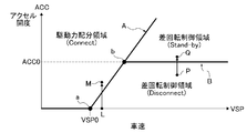
- FIG. It is a basic map figure which shows the drive mode switching map according to the vehicle speed and accelerator opening used by clutch control when the "auto mode" of Example 1 is selected.
- FIG. 1 is a drive system configuration diagram illustrating a drive system configuration of a front wheel drive-based four-wheel drive vehicle to which a clutch control device according to a first embodiment is applied.
- 1 is a control system configuration diagram showing a control system configuration of a front wheel drive-based four-wheel drive vehicle to which a clutch control device of Example 1 is applied.
- FIG. It is a basic map figure which shows the drive mode switching map according to the vehicle speed and accelerator opening used by clutch control when the "auto
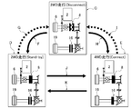
- FIG. 6 is a drive mode transition diagram showing a switching transition of drive modes (disconnect two-wheel drive mode, standby two-wheel drive mode, and connect four-wheel drive mode) by clutch control when “auto mode” of the first embodiment is selected.
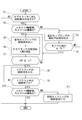
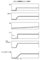
- . 3 is a flowchart illustrating a flow of clutch control processing executed by the 4WD control unit according to the first embodiment. Accelerator opening (ACC), engine torque, vehicle speed (VSP), dog clutch release when the dog clutch is requested to be engaged when switching from "Disconnect 2-wheel drive mode" to "Connect 4-wheel drive mode” / It is a time chart which shows each characteristic of a fastening state, a coupling transmission torque (TETS), and a clutch chamber oil amount.
- ACC Accelerator opening
- VSP vehicle speed
- TETS coupling transmission torque
- ACC Accelerator opening
- VSP vehicle speed
- TETS coupling transmission torque
- TETS coupling transmission torque
- clutch chamber oil amount It is a drive system block diagram which shows the drive system structure of the four-wheel drive vehicle of the rear-wheel drive base to which the clutch control apparatus of Example 2 was applied.
- the configuration of the clutch control device of the front wheel drive-based four-wheel drive vehicle (an example of a four-wheel drive vehicle) in the first embodiment is referred to as “four-wheel drive vehicle drive system configuration”, “four-wheel drive vehicle control system configuration”, The description is divided into “drive mode switching configuration” and “clutch control configuration”.
- FIG. 1 shows a drive system configuration of a front wheel drive-based four-wheel drive vehicle to which a clutch control device is applied.
- the drive system configuration of the four-wheel drive vehicle will be described with reference to FIG.
- the front wheel drive system of the four-wheel drive vehicle includes a horizontally mounted engine 1 (drive source), a transmission 2, a front differential 3, a left front wheel drive shaft 4, and a right front wheel drive shaft 5. And a left front wheel 6 (main drive wheel) and a right front wheel 7 (main drive wheel). That is, the driving force that has passed through the horizontally mounted engine 1 and the transmission 2 is transmitted to the left and right front wheel drive shafts 4 and 5 via the front differential 3, and always drives the left and right front wheels 6 and 7 while allowing the differential.
- a horizontally mounted engine 1 drive source
- a transmission 2 a transmission 2
- a front differential 3 a left front wheel drive shaft 4
- a right front wheel 7 main drive wheel
- the rear wheel drive system of the four-wheel drive vehicle includes a dog clutch 8 (meshing clutch), a bevel gear 9, an output pinion 10, a rear wheel output shaft 11, and a propeller shaft 12.
- the dog clutch 8 and the electric coupling 16 By releasing the dog clutch 8 and the electric coupling 16, the drive system rotation (rotation of the propeller shaft 12 and the like) on the downstream side of the dog clutch 8 is stopped. Improvement is achieved.
- the dog clutch 8 is provided at a driving branch position from the left and right front wheels 6, 7 to the left and right rear wheels 19, 20. This is a meshing clutch that is disconnected from the driving force transmission system.
- the input side meshing member of the dog clutch 8 is coupled to the differential case of the front differential 3, and the output side meshing member of the dog clutch 8 is coupled to the bevel gear 9.
- the dog clutch 8, the bevel gear 9, the output pinion 10, and a part of the rear wheel output shaft 11 are built in a transfer case 23 fixed at a position adjacent to the front differential housing 22.
- the dog clutch 8 for example, one of a pair of meshing members is a fixed member and the other is a movable member.
- a spring that biases in the fastening direction is provided between the fixed member and the movable member, and a solenoid is provided on the outer periphery of the movable member.
- a screw groove that can be fitted with a pin is used.
- the electric control coupling 16 is a friction clutch that is provided downstream of the dog clutch 8 and distributes a part of the driving force from the horizontally mounted engine 1 to the left and right rear wheels 19 and 20 in accordance with the clutch fastening capacity.
- the input side clutch plate of the electric control coupling 16 is connected to the left side gear of the rear differential 15, and the output side clutch plate is connected to the left rear wheel drive shaft 17.
- the electric control coupling 16 is built in a coupling case 25 fixed at a position adjacent to the rear differential housing 24.
- this electric control coupling 16 for example, a multi-plate friction clutch in which a plurality of plates on the input side and the output side are alternately arranged, a fixed cam piston and a movable cam piston having opposing cam surfaces, and an interval between the opposing cam surfaces And a cam member interposed between them.
- the electric control coupling 16 When the electric control coupling 16 is engaged, if the movable cam piston is rotated by an electric motor, the movable cam piston strokes in the clutch engagement direction according to the rotation angle by the cam action that enlarges the piston interval, and the multi-plate friction clutch This is done by increasing the frictional fastening force.
- the electric control coupling 16 includes a multi-plate friction clutch 16a, a clutch chamber 16b, a partition wall 16c, an oil chamber 16d, an oil passage 16e, and an on-off valve 16f. And having.
- the clutch chamber 16b houses the multi-plate friction clutch 16a.
- the oil chamber 16d is a separate chamber defined from the clutch chamber 16b via the partition wall 16c.
- the oil passage 16e communicates the clutch chamber 16b and the oil chamber 16d, and flows oil from the clutch chamber 16b to the oil chamber 16d by centrifugal force.
- the on-off valve 16f is provided on the partition wall 16c, and is configured to open and close in conjunction with the stroke operation of the movable cam piston so as to close at the fully released position of the movable cam piston and open at a position away from the fully released position. . That is, when the electric control coupling 16 is released and the on-off valve 16f is closed, the oil in the clutch chamber 16b flows into the oil chamber 16d by centrifugal force, and the oil is stored in the oil chamber 16d. When the on-off valve 16f is opened, the oil in the oil chamber 16d flows into the clutch chamber 16b. In this way, when the electric control coupling 16 is released (for example, when “standby two-wheel drive mode” is selected), the oil agitation resistance is suppressed.
- FIG. 2 shows a control system configuration of a front wheel drive-based four-wheel drive vehicle to which the clutch control device is applied.
- the control system configuration of the four-wheel drive vehicle will be described with reference to FIG.
- the control system of the four-wheel drive vehicle includes an engine control module 31, a transmission control module 32, an ABS actuator control unit 33, and a 4WD control unit 34, as shown in FIG.
- the engine control module 31 is a control device for the horizontal engine 1 and receives detection signals from the engine speed sensor 35, the accelerator opening sensor 36, and the like. From the engine control module 31, engine speed information and accelerator opening information (ACC information) are input to the 4WD control unit 34 via the CAN communication line 37.
- the transmission control module 32 is a control device for the transmission 2, and receives detection signals from the transmission input rotational speed sensor 38, the transmission output rotational speed sensor 39, and the like.
- Gear ratio information (gear ratio information) is input from the transmission control module 32 to the 4WD control unit 34 via the CAN communication line 37.
- the ABS actuator control unit 33 is a control device for an ABS actuator that controls the brake fluid pressure of each wheel.
- the detection signal from is input.
- yaw rate information, lateral G information, front and rear G information, and wheel speed information of each wheel are input to the 4WD control unit 34 via the CAN communication line 37.
- steering angle information is input from the steering angle sensor 47 to the 4WD control unit 34 via the CAN communication line 37.
- the average value of the left and right rear wheel speed information is used as vehicle speed information (VSP information).
- the 4WD control unit 34 is an engagement / release control device for the dog clutch 8 and the electric control coupling 16, and performs arithmetic processing based on various input information. Then, a drive control command is output to the dog clutch actuator 48 (solenoid) and the electric coupling actuator 49 (electric motor).
- a drive control command is output to the dog clutch actuator 48 (solenoid) and the electric coupling actuator 49 (electric motor).
- input information sources other than the CAN communication line 37 a drive mode selection switch 50, a brake switch 51 for detecting the presence or absence of a brake operation, a ring gear rotation speed sensor 52, a dog clutch stroke sensor 53, a motor rotation angle sensor 54, and the like.
- the drive mode selection switch 50 is a switch for the driver to select and select “2WD mode”, “lock mode”, and “auto mode”.
- “2WD mode” the front-wheel drive 2WD state in which the dog clutch 8 and the electric coupling 16 are released is maintained.
- the “lock mode” the complete 4WD state in which the dog clutch 8 and the electric coupling 16 are engaged is maintained.
- the “auto mode” the engagement / release of the dog clutch 8 and the electric coupling 16 is automatically controlled according to the vehicle state (vehicle speed VSP, accelerator opening ACC).
- the “auto mode” has options of “eco-auto mode” and “sport auto mode”, and “standby two-wheel drive mode” in which the dog clutch 8 is engaged and the electric coupling 16 is released depends on the options. Different. That is, when the “eco-auto mode” is selected, the electronic control coupling 16 is in a fully released state and waits. However, when the “sports auto mode” is selected, the electronic control coupling 16 is in a released state immediately before fastening and waits. .
- the ring gear rotation speed sensor 52 is a sensor for acquiring the output rotation speed information of the dog clutch 8, and by considering the rear side gear ratio and the front side gear ratio in the calculation for the ring gear rotation speed detection value, The output rotational speed of the dog clutch 8 is calculated.
- the input rotation speed information of the dog clutch 8 is acquired by calculating the average value of the left front wheel speed from the left wheel speed sensor 43 and the right front wheel speed from the right wheel speed sensor 44.
- FIG. 3 shows a drive mode switching map according to the vehicle speed VSP and the accelerator opening ACC used in the clutch control when the “auto mode” is selected
- FIG. 4 shows the drive mode (disconnect two-wheel drive mode / (2) Transition transition of standby 2-wheel drive mode / connect 4-wheel drive mode).
- a drive mode switching configuration will be described with reference to FIGS. 3 and 4.
- the drive mode switching map includes a disconnect two-wheel drive mode (Disconnect), a standby two-wheel drive mode (Stand-by), and a connect 4 according to the vehicle speed VSP and the accelerator opening ACC.
- the wheel drive mode (Connect) is set separately.
- the three drive modes are: the zone demarcation line A in which the accelerator depressing amount ACC increases in proportion to the increase in the vehicle speed VSP from the base point a of the set vehicle speed VSP0 with the accelerator depressing point zero, and the intersection b between the region demarcation line A and It is divided by a region dividing line B of a constant accelerator opening ACC0 drawn toward the vehicle speed side.
- the accelerator opening degree ACC is equal to or less than the set opening degree ACC0, and the accelerator opening degree ACC is zero.
- the area is set. In other words, since the accelerator opening ACC is equal to or less than the set opening ACC0, the frequency of occurrence of differential rotation between the left and right front wheels 6 and 7 and the left and right rear wheels 19 and 20 due to driving slip is extremely small, and slip occurs even when driving slip occurs. It is set in the low 4WD request area.
- the accelerator opening ACC exceeds the set opening ACC0 and is set to a high vehicle speed region defined by the region dividing line A and the region dividing line B. That is, since the vehicle speed VSP is in the high vehicle speed range, the 4WD request is low, but the accelerator opening ACC exceeds the set opening ACC0, so the difference between the left and right front wheels 6 and 7 and the left and right rear wheels 19 and 20 due to driving slip. When rotation occurs, it is set in a region where there is a high possibility that the slip will increase rapidly.
- the connect four-wheel drive mode (Connect) is set in a low vehicle speed region surrounded by an accelerator opening axis line where the vehicle speed VSP is zero, a vehicle speed axis line where the accelerator opening ACC is zero, and a region division line A. . That is, it is set in a region where the 4WD request is high, such as when the vehicle starts or when the vehicle speed VSP is low but the accelerator opening degree ACC is high and the load is high.
- the dog clutch 8 and the electric coupling 16 are both released (WD) traveling (Disconnect).
- the front wheel drive 2WD running (Disconnect) is basically maintained by transmitting the drive force only to the left and right front wheels 6 and 7.
- the electric coupling 16 is frictionally engaged.
- the dog clutch 8 is engaged and fastened, and the driving force is distributed to the left and right rear wheels 19 and 20, thereby performing differential rotation control of the front and rear wheels to suppress driving slip.
- the 4WD running (Connect) is performed in which the dog clutch 8 and the electric coupling 16 are both fastened.
- the optimal driving force distribution according to the road surface condition is basically applied to the left and right front wheels 6 and 7 and the left and right rear wheels 19 and 20 (for example, start control and accelerator opening correspondence) Driving force distribution control is performed.
- the turning state of the vehicle is determined based on information from the steering rudder angle sensor 47, the yaw rate sensor 40, the lateral G sensor 41, and the longitudinal G sensor 42 during 4WD traveling, the fastening capacity of the electric control coupling 16 is increased. Control is performed to reduce the tight corner braking phenomenon.
- the switching transition between the 2WD travel (Disconnect), the 2WD travel (Stand-by), and the 4WD travel (Connect) is determined by the operating point determined by the vehicle speed VSP and the accelerator opening ACC. This is performed by a drive mode switching request output when crossing B.
- the transition speed to the drive mode that responds to the 4WD request is determined to have priority over the transition speed to the disconnect two-wheel drive mode that responds to the fuel efficiency request. That is, the switching transition speed (arrow F in FIG. 4) of 2WD traveling (Disconnect) ⁇ 2WD traveling (Stand-by) is increased, and the switching transition speed of 2WD traveling (Stand-by) ⁇ 2WD traveling (Disconnect) (FIG. 4).
- Arrow G is delayed. Similarly, the switching transition speed of 2WD traveling (Disconnect) ⁇ 4WD traveling (Connect) (arrow H in FIG. 4) is increased, and the switching transition speed of 4WD traveling (Connect) ⁇ 2WD traveling (Disconnect) (arrow I in FIG. 4). ) On the other hand, the switching transition speed of 2WD traveling (Stand-by) ⁇ 4WD traveling (Connect) (arrow J in FIG. 4) and the switching transition speed of 4WD traveling (Connect) ⁇ 2WD traveling (Stand-by) (FIG. 4). The arrow K) shows the same high speed.
- FIG. 5 shows a flow of clutch control processing executed by the 4WD control unit 34 (clutch control means).
- the 4WD control unit 34 clutch control means
- step S1 it is determined whether or not there is an engagement request for the dog clutch 8. If YES (there is a fastening request), the process proceeds to step S2. If NO (no fastening request), the process proceeds to the end.
- the engagement request is issued to the dog clutch 8 when the “disconnect two-wheel drive mode” is selected and the mode transition to the “connect four-wheel drive mode” or the “standby two-wheel drive mode”. Is the time.
- step S2 following the determination that there is a fastening request in step S1, it is determined whether or not it is a transition to the connected four-wheel drive mode. If YES (transition to the connected four-wheel drive mode), the process proceeds to step S4. If NO (transition to the standby two-wheel drive mode), the process proceeds to step S3.
- step S3 following the determination that the transition to the “standby two-wheel drive mode” is made in step S2, a command immediately before engagement is output to the coupling actuator 49 of the electric coupling 16, and the process proceeds to step S4.
- the command immediately before the engagement of the electric control coupling 16 is a command for maintaining the release state immediately before the electric control coupling 16 is engaged, and a command for opening the closed on-off valve 16f.
- step S4 whether or not the timer value T started from the time when the engagement request is issued to the dog clutch 8 is equal to or greater than the set value T0 following the command output immediately before the engagement of the electric coupling 16 in step S3. Determine whether. If YES (T ⁇ T0), the process proceeds to step S4. If NO (T ⁇ T0), the determination in step S3 is repeated.
- the set value T0 indicates that almost all of the lubricating oil transferred to the oil chamber 16d is opened / closed when the open / close valve 16 is opened by setting the released electric control coupling 16 to a state immediately before fastening. The time required to flow into the clutch chamber 16b through the valve 16 is set.
- step S5 it is determined that the state is the transition to the “connect four-wheel drive mode” in step S2, or it is determined that T ⁇ T0 in step S4, or ⁇ N> ⁇ in step S7.
- the fastening command for the coupling actuator 49 is a steep slope command that makes the electric coupling 16 fully engaged in a short time.
- a gentle gradient command is set so that the electric coupling 16 gradually shifts from the released state to the fully engaged state.
- step S6 following the engagement command output of the electric coupling 16 in step S5, a clutch differential rotation ⁇ N which is a differential rotation of the dog clutch 8 is calculated, and the process proceeds to step S7.
- the clutch differential rotation ⁇ N is calculated by subtracting the output rotation speed (calculated value based on the detected value of the ring gear rotation speed) from the input rotation speed (left and right front wheel speed average value) of the dog clutch 8.
- step S7 following the calculation of the clutch differential rotation ⁇ N in step S6, it is determined whether or not the clutch differential rotation ⁇ N is equal to or less than the rotation synchronization determination threshold value ⁇ . If YES ( ⁇ N ⁇ ⁇ ), the process proceeds to step S8. If NO ( ⁇ N> ⁇ ), the process returns to step S6.
- the rotation synchronization determination threshold value ⁇ is a clutch differential rotation value for determining a rotation synchronization state in which the dog clutch 8 can be engaged and engaged, and may be given as a fixed value or a variable value according to the vehicle speed VSP or the like. May be.
- step S8 following the determination that ⁇ N ⁇ ⁇ in step S7 or the clutch engagement incomplete in step S9, an engagement command is output to the clutch actuator 48 of the dog clutch 8. Proceed to S9.
- step S9 following the engagement command output of the dog clutch 8 in step S8, it is determined whether or not the dog clutch 8 has completed meshing engagement. If YES (clutch engagement is complete), the process proceeds to step S10. If NO (clutch engagement is not complete), the process returns to step S8.
- the determination as to whether or not the dog clutch 8 has completed meshing engagement is made based on the stroke information from the dog clutch stroke sensor 53.
- step S10 following the determination that the clutch engagement is complete in step S9, it is determined whether or not it is a transition to the connected four-wheel drive mode. If YES (transition to the connected four-wheel drive mode), the process proceeds to the end. If NO (transition to the standby two-wheel drive mode), the process proceeds to step S11.
- step S11 following the determination that the transition is to the standby two-wheel drive mode in step S10, a release command is output to the coupling actuator 49 of the electric control coupling 16, and the process proceeds to the end.
- “Eco Auto Mode” is selected from among “Auto Modes”
- a command to completely release the electric coupling 16 is used, and when “Sports Auto Mode” is selected, the electric coupling 16 is released immediately before fastening. A command to keep the state.
- step S 1 when an engagement request is issued to the dog clutch 8 when shifting from the “disconnect two-wheel drive mode” to the “connect four-wheel drive mode”, in the flowchart of FIG. 5, step S 1 ⁇ step S 2 ⁇ step S 5 ⁇ step The process proceeds from S6 to step S7.
- step S ⁇ b> when there is a request for engaging the dog clutch 8, an engagement command is immediately output to the coupling actuator 49 of the electric control coupling 16.
- step S6 a clutch differential rotation ⁇ N that is a differential rotation of the dog clutch 8 is calculated.
- step S7 it is determined whether or not the clutch differential rotation ⁇ N is equal to or less than the rotation synchronization determination threshold value ⁇ . Then, while it is determined in step S7 that ⁇ N> ⁇ , the flow of going from step S5 to step S6 to step S7 is repeated.
- step S7 When the rotation synchronization determination condition in step S7 is satisfied, the process proceeds from step S7 to step S8 to step S9 in the flowchart of FIG. 5.
- step S8 an engagement command is output to the clutch actuator 48 of the dog clutch 8. .
- step S9 it is determined whether or not the dog clutch 8 has completed the mesh engagement, and while it is determined that the clutch engagement is not completed, the flow from step S8 to step S9 is repeated. If it is determined in step S9 that the dog clutch 8 has completed meshing engagement, the process proceeds from step S9 to step S10 ⁇ end.
- the released dog clutch 8 starts meshing and engaging.
- the opening / closing valve 16 is opened from the time t1 when the disengaged electric control coupling 16 starts to be engaged, and the flow of the lubricating oil transferred to the oil chamber 16d into the clutch chamber 16b is started.
- time t2 only a small amount of lubricating oil is flowing in, and in this state, the dog clutch 8 is engaged and starts fastening. That is, unless the time t3 comes, all of the lubricating oil transferred to the oil chamber 16d does not flow into the clutch chamber 16b.
- the time from the engagement request time t1 to the dog clutch 8 to the time t2 when the rotation synchronization determination condition is satisfied is short.
- the dog clutch 8 is engaged and fastened only by waiting for the time ⁇ T1.
- the drive mode transition from the “disconnect two-wheel drive mode” to the “connect four-wheel drive mode” is achieved with good response.
- step S 1 when an engagement request is issued to the dog clutch 8 when shifting from the “disconnect two-wheel drive mode” to the “standby two-wheel drive mode”, in the flowchart of FIG. 5, step S 1 ⁇ step S 2 ⁇ step S 3 ⁇ Proceed to step S4.
- step S3 a command immediately before the engagement is output to the coupling actuator 49 of the electric coupling 16, and in step S4, the timer value T that is started when the engagement request is issued to the dog clutch 8 is set. It is determined whether or not the value is equal to or greater than T0.
- T ⁇ T0 the flow from step S3 to step S4 is repeated, and the start of fastening of the electric control coupling 16 is awaited.
- step S4 When T ⁇ T0, the process proceeds from step S4 to step S5 ⁇ step S6 ⁇ step S7.
- step S ⁇ b> 5 a fastening command is output to the coupling actuator 49 of the electric control coupling 16.
- step S6 a clutch differential rotation ⁇ N that is a differential rotation of the dog clutch 8 is calculated.
- step S7 it is determined whether or not the clutch differential rotation ⁇ N is equal to or less than the rotation synchronization determination threshold value ⁇ . Then, while it is determined in step S7 that ⁇ N> ⁇ , the flow of going from step S5 to step S6 to step S7 is repeated.
- step S7 When the rotation synchronization determination condition in step S7 is satisfied, the process proceeds from step S7 to step S8 to step S9 in the flowchart of FIG. 5.
- step S8 an engagement command is output to the clutch actuator 48 of the dog clutch 8. .
- step S9 it is determined whether or not the dog clutch 8 has completed the mesh engagement, and while it is determined that the clutch engagement is not completed, the flow from step S8 to step S9 is repeated.
- step S9 When it is determined in step S9 that the dog clutch 8 has completed meshing engagement, the process proceeds from step S9 to step S10 ⁇ step S11 ⁇ end.
- step S11 a release command is output to the coupling actuator 49 of the electric control coupling 16.
- the electric coupling 16 When the “eco-auto mode” is selected, the electric coupling 16 is completely released, and when the “sports auto mode” is selected, the electric coupling 16 is kept in the released state immediately before fastening. .
- the dog clutch 8 is a meshing clutch that meshes with a clutch input / output rotation in a synchronized state, unlike a friction clutch that can be engaged regardless of whether or not there is a clutch differential rotation. For this reason, when the "disconnect two-wheel drive mode" in which the dog clutch 8 is released is selected, if there is a request to engage the dog clutch 8, the electric coupling 16 is engaged and the input / output rotation of the dog clutch 8 is performed. It is necessary to be in a synchronized rotation state.
- a “standby two-wheel drive mode” in which only the dog clutch 8 is engaged is added to the “disconnect two-wheel drive mode” and the “connect four-wheel drive mode”.
- the dog clutch 8 is requested to be engaged when switching from “disconnect two-wheel drive mode” to “connect four-wheel drive mode” and from “disconnect two-wheel drive mode” to “standby two-wheel drive mode”.
- any drive mode switching if the timing from the engagement request of the dog clutch 8 to the start of the engagement of the electric control coupling 16 is uniquely set, the following problems occur.
- the synchronization timing is varied depending on the drive mode of the transition destination.
- the fastening start timing of the electric control coupling 16 when shifting to the “connect four-wheel drive mode” is set to an earlier timing than when shifting to the “standby two-wheel drive mode”.
- the “disconnect two-wheel drive mode” is a two-wheel drive with high energy-saving performance that stops the rotation of the driving force transmission system from the dog clutch 8 to the electric control coupling 16 to the left and right rear wheels 19 and 20 and suppresses friction loss.
- Drive mode The “connect four-wheel drive mode” is a four-wheel drive mode with high drive performance that distributes the driving force from the horizontally placed engine 1 to the four wheels when acceleration is requested.
- the “standby two-wheel drive mode” is a two-wheel drive mode in which the transition response to the four-wheel drive state is improved compared to the “disconnect two-wheel drive mode” by fastening the dog clutch 8 in advance.
- the electric control coupling 16 is performed at a later timing (time t3 in FIG. 7) when the clutch chamber 16b is filled with the lubricating oil. The conclusion of is started. For this reason, unless a long time (time t1 to t3 in FIG. 7) is waited for from the fastening request, the rotation synchronization state is not achieved, and the travel range by the “disconnect two-wheel drive mode” is substantially expanded. Energy saving performance (fuel consumption effect) is ensured. As a result, when the dog clutch 8 is requested to be engaged, it is possible to ensure both the four-wheel drive performance and the energy-saving performance.
- the “disconnect two-wheel drive mode” is set to a low accelerator opening range and a high vehicle speed range, and the “standby two-wheel drive mode” is set to a high accelerator opening range and a high vehicle speed range.
- the “four-wheel drive mode” is set to the entire accelerator opening and the low vehicle speed range. That is, switching from the “disconnect two-wheel drive mode” to the “connect four-wheel drive mode” is performed in a low vehicle speed range and a low accelerator opening range (see FIG. 3).
- the electric coupling 16 includes a clutch chamber 16b, an oil chamber 16d defined from the clutch chamber 16b via a partition wall 16c, an oil passage 16e communicating the clutch chamber 16b and the oil chamber 16d, And an on-off valve 16f provided on the partition wall 16c. Then, when there is a fastening request for the dog clutch 8 at the time of switching to the “connect four-wheel drive mode”, without waiting for the oil in the oil chamber 16d to flow into the clutch chamber 16b via the on-off valve 16f, The configuration is such that the fastening of the electric coupling 16 is started immediately. That is, when the engagement of the electric coupling 16 is started in a state where the clutch chamber 16b is filled with oil, the agitation resistance due to the oil is large.
- the dog clutch 8 when the dog clutch 8 is requested to be engaged when switching to the “standby two-wheel drive mode”, it waits for the oil in the oil chamber 16d to flow into the clutch chamber 16b via the on-off valve 16f.
- the fastening of the electric control coupling 16 is started. That is, when the fastening of the electric control coupling 16 is started in a state where the clutch chamber 16b is not filled with oil, the oil lubrication effect cannot be obtained and the frictional resistance is large, so that the deterioration of the electric control coupling 16 is accelerated.
- the fastening of the electric control coupling 16 is started in a state where the oil is filled in the clutch chamber 16b, an oil lubrication effect is obtained.
- the dog clutch 8 is disposed upstream of the bevel gear 9 and the output pinion 10 provided at the driving branch position to the left and right front wheels 6, 7.
- the electric control coupling 16 drives the left rear wheel from the bevel gear 9 and the output pinion 10 to the left rear wheel 19 via the rear wheel output shaft 11, the propeller shaft 12 and the drive pinion 13, the ring gear 14, and the rear differential 15.
- the structure is arranged at the position of the shaft 17.
- One of the left and right front wheels 6 and 7 and the left and right rear wheels 19 and 20 is a main drive wheel connected to a drive source (horizontal engine 1), and the other is a clutch to the drive source (horizontal engine 1). And a sub-drive wheel connected through Of the driving force transmission systems to the auxiliary driving wheels (left and right rear wheels 19, 20), the clutch is connected to the transmission branch path on the driving branch side and the transmission transmission path on the auxiliary driving wheel side across the differential (rear differential 15), respectively.
- a meshing clutch (dog clutch 8) and a friction clutch (electric coupling 16) arranged separately are provided,
- the meshing clutch (dog clutch 8) separates the driving force transmission system to the auxiliary driving wheels (left and right rear wheels 19 and 20) from the driving force transmission system to the main driving wheels (left and right front wheels 6 and 7) by releasing the clutch.
- the clutch (electric control coupling 16) is a four-wheel drive vehicle that distributes a part of the driving force from the drive source (horizontal engine 1) to the auxiliary drive wheels (left and right rear wheels 19, 20) according to the clutch engagement capacity.
- the engagement clutch (dog clutch 8) is brought into a rotationally synchronized state by engaging the friction clutch (electric coupling 16), and then the engagement clutch (dog clutch 8) in the released state is engaged.
- clutch control means (4WD control unit 34, FIG. 5) for performing control for starting the engagement of In a four-wheel drive vehicle, a “disconnect two-wheel drive mode” that releases the mesh clutch (dog clutch 8) and the friction clutch (electric coupling 16), and the mesh clutch (dog clutch 8) are engaged and the friction clutch (electric cup).
- the clutch control means (4WD control unit 34, FIG. 5) shifts to “connect four-wheel drive mode” when there is a request for engagement with the mesh clutch (dog clutch 8) in the selected state of “disconnect two-wheel drive mode”.
- the engagement start timing of the friction clutch (electric coupling 16) is set to an earlier timing as compared to the transition to the “standby two-wheel drive mode” (FIG. 5). For this reason, when the engagement clutch (dog clutch 8) is requested to be engaged, it is possible to achieve both of ensuring the four-wheel drive performance and ensuring the energy saving performance.
- the clutch control means (4WD control unit 34, FIG. 5) sets the “disconnect two-wheel drive mode” to a low accelerator opening range and a high vehicle speed range, and opens the “standby two-wheel drive mode” to a high accelerator.
- the range is set to the high vehicle speed range
- the “connect four-wheel drive mode” is set to the entire accelerator opening and the low vehicle speed range (FIG. 3). Therefore, in addition to the effect of (1), when switching from “Disconnect 2-wheel drive mode” to “Connect 4-wheel drive mode”, the friction clutch (electric control coupling 16) has a small load, so that The rotation synchronization of the clutch (dog clutch 8) can be completed earlier.
- the friction clutch (electric coupling 16) includes a clutch chamber 16b that houses the multi-plate friction clutch 16a, an oil chamber 16d that is defined by a partition wall 16c from the clutch chamber 16b, a clutch chamber 16b, An oil passage 16e that communicates with the oil chamber 16d and flows oil from the clutch chamber 16b to the oil chamber 16d by centrifugal force; and an on-off valve 16f provided on the partition wall 16c.
- the clutch control means (4WD control unit 34, FIG. 5) is requested to be engaged with the meshing clutch when switching from the “disconnect two-wheel drive mode” to the “connect four-wheel drive mode”, the oil chamber 16d.
- the clutch control means (4WD control unit 34, FIG. 5) makes an engagement request to the mesh clutch (dog clutch 8) when switching from the “disconnect two-wheel drive mode” to the “standby two-wheel drive mode”.
- it waits for the oil in the oil chamber 16d to flow into the clutch chamber 16b via the on-off valve 16f, and then the engagement of the friction clutch (electric coupling 16) is started (FIG. 7).
- an oil lubrication effect for fastening of the friction clutch (electric coupling 16) can be obtained when switching from the “disconnect two-wheel drive mode” to the “standby two-wheel drive mode”.
- the meshing clutch (dog clutch 8) is disposed upstream of the transfer mechanism (bevel gear 9, output pinion 10) provided at the driving branch position to the auxiliary driving wheels (left and right rear wheels 19, 20).
- the friction clutch (electric coupling 16) is connected to the drive shaft (left rear wheel 19) from the transfer mechanism (bevel gear 9, output pinion 10) via the propeller shaft 12 and the differential (rear differential 15). It is arranged at the position of the rear wheel drive shaft 17) (FIG. 1). For this reason, in addition to the effects (1) to (4), friction loss and oil agitation loss are effective when the “disconnect two-wheel drive mode” is selected in the four-wheel drive vehicle based on the front wheel drive. It can be suppressed and fuel consumption can be improved.
- the second embodiment is an example in which a clutch control device is applied to a four-wheel drive vehicle based on a rear wheel drive, and the disposition relationship between the meshing clutch and the friction clutch sandwiching the differential is opposite to that of the first embodiment. .
- FIG. 8 shows a drive system configuration of a rear-wheel drive-based four-wheel drive vehicle to which the clutch control device is applied.
- the drive system configuration of the four-wheel drive vehicle will be described with reference to FIG.
- the rear wheel drive system of the four-wheel drive vehicle includes a longitudinal engine 61 (drive source), a transmission 62, a rear propeller shaft 63, a rear differential 64, and a left rear wheel drive shaft. 65, a right rear wheel drive shaft 66, a left rear wheel 67 (main drive wheel), and a right rear wheel 68 (main drive wheel). That is, the driving force that has passed through the vertical engine 61 and the transmission 62 is transmitted to the left and right rear wheel drive shafts 65 and 66 via the rear propeller shaft 63 and the rear differential 64, and allows the left and right rear wheels 67 while allowing the differential. , 68 are always driven.
- the front wheel drive system of the four-wheel drive vehicle includes an electric control coupling 70 (friction clutch), an input side sprocket 71, an output side sprocket 72, a chain 73, and a transfer case 69. And a transfer mechanism is configured. Then, a front propeller shaft 74, a front differential 75, a left front wheel drive shaft 76, a right front wheel drive shaft 77, a left front wheel 78 (sub driving wheel), and a right front wheel 79 (sub driving wheel) connected to the output side sprocket 72. Drive wheel).
- the electric control coupling 70 is disposed in the transfer case 69 at an upstream position (main drive system side position) from the input side sprocket 71.
- the drive system rotation rotation of the front propeller shaft 74, etc.
- the electric coupling 70 stops, so that friction loss, oil agitation loss, etc. Suppressed and improved fuel efficiency.
- the dog clutch 8 is arranged on the transmission branch side transmission path between which the rear differential 15 is sandwiched, and the auxiliary driving wheel side
- the electric transmission coupling 16 is separately arranged in the transmission system path. For this reason, when there is a fastening request for the dog clutch 8 in the released state, if the fastening control of the electric coupling 16 is performed, the left side gear of the rear differential 15 is restrained by the rotational speed of the left rear wheel 19.
- the clutch differential rotation ⁇ N that has decreased with the passage of time becomes a limit when it reaches a certain differential rotation, and thereafter, the clutch differential rotation ⁇ N shifts to increase, As the time elapses, the clutch differential rotation ⁇ N increases.
- the electric coupling 70 is arranged on the transmission system on the driving branch side with the front differential 75 interposed therebetween.
- the dog clutch 80 is arranged separately on the transmission path on the auxiliary drive wheel side. For this reason, when there is an engagement request for the dog clutch 80 in the released state, if the engagement control of the electric coupling 70 is performed, the differential case of the front differential 75 is constrained by the rotational speed of the rear propeller shaft 63.
- the rotational speed of the right side gear (the right front wheel 79) and the differential case is constrained, so that the rotational speed of the left side gear becomes two rotational speeds. It will be decided by.
- the friction clutch (electric control coupling 70) is upstream of the transfer mechanism (input-side sprocket 71, output-side sprocket 72, chain 73) provided at the driving branch position to the auxiliary drive wheels (left and right front wheels 78, 79). Placed in position, The meshing clutch (dog clutch 80) is located at the position of the drive shaft (left front wheel drive shaft 76) from the transfer mechanism to the sub drive wheel (left front wheel 78) via the propeller shaft (front propeller shaft) and the differential (front differential 75). Deploy.
- Example 1 an example in which the dog clutch 8 is arranged at the upstream position of the transfer mechanism as the meshing clutch is shown.
- the meshing clutch may be an example in which a dog clutch is disposed at a position downstream of the transfer mechanism and at the position of the propeller shaft.
- the electric control coupling 16 is disposed in the middle of the left rear wheel drive shaft 17 as a friction clutch.
- the friction clutch may be an example in which an electric control coupling is disposed in the middle of the right rear wheel drive shaft.
- Example 1 shows an example in which the clutch control device of the present invention is applied to a front-wheel drive-based four-wheel drive vehicle (4WD engine vehicle) equipped with an engine as a drive source.
- the clutch control device of the present invention is applied to a rear wheel drive-based four-wheel drive vehicle (4WD engine vehicle) in which the main drive wheels are the left and right rear wheels.
- the present invention can be applied to a rear wheel drive-based four-wheel drive vehicle in which the disposition relationship between the meshing clutch and the friction clutch is the relationship of the first embodiment.
- the present invention can be applied to a front wheel drive-based four-wheel drive vehicle in which the engagement relationship between the meshing clutch and the friction clutch is the relationship of the second embodiment.
- the present invention can also be applied to a 4WD hybrid vehicle in which an engine and a motor are mounted as a drive source, and a 4WD electric vehicle in which a motor is mounted as a drive source.
Landscapes
- Engineering & Computer Science (AREA)
- Mechanical Engineering (AREA)
- General Engineering & Computer Science (AREA)
- Chemical & Material Sciences (AREA)
- Combustion & Propulsion (AREA)
- Transportation (AREA)
- Arrangement And Mounting Of Devices That Control Transmission Of Motive Force (AREA)
- Mechanical Operated Clutches (AREA)
- Arrangement And Driving Of Transmission Devices (AREA)
Abstract
Description
前記クラッチとして、前記副駆動輪への駆動力伝達系のうち、デファレンシャルを挟んだ駆動分岐側の伝達系路と副駆動輪側の伝達系路にそれぞれ分けて配置される噛み合いクラッチと摩擦クラッチを備える。
前記噛み合いクラッチは、クラッチ解放により前記副駆動輪への駆動力伝達系を、前記主駆動輪への駆動力伝達系から切り離し、前記摩擦クラッチは、クラッチ締結容量に応じて前記駆動源からの駆動力の一部を前記副駆動輪へ配分する。
この4輪駆動車において、前記噛み合いクラッチに対し締結要求があったとき、前記摩擦クラッチの締結により前記噛み合いクラッチを回転同期状態にした後、解放状態の前記噛み合いクラッチの締結を開始する制御を行うクラッチ制御手段を設ける。
前記4輪駆動車は、前記噛み合いクラッチと前記摩擦クラッチを解放するディスコネクト2輪駆動モードと、前記噛み合いクラッチを締結し前記摩擦クラッチを解放するスタンバイ2輪駆動モードと、前記噛み合いクラッチと前記摩擦クラッチを締結するコネクト4輪駆動モードと、を有する。
前記クラッチ制御手段は、前記ディスコネクト2輪駆動モードの選択状態で前記噛み合いクラッチに対し締結要求があったとき、前記コネクト4輪駆動モードへ移行するときの前記摩擦クラッチの締結開始タイミングを、前記スタンバイ2輪駆動モードへ移行するときに比べ早期タイミングにする。
すなわち、「ディスコネクト2輪駆動モード」は、噛み合いクラッチから摩擦クラッチまでの副駆動輪への駆動力伝達系の回転を止めてフリクション損失等を抑える省エネ性能が高い2輪駆動モードである。「コネクト4輪駆動モード」は、加速要求時等において駆動源からの駆動力を4輪に配分する駆動性能が高い4輪駆動モードである。「スタンバイ2輪駆動モード」は、「ディスコネクト2輪駆動モード」に比べ4輪駆動状態への移行応答性を高めた2輪駆動モードである。そして、噛み合いクラッチに対し締結要求があったときには、摩擦クラッチの締結により噛み合いクラッチの入出力回転を同期状態にする必要がある。
これに対し、4輪駆動状態への切り替え移行は、2輪駆動状態を維持する切り替え移行に比べ応答性が要求される点に着目し、「ディスコネクト2輪駆動モード」から「コネクト4輪駆動モード」へ切り替え移行するときは、早期タイミングにて摩擦クラッチの締結が開始される。このため、締結要求から早く回転同期状態となり、4輪駆動モードへの切り替え応答性が確保される。一方、「ディスコネクト2輪駆動モード」から「スタンバイ2輪駆動モード」へ切り替え移行するときは、遅いタイミングにて摩擦クラッチの締結が開始される。このため、締結要求から長い時間を待たないと回転同期状態とはならず、「ディスコネクト2輪駆動モード」による走行域が実質的に拡大することになり、省エネ性能が確保される。
この結果、噛み合いクラッチの締結要求時、4輪駆動性能の確保と省エネ性能の確保との両立を図ることができる。
実施例1における前輪駆動ベースの4輪駆動車(4輪駆動車の一例)のクラッチ制御装置の構成を、「4輪駆動車の駆動系構成」、「4輪駆動車の制御系構成」、「駆動モード切り替え構成」、「クラッチ制御構成」に分けて説明する。
図1は、クラッチ制御装置が適用された前輪駆動ベースの4輪駆動車の駆動系構成を示す。以下、図1に基づき、4輪駆動車の駆動系構成を説明する。
すなわち、ドグクラッチ8と電制カップリング16を共に解放する2輪駆動モード(=ディスコネクト2輪駆動モード)を選択することが可能な駆動系構成としている。このドグクラッチ8と電制カップリング16を解放することにより、ドグクラッチ8より下流側の駆動系回転(プロペラシャフト12等の回転)が停止することで、フリクション損失やオイル攪拌損失などが抑えられ、燃費向上が達成される。
図2は、クラッチ制御装置が適用された前輪駆動ベースの4輪駆動車の制御系構成を示す。以下、図2に基づき、4輪駆動車の制御系構成を説明する。
図3は、「オートモード」が選択されたときのクラッチ制御で用いられる車速VSPとアクセル開度ACCに応じた駆動モード切り替えマップを示し、図4は、駆動モード(ディスコネクト2輪駆動モード・スタンバイ2輪駆動モード・コネクト4輪駆動モード)の切り替え遷移を示す。以下、図3及び図4に基づき、駆動モード切り替え構成を説明する。
すなわち、2WD走行(Disconnect)→2WD走行(Stand-by)の切り替え遷移速度(図4の矢印F)を早くし、2WD走行(Stand-by)→2WD走行(Disconnect)の切り替え遷移速度(図4の矢印G)を遅くしている。同様に、2WD走行(Disconnect)→4WD走行(Connect)の切り替え遷移速度(図4の矢印H)を早くし、4WD走行(Connect)→2WD走行(Disconnect)の切り替え遷移速度(図4の矢印I)を遅くしている。これに対し、2WD走行(Stand-by)→4WD走行(Connect)の切り替え遷移速度(図4の矢印J)と、4WD走行(Connect)→2WD走行(Stand-by)の切り替え遷移速度(図4の矢印K)は、同じ早い速度にしている。
図5は、4WDコントロールユニット34にて実行されるクラッチ制御処理流れを示す(クラッチ制御手段)。以下、クラッチ制御処理構成をあらわす図5の各ステップについて説明する。このフローチャートは、「オートモード」の選択時であり、かつ、駆動モードとして、ドグクラッチ8と電制カップリング16が共に解放されている「ディスコネクト2輪駆動モード」が選択されているときに開始される。
ここで、ドグクラッチ8に対し締結要求が出されるのは、「ディスコネクト2輪駆動モード」の選択時、「コネクト4輪駆動モード」又は「スタンバイ2輪駆動モード」へのモード遷移と判定されたときである。
ここで、電制カップリング16の締結直前指令とは、電制カップリング16が締結直前の解放状態を保つ指令であり、閉じていた開閉弁16fを開くための指令である。
ここで、設定値T0は、解放状態の電制カップリング16を締結直前状態にすることにより開閉弁16が開いたとき、オイル室16dに移送されている潤滑オイルのほぼ全てが、開いた開閉弁16を介してクラッチ室16bへ流れ込むのに要する時間に設定される。
ここで、カップリングアクチュエータ49に対する締結指令は、「コネクト4輪駆動モード」への遷移の場合、短時間にて電制カップリング16が完全締結状態となる急勾配指令とし、「スタンバイ2輪駆動モード」への遷移の場合、電制カップリング16が解放状態から完全締結状態へと徐々に移行する緩勾配指令としている。
ここで、クラッチ差回転ΔNは、ドグクラッチ8の入力回転数(左右前輪速平均値)から出力回転数(リングギア回転数検出値に基づく演算値)を差し引くことで演算される。
ここで、回転同期判定閾値αは、ドグクラッチ8の噛み合い締結が可能な回転同期状態を判定するクラッチ差回転値であり、固定値で与えても良いし、車速VSP等に応じた可変値で与えても良い。
ここで、ドグクラッチ8が噛み合い締結を完了したか否かの判断は、ドグクラッチストロークセンサ53からのストローク情報に基づいて行う。
ここで、「オートモード」のうち、「エコオートモード」の選択時には、電制カップリング16を完全解放する指令とし、「スポーツオートモード」の選択時には、電制カップリング16を締結直前の解放状態を保つ指令とする。
実施例1の4輪駆動車のクラッチ制御装置における作用を、「ドグクラッチの締結制御作用」、「ドグクラッチの同期開始タイミング制御作用」、「ドグクラッチ締結制御での他の特徴作用」に分けて説明する。
まず、図5のフローチャートに基づき、ドグクラッチ8の締結制御処理動作の流れを説明する。例えば、「ディスコネクト2輪駆動モード」が選択されている低車速域でのアクセル足放しコースト走行中、アクセル踏み込み操作により、動作点が図3のL点からM点へ移動したとき、領域区分線Aを横切るタイミングでドグクラッチ8に対し締結要求が出される。又は、「ディスコネクト2輪駆動モード」が選択されている高車速域でのドライブ走行中、アクセル踏み増し操作により、動作点が図3のP点からQ点へ移動したとき、領域区分線Bを横切るタイミングでドグクラッチ8に対し締結要求が出される。
時刻t1にてアクセル開度ACCが立ち上がり、ドグクラッチ8に対し締結要求が出されると、時刻t1のタイミングにて電制カップリング16の締結が開始されることにより、カップリング伝達トルクが立ち上がりを開始し、停止していたプロペラシャフト12が回転を開始する。これにより、クラッチ差回転ΔNが低下を開始する。
時刻t1にてアクセル開度ACCが踏み増しされ、ドグクラッチ8に対し締結要求が出されると、時刻t1のタイミングにおいて、電制カップリング16を解放したままで開閉弁16fが開く。このため、時刻t1にてオイル室16dに移送されている潤滑オイルが、クラッチ室16bへの流れ込みを開始する。時刻t2では、電制カップリング16を解放したままで開閉弁16fが開いた状態が継続され、時刻t3になると、オイル室16dに移送されている潤滑オイルの全てがクラッチ室16bへ流れ込む。なお、時刻t1から時刻t2までがタイマー値Tの設定値T0に相当する。
ドグクラッチ8は、クラッチ差回転の有無に関係なく締結できる摩擦クラッチとは異なり、クラッチ入出力回転を同期状態にして噛み合わせる噛み合いクラッチである。このため、ドグクラッチ8が解放されている「ディスコネクト2輪駆動モード」が選択されているとき、ドグクラッチ8の締結要求があると、電制カップリング16を締結してドグクラッチ8の入出力回転を同期回転状態にする必要がある。
(a) 燃費性能を狙って、ドグクラッチ8の締結要求から電制カップリング16の締結開始までのタイミングを遅くすると、「コネクト4輪駆動モード」への切り替え応答性が悪化し、4輪駆動性能への跳ね返りが懸念される。
(b) 逆に、「コネクト4輪駆動モード」への切り替え応答性を狙って、ドグクラッチ8の締結要求から電制カップリング16の締結開始までのタイミングを早くすると、燃費効果が高い「ディスコネクト2輪駆動モード」での走行域が縮小してしまう。
実施例1では、「ディスコネクト2輪駆動モード」を低アクセル開度域かつ高車速域に設定し、「スタンバイ2輪駆動モード」を高アクセル開度域かつ高車速域に設定し、「コネクト4輪駆動モード」をアクセル開度全域かつ低車速域に設定する構成とした。
すなわち、「ディスコネクト2輪駆動モード」から「コネクト4輪駆動モード」への切り替えは、低車速域かつ低アクセル開度域で行われる(図3参照)。この低車速域かつ低アクセル開度域は、電制カップリング16への負荷が小さく、潤滑オイルがクラッチ室16b側へ完全に流れるのを待たずして回転同期を開始できる。一方、「ディスコネクト2輪駆動モード」から「スタンバイ2輪駆動モード」への切り替えは、高車速域かつ高アクセル開度域で行われる(図3参照)。この高車速域かつ高アクセル開度域は、電制カップリング16への負荷が大きい。
したがって、「ディスコネクト2輪駆動モード」から「コネクト4輪駆動モード」への切り替え時、電制カップリング16への負荷が小さいことで、ドグクラッチ8の回転同期をより早く完了することができる。
すなわち、クラッチ室16bにオイルが満たされている状態で電制カップリング16の締結を開始すると、オイルによる攪拌抵抗が大きい。これに対し、クラッチ室16bにオイルが満たされていない状態で電制カップリング16の締結を開始すると、オイルによる攪拌抵抗が小さくなる。
したがって、「ディスコネクト2輪駆動モード」から「コネクト4輪駆動モード」への切り替え時、電制カップリング16の締結によるオイルによる攪拌抵抗が小さいことで、ドグクラッチ8の回転同期をより早く完了することができる。
すなわち、クラッチ室16bにオイルが満たされていない状態で電制カップリング16の締結を開始すると、オイル潤滑効果が得られなく摩擦抵抗が大きいことで、電制カップリング16の劣化を早める。これに対し、クラッチ室16bにオイルが満たされている状態で電制カップリング16の締結を開始すると、オイル潤滑効果が得られる。
したがって、「ディスコネクト2輪駆動モード」から「スタンバイ2輪駆動モード」への切り替え時、電制カップリング16の締結に対するオイル潤滑効果が得られることで、回転同期速度を遅くしても電制カップリング16の耐久信頼性を確保することができる。
この構成により、「ディスコネクト2輪駆動モード」が選択されているとき、ベベルギア9、出力ピニオン10、後輪出力軸11、プロペラシャフト12、ドライブピニオン13、リングギア14、リアデファレンシャル15のデフケースの回転が停止する。
したがって、「ディスコネクト2輪駆動モード」が選択されているとき、ドグクラッチ8から電制カップリング16までの駆動系回転が停止する作用を示し、フリクション損失やオイル攪拌損失などが有効に抑えられ、燃費向上を達成することができる。
実施例1の4輪駆動車のクラッチ制御装置にあっては、下記に列挙する効果を得ることができる。
クラッチとして、副駆動輪(左右後輪19,20)への駆動力伝達系のうち、デファレンシャル(リアデファレンシャル15)を挟んだ駆動分岐側の伝達系路と副駆動輪側の伝達系路にそれぞれ分けて配置される噛み合いクラッチ(ドグクラッチ8)と摩擦クラッチ(電制カップリング16)を備え、
噛み合いクラッチ(ドグクラッチ8)は、クラッチ解放により副駆動輪(左右後輪19,20)への駆動力伝系を、主駆動輪(左右前輪6,7)への駆動力伝達系から切り離し、摩擦クラッチ(電制カップリング16)は、クラッチ締結容量に応じて駆動源(横置きエンジン1)からの駆動力の一部を副駆動輪(左右後輪19,20)へ配分する4輪駆動車において、
噛み合いクラッチ(ドグクラッチ8)に対し締結要求があったとき、摩擦クラッチ(電制カップリング16)の締結により噛み合いクラッチ(ドグクラッチ8)を回転同期状態にした後、解放状態の噛み合いクラッチ(ドグクラッチ8)の締結を開始する制御を行うクラッチ制御手段(4WDコントロールユニット34、図5)を設け、
4輪駆動車は、噛み合いクラッチ(ドグクラッチ8)と摩擦クラッチ(電制カップリング16)を解放する「ディスコネクト2輪駆動モード」と、噛み合いクラッチ(ドグクラッチ8)を締結し摩擦クラッチ(電制カップリング16)を解放する「スタンバイ2輪駆動モード」と、噛み合いクラッチ(ドグクラッチ8)と摩擦クラッチ(電制カップリング16)を締結する「コネクト4輪駆動モード」と、を有し、
クラッチ制御手段(4WDコントロールユニット34、図5)は、「ディスコネクト2輪駆動モード」の選択状態で噛み合いクラッチ(ドグクラッチ8)に対し締結要求があったとき、「コネクト4輪駆動モード」へ移行するときの摩擦クラッチ(電制カップリング16)の締結開始タイミングを、「スタンバイ2輪駆動モード」へ移行するときに比べ早期タイミングにする(図5)。
このため、噛み合いクラッチ(ドグクラッチ8)の締結要求時、4輪駆動性能の確保と省エネ性能の確保との両立を図ることができる。
このため、(1)の効果に加え、「ディスコネクト2輪駆動モード」から「コネクト4輪駆動モード」への切り替え時、摩擦クラッチ(電制カップリング16)への負荷が小さいことで、噛み合いクラッチ(ドグクラッチ8)の回転同期をより早く完了することができる。
クラッチ制御手段(4WDコントロールユニット34、図5)は、「ディスコネクト2輪駆動モード」から「コネクト4輪駆動モード」への切り替えの際に噛み合いクラッチに対し締結要求があったとき、オイル室16dのオイルが開閉弁16fを介してクラッチ室16bに流入するのを待つことなく、直ちに摩擦クラッチ(電制カップリング16)の締結を開始する(図6)。
このため、(1)又は(2)の効果に加え、「ディスコネクト2輪駆動モード」から「コネクト4輪駆動モード」への切り替え時、摩擦クラッチ(電制カップリング16)の締結によるオイルによる攪拌抵抗が小さいことで、噛み合いクラッチ(ドグクラッチ8)の回転同期をより早く完了することができる。
このため、(3)の効果に加え、「ディスコネクト2輪駆動モード」から「スタンバイ2輪駆動モード」への切り替え時、摩擦クラッチ(電制カップリング16)の締結に対するオイル潤滑効果が得られることで、回転同期速度を遅くしても摩擦クラッチ(電制カップリング16)の耐久信頼性を確保することができる。加えて、回転同期速度を遅くした場合、噛み合いクラッチ(ドグクラッチ8)の締結ショックも低く抑えることができる。
摩擦クラッチ(電制カップリング16)は、トランスファ機構(ベベルギア9、出力ピニオン10)からプロペラシャフト12及びデファレンシャル(リアデファレンシャル15)を経由した副駆動輪(左後輪19)へのドライブシャフト(左後輪ドライブシャフト17)の位置に配置する(図1)。
このため、(1)~(4)の効果に加え、前輪駆動ベースの4輪駆動車において、「ディスコネクト2輪駆動モード」が選択されているとき、フリクション損失やオイル攪拌損失などが有効に抑えられ、燃費向上を達成することができる。
すなわち、電制カップリング70とドグクラッチ80を共に解放する2輪駆動モード(=ディスコネクト2輪駆動モード)を選択することが可能な駆動系構成としている。この電制カップリング70とドグクラッチ80を解放することにより、電制カップリング70より下流側の駆動系回転(フロントプロペラシャフト74等の回転)が停止することで、フリクション損失やオイル攪拌損失などが抑えられ、燃費向上が達成される。
実施例1では、副駆動輪である左右後輪19,20への駆動力伝達系のうち、リアデファレンシャル15を挟んだ駆動分岐側の伝達系路にドグクラッチ8を配置し、副駆動輪側の伝達系路に電制カップリング16にそれぞれ分けて配置した構成としている。
このため、解放状態のドグクラッチ8に対する締結要求があるとき、電制カップリング16の締結制御を行うと、リアデファレンシャル15の左側サイドギアが左後輪19の回転数により拘束される。したがって、リアデファレンシャル15の3つの回転メンバ(左右のサイドギアとデフケース)のうち、左右のサイドギアの回転数が拘束されることで、デフケースに連結されるプロペラシャフト12の回転数が、左右後輪19,20の平均回転数(従動輪回転数)になる。この結果、左右前輪6,7が非スリップ状態のときは、ドグクラッチ8のクラッチ差回転ΔNがΔN=0になる。しかし、左右前輪6,7がスリップ状態のときは、時間の経過と共に減少していたクラッチ差回転ΔNが、ある差回転になると限界になり、その後、クラッチ差回転ΔNは増加へ移行し、時間の経過と共にクラッチ差回転ΔNが拡大する。
このため、解放状態のドグクラッチ80に対する締結要求があるとき、電制カップリング70の締結制御を行うと、フロントデファレンシャル75のデフケースがリアプロペラシャフト63の回転数により拘束される。したがって、フロントデファレンシャル75の3つの回転メンバ(左右のサイドギアとデフケース)のうち、右サイドギア(右前輪79)とデフケースの回転数が拘束されることで、左サイドギアの回転数が、2つの回転数により決まることになる。この結果、左右後輪67,68が非スリップ状態のときは、ドグクラッチ80のクラッチ差回転ΔNがΔN=0になる。しかし、左右後輪67,68がスリップ状態のときは、時間の経過と共に減少していたクラッチ差回転ΔNが、ΔN=0(ゼロ)を跨いで逆転してしまい、その後、クラッチ差回転ΔNは逆転した状態で拡大してゆくことになる。なお、他の作用は、実施例1と同様であるので、説明を省略する。
実施例2の4輪駆動車のクラッチ制御装置にあっては、下記の効果を得ることができる。
噛み合いクラッチ(ドグクラッチ80)は、トランスファ機構からプロペラシャフト(フロントプロペラシャフト)及びデファレンシャル(フロントデファレンシャル75)を経由した副駆動輪(左前輪78)へのドライブシャフト(左前輪ドライブシャフト76)の位置に配置する。
このため、上記(1)~(4)の効果に加え、後輪駆動ベースの4輪駆動車において、「ディスコネクト2輪駆動モード」が選択されているとき、フリクション損失やオイル攪拌損失などが有効に抑えられ、燃費向上を達成することができる。
Claims (6)
- 左右前輪と左右後輪のうち、一方を駆動源に接続される主駆動輪とし、他方を前記駆動源にクラッチを介して接続される副駆動輪とし、
前記クラッチとして、前記副駆動輪への駆動力伝達系のうち、デファレンシャルを挟んだ駆動分岐側の伝達系路と副駆動輪側の伝達系路にそれぞれ分けて配置される噛み合いクラッチと摩擦クラッチを備え、
前記噛み合いクラッチは、クラッチ解放により前記副駆動輪への駆動力伝達系を、前記主駆動輪への駆動力伝達系から切り離し、前記摩擦クラッチは、クラッチ締結容量に応じて前記駆動源からの駆動力の一部を前記副駆動輪へ配分する4輪駆動車において、
前記噛み合いクラッチに対し締結要求があったとき、前記摩擦クラッチの締結により前記噛み合いクラッチを回転同期状態にした後、解放状態の前記噛み合いクラッチの締結を開始する制御を行うクラッチ制御手段を設け、
前記4輪駆動車は、前記噛み合いクラッチと前記摩擦クラッチを解放するディスコネクト2輪駆動モードと、前記噛み合いクラッチを締結し前記摩擦クラッチを解放するスタンバイ2輪駆動モードと、前記噛み合いクラッチと前記摩擦クラッチを締結するコネクト4輪駆動モードと、を有し、
前記クラッチ制御手段は、前記ディスコネクト2輪駆動モードの選択状態で前記噛み合いクラッチに対し締結要求があったとき、前記コネクト4輪駆動モードへ移行するときの前記摩擦クラッチの締結開始タイミングを、前記スタンバイ2輪駆動モードへ移行するときに比べ早期タイミングにする
ことを特徴とする4輪駆動車のクラッチ制御装置。 - 請求項1に記載された4輪駆動車のクラッチ制御装置において、
前記クラッチ制御手段は、前記ディスコネクト2輪駆動モードを低アクセル開度域かつ高車速域に設定し、前記スタンバイ2輪駆動モードを高アクセル開度域かつ高車速域に設定し、前記コネクト4輪駆動モードをアクセル開度全域かつ低車速域に設定する
ことを特徴とする4輪駆動車のクラッチ制御装置。 - 請求項1又は請求項2に記載された4輪駆動車のクラッチ制御装置において、
前記摩擦クラッチは、多板摩擦クラッチを収納するクラッチ室と、前記クラッチ室とは仕切り壁を介して画成したオイル室と、前記クラッチ室と前記オイル室を連通し、遠心力により前記クラッチ室から前記オイル室へオイルを流すオイル通路と、前記仕切り壁に設けられた開閉弁と、を有し、
前記クラッチ制御手段は、前記ディスコネクト2輪駆動モードから前記コネクト4輪駆動モードへの切り替えの際に前記噛み合いクラッチに対し締結要求があったとき、前記オイル室のオイルが前記開閉弁を介して前記クラッチ室に流入するのを待つことなく、直ちに前記摩擦クラッチの締結を開始する
ことを特徴とする4輪駆動車のクラッチ制御装置。 - 請求項3に記載された4輪駆動車のクラッチ制御装置において、
前記クラッチ制御手段は、前記ディスコネクト2輪駆動モードから前記スタンバイ2輪駆動モードへの切り替えの際に前記噛み合いクラッチに対し締結要求があったとき、前記オイル室のオイルが前記開閉弁を介して前記クラッチ室に流入するのを待ち、前記摩擦クラッチの締結を開始する
ことを特徴とする4輪駆動車のクラッチ制御装置。 - 請求項1から請求項4までの何れか一項に記載された4輪駆動車のクラッチ制御装置において、
前記噛み合いクラッチは、前記副駆動輪への駆動分岐位置に設けたトランスファ機構より上流位置に配置し、
前記摩擦クラッチは、前記トランスファ機構からプロペラシャフト及びデファレンシャルを経由した前記副駆動輪へのドライブシャフトの位置に配置する
ことを特徴とする4輪駆動車のクラッチ制御装置。 - 請求項1から請求項4までの何れか一項に記載された4輪駆動車のクラッチ制御装置において、
前記摩擦クラッチは、前記副駆動輪への駆動分岐位置に設けたトランスファ機構より上流位置に配置し、
前記噛み合いクラッチは、前記トランスファ機構からプロペラシャフト及びデファレンシャルを経由した前記副駆動輪へのドライブシャフトの位置に配置する
ことを特徴とする4輪駆動車のクラッチ制御装置。
Priority Applications (4)
| Application Number | Priority Date | Filing Date | Title |
|---|---|---|---|
| EP15754820.7A EP3112200B1 (en) | 2014-02-27 | 2015-02-24 | Clutch control device for 4-wheel drive vehicle |
| JP2016505236A JP6112256B2 (ja) | 2014-02-27 | 2015-02-24 | 4輪駆動車のクラッチ制御装置 |
| US15/117,914 US9688142B2 (en) | 2014-02-27 | 2015-02-24 | Clutch control device for 4-wheel drive vehicle |
| CN201580009302.8A CN106029427B (zh) | 2014-02-27 | 2015-02-24 | 4轮驱动车的离合器控制装置 |
Applications Claiming Priority (2)
| Application Number | Priority Date | Filing Date | Title |
|---|---|---|---|
| JP2014-036446 | 2014-02-27 | ||
| JP2014036446 | 2014-02-27 |
Publications (1)
| Publication Number | Publication Date |
|---|---|
| WO2015129695A1 true WO2015129695A1 (ja) | 2015-09-03 |
Family
ID=54009013
Family Applications (1)
| Application Number | Title | Priority Date | Filing Date |
|---|---|---|---|
| PCT/JP2015/055250 Ceased WO2015129695A1 (ja) | 2014-02-27 | 2015-02-24 | 4輪駆動車のクラッチ制御装置 |
Country Status (5)
| Country | Link |
|---|---|
| US (1) | US9688142B2 (ja) |
| EP (1) | EP3112200B1 (ja) |
| JP (1) | JP6112256B2 (ja) |
| CN (1) | CN106029427B (ja) |
| WO (1) | WO2015129695A1 (ja) |
Cited By (1)
| Publication number | Priority date | Publication date | Assignee | Title |
|---|---|---|---|---|
| JP2018127043A (ja) * | 2017-02-07 | 2018-08-16 | 株式会社ジェイテクト | 四輪駆動車の制御方法、四輪駆動車の制御装置、及び四輪駆動車 |
Families Citing this family (7)
| Publication number | Priority date | Publication date | Assignee | Title |
|---|---|---|---|---|
| EP3112726B1 (en) * | 2014-02-27 | 2018-08-22 | Nissan Motor Co., Ltd | Clutch control device for four-wheel drive vehicle |
| WO2015156161A1 (ja) * | 2014-04-11 | 2015-10-15 | 日産自動車株式会社 | 4輪駆動車のクラッチ制御装置 |
| DE102014016078B3 (de) * | 2014-10-29 | 2016-02-04 | Audi Ag | Verfahren zum Betreiben einer Mehrachsantriebseinrichtung sowie entsprechende Mehrachsantriebseinrichtung |
| JP2019001284A (ja) * | 2017-06-14 | 2019-01-10 | 株式会社ジェイテクト | 駆動力伝達装置 |
| US11602999B1 (en) * | 2018-05-01 | 2023-03-14 | Zoox, Inc. | Predictive control strategies for vehicles |
| JP7431675B2 (ja) * | 2020-06-12 | 2024-02-15 | ジーケーエヌ オートモーティブ リミテッド | 駆動制御装置 |
| US12172519B2 (en) | 2022-05-13 | 2024-12-24 | Ford Global Technologies, Llc | Oscillating torque strategy for wheel disconnect clutch |
Citations (4)
| Publication number | Priority date | Publication date | Assignee | Title |
|---|---|---|---|---|
| JP2002370557A (ja) * | 2001-06-15 | 2002-12-24 | Tochigi Fuji Ind Co Ltd | 4輪駆動システム |
| JP2004009954A (ja) * | 2002-06-10 | 2004-01-15 | Toyota Motor Corp | 四輪駆動車の動力伝達装置 |
| JP2010100280A (ja) * | 2008-10-13 | 2010-05-06 | Magna Powertrain Ag & Co Kg | 自動車用パワートレイン |
| JP2011143790A (ja) * | 2010-01-13 | 2011-07-28 | Jtekt Corp | 駆動力伝達装置及びその制御方法 |
Family Cites Families (14)
| Publication number | Priority date | Publication date | Assignee | Title |
|---|---|---|---|---|
| JP5265947B2 (ja) | 2008-03-13 | 2013-08-14 | 株式会社ユニバンス | 四輪駆動車用駆動力伝達装置 |
| US8215440B2 (en) | 2008-05-06 | 2012-07-10 | Getrag Driveline Systems, Gmbh | Drive train for a vehicle with connectable secondary axle |
| KR101633143B1 (ko) * | 2009-01-21 | 2016-06-23 | 마그나 파워트레인 오브 아메리카, 인크. | 연결해제 시스템을 갖는 awd 차량 |
| JP2010254058A (ja) | 2009-04-23 | 2010-11-11 | Univance Corp | 4輪駆動車用駆動力伝達装置 |
| JP2011079421A (ja) | 2009-10-07 | 2011-04-21 | Univance Corp | 4輪駆動車用駆動力伝達装置 |
| JP5728861B2 (ja) | 2010-09-15 | 2015-06-03 | 株式会社ジェイテクト | 四輪駆動車及びその制御装置 |
| JP5720165B2 (ja) | 2010-10-05 | 2015-05-20 | 株式会社ジェイテクト | 四輪駆動車 |
| JP5600286B2 (ja) * | 2010-12-03 | 2014-10-01 | 富士重工業株式会社 | 全輪駆動車の駆動力配分制御装置 |
| CN103442922B (zh) | 2011-03-31 | 2016-03-30 | 株式会社捷太格特 | 驱动力分配控制装置和四轮驱动车 |
| EP2701936B1 (en) | 2011-04-28 | 2020-03-11 | Jaguar Land Rover Limited | Vehicle and method of controlling a vehicle, power transfer unit and method of controlling a power transfer unit |
| GB2490491B (en) * | 2011-04-28 | 2014-08-06 | Jaguar Land Rover Ltd | Vehicle and method of controlling a vehicle |
| US9108512B2 (en) | 2011-12-22 | 2015-08-18 | Toyota Jidosha Kabushiki Kaisha | Transfer device |
| JP5926113B2 (ja) | 2012-05-15 | 2016-05-25 | Gknドライブラインジャパン株式会社 | 自動車の駆動系装置 |
| US8469854B1 (en) * | 2012-05-15 | 2013-06-25 | American Axle & Manufacturing, Inc. | Disconnectable driveline for all-wheel drive vehicle |
-
2015
- 2015-02-24 US US15/117,914 patent/US9688142B2/en not_active Expired - Fee Related
- 2015-02-24 CN CN201580009302.8A patent/CN106029427B/zh not_active Expired - Fee Related
- 2015-02-24 WO PCT/JP2015/055250 patent/WO2015129695A1/ja not_active Ceased
- 2015-02-24 JP JP2016505236A patent/JP6112256B2/ja not_active Expired - Fee Related
- 2015-02-24 EP EP15754820.7A patent/EP3112200B1/en not_active Not-in-force
Patent Citations (4)
| Publication number | Priority date | Publication date | Assignee | Title |
|---|---|---|---|---|
| JP2002370557A (ja) * | 2001-06-15 | 2002-12-24 | Tochigi Fuji Ind Co Ltd | 4輪駆動システム |
| JP2004009954A (ja) * | 2002-06-10 | 2004-01-15 | Toyota Motor Corp | 四輪駆動車の動力伝達装置 |
| JP2010100280A (ja) * | 2008-10-13 | 2010-05-06 | Magna Powertrain Ag & Co Kg | 自動車用パワートレイン |
| JP2011143790A (ja) * | 2010-01-13 | 2011-07-28 | Jtekt Corp | 駆動力伝達装置及びその制御方法 |
Cited By (1)
| Publication number | Priority date | Publication date | Assignee | Title |
|---|---|---|---|---|
| JP2018127043A (ja) * | 2017-02-07 | 2018-08-16 | 株式会社ジェイテクト | 四輪駆動車の制御方法、四輪駆動車の制御装置、及び四輪駆動車 |
Also Published As
| Publication number | Publication date |
|---|---|
| CN106029427A (zh) | 2016-10-12 |
| JP6112256B2 (ja) | 2017-04-12 |
| EP3112200B1 (en) | 2018-05-02 |
| US9688142B2 (en) | 2017-06-27 |
| EP3112200A1 (en) | 2017-01-04 |
| CN106029427B (zh) | 2017-11-28 |
| JPWO2015129695A1 (ja) | 2017-03-30 |
| EP3112200A4 (en) | 2017-03-22 |
| US20160355089A1 (en) | 2016-12-08 |
Similar Documents
| Publication | Publication Date | Title |
|---|---|---|
| JP6112256B2 (ja) | 4輪駆動車のクラッチ制御装置 | |
| US9981552B2 (en) | Clutch control device for four-wheel drive vehicle | |
| US9783053B2 (en) | Clutch control device for 4-wheel drive vehicle | |
| JP6115682B2 (ja) | 4輪駆動車のクラッチ制御装置 | |
| CN106232411B (zh) | 四轮驱动车的离合器控制装置 | |
| JP6288242B2 (ja) | 4輪駆動車のクラッチ制御装置 | |
| JP6379691B2 (ja) | 4輪駆動車のクラッチ制御装置 | |
| JP6123942B2 (ja) | 4輪駆動車のクラッチ制御装置 | |
| CN106062426A (zh) | 4轮驱动车的离合器控制装置 | |
| JP6303822B2 (ja) | 4輪駆動車のクラッチ制御装置 | |
| JP6379685B2 (ja) | 4輪駆動車のクラッチ制御装置 | |
| JP6398360B2 (ja) | 4輪駆動車のクラッチ制御装置 | |
| JP6221830B2 (ja) | 4輪駆動車のクラッチ制御装置 | |
| JP2016034812A (ja) | 4輪駆動車の噛み合いクラッチ |
Legal Events
| Date | Code | Title | Description |
|---|---|---|---|
| 121 | Ep: the epo has been informed by wipo that ep was designated in this application |
Ref document number: 15754820 Country of ref document: EP Kind code of ref document: A1 |
|
| ENP | Entry into the national phase |
Ref document number: 2016505236 Country of ref document: JP Kind code of ref document: A |
|
| WWE | Wipo information: entry into national phase |
Ref document number: 15117914 Country of ref document: US |
|
| NENP | Non-entry into the national phase |
Ref country code: DE |
|
| REEP | Request for entry into the european phase |
Ref document number: 2015754820 Country of ref document: EP |
|
| WWE | Wipo information: entry into national phase |
Ref document number: 2015754820 Country of ref document: EP |