WO2015129820A1 - グラフェン/CNT複合体電極装備Liイオン・スーパーキャパシター及びその製造方法 - Google Patents
グラフェン/CNT複合体電極装備Liイオン・スーパーキャパシター及びその製造方法 Download PDFInfo
- Publication number
- WO2015129820A1 WO2015129820A1 PCT/JP2015/055691 JP2015055691W WO2015129820A1 WO 2015129820 A1 WO2015129820 A1 WO 2015129820A1 JP 2015055691 W JP2015055691 W JP 2015055691W WO 2015129820 A1 WO2015129820 A1 WO 2015129820A1
- Authority
- WO
- WIPO (PCT)
- Prior art keywords
- graphene
- ion
- cnt
- cnt composite
- anode
- Prior art date
- Legal status (The legal status is an assumption and is not a legal conclusion. Google has not performed a legal analysis and makes no representation as to the accuracy of the status listed.)
- Ceased
Links
Images











Classifications
-
- H—ELECTRICITY
- H01—ELECTRIC ELEMENTS
- H01G—CAPACITORS; CAPACITORS, RECTIFIERS, DETECTORS, SWITCHING DEVICES, LIGHT-SENSITIVE OR TEMPERATURE-SENSITIVE DEVICES OF THE ELECTROLYTIC TYPE
- H01G11/00—Hybrid capacitors, i.e. capacitors having different positive and negative electrodes; Electric double-layer [EDL] capacitors; Processes for the manufacture thereof or of parts thereof
- H01G11/84—Processes for the manufacture of hybrid or EDL capacitors, or components thereof
- H01G11/86—Processes for the manufacture of hybrid or EDL capacitors, or components thereof specially adapted for electrodes
-
- H—ELECTRICITY
- H01—ELECTRIC ELEMENTS
- H01G—CAPACITORS; CAPACITORS, RECTIFIERS, DETECTORS, SWITCHING DEVICES, LIGHT-SENSITIVE OR TEMPERATURE-SENSITIVE DEVICES OF THE ELECTROLYTIC TYPE
- H01G11/00—Hybrid capacitors, i.e. capacitors having different positive and negative electrodes; Electric double-layer [EDL] capacitors; Processes for the manufacture thereof or of parts thereof
- H01G11/04—Hybrid capacitors
- H01G11/06—Hybrid capacitors with one of the electrodes allowing ions to be reversibly doped thereinto, e.g. lithium ion capacitors [LIC]
-
- H—ELECTRICITY
- H01—ELECTRIC ELEMENTS
- H01G—CAPACITORS; CAPACITORS, RECTIFIERS, DETECTORS, SWITCHING DEVICES, LIGHT-SENSITIVE OR TEMPERATURE-SENSITIVE DEVICES OF THE ELECTROLYTIC TYPE
- H01G11/00—Hybrid capacitors, i.e. capacitors having different positive and negative electrodes; Electric double-layer [EDL] capacitors; Processes for the manufacture thereof or of parts thereof
- H01G11/22—Electrodes
- H01G11/30—Electrodes characterised by their material
- H01G11/32—Carbon-based
- H01G11/36—Nanostructures, e.g. nanofibres, nanotubes or fullerenes
-
- H—ELECTRICITY
- H01—ELECTRIC ELEMENTS
- H01G—CAPACITORS; CAPACITORS, RECTIFIERS, DETECTORS, SWITCHING DEVICES, LIGHT-SENSITIVE OR TEMPERATURE-SENSITIVE DEVICES OF THE ELECTROLYTIC TYPE
- H01G11/00—Hybrid capacitors, i.e. capacitors having different positive and negative electrodes; Electric double-layer [EDL] capacitors; Processes for the manufacture thereof or of parts thereof
- H01G11/54—Electrolytes
- H01G11/58—Liquid electrolytes
- H01G11/62—Liquid electrolytes characterised by the solute, e.g. salts, anions or cations therein
-
- H—ELECTRICITY
- H01—ELECTRIC ELEMENTS
- H01G—CAPACITORS; CAPACITORS, RECTIFIERS, DETECTORS, SWITCHING DEVICES, LIGHT-SENSITIVE OR TEMPERATURE-SENSITIVE DEVICES OF THE ELECTROLYTIC TYPE
- H01G11/00—Hybrid capacitors, i.e. capacitors having different positive and negative electrodes; Electric double-layer [EDL] capacitors; Processes for the manufacture thereof or of parts thereof
- H01G11/22—Electrodes
- H01G11/30—Electrodes characterised by their material
- H01G11/50—Electrodes characterised by their material specially adapted for lithium-ion capacitors, e.g. for lithium-doping or for intercalation
-
- H—ELECTRICITY
- H01—ELECTRIC ELEMENTS
- H01G—CAPACITORS; CAPACITORS, RECTIFIERS, DETECTORS, SWITCHING DEVICES, LIGHT-SENSITIVE OR TEMPERATURE-SENSITIVE DEVICES OF THE ELECTROLYTIC TYPE
- H01G11/00—Hybrid capacitors, i.e. capacitors having different positive and negative electrodes; Electric double-layer [EDL] capacitors; Processes for the manufacture thereof or of parts thereof
- H01G11/52—Separators
-
- Y—GENERAL TAGGING OF NEW TECHNOLOGICAL DEVELOPMENTS; GENERAL TAGGING OF CROSS-SECTIONAL TECHNOLOGIES SPANNING OVER SEVERAL SECTIONS OF THE IPC; TECHNICAL SUBJECTS COVERED BY FORMER USPC CROSS-REFERENCE ART COLLECTIONS [XRACs] AND DIGESTS
- Y02—TECHNOLOGIES OR APPLICATIONS FOR MITIGATION OR ADAPTATION AGAINST CLIMATE CHANGE
- Y02E—REDUCTION OF GREENHOUSE GAS [GHG] EMISSIONS, RELATED TO ENERGY GENERATION, TRANSMISSION OR DISTRIBUTION
- Y02E60/00—Enabling technologies; Technologies with a potential or indirect contribution to GHG emissions mitigation
- Y02E60/13—Energy storage using capacitors
Definitions
- the present invention relates to a graphene / CNT composite electrode-equipped Li-ion supercapacitor and a method for producing the same.
- FIG. 1 is a conceptual diagram showing an example thereof.
- the LIB includes, for example, an anode 1 using graphite as a negative electrode active material, a cathode 2 using LiCoO 2 as a positive electrode active material, and an electrolyte 3. Li ions eluted from the LiCoO 2 of the cathode 2 into the electrolytic solution 3 by the electric field move between the electrodes in the electrolytic solution 3 and are held between the graphite layers of the anode 1 to function as a battery.
- the LIB is configured to store electric energy by a chemical reaction at the electrode, the energy density is high, but the power density is low, the deterioration due to charging / discharging is severe, and the product life is short. There is a problem.
- FIG. 2 is a conceptual diagram showing an example thereof.
- the EDLC includes, for example, an anode 4 made of activated carbon (abbreviated as activated carbon: AC), a cathode 5 made of activated carbon, and an electrolyte 6. Due to the electric field, cations and anions in the electrolytic solution 6 move to different electrode surfaces and are attached to the surfaces, and an electric double layer is formed on the surface of the electrode to function as a capacitor (Non-Patent Document 1). Application of this EDLC to a so-called supercapacitor has been studied (Non-Patent Document 2).
- a supercapacitor is a capacitor whose performance is improved from that of a normal capacitor, and is also referred to as an ultracapacitor.
- Supercapacitor has a constitution in which the ion molecule accumulating charges, 10 5 times or more can be charged and discharged, the product long life, yet, because of the simple principle, maintenance costs low (Non-Patent Document 3).
- the output density is higher than that of LIB, application to energy storage systems such as memory backup systems and industrial power supply devices is expected (Non-Patent Document 4).
- the energy density is inferior by several tens of times compared to LIB.
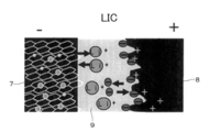
- FIG. 3 is a conceptual diagram showing an example thereof.
- the LIC is composed of, for example, an anode 7 made of Li-doped carbon, a cathode 8 made of activated carbon, and an electrolyte 9. Due to the electric field, Li ions and negative ions in the electrolytic solution 9 move to different electrode surfaces and adhere to the electrode surfaces. Thereby, it functions as a capacitor.
- the Li-added carbon of the anode 7 is obtained by adding Li ions between graphite layers, for example.
- FIG. 4 is a conceptual diagram illustrating an example of the operating principle of the LIC.
- FIG. 4B in the state where no electric field is applied to the electrode in the anode 7, for example, ion-bonded Li + PF 6 ⁇ floats in the electrolyte 9.
- Li ions are inserted between the graphite layers, and PF 6 ⁇ ions are attached to the surface of the activated carbon in the cathode 8.
- the electric double layer 100 is formed on the surface and charged.
- each ion moves from the electrode into the electrolytic solution, ionically bonds, and is discharged. This cycle is repeated.
- the anode 7 made of Li-added carbon functions as an energy source for insertion and extraction of lithium ions.
- the energy density can be increased to the level of the lithium ion battery. If Li ions are added to carbon in advance, the energy density can be further increased.
- the cathode 8 made of activated carbon functions as a power source.
- the product life can be extended like an electric double layer capacitor, and the output density can be increased.
- the energy density of the LIC is improved several times compared to the supercapacitor (EDLC), but is still inferior by several tens of times compared to the LIB.
- Carbon materials typified by activated carbon generally have (1) a large surface area (SSA) of the active surface, (2) a high electrical conductivity, and (3) a pore size accessible to electrolyte ions. It has the characteristic that many holes are uniformly distributed (nonpatent literature 5). Therefore, it has been studied to use various carbon materials as electrodes by taking advantage of such characteristics.
- SSA surface area
- CNT Carbon Nano tube
- SSA Small-patent Document 6
- graphene Graphene
- Graphene which is another carbon material, has a large number of pores with a uniform pore size that can be accessed by electrolyte ions, has a high electrical conductivity, and has a large SSA (26302 / g). .
- Non-Patent Documents 7 and 8 energy storage performance is improved (Non-Patent Documents 7 and 8), and reduced graphene formed by a chemical reduction method can also reduce manufacturing costs (Non-Patent Document 9).
- Non-Patent Document 10 problems such as restacking due to Van der Waals force and a decrease in electrical conductivity due to the influence of functional groups occur (Non-Patent Document 10).
- graphene its application to capacitors has also been studied from various viewpoints. For example, a supercapacitor including an electrode including an activated carbon layer and a graphene layer has been proposed (Patent Document 1).
- Non-Patent Document 2 Application to supercapacitors using graphene as a nanostructure material and an electrode material has also been studied (Patent Document 2, Non-Patent Document 11). Further, it has been reported that the CV curve of EDLCs is symmetrical (Non-Patent Document 12). Furthermore, characteristics due to the Li insertion / non-insertion process have been reported (Non-Patent Document 13). It has also been reported that when Urea-RGO was used as the cathode material, the specific capacity was 126 F / g and the energy density was 105 Wh / kg (Non-patent Document 14).
- the present invention further improves the advantages of the conventional supercapacitor (EDLC) and lithium ion capacitor (LIC), which have a high output density but a low energy density, and overcomes the disadvantages. It is another object of the present invention to provide a new Li ion supercapacitor that has a high output density, can be charged and discharged many times, and has a long product life.
- EDLC supercapacitor
- LIC lithium ion capacitor
- the present inventor has continued to study graphene-based electrodes that have been attracting attention in the past, and by using trial and error, graphene (graphene / CNT composite) added with a predetermined concentration of CNT was used.
- graphene graphene / CNT composite
- cathode cathode
- CNTs with high conductivity improve conductivity in the graphene thickness direction and function as spacers for preventing re-stacking of the graphene layer.
- a large number of pores having a diameter of 2 nm to 50 nm were uniformly formed in the cathode, and electrolyte ions could easily access the graphene active surface.
- a Li ion supercapacitor equipped with a graphene / CNT composite electrode, wherein both are made of graphene / CNT composite, and the CNT concentration in the graphene / CNT composite is 17 wt% or more and 33 wt% or less.
- a Li ion supercapacitor equipped with a graphene / CNT composite electrode wherein the graphene / CNT composite has a CNT concentration of 17 wt% or more and 20 wt% or less.
- the graphene and CNT are mixed to prepare a suspension, and then the suspension is filtered to form a film-like graphene / CNT composite; and the film-like graphene / CNT composite is used as one electrode, and a counter electrode made of graphite, Li-added graphite, or Li foil is placed on one side of the separator through a separator made of a porous polymer film or glass fiber.
- Li ion supercapacitor equipped with the graphene / CNT composite electrode of the present invention it is possible to provide a Li ion supercapacitor that has a high energy density and a high output density, can be charged and discharged many times, and has a long product life.
- the energy density and the output density are high, a large number of charge / discharge is possible, and the graphene / CNT composite cathode equipped with a long product life Li ion supercapacitors can be easily manufactured.
- FIG. 1 It is a conceptual diagram which shows an example of a lithium ion battery (lithium ion battery, Lithium-ion battery: LIB). It is a conceptual diagram which shows an example of an electrical double layer capacitor (Electrochemical double-layer capacitor: EDLC). It is a conceptual diagram which shows an example of a lithium ion capacitor (Lithium-ion supercapacitor: LIC). It is a conceptual diagram explaining an example of the operation principle of LIC.
- FIG. 2 is a diagram showing an example of a graphene / CNT composite electrode-equipped Li ion supercapacitor that is an embodiment of the present invention, and is a plan view of a coin cell having a graphene / CNT composite electrode equipped Li ion supercapacitor (a); A side view (b), a side development view (c), and a full cell (d). It is a conceptual diagram which shows an example of a graphene / CNT composite.
- FIG. 3 is a photograph (c) of a / CNT composite and a structural diagram (d) of a half-cell type Li ion supercapacitor. It is a CV curve of a coin cell (Example 1). It is a charge / discharge profile (Charge / discharge profile). It is a graph which shows the current density dependence of speed capability (Rate Capability). It is a graph which shows the EIS measurement result of a coin cell (Example 1).
- FIG. 3 is the initial charge / discharge profile of graphene / CNT composite at 0-3V at a current density of 50 mA / g.
- FIG. 5 is a view showing an example of a graphene / CNT composite electrode-equipped Li ion supercapacitor according to an embodiment of the present invention, and is a plan view of a coin cell having a graphene / CNT composite electrode equipped Li-ion supercapacitor.
- A side view
- c side development
- d full cell diagram
- the coin cell 30 has a coin cell case 18, a gasket 12, and a coin cell cap 11. Both have a circular shape in plan view, and the coin cell cap 11 can be fitted into the coin cell case 18 so as to seal the inside through the gasket 12.
- the gasket 12 has an annular shape, and a steel spacer 14, a current collector 20, an anode 15, a separator 16, a cathode 17, a current collector 21 from the spring 13 side by a spring 13 disposed in the ring.
- the members stacked in this order can be fixed by pressing against the inner bottom surface of the concave portion of the coin cell case 18.
- the graphene / CNT composite electrode-equipped Li ion supercapacitor 10 has a full cell 25 as a current collector 20, an anode 15, a separator 16, a cathode 17, and a current. They are stacked in the order of the collectors 21.
- graphene / CNT composite is used as the cathode 17, and the Li ion electrolyte solution 19 is filled between the anode 15 and the cathode 17.
- the graphene / CNT composite electrode-equipped Li ion supercapacitor 10 is configured.
- FIG. 6 is a conceptual diagram illustrating an example of a graphene / CNT composite.
- CNT: B is inserted between the graphene: A layers.
- each layer of graphene: A is regularly arranged so as to face each other at regular intervals, but is not limited thereto, and may be randomly arranged.
- CNT: B is regularly arrange
- the conductivity in the thickness direction of graphene is improved by disposing CNTs having high conductivity between the layers of graphene.
- the CNT functions as a spacer for preventing re-stacking of the graphene layer between the graphene layers, and the active surface of the graphene can be exposed.
- CNTs are arranged between graphene layers, a large number of holes having a diameter of 2 nm or more and 50 nm or less are formed between the graphene layers, thereby facilitating access of electrolyte ions to the active surface of the graphene. Because of these effects, the cathode characteristics are improved, and in the Li ion supercapacitor equipped with the graphene / CNT composite cathode, the energy density and the output density are increased, and the charge / discharge cycle is lengthened.
- the mass ratio of CNT to graphene in the graphene / CNT composite is 17 wt% or more and 33 wt% or less. More preferably, the content is 17 wt% or more and 20 wt% or less.
- the conductivity in the thickness direction cannot be sufficiently increased. Moreover, it partially restacks and the exposed area of the active surface of graphene becomes small. Further, the number of holes is not sufficient, and access of electrolyte ions to the active surface of graphene is not easy. Due to these factors, the energy density and the power density are reduced, and the charge / discharge cycle is also shortened. On the other hand, if it exceeds 33 wt%, the amount of CNT per unit volume is too large, and the exposed area of the active surface of graphene per unit volume becomes small, so that the energy density and output density are lowered, and the charge / discharge cycle is also shortened.
- the CNT is not particularly limited, and for example, a single-walled carbon nanotube (hereinafter abbreviated as SWCNT) can be mentioned as a suitable one. Double-walled carbon nanotubes (DWCNT) or even more multilayered carbon nanotubes may be used. More specifically, examples of the SWCNT include those having a diameter of 1 nm to 2 nm and a length of 5 mm to 30 mm. Commercial products can also be used without any treatment.
- SWCNT single-walled carbon nanotube
- DWCNT Double-walled carbon nanotubes
- examples of the SWCNT include those having a diameter of 1 nm to 2 nm and a length of 5 mm to 30 mm. Commercial products can also be used without any treatment.
- the anode 15 in FIGS. 5C and 5D it is preferable to use graphite or graphite to which Li ions are added.
- graphite Li ions can be sufficiently stored between layers.
- the Li concentration added to the graphite is appropriately set.
- the structure using the graphite which added graphite or Li ion as the anode 15 is called a full cell type Li ion supercapacitor.
- a configuration in which a Li foil is used as the anode 15 and the current collector 20 on the anode side is not used is referred to as a half-cell type Li ion supercapacitor and is usually used as a sample for evaluating cathode characteristics.
- Graphene / CNT can be used in EDLC as a cathode to replace activated carbon (AC) and in the LIC in this case because of the large surface area, mesoporous structure and large capacity resulting from good conductivity. Basically, it is necessary to pick up a good material for EDLC, which is the cathode of LIC.
- This material after pre-doping can be used as an anode in batteries or LICs to replace graphite due to the large capacity of Li, good rate capability and kinetic properties.
- a good battery anode with a very low lithiation voltage that is the anode of the LIC In this way, a dual-graphene / CNT LIC can be constructed and the same material can be used for both electrodes so that they can be easily matched.
- a porous polymer film, a glass fiber film, or the like can be used as the separator 16 illustrated in FIG. 5, a porous polymer film, a glass fiber film, or the like can be used.
- the porous polymer film may be of various types.
- a polypropylene (Polypropylene: PP) film can be mentioned as a suitable film.
- Li ion electrolytic solution 19 a solution in which Li ions are dispersed in an organic solvent can be used.
- a dispersion solution of an ion binding substance of Li ions and various anions can be used, and a preferable example is a Li: PF 6 dispersion solution.
- LiPF 6 is dissociated into Li ions and PF 6 ⁇ ions in an organic solvent and used for charging the electrodes.
- the LiPF 6 concentration is preferably 0.1 mol / L or more, and more preferably 0.5 mol / L or more. If it is less than 0.1 mol / L, the energy density becomes small.
- the organic solvent may be various types including conventionally known ones.
- suitable organic solvents include ethylene carbonate (abbreviated as EC) and diethyl carbonate (Diethyl Carbonate: DEC).
- EC ethylene carbonate
- DEC Diethyl Carbonate
- PC propylene carbonate
- DMC dimethyl carbonate
- a mixed organic solvent obtained by mixing EC and DEC at 1: 1 (v / v) can be used.
- the method for producing a graphene / CNT composite electrode-equipped Li ion supercapacitor of the present invention includes a reduced graphene synthesis step S1, a graphene / CNT composite preparation step S2, and a capacitor production step S3.
- reduced graphene synthesis step S1 reduced graphene is synthesized by synthesizing graphene oxide from graphite (graphite) by an improved Hammer method and then reducing it.
- the “Hummers method” is a method for producing graphene oxide (GO) using KMnO 4 and NaNO 3 in concentrated H 2 SO 4 [WS Hummers, Offeman, RE preparation of graphitic oxide. J Am Chem Soc 80 (1958)], where 'Modification' refers to a long oxidation time.
- the graphene synthesis method by this improved Hammer method is exemplified as the following procedure as a more specific process.
- Graphene / CNT composite production process S2 In this step, for example, the following procedure is possible. 1) First, single-walled carbon nanotubes (SWCNT) are prepared. 2) Weigh so that the CNT concentration in the total amount is 17 wt% or more and 33 wt% or less, mix graphene and SWCNT in an organic solvent, and then sonicate to prepare a suspension. For example, ethanol is used as the organic solvent. The CNT concentration in the total amount is more preferably 17 wt% or more and 20 wt% or less. In addition, the mass ratio of preparation becomes the same as a product.
- SWCNT single-walled carbon nanotubes
- Capacitor manufacturing process S3 The capacitor manufacturing process will be described with reference to FIG. 5. The order of the coin cell cap 11, the annular gasket 12, the spring 13, the steel spacer 14, the current collector 20, the Li ion supercapacitor 10, the current collector 21, and the coin cell case 18. Then, the coin cell cap 11 is fitted and fixed to the coin cell case 18 to produce the coin cell 30.
- the Li ion supercapacitor 10 includes, for example, an anode 15 made of Li ion-added graphite, a separator 16, and a cathode 17 made of a film-like graphene / CNT composite, and then stacked between the anode 15 and the cathode 17.
- An ionic electrolyte solution 19 is filled to prepare.
- the separator 16 for example, a porous polymer film or glass fiber can be used.
- the Li ion electrolyte 19 for example, a solution in which LiPF 6 is dispersed in an organic solvent is used.
- graphite or Li foil may be used. When Li foil is used as the anode 15, the steel spacer 20 can be omitted. As described above, a coin cell having a graphene / CNT composite electrode-equipped Li-ion supercapacitor is produced.
- the graphene / CNT composite electrode-equipped Li ion supercapacitor 10 of the present invention described as an example of the above embodiment, the following remarkable effects are realized.
- 1 having an anode 15, a cathode 17 spaced apart from the anode 15, and a Li ion electrolyte 19 filled between the anode 15 and the cathode 17, and either one of the cathode 17 or the anode or Both are composed of a graphene / CNT composite, and the CNT concentration in the graphene / CNT composite is 17 wt% or more and 33 wt% or less, so that the energy density and the output density are high, and a large number of charge and discharge are possible.
- We can provide Li-ion supercapacitors with long product life.
- the energy density and the output density are high and a large number of charge / discharge operations are possible by forming the porous body with pores having a pore diameter of 2 nm or more and 50 nm or less.
- Li ion electrolyte solution 19 By making the Li ion electrolyte solution 19 a LiPF 6 dispersion, the energy density and the output density are high, and a large number of charge / discharge operations are possible.
- the anode 15 is made of a carbon material, and the carbon material is made of graphite or Li ion-added graphite, so that the energy density and the output density are high and a large number of charge and discharge are possible.
- a separator 16 is disposed between the anode 15 and the cathode 17, and the separator 16 is a porous polymer membrane or a glass fiber, thereby providing a Li ion supercapacitor having a long product life. it can.
- the manufacturing process of the graphene / CNT composite electrode-equipped Li ion supercapacitor according to the present invention is performed by synthesizing the graphene oxide by the improved Hammer method as in the above embodiment, and then the graphene oxide. Reducing graphene and synthesizing reduced graphene, mixing graphene and CNT in an organic solvent so that the CNT concentration in the total amount is 17 wt% or more and 33 wt% or less, preparing a suspension, The suspension is filtered to prepare a film-like graphene / CNT composite, and the film-like graphene / CNT composite is used as one electrode (cathode 17).
- a long product lifetime graphene / CNT composite electrode equipped Li-ion supercapacitor can be easily manufactured.
- the graphene / CNT composite electrode-equipped Li-ion supercapacitor of the present invention and the manufacturing method thereof are not limited to the above-described embodiments, and various modifications are made within the scope of the technical idea of the present invention. can do. Examples of the present invention are shown below. However, the present invention is not limited to these examples.
- Example 1 (Graphene synthesis process: Synthesis of graphene oxide) Graphene oxide was synthesized from graphite (graphite) by the improved Hammer method as follows.
- the obtained black powder was washed several times with distilled water to remove excess hydrazine, and then dispersed again in water and sonicated to prepare a suspension.
- the suspension was centrifuged at 4000 rpm for 3 minutes to remove large particles, and the suspension was filtered under reduced pressure to recover the powder.
- the powder was vacuum dried to obtain the final graphene product.
- graphene was synthesized.
- graphene and SWCNT were weighed at a mass ratio of 4: 1, mixed in ethanol, and then sonicated to prepare a suspension.
- the suspension was vacuum filtered using a microporous filter to obtain a film.
- This film-like product was dried, and the dried film-like product was cut into a circular shape having a diameter of 15 mm in accordance with the cathode shape.
- a film-like graphene / CNT composite was prepared.
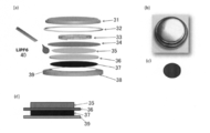
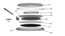
- FIG. 7 is an explanatory view of a half-cell type Li-ion supercapacitor.
- FIG. 7 is a perspective development view of a coin cell equipped with a half-cell type Li-ion supercapacitor (a), an optical photograph of the coin cell (b), and graphene / CNT in film form. It is the structure (d) of the photograph (c) of a composite_body
- FIG. 7A a coin cell cap 31, an annular gasket 32, a spring 33, a steel spacer 34, an anode 35, a separator 36, a cathode 37, a current collector (made of Al) 39, and a coin cell case 38 are stacked in this order.
- the coin cell was manufactured by filling the Li ion electrolyte solution 40 between the anode 35 and the cathode 32, and fitting and fixing the coin cell cap 31 to the coin cell case 38.
- FIG. 7 (b) shows an optical photograph from an oblique upper side of the coin cell cap.
- FIG. 7C shows a film-like graphene / CNT composite having a circular shape in plan view.
- Li ion electrolyte solution 40 a solution obtained by dissolving LiPF 6 at 1 mol / L in an organic solvent obtained by mixing ethylene carbonate (EC) and diethyl carbonate (DEC) at 1: 1 (v / v) was filled as the Li ion electrolyte solution 40.
- EC ethylene carbonate
- DEC diethyl carbonate
- the Li foil as the anode 35 is configured to directly contact the steel spacer without the current collector.
- the coin cell (Example 1) which stores a half cell type Li ion supercapacitor by the above was produced.
- CV measurement Using the above coin cell, CV (Cyclic Voltammetry) measurement was performed with different scanning speeds in the range of 5, 10, 20 mV / s and potentials in the range of 2-4 V.
- FIG. 8 is a CV curve of the measured coin cell.
- the CV curve was almost rectangular, and the capacitance (capacitance) was high as calculated from the area of the CV curve.
- the scanning speed was made higher, the deviation considered to be due to the Li insertion / non-insertion process increased.
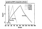
- FIG. 9 is a charge / discharge profile.
- C capacitance: capacitance
- C was calculated from this charge / discharge profile, and C was added to the following equation (1) to calculate the cell capacitance C cell .
- the energy density E was calculated by adding C cell , the minimum voltage V 1 and the maximum voltage V 2 to the following equation (2).
- FIG. 10 is a graph showing the current density dependence of the speed capability. As the current density was increased, the speed capability decreased, but it was maintained at about 70% at a current density of 1.2 A / g.
- EIS measurement EIS (Electrochemical impedance spectroscopy) measurement of the coin cell (Example 1) was performed. Impedance measurements were made without a DC bias of 0.005V sinusoidal signal in the frequency range of 10 kHz to 0.1 Hz.
- FIG. 11 is a graph showing the EIS measurement results of the coin cell (Example 1). For comparison, the result of only graphene (Comparative Example 1) is also shown.
- Example 1 A coin-shaped cell (Comparative Example 1) storing a half-cell Li-ion capacitor was prepared in the same manner as in Example 1 except that a film-like graphene was prepared by a known method and used as a cathode. First, CV measurement was performed with different scanning speeds in the range of 5, 10, 20 mV / s and potentials in the range of 2-4V.
- FIG. 12 is a CV curve of the coin cell (Comparative Example 1). Compared with the coin cell (Example 1), the current value was as small as about 1/3.
- FIG. 13 is a charge / discharge profile of a coin cell (Comparative Example 1).
- the capacitance was calculated from this charge / discharge profile. When the current density was 0.05 A / g, the capacitance was 194.6 F / g.
- Example 2 Coin cell for storing a half-cell type Li-ion capacitor in the same manner as in Example 1 except that graphene and SWCNT were weighed at a mass ratio of 3: 1 to prepare a graphene / CNT composite having a CNT concentration of 25 wt% (implemented) Example 2) was prepared.
- Example 3 A coin cell storing a half-cell type Li-ion capacitor in the same manner as in Example 1 except that graphene and SWCNT were weighed at a mass ratio of 2: 1 to prepare a graphene / CNT composite having a CNT concentration of 33 wt% (implemented) Example 3) was prepared.
- Example 4 Coin cell for storing a half-cell type Li ion capacitor in the same manner as in Example 1 except that graphene and SWCNT were weighed at a mass ratio of 5: 1 to prepare a graphene / CNT composite having a CNT concentration of 50 wt% (implementation) Example 4) was prepared.
- Example 2 A coin cell storing a half-cell type Li-ion capacitor in the same manner as in Example 1 except that graphene and SWCNT were weighed at a mass ratio of 1: 1 to prepare a graphene / CNT composite having a CNT concentration of 17 wt% (comparison) Example 2) was prepared.
- Example 5 A coin cell (Example 5) for storing a half-cell Li-ion capacitor was produced in the same manner as in Example 1 except that a glass fabric separator was used. First, CV measurement was performed with different scanning speeds in the range of 5, 10, 20 mV / s and potentials in the range of 2-4V. FIG. 14 is a CV curve of the coin cell (Example 5).
- FIG. 15 is a charge / discharge profile of a coin cell (Example 5).
- Example 5 A coin cell (Comparative Example 5) for storing the EDLC was manufactured in the same manner as in Example 1 except that AC was used as the anode and AC was used as the cathode.
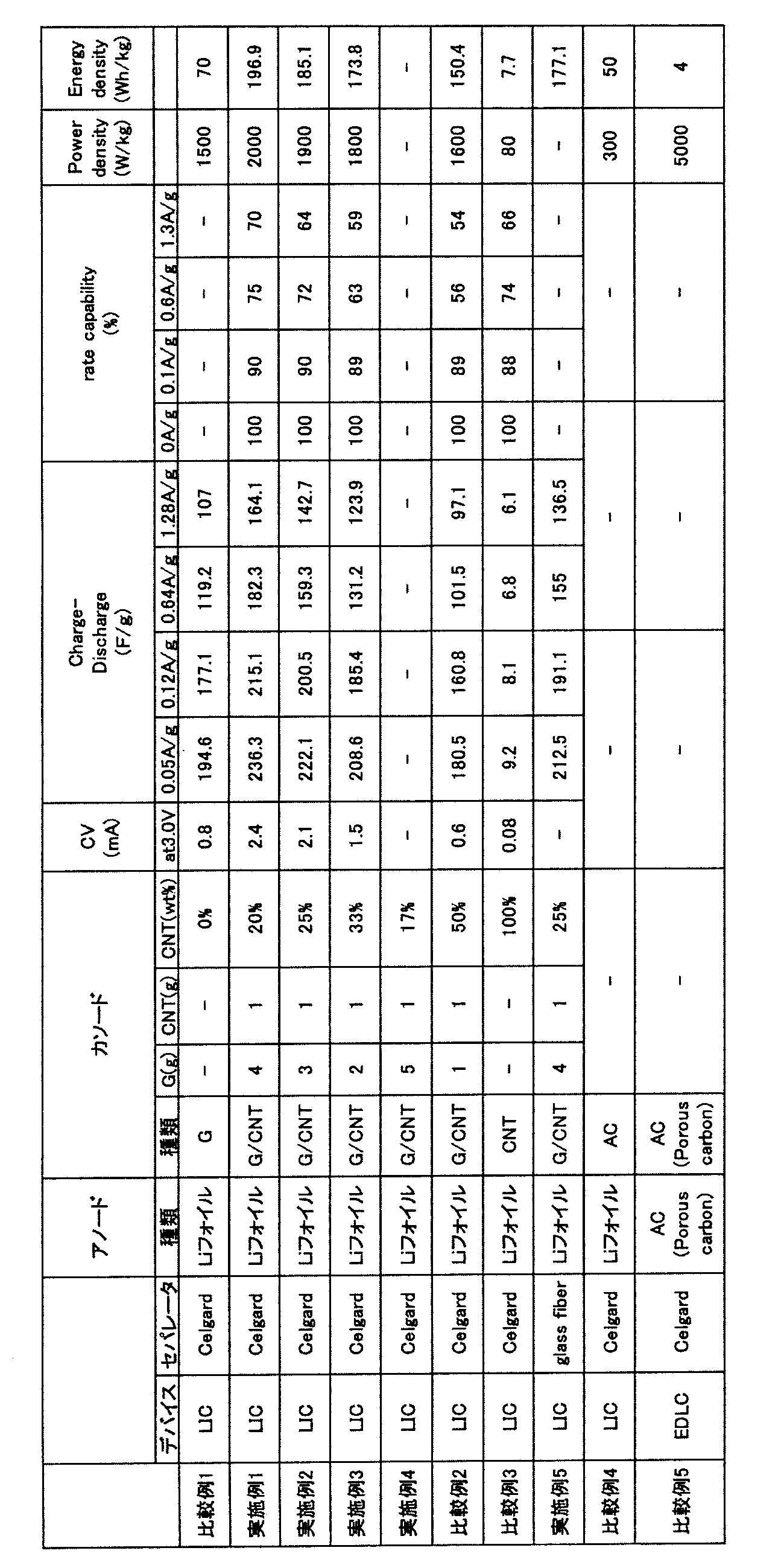
- Non-Patent Document 14 The results of coin cell (Example 1: graphene / CNT composite cathode), coin cell (Comparative Example 1, graphene / cathode), EDLC (Porous carbon), and coin cell (AC) are shown (Non-Patent Document 14).
- the power density and energy density of the coin cell (Example 1: graphene / CNT composite cathode) showed the best performance compared to other data. Specifically, the power density was 89 W / kg and the energy density was 177 Wh / kg.
- Table 1 shows the types of devices produced, separator types, cathode types and composition ratios, CV characteristics, charge / discharge characteristics, coulomb efficiency, power density, and energy density.
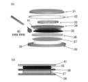
- FIG. 17 is an explanatory view of a full-cell Li-ion supercapacitor.
- FIG. 17 is a perspective development view of a coin cell provided with the full-cell Li-ion supercapacitor manufactured in the example, and the structure of the full-cell Li-ion supercapacitor.
- FIG. 17 is a perspective development view of a coin cell provided with the full-cell Li-ion supercapacitor manufactured in the example, and the structure of the full-cell Li-ion supercapacitor.
- FIG. 18 is a CV curve of a coin cell (Example 6).
- FIG. 19 is a discharge profile of a coin cell (Example 6).
- FIG. 20 is a graph showing the pore size (pore size) and surface area distribution (surface area distribution) of CNT / graphene (abbreviated as reduced graphene oxide: rGO).
- the ratios of Micropore (less than 2 nm), Mesopore (2 nm or more and 50 nm or less), and Macropore (greater than 50 nm) are shown in Table 2 below.
- BET SSA is the BET specific surface area.
- CRGO is an abbreviation for Chemical reduced GO and has the same meaning as rGO. The case of only SWNT and only rGO is also shown.
- Example 7 (Creation of graphene / CNT composite) A film-like graphene / CNT composite was produced in the same manner as in Example 1.
- Example 7 A half cell type coin cell (Example 7) was produced in the same manner as in Example 1.
- This coin cell includes a half cell type Li ion supercapacitor.
- a film-like graphene / CNT composite is used as the cathode 37 in FIG. 7
- lithium foil is used as the anode 35
- ethylene carbonate (EC) and diethyl carbonate (DEC) are 1
- a solution obtained by dissolving LiPF 6 at 1 mol / L in an organic solvent mixed at 1 (v / v) was filled as a Li ion electrolyte solution 40.
- CV measurement First, using a coin cell (Example 7), CV (Cyclic Voltammetry) measurement was performed at potentials ranging from 0 to 3 V at different scanning speeds ranging from 5, 10, and 20 mV / s. This is an anode characteristic.
- FIG. 21 is a CV curve of the coin cell (Example 7).
- the CV curve has a substantially trapezoidal shape, and the capacitance (capacitance) was calculated from the area of the CV curve. The area increased when the scanning speed was increased. A redox peak was obtained around 0V. It is assumed that intercalation has occurred here.
- CNT serves as a spacer to form a porous structure with electrochemically active nanopores as Li intercalation sites and to separate the graphene layer.
- Li ion can be easily and sufficiently intercalated on the active surface of graphene.
- a graphite intercalation compound having LiC 3 as a main product is formed.
- FIG. 23 is a graph of the relationship between capacity and current for anode capability comparison of rate capability.
- the graphene / CNT composite used for the anode is denoted as Co-reduced graphene.
- Co-reduced graphene the results of using hard carbon and graphite as the anode are also shown.
- C (Imax) is the capacity at the maximum current value
- C (Imin) is the capacity at the minimum current value.
- C (discharge) is the minimum capacity of the discharge profile
- C (charge) is the maximum capacity of the charge profile.
- FIG. 24 is a bar graph showing the relationship between specific capacity, rate capability, and irreversible capacity loss. It can be seen from FIG. 24 that the anode using the graphene / CNT composite exhibits better rate capability than the other two types of carbon: hard carbon and graphite. This indicates that Li is intercalated into graphene / CNT sufficiently efficiently or even deintercalated from graphene / CNT, even at higher currents. Such performance is a guarantee of good rate capability and stability of LIC with graphene / CNT as anode.
- FIG. 25 is an explanatory diagram of the apparatus, and is an explanatory diagram of the EC method (a) and the ESC method (b).
- a current collector 51, graphene 52, a separator 53, and lithium 54 are stacked, and a Li ion electrolyte 55 is added.
- FIG. 26 is a discharge profile at a current density of 0.05 A / g in the EC method.
- a lithiation process was seen. It is a process for forming a compound composed of lithium and an anode element by doping a lithium into an anode material and an anode material. For example, if the carbonized material is doped with lithium, LiC x is formed.
- FIG. 27 is an explanatory diagram of a full-cell Li-ion supercapacitor.
- FIG. 27 is a perspective development view of a coin cell provided with the full-cell Li-ion supercapacitor produced in this example, and FIG. It is structural drawing (b).
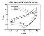
- FIG. 28 is a CV curve of the coin cell (Example 8).
- the CV curve has a substantially triangular shape, and the capacitance (capacitance) was calculated from the area of the CV curve. The area increased when the scanning speed was increased.
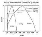
- FIG. 29 is a charge / discharge profile (Charge / discharge profile) of a coin cell (Example 8).
- the capacities at current densities of 0.05 A / g, 0.12 A / g, and 1.28 A / g were 40.6 F / g, 70.7 F / g, and 85.2 F / g, respectively.
- Table 3 is a characteristic comparison of Li ion supercapacitors.
- MCMB is an abbreviation for mesocarbon microbead.
- H 2 O 2 modidied MCMB is a MCMB was treated with H 2 O 2.
- LTO is an abbreviation for lithium titanium oxide.
- Packaged cell energy density is the energy density of the entire cell.
- Example 9 Capacitor manufacturing (Production of half-cell Li-ion supercapacitor)
- a coin cell (Example 9) was produced in the same manner as Example 7 having the configuration shown in FIG.
- This coin cell includes a half cell type Li ion supercapacitor.
- a film-like graphene / CNT composite (graphene / CNT) is used as the cathode 37, and a lithium foil is used as the anode 35 which is a counter electrode.
- FIG. 30 shows the anode performance of the first cycle.
- the first discharge gave a very large capacity of 2515 mAh / g, and a reversible capacity of 815 mAh / g was obtained with the first charge.
- Graphene / CNT prepared by chemical co-reduction method not only shows better performance than previously reported graphene / CNT and graphene / C60 [Yoo et al, Nano Letters, 8 (2008) 2277] Even graphene ⁇ ⁇ [H. Kim et al, Carbon, 2011, 49, 326] combined with tin oxide, which shows high properties for Li accommodation, can be compared.
- Such a large Li capacity meets the strict requirements of LIC anodes that provide sufficient Li.
- Example 10 (Production of full-cell Li-ion supercapacitor)
- Example 10 a full cell type Li ion supercapacitor similar to Example 6 having the configuration shown in FIG. 17 was produced.
- the configuration is the same as in Example 6 except that a graphene / CNT composite is used as the cathode 37 and a graphene / CNT composite pre-doped with Li ions is used as the anode 35. That is, the configuration is the same as that of the eighth embodiment.
- FIG. 31 shows the electrochemical properties of dual-graphene / CNT LIC (full cell LIC).
- FIG. 31A shows a charge / discharge profile close to a rectangular shape representing supercapacitor characteristics.
- FIG. 31B shows a charge / discharge profile for calculating the capacity when the current density is changed. At 50 mA / g, the capacity can reach 274 F / g. The rate capability is shown in Fig. 31 (c).
- the specific capacity of the dual-graphene LIC reaches 237 F / g, 229 F / g, and 224 F / g, respectively, and this LIC has a large rate capability. Is shown.
- the capacitance at 2-4 V and the current density of 60 mA / g was 274 F / g, and the energy density was 114 Wh / kg.
- the Li-ion supercapacitor of the present invention relates to a Li-ion supercapacitor equipped with a graphene / CNT composite electrode having a CNT concentration of 17 wt% or more and 33 wt% or less. It has a long product life and can be used in the capacitor industry, the battery industry, and the like.
Landscapes
- Engineering & Computer Science (AREA)
- Power Engineering (AREA)
- Chemical & Material Sciences (AREA)
- Microelectronics & Electronic Packaging (AREA)
- Chemical Kinetics & Catalysis (AREA)
- Electrochemistry (AREA)
- Materials Engineering (AREA)
- Crystallography & Structural Chemistry (AREA)
- Nanotechnology (AREA)
- Manufacturing & Machinery (AREA)
- Electric Double-Layer Capacitors Or The Like (AREA)
Abstract
Description
LICは、例えば、Li添加カーボン(Li-doped carbon)からなるアノード7と、活性炭からなるカソード8と、電解液9とから構成されている。電界により、電解液9中のLiイオンとマイナスイオンがそれぞれ異なる電極表面に移動して、電極表面に付着される。これにより、キャパシターとして機能する。アノード7のLi添加カーボンは、例えば、グラファイトの層間にLiイオンを添加したものである。
図4(b)に示すように、アノード7における電極に電界が印加されていない状態では、電解液9中に、例えばイオン結合したLi+PF6 -が浮遊している。次に、電極に電界を印加することにより、図4(a)に示すように、グラファイトの層間にはLiイオンが挿入され、カソード8における活性炭の表面にはPF6 -イオンが付着され、活性炭表面に電気二重層100が形成されて、チャージされる。電極への電界印加をやめると、それぞれのイオンは電極から電解液中に移動し、イオン結合して、ディスチャージする。このサイクルが繰り返される。
また、活性炭からなるカソード8は電源として機能する。これにより、電気二重層キャパシターのように製品寿命を長くでき、出力密度を高めることができる。
しかし、LICのエネルギー密度は、スーパーキャパシター(EDLC)に比べると数倍程度向上するが、LIBに比べると依然として数十倍程度劣る。
そこで、このような特性を生かして、様々な炭素材料を電極とすることが検討されている。
一方、別の炭素材料であるグラフェン(Graphene)は、電解質イオンがアクセス可能な孔径の多数の孔が均一分布されており、電気伝導度が高く、大きなSSA(26302/g)を有している。このようなグラフェンを用いることにより、エネルギー・ストレージ性能が向上すること(非特許文献7、8)や、化学還元法により形成した還元グラフェンは、製造コストも低減できること(非特許文献9)が報告されている。しかし、ファンデルワールス(Van der waals)力により再スタッキングや、官能基の影響により電気伝導度が低くなるという問題が発生すると指摘されている(非特許文献10)。
グラフェンについては、キャパシターへの応用についても様々な観点より検討されている。例えば、活性炭層とグラフェン層とを含む電極を具備したスーパーキャパシターが提案されている(特許文献1)。グラフェンをナノ構造材料として電極材料としたスーパーキャパシターへ応用も検討されている(特許文献2、非特許文献11)。また、EDLCsのCVカーブが対称形であることが報告されている(非特許文献12)。
さらにまた、Li挿入/非挿入プロセスによる特性が報告されている(非特許文献13)。カソード材料としてUrea-RGOを用いた場合には、比容量126F/g、エネルギー密度105Wh/kgであったことも報告されている(非特許文献14)。
また、更に試行錯誤を続けて、グラフェン/CNT複合体を用いたアノード(陽極)を装備させる場合においてもエネルギー密度を高めるとともに、充放電サイクル数を増やすことができた。
更に、カソード及びアノードの双方にグラフェン/CNT複合体を用いたLiイオン・スーパーキャパシターにより、エネルギー密度を高めるとともに、充放電サイクル数を増やすことができることを見出して、本発明を完成した。
以上の経緯をもって完成された本発明は、以下の特徴を有している。
(3)前記グラフェン/CNT複合物が多孔質体であることを特徴とするグラフェン/CNT複合体電極装備Liイオン・スーパーキャパシター。
(4)前記多孔質体に2nm以上50nm以下の孔径の孔が形成されていることを特徴とするグラフェン/CNT複合体電極装備Liイオン・スーパーキャパシター。
(6)前記アノードがグラファイト又はLiイオン添加グラファイトであることを特徴とするグラフェン/CNT複合体電極装備Liイオン・スーパーキャパシター。
(7)前記アノードと前記カソードとの間にセパレーターが配置されており、前記セパレーターが、多孔質高分子膜又はグラスファイバーであることを特徴とするグラフェン/CNT複合体電極装備Liイオン・スーパーキャパシター。
まず、本発明のグラフェン/CNT複合体電極装備Liイオン・スーパーキャパシターの実施形態の一例について説明する。
図5は、本発明の実施形態であるグラフェン/CNT複合体電極装備Liイオン・スーパーキャパシターの一例を示す図であって、グラフェン/CNT複合体電極装備Liイオン・スーパーキャパシターを有するコインセルの平面図(a)、側面図(b)、側面展開図(c)、フルセル図(d)である。
図6に示すように、グラフェン/CNT複合体では、グラフェン:Aの層間にCNT:Bが挿入されている。図6の例示では、グラフェン:Aの各層は等間隔に、かつ、対面するように規則的に配置されているが、これに限られるものではなく、ランダムに配置されていてもよい。また、CNT:Bは等間隔に、かつ、平行に規則的に配置されているが、これに限られるものではなく、ランダムに配置されていてもよい。
これらの効果により、カソード特性が向上されるので、グラフェン/CNT複合体カソードを装備したLiイオン・スーパーキャパシターでは、エネルギー密度及び出力密度が高められ、充放電サイクルも長くなる。
逆に、33wt%超では、単位体積当たりのCNT量が多すぎ、単位体積当たりのグラフェンの活性面の露出面積が小さくなるので、エネルギー密度及び出力密度が低下し、充放電サイクルも短くなる。
SWCNTとしては、より具体的には、好適なものとして直径1nm以上2nm以下、長さ5mm以上30mm以下のものを挙げることができる。市販品を、何の処理を行うことなく、用いることもできる。
なお、アノード15としてグラファイト又はLiイオン添加したグラファイトを用いる構成はフルセル型Liイオン・スーパーキャパシターと呼称する。また、アノード15としてLiフォイルを用い、アノード側のカレントコレクター20を用いない構成はハーフセル型Liイオン・スーパーキャパシターと呼称し、通常、カソード特性の評価サンプルとして利用する。
グラフェン/CNTは、大きな表面積、メソポーラス構造及び良好な導電性から生じる大きな容量のため、活性炭素(AC)に置き換わるカソードとしてEDLCにおいて、また本ケースのLICにおいて使用することができる。基本的に、LICのカソードであるEDLCのための良好な材料をピックアップする必要がある。
プレ・ドーピング後のこの材料は、Liの大きな容量、良好なレート・ケイパビリティ(rate capability)及びキネティクス特性のため、グラファイトと置き換わる電池又はLICにおけるアノードとして使用することができる。基本的に、LICのアノードである非常に小さいリチウム化電圧を持つ良好な電池のアノードを見出す必要がある。
このように、デュアル-グラフェン/CNT LICを構築することができ、両電極に同じ材料を用いることができるので、それらを容易にマッチさせることができる。
次に、本発明の実施形態として、グラフェン/CNT複合体電極装備Liイオン・スーパーキャパシターの製造方法の一例を説明する。
本発明のグラフェン/CNT複合体電極装備Liイオン・スーパーキャパシターの製造方法は、還元グラフェン合成工程S1と、グラフェン/CNT複合体作成工程S2と、キャパシター製造工程S3とを含む。
この工程では、改良型ハマー法により、黒鉛(グラファイト)からグラフェン酸化物を合成してから、これを還元して、還元グラフェンを合成する。ここで、「ハマー法(Hummers method)とは、濃縮H2SO4中のKMnO4及びNaNO3を用い酸化グラフェン(GO)を製造する方法である [W. S. Hummers, Offeman, R. E. preparation of graphitic oxide. J Am Chem Soc 80 (1958)]。ここで、'Modification'とは、長い酸化時間をいう。
この改良型ハマー法によるグラフェンの合成法は、より具体的な工程としては例えば以下の手順として例示される。
1)すなわちまず、グラファイトとNaNO3をフラスコ内で混合し、H2SO4を加えてから、アイスバスで懸濁液をかき混ぜる。
2)ゆっくりと懸濁液に過マンガン酸カリウムを加え、混合物をフラスコ内で2時間かき混ぜる。
3)蒸留水を加えて、かき混ぜる。
4)懸濁液を超音波処理する。
5)遠心分離する。
6)真空乾燥する。
以上により、グラフェン酸化物(Graphene oxide:GOと略記する。)を合成する。
8)ホットプレート上で、懸濁液を徐々に加熱する。例えば、加熱温度は100℃とする。
9)ヒドラジンハイドレイト(ヒドラジン水和物)を加え、懸濁液を前記加熱温度近傍の温度で所定時間保持する。例えば、98℃、24時間の条件とする。
10)懸濁液を濾過する。
11)黒色粉末を数回蒸留水で洗浄し、過剰なヒドラジンを取り除いた後、再び、水中に分散させ、超音波処理して、懸濁液を調製する。
12)懸濁液を遠心分離する。例えば、4000rpm、3分の条件とする。
13)懸濁液を減圧濾過する。
14)粉末を真空乾燥処理する。
以上により、グラフェンを合成する。
この工程では、例えば以下の手順が可能とされる。
1)まず、単層カーボンナノチューブ(SWCNT)を用意する。
2)合計量におけるCNT濃度が17wt%以上33wt%以下となるように秤量して、有機溶媒中でグラフェンとSWCNTを混合してから、超音波処理して、懸濁液を調製する。有機溶媒としては、例えば、エタノールを用いる。なお、合計量におけるCNT濃度は17wt%以上20wt%以下とすることがより好ましい。なお、仕込みの質量比が、製造物と同じとなる。
4)フィルム状物を乾燥する。
5)乾燥したフィルム状物を、カソード形状に合わせて直径15mmの円形状に切り取る。
以上の工程により、フィルム状のグラフェン/CNT複合体を作成する。
図5を参照例として、キャパシター製造工程を説明すると、コインセルキャップ11、環状のガスケット12、スプリング13、スチールスペーサー14、カレントコレクター20、Liイオン・スーパーキャパシター10、カレントコレクター21、コインセルケース18の順序で重ねて配置してから、コインセルキャップ11をコインセルケース18に嵌合固定して、コインセル30を作製する。
以上により、グラフェン/CNT複合体電極装備Liイオン・スーパーキャパシターを有するコインセルを作製する。
1;アノード15と、アノード15に離間して配置されたカソード17と、アノード15とカソード17の間に充填されたLiイオン電解液19と、を有し、カソード17又はアノードのいずれか一方又は双方がグラフェン/CNT複合体からなり、前記グラフェン/CNT複合体におけるCNT濃度が17wt%以上33wt%以下である構成とすることで、エネルギー密度及び出力密度が高く、充放電を数多く可能で、長製品寿命のLiイオン・スーパーキャパシターを提供できる。
(グラフェン合成工程:グラフェン酸化物の合成)
以下のようにして、改良型ハマー法により、黒鉛(グラファイト)からグラフェン酸化物を合成した。
次に、蒸留水90mlを加えて、かき混ぜて、黄色の懸濁液とした。この黄色の懸濁液を、超音波処理した。これにより、グラファイト酸化物粒子からグラフェン酸化物片をはがし取った。
以上により、グラフェン酸化物を合成した。
100mgのグラフェン酸化物の粒子を蒸留水30mlに分散し、30分間、超音波処理して、懸濁液を調製した。ホットプレート上で、この懸濁液を徐々に加熱し、100℃とした。
次に、ヒドラジンハイドレイト(ヒドラジン水和物)3mlを加えてから、懸濁液を24時間98℃に保持した。その後、懸濁液を濾過して、黒色粉末を回収した。
粉末を真空乾燥処理して、最終グラフェン生成物を得た。
以上により、グラフェンを合成した。
単層カーボンナノチューブ(SWCNT)は、市販品(Cheap Tube.Inc.,>90%、amorphous carbon content 3wt%、length:5-30mm、diameter:1-2nm)を用意した。
このカーボンナノチューブは何の処理も行うことなく用いた。
このフィルム状物を乾燥し、乾燥した後のフィルム状物を、カソード形状に合わせて直径15mmの円形状に切り取った。
以上により、フィルム状のグラフェン/CNT複合体を作成した。
(ハーフセル型Liイオン・スーパーキャパシターの作製)
図7は、ハーフセル型Liイオン・スーパーキャパシターの説明図であり、ハーフセル型Liイオン・スーパーキャパシターを備えたコインセルの斜視展開図(a)、コインセルの光学写真(b)、フィルム状のグラフェン/CNT複合体の写真(c)、ハーフセル型Liイオン・スーパーキャパシターの構造図(d)である。
図7(b)に、コインセルキャップ斜め上方からの光学写真を示す。
図7(c)には、平面視円状のフィルム状のグラフェン/CNT複合体を示す。
エチレンカーボネイト(EC)と、ジエチルカーボネイト(DEC)を1:1(v/v)で混合した有機溶媒に、LiPF6を1mol/Lで溶解した溶液をLiイオン電解液40として充填した。
以上により、ハーフセル型Liイオン・スーパーキャパシターを格納するコインセル(実施例1)を作製した。
上記のコインセルを用いて、5、10、20mV/sの範囲の異なるスキャン速度で、2~4Vの範囲のポテンシャルで、CV(Cyclic Voltammetry)測定を行った。
CVカーブはほとんど長方形状であり、そのCV曲線の面積から算出して、キャパシタンス(静電容量)は高かった。スキャン速度をより速くした場合に、Li挿入/非挿入プロセスによると考えられるずれが大きくなった。
次に、コインセルを用いて、Liイオン・スーパーキャパシターの電流密度0.05A/g、0.12A/g、0.64A/g、1.28A/gにおけるチャージ/ディスチャージ(Charge/Discharge)測定を行った。


次に、コインセル(実施例1)のEIS(Electrochemical impedance spectroscopy)測定を行った。
インピーダンス測定は、10kHz~0.1Hzの周波数範囲で0.005Vの正弦関数シグナルのDCバイアスなしで行った。
図11は、コインセル(実施例1)のEIS測定結果を示すグラフである。比較のために、グラフェンのみの結果(比較例1)も示している。
公知の方法によりフィルム状のグラフェンを作成し、これをカソードとして用いた他は実施例1と同様にして、ハーフセル型Liイオン・キャパシターを格納するコインセル(比較例1)を作製した。
まず、5、10、20mV/sの範囲の異なるスキャン速度で、2~4Vの範囲のポテンシャルで、CV測定を行った。図12は、コインセル(比較例1)のCV曲線である。コインセル(実施例1)に比べて電流値が1/3程度と小さかった。
このチャージ/ディスチャージ プロファイルからキャパシタンス(静電容量)を算出した。電流密度0.05A/gのとき、静電容量は194.6F/gであった。
グラフェンとSWCNTを質量比3:1で秤量して、CNT濃度が25wt%のグラフェン/CNT複合体を作成した他は実施例1と同様にして、ハーフセル型Liイオン・キャパシターを格納するコインセル(実施例2)を作製した。
グラフェンとSWCNTを質量比2:1で秤量して、CNT濃度が33wt%のグラフェン/CNT複合体を作成した他は実施例1と同様にして、ハーフセル型Liイオン・キャパシターを格納するコインセル(実施例3)を作製した。
グラフェンとSWCNTを質量比5:1で秤量して、CNT濃度が50wt%のグラフェン/CNT複合体を作成した他は実施例1と同様にして、ハーフセル型Liイオン・キャパシターを格納するコインセル(実施例4)を作製した。
グラフェンとSWCNTを質量比1:1で秤量して、CNT濃度が17wt%のグラフェン/CNT複合体を作成した他は実施例1と同様にして、ハーフセル型Liイオン・キャパシターを格納するコインセル(比較例2)を作製した。
フィルム状のSWCNTをカソードとして用いた他は実施例1と同様にして、ハーフセル型Liイオン・キャパシターを格納するコインセル(比較例3)を作製した。
ガラスファブリック・セパレーターを用いた他は実施例1と同様にして、ハーフセル型Liイオン・キャパシターを格納するコインセル(実施例5)を作製した。
まず、5、10、20mV/sの範囲の異なるスキャン速度で、2~4Vの範囲のポテンシャルで、CV測定を行った。
図14は、コインセル(実施例5)のCV曲線である。
図15は、コインセル(実施例5)のチャージ/ディスチャージ プロファイルである。
ACをカソードとして用いた他は実施例1と同様にして、ハーフセル型Liイオン・キャパシターを格納するコインセル(比較例4)を作製した。
アノードとしてAC、カソードとしてACを用いた他は実施例1と同様にして、EDLCを格納するコインセル(比較例5)を作製した。
コインセル(実施例1:グラフェン/CNT複合体カソード)、コインセル(比較例1、グラフェン・カソード)、EDLC(Porous carbon)、コインセル(AC)の結果を示している(非特許文献14)。
(フルセル型Liイオン・スーパーキャパシターの作製)
図17は、フルセル型Liイオン・スーパーキャパシターの説明図であり、実施例で作製したフルセル型Liイオン・スーパーキャパシターを備えたコインセルの斜視展開図(a)、フルセル型Liイオン・スーパーキャパシターの構造図(b)である。
図18は、コインセル(実施例6)のCV曲線である。
図19は、コインセル(実施例6)のディスチャージ プロファイル(discharge profile)である。
図20は、CNT/graphene(reduced Graphene oxide:rGOと略する。)の孔サイズ(Pore size)と表面積分布(surface area distribution)を示すグラフである。Micropore(2nm未満)、Mesopore(2nm以上50nm以下)、Macropore(50nm超)の割合を下記の表2に示した。BET SSAはBET比表面積である。CRGOはChemical reduced GOの略で、rGOと同じ意味である。SWNTのみ、rGOのみの場合を合わせて示している。

(グラフェン/CNT複合体の作成)
実施例1と同様にして、フィルム状のグラフェン/CNT複合体を作成した。
(ハーフセル型Liイオン・スーパーキャパシターの作製)
実施例1の構成と同様にして、ハーフセル型のコインセル(実施例7)を作製した。
このコインセルはハーフセル型Liイオン・スーパーキャパシターを備えている。
このハーフセル型Liイオン・スーパーキャパシターでは、図7におけるカソード37として、フィルム状のグラフェン/CNT複合体を用い、アノード35としてリチウム・フォイルを用い、エチレンカーボネイト(EC)とジエチルカーボネイト(DEC)を1:1(v/v)で混合した有機溶媒に、LiPF6を1mol/Lで溶解した溶液をLiイオン電解液40として充填した。
まず、コインセル(実施例7)を用いて、5、10、20mV/sの範囲の異なるスキャン速度で、0~3Vの範囲のポテンシャルで、CV(Cyclic Voltammetry)測定を行った。これはアノード特性となる。
CVカーブは略台形形状であり、そのCV曲線の面積からキャパシタンス(静電容量)を算出した。スキャン速度をより速くした場合に、面積は大きくなった。
0V付近にレドックスピークが得られた。ここでインターカレーションが生じたと考える。
次に、コインセル(実施例7)を用いて、Liイオン・スーパーキャパシターの電流密度0.05A/gにおけるチャージ/ディスチャージ(Charge/Discharge)測定を行った。1stから6thまでチャージ/ディスチャージを繰り返した。
Crev=437mAh/gとなり、Cirr=63mAh/gとなった。不可逆な容量ロスは小さく、クーロン効率が良かった。
ディスチャージ プロファイルから、0.5V以上3V以下の領域は電圧ドロップが早いので、電極にLiイオンが吸着するファラデープロセスが支配的であるのに対し、0V以上0.5V以下の領域では、電極のグラフェン/CNT複合体へのLiイオンのインターカレーション/デインターカレーションが支配的となることが推察された。
次に、図22のデータ及び電流値を変えたときの同様の測定によるデータに基づいて、レート・ケイパビリティ(rate capability)のアノード材料比較に係る、容量と電流の関係のグラフを作成した。
図23は、レート・ケイパビリティ(rate capability)のアノード材料比較に係る、容量と電流の関係のグラフである。アノードに用いたグラフェン/CNT複合体をCo-reduced grapheneと表記している。比較のために、hard carbon及びgraphiteをアノードに用いた結果も示している。


この図24から、グラフェン/CNT複合体を用いたアノードが、他の2つのタイプのカーボン:ハードカーボンとグラファイトよりより良好なレート・ケイパビリティ(rate capability)を示すことがわかる。これは、より大きな電流でさえLiを十分効率的にグラフェン/CNTにインターカレーションさせるか、またはグラフェン/CNTからデ・インターカレーションさせるこれを示している。このような性能はアノードとしてグラフェン/CNTを備えたLICの良好なレート・ケイパビリティ(rate capability)と安定性の保証である。
電気化学(EC)法又は外部ショートサーキット(External short circuit:ESC)法を用いて、1mol LiPF6(EC/DEC(v:v=1:1))の電解液中で、リチウムイオンソースとしてリチウム金属電極を備えた構成で、グラファイト・アノードに対して、Liイオンのプリドーピングを行った。
図25は、装置説明図であり、EC法(a)、ESC法(b)の説明図である。装置の構成においては、カレントコレクター51、グラフェン52、セパレーター53、リチウム54が積層されLiイオン電解液55が加えられている。
EC法では、リチウム54とカレントコレクター51を配線により接触させただけである。ESC法では、配線を電源に接続している。
図26は、EC法での電流密度0.05A/gにおけるDischargeプロファイルである。リチエーション・プロセス(Lithiation process)が見られた。リチエーション・プロセスとアノード材料にリチウムをドープして、リチウムとアノード元素とからなる化合物を形成するプロセスである。例えば、炭化材料にリチウムをドープすると、LiCxが形成される。
(フルセル型Liイオン・スーパーキャパシターの作製)
図17の実施例6と同様のフルセル型Liイオン・スーパーキャパシターを作製した。
図27は、フルセル型Liイオン・スーパーキャパシターの説明図であり、本実施例で作製したフルセル型Liイオン・スーパーキャパシターを備えたコインセルの斜視展開図(a)、フルセル型Liイオン・スーパーキャパシターの構造図(b)である。
5、10、20mV/sの各掃引速度で、このコインセルのCV測定を行った。
図28は、コインセル(実施例8)のCV曲線である。
CVカーブは略三角形状であり、そのCV曲線の面積からキャパシタンス(静電容量)を算出した。スキャン速度をより速くした場合に、面積は大きくなった。
次に、コインセルを用いて、2~4Vで、Liイオン・スーパーキャパシターのチャージ/ディスチャージ(Charge/Discharge)測定を行った。
表3は、Liイオン・スーパーキャパシターの特性比較である。ここで、MCMBはメゾカーボン マイクロビード(mesocarbon microbead)の略である。また、H2O2 modidied MCMBは、H2O2で処理したMCMBである。LTOは、リチウム チタニウム オキサイド(lithium titanium oxide)の略である。
また、Packaged cell energy densityは、セル全体のエネルギー密度である。
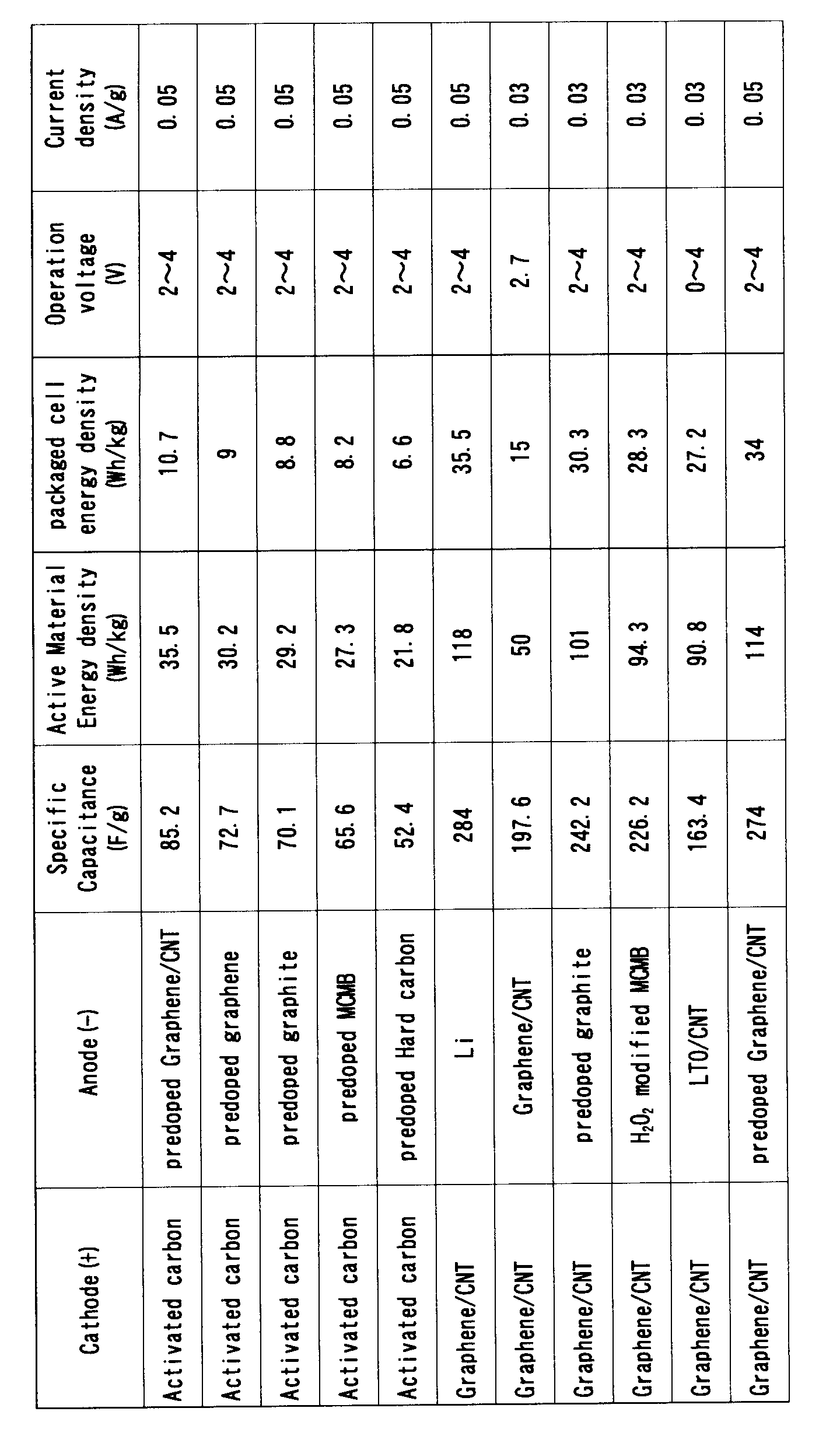
(キャパシター製造)
(ハーフセル型Liイオン・スーパーキャパシターの作製)
図7の構成の実施例7と同様にして、コインセル(実施例9)を作製した。
このコインセルはハーフセル型Liイオン・スーパーキャパシターを備えている。
このハーフセル型Liイオン・スーパーキャパシターでは、カソード37として、フィルム状のグラフェン/CNT複合体(graphene/CNT)を用い、対電極(counter electrode)であるアノード35としてリチウム・フォイル(Lithium foil)を用い、エチレンカーボネイト(EC)とジエチルカーボネイト(DEC)を1:1(v/v)で混合した有機溶媒に、LiPF6を1mol/Lで溶解した溶液をLiイオン電解液40として充填した。
(フルセル型Liイオン・スーパーキャパシターの作製)
次に、図17の構成の実施例6と同様のフルセル型Liイオン・スーパーキャパシターを作製した。
カソード37としグラフェン/CNT複合体を用い、アノード35としてLiイオンをプリドープしたグラフェン/CNT複合体を用いた他は実施例6と同様の構成とされている。つまり、実施例8と同様の構成とされている。
コインセル(実施例10)を用いて、2~4Vで、Liイオン・スーパーキャパシターのチャージ/ディスチャージ(Charge/Discharge)測定を行った。
2-4V、電流密度60mA/gにおけるキャパシタンス(capacitance)は274F/g、エネルギー密度(energy density)は114Wh/kgとなった。
Claims (8)
- アノードと、前記アノードに離間して配置されたカソードと、前記アノードと前記カソードの間に充填されたLiイオン電解液とを有するキャパシターの構成において、
前記カソード又は前記アノードのいずれか一方又は双方がグラフェン/CNT複合体からなり、
前記グラフェン/CNT複合体におけるCNT濃度が17wt%以上33wt%以下であることを特徴とするグラフェン/CNT複合体電極装備Liイオン・スーパーキャパシター。 - 前記グラフェン/CNT複合体におけるCNT濃度が17wt%以上20wt%以下であることを特徴とする請求項1に記載のグラフェン/CNT複合体電極装備Liイオン・スーパーキャパシター。
- 前記グラフェン/CNT複合物が多孔質体であることを特徴とする請求項1又は2に記載のグラフェン/CNT複合体電極装備Liイオン・スーパーキャパシター。
- 前記多孔質体に2nm以上50nm以下の孔径の孔が形成されていることを特徴とする請求項3に記載のグラフェン/CNT複合体電極装備Liイオン・スーパーキャパシター。
- 前記Liイオン電解液がLiPF6分散溶液であることを特徴とする請求項1に記載のグラフェン/CNT複合体電極装備Liイオン・スーパーキャパシター。
- 前記カソードグラフェン/CNT複合体からなる電極の対電極がグラファイト又はLiイオン添加グラファイトであることを特徴とする請求項1に記載のグラフェン/CNT複合体電極装備Liイオン・スーパーキャパシター。
- 前記アノードと前記カソードとの間にセパレーターが配置されており、前記セパレーターが、多孔質高分子膜又はグラスファイバーであることを特徴とする請求項1から6のうちのいずれか一項に記載のグラフェン/CNT複合体電極装備Liイオン・スーパーキャパシター。
- 改良型ハマー法により、グラフェン酸化物を合成してから、前記グラフェン酸化物を還元して、グラフェンを合成する工程と、
合計量におけるCNT濃度が17wt%以上33wt%以下となるように有機溶媒中で前記グラフェンとCNTを混合し、懸濁液を調製してから、前記懸濁液を濾過して、フィルム状のグラフェン/CNT複合体を作成する工程と、
前記フィルム状のグラフェン/CNT複合体を一電極とし、この一面に多孔質高分子膜又はグラスファイバーからなるセパレーターを介して、グラファイト、Li添加グラファイト又はLiフォイルからなる対電極を対面配置させてから、前記電極間にLiイオン電解液を充填する工程を含むことを特徴とするグラフェン/CNT複合体電極装備Liイオン・スーパーキャパシターの製造方法。
Priority Applications (3)
| Application Number | Priority Date | Filing Date | Title |
|---|---|---|---|
| US15/121,463 US10014126B2 (en) | 2014-02-28 | 2015-02-26 | Lithium-ion supercapacitor using graphene-CNT composite electrode and method for manufacturing the same |
| JP2016505303A JP6213971B2 (ja) | 2014-02-28 | 2015-02-26 | グラフェン/CNT複合体電極装備Liイオン・スーパーキャパシター及びその製造方法 |
| EP15754688.8A EP3116003B1 (en) | 2014-02-28 | 2015-02-26 | Lithium-ion supercapacitor using graphene-cnt hybrid electrode and method for manufacturing said lithium-ion supercapacitor |
Applications Claiming Priority (4)
| Application Number | Priority Date | Filing Date | Title |
|---|---|---|---|
| JP2014037901 | 2014-02-28 | ||
| JP2014-037901 | 2014-02-28 | ||
| JP2014232467 | 2014-11-17 | ||
| JP2014-232467 | 2014-11-17 |
Publications (1)
| Publication Number | Publication Date |
|---|---|
| WO2015129820A1 true WO2015129820A1 (ja) | 2015-09-03 |
Family
ID=54009134
Family Applications (1)
| Application Number | Title | Priority Date | Filing Date |
|---|---|---|---|
| PCT/JP2015/055691 Ceased WO2015129820A1 (ja) | 2014-02-28 | 2015-02-26 | グラフェン/CNT複合体電極装備Liイオン・スーパーキャパシター及びその製造方法 |
Country Status (4)
| Country | Link |
|---|---|
| US (1) | US10014126B2 (ja) |
| EP (1) | EP3116003B1 (ja) |
| JP (1) | JP6213971B2 (ja) |
| WO (1) | WO2015129820A1 (ja) |
Cited By (8)
| Publication number | Priority date | Publication date | Assignee | Title |
|---|---|---|---|---|
| CN105869924A (zh) * | 2016-05-06 | 2016-08-17 | 清华大学深圳研究生院 | 一种石墨烯基厚密电极的制备方法 |
| WO2017093596A1 (en) * | 2015-12-03 | 2017-06-08 | University Of Eastern Finland | An energy storage electrode |
| KR20180049891A (ko) * | 2016-11-04 | 2018-05-14 | 한국전기연구원 | 스프레이건조를 이용한 활물질 제조방법, 이를 통해 제조된 활물질 및 이를 포함하는 에너지 저장 디바이스 |
| CN108269973A (zh) * | 2017-01-02 | 2018-07-10 | 深圳格林德能源有限公司 | 一种基于碳基纳米材料快速充电聚合物锂离子电池 |
| WO2018147080A1 (ja) * | 2017-02-13 | 2018-08-16 | 国立研究開発法人物質・材料研究機構 | リチウムイオンキャパシタ |
| WO2019065004A1 (ja) | 2017-09-27 | 2019-04-04 | 国立研究開発法人物質・材料研究機構 | グラフェンを含有する電極、その製造方法およびそれを用いた蓄電デバイス |
| CN114429868A (zh) * | 2021-12-17 | 2022-05-03 | 西安理工大学 | 三明治结构石墨烯/四硫化二钴合镍电极材料的制备方法 |
| CN115911610A (zh) * | 2022-11-18 | 2023-04-04 | 楚能新能源股份有限公司 | 一种正极补锂材料、制备方法及其应用 |
Families Citing this family (3)
| Publication number | Priority date | Publication date | Assignee | Title |
|---|---|---|---|---|
| CA3078403A1 (en) | 2017-10-06 | 2019-04-11 | Hydraulique Eagle Inc. | Trailer and power unit therefor |
| WO2020198784A1 (en) * | 2019-03-29 | 2020-10-08 | Volta Pty Ltd | Supercapacitor |
| WO2022173779A1 (en) * | 2021-02-10 | 2022-08-18 | The Penn State Research Foundation | Method of making high volumetric energy density capacitor |
Citations (5)
| Publication number | Priority date | Publication date | Assignee | Title |
|---|---|---|---|---|
| WO2012073998A1 (ja) * | 2010-12-02 | 2012-06-07 | 独立行政法人物質・材料研究機構 | カーボンナノチューブ連結のグラフェンシートフィルムとその製造方法及びそれを用いたグラフェンシートキャパシター |
| WO2013026827A1 (de) * | 2011-08-22 | 2013-02-28 | Bayer Intellectual Property Gmbh | Kohlenstoffnanoröhren und graphenplättchen umfassende dispersion |
| WO2013073526A1 (ja) * | 2011-11-14 | 2013-05-23 | 住友電気工業株式会社 | 蓄電デバイス用電極、蓄電デバイスおよび蓄電デバイス用電極の製造方法 |
| US20130252499A1 (en) * | 2010-12-30 | 2013-09-26 | Ocean's King Lighting Science & Technology Co., Ltd. | Graphene derivative-carbon nanotube composite material and preparation methods thereof |
| WO2014021257A1 (ja) * | 2012-07-30 | 2014-02-06 | 国立大学法人信州大学 | グラフェンとカーボンナノチューブからなる複合フィルムの製造方法 |
Family Cites Families (6)
| Publication number | Priority date | Publication date | Assignee | Title |
|---|---|---|---|---|
| CN102387984A (zh) | 2008-09-08 | 2012-03-21 | 新加坡南洋理工大学 | 作为电极材料的纳米粒子装饰的纳米结构化材料及其获得方法 |
| KR101139426B1 (ko) * | 2010-09-28 | 2012-04-27 | 한국에너지기술연구원 | 리튬 이온 커패시터 |
| KR20120056556A (ko) | 2010-11-25 | 2012-06-04 | 삼성전기주식회사 | 다층 구조의 전극, 및 상기 전극을 포함하는 슈퍼 캐패시터 |
| US20130194721A1 (en) * | 2012-01-26 | 2013-08-01 | Samsung Electro-Mechanics Co., Ltd. | Activated carbon for lithium ion capacitor, electrode including the activated carbon as active material, and lithium ion capacitor using the electrode |
| CN203242509U (zh) * | 2013-04-03 | 2013-10-16 | 王子齐 | 通用动力高储能多介质电容电池斛 |
| JP2014225508A (ja) * | 2013-05-15 | 2014-12-04 | 住友電気工業株式会社 | 蓄電デバイス用電極、蓄電デバイスおよび蓄電デバイス用電極の製造方法 |
-
2015
- 2015-02-26 US US15/121,463 patent/US10014126B2/en active Active
- 2015-02-26 WO PCT/JP2015/055691 patent/WO2015129820A1/ja not_active Ceased
- 2015-02-26 EP EP15754688.8A patent/EP3116003B1/en active Active
- 2015-02-26 JP JP2016505303A patent/JP6213971B2/ja active Active
Patent Citations (5)
| Publication number | Priority date | Publication date | Assignee | Title |
|---|---|---|---|---|
| WO2012073998A1 (ja) * | 2010-12-02 | 2012-06-07 | 独立行政法人物質・材料研究機構 | カーボンナノチューブ連結のグラフェンシートフィルムとその製造方法及びそれを用いたグラフェンシートキャパシター |
| US20130252499A1 (en) * | 2010-12-30 | 2013-09-26 | Ocean's King Lighting Science & Technology Co., Ltd. | Graphene derivative-carbon nanotube composite material and preparation methods thereof |
| WO2013026827A1 (de) * | 2011-08-22 | 2013-02-28 | Bayer Intellectual Property Gmbh | Kohlenstoffnanoröhren und graphenplättchen umfassende dispersion |
| WO2013073526A1 (ja) * | 2011-11-14 | 2013-05-23 | 住友電気工業株式会社 | 蓄電デバイス用電極、蓄電デバイスおよび蓄電デバイス用電極の製造方法 |
| WO2014021257A1 (ja) * | 2012-07-30 | 2014-02-06 | 国立大学法人信州大学 | グラフェンとカーボンナノチューブからなる複合フィルムの製造方法 |
Cited By (15)
| Publication number | Priority date | Publication date | Assignee | Title |
|---|---|---|---|---|
| WO2017093596A1 (en) * | 2015-12-03 | 2017-06-08 | University Of Eastern Finland | An energy storage electrode |
| CN105869924A (zh) * | 2016-05-06 | 2016-08-17 | 清华大学深圳研究生院 | 一种石墨烯基厚密电极的制备方法 |
| KR20180049891A (ko) * | 2016-11-04 | 2018-05-14 | 한국전기연구원 | 스프레이건조를 이용한 활물질 제조방법, 이를 통해 제조된 활물질 및 이를 포함하는 에너지 저장 디바이스 |
| CN108269973A (zh) * | 2017-01-02 | 2018-07-10 | 深圳格林德能源有限公司 | 一种基于碳基纳米材料快速充电聚合物锂离子电池 |
| CN108269973B (zh) * | 2017-01-02 | 2020-11-06 | 深圳格林德能源集团有限公司 | 一种基于碳基纳米材料快速充电聚合物锂离子电池 |
| CN110249401A (zh) * | 2017-02-13 | 2019-09-17 | 国立研究开发法人物质材料研究机构 | 锂离子电容器 |
| JPWO2018147080A1 (ja) * | 2017-02-13 | 2019-11-21 | 国立研究開発法人物質・材料研究機構 | リチウムイオンキャパシタ |
| WO2018147080A1 (ja) * | 2017-02-13 | 2018-08-16 | 国立研究開発法人物質・材料研究機構 | リチウムイオンキャパシタ |
| US11037736B2 (en) | 2017-02-13 | 2021-06-15 | National Institute For Materials Science | Lithium ion capacitor |
| WO2019065004A1 (ja) | 2017-09-27 | 2019-04-04 | 国立研究開発法人物質・材料研究機構 | グラフェンを含有する電極、その製造方法およびそれを用いた蓄電デバイス |
| JPWO2019065004A1 (ja) * | 2017-09-27 | 2020-11-12 | 国立研究開発法人物質・材料研究機構 | グラフェンを含有する電極、その製造方法およびそれを用いた蓄電デバイス |
| US11283065B2 (en) | 2017-09-27 | 2022-03-22 | National Institute For Materials Science | Graphene-containing electrode, method for manufacturing same, and power storage device using same |
| CN114429868A (zh) * | 2021-12-17 | 2022-05-03 | 西安理工大学 | 三明治结构石墨烯/四硫化二钴合镍电极材料的制备方法 |
| CN114429868B (zh) * | 2021-12-17 | 2023-11-28 | 西安理工大学 | 三明治结构石墨烯/四硫化二钴合镍电极材料的制备方法 |
| CN115911610A (zh) * | 2022-11-18 | 2023-04-04 | 楚能新能源股份有限公司 | 一种正极补锂材料、制备方法及其应用 |
Also Published As
| Publication number | Publication date |
|---|---|
| US10014126B2 (en) | 2018-07-03 |
| JPWO2015129820A1 (ja) | 2017-03-30 |
| US20160365199A1 (en) | 2016-12-15 |
| EP3116003B1 (en) | 2018-10-17 |
| JP6213971B2 (ja) | 2017-10-18 |
| EP3116003A4 (en) | 2017-11-01 |
| EP3116003A1 (en) | 2017-01-11 |
Similar Documents
| Publication | Publication Date | Title |
|---|---|---|
| JP6213971B2 (ja) | グラフェン/CNT複合体電極装備Liイオン・スーパーキャパシター及びその製造方法 | |
| Kado et al. | Advanced carbon electrode for electrochemical capacitors | |
| Zhao et al. | MnO2@ NiO nanosheets@ nanowires hierarchical structures with enhanced supercapacitive properties | |
| Kong et al. | High-power and high-energy asymmetric supercapacitors based on Li+-intercalation into a T-Nb 2 O 5/graphene pseudocapacitive electrode | |
| Aravindan et al. | Research progress in Na-ion capacitors | |
| Deng et al. | Sulfur-doped porous carbon nanosheets as an advanced electrode material for supercapacitors | |
| Hu et al. | Partially graphitic hierarchical porous carbon nanofiber for high performance supercapacitors and lithium ion batteries | |
| US9190667B2 (en) | Graphene nanocomposites for electrochemical cell electrodes | |
| JP7144317B2 (ja) | スーパーキャパシタ電極活物質としての相互接続3次元グラフェンの多孔性粒子および製造プロセス | |
| Cheng et al. | Graphene and carbon nanotube composite electrodes for supercapacitors with ultra-high energy density | |
| Thillaikkarasi et al. | Electrochemical performance of various activated carbon-multi-walled carbon nanotubes symmetric supercapacitor electrodes in aqueous electrolytes | |
| Qian et al. | A free-standing Li4Ti5O12/graphene foam composite as anode material for Li-ion hybrid supercapacitor | |
| Zhang et al. | Supercapacitors based on reduced graphene oxide nanofibers supported Ni (OH) 2 nanoplates with enhanced electrochemical performance | |
| Prakash et al. | Unusual battery type pseudocapacitive behaviour of graphene oxynitride electrode: High energy solid-state asymmetric supercapacitor | |
| Ai et al. | Redox-crosslinked graphene networks with enhanced electrochemical capacitance | |
| Zhang et al. | Hierarchical porous carbon materials from nanosized metal-organic complex for high-performance symmetrical supercapacitor | |
| Zeng et al. | Nitrogen‐Doped Hierarchically Porous Carbon Materials with Enhanced Performance for Supercapacitor | |
| Sari et al. | One step microwaved-assisted hydrothermal synthesis of nitrogen doped graphene for high performance of supercapacitor | |
| KR101451354B1 (ko) | 독립형 탄소나노튜브/금속 산화물 입자 복합체 필름 및 그 제조방법 | |
| JP2013157603A (ja) | リチウムイオンキャパシタ用活性炭、これを活物質として含む電極、及び前記電極を用いるリチウムイオンキャパシタ | |
| Kumar et al. | Novel electrode geometry for high performance CF/Fe 2 O 3 based planar solid state micro-electrochemical capacitors | |
| Xia et al. | Electrochemical performance of graphene-coated activated mesocarbon microbeads as a supercapacitor electrode | |
| Ramesh et al. | High-performance N-doped MWCNT/GO/cellulose hybrid composites for supercapacitor electrodes | |
| Shi et al. | Construction of activated-CNT/carbon composite aerogel for supercapacitor electrode with ultra high cycle stability | |
| Liu et al. | Nitrogen-and oxygen-containing micro–mesoporous carbon microspheres derived from m-aminophenol formaldehyde resin for supercapacitors with high rate performance |
Legal Events
| Date | Code | Title | Description |
|---|---|---|---|
| 121 | Ep: the epo has been informed by wipo that ep was designated in this application |
Ref document number: 15754688 Country of ref document: EP Kind code of ref document: A1 |
|
| ENP | Entry into the national phase |
Ref document number: 2016505303 Country of ref document: JP Kind code of ref document: A |
|
| WWE | Wipo information: entry into national phase |
Ref document number: 15121463 Country of ref document: US |
|
| NENP | Non-entry into the national phase |
Ref country code: DE |
|
| REEP | Request for entry into the european phase |
Ref document number: 2015754688 Country of ref document: EP |
|
| WWE | Wipo information: entry into national phase |
Ref document number: 2015754688 Country of ref document: EP |