WO2015132905A1 - 部品実装ラインのトレーサビリティ情報管理システム及びトレーサビリティ情報管理方法 - Google Patents
部品実装ラインのトレーサビリティ情報管理システム及びトレーサビリティ情報管理方法 Download PDFInfo
- Publication number
- WO2015132905A1 WO2015132905A1 PCT/JP2014/055648 JP2014055648W WO2015132905A1 WO 2015132905 A1 WO2015132905 A1 WO 2015132905A1 JP 2014055648 W JP2014055648 W JP 2014055648W WO 2015132905 A1 WO2015132905 A1 WO 2015132905A1
- Authority
- WO
- WIPO (PCT)
- Prior art keywords
- board
- component mounting
- code label
- traceability information
- temporary
- Prior art date
- Legal status (The legal status is an assumption and is not a legal conclusion. Google has not performed a legal analysis and makes no representation as to the accuracy of the status listed.)
- Ceased
Links
Images

Classifications
-
- G—PHYSICS
- G05—CONTROLLING; REGULATING
- G05B—CONTROL OR REGULATING SYSTEMS IN GENERAL; FUNCTIONAL ELEMENTS OF SUCH SYSTEMS; MONITORING OR TESTING ARRANGEMENTS FOR SUCH SYSTEMS OR ELEMENTS
- G05B19/00—Program-control systems
- G05B19/02—Program-control systems electric
- G05B19/418—Total factory control, i.e. centrally controlling a plurality of machines, e.g. direct or distributed numerical control [DNC], flexible manufacturing systems [FMS], integrated manufacturing systems [IMS] or computer integrated manufacturing [CIM]
- G05B19/4183—Total factory control, i.e. centrally controlling a plurality of machines, e.g. direct or distributed numerical control [DNC], flexible manufacturing systems [FMS], integrated manufacturing systems [IMS] or computer integrated manufacturing [CIM] characterised by data acquisition, e.g. workpiece identification
-
- H—ELECTRICITY
- H05—ELECTRIC TECHNIQUES NOT OTHERWISE PROVIDED FOR
- H05K—PRINTED CIRCUITS; CASINGS OR CONSTRUCTIONAL DETAILS OF ELECTRIC APPARATUS; MANUFACTURE OF ASSEMBLAGES OF ELECTRICAL COMPONENTS
- H05K13/00—Apparatus or processes specially adapted for manufacturing or adjusting assemblages of electric components
- H05K13/08—Monitoring manufacture of assemblages
-
- G—PHYSICS
- G06—COMPUTING OR CALCULATING; COUNTING
- G06K—GRAPHICAL DATA READING; PRESENTATION OF DATA; RECORD CARRIERS; HANDLING RECORD CARRIERS
- G06K19/00—Record carriers for use with machines and with at least a part designed to carry digital markings
- G06K19/02—Record carriers for use with machines and with at least a part designed to carry digital markings characterised by the selection of materials, e.g. to avoid wear during transport through the machine
- G06K19/022—Processes or apparatus therefor
-
- G—PHYSICS
- G06—COMPUTING OR CALCULATING; COUNTING
- G06K—GRAPHICAL DATA READING; PRESENTATION OF DATA; RECORD CARRIERS; HANDLING RECORD CARRIERS
- G06K19/00—Record carriers for use with machines and with at least a part designed to carry digital markings
- G06K19/06—Record carriers for use with machines and with at least a part designed to carry digital markings characterised by the kind of the digital marking, e.g. shape, nature, code
- G06K19/06009—Record carriers for use with machines and with at least a part designed to carry digital markings characterised by the kind of the digital marking, e.g. shape, nature, code with optically detectable marking
- G06K19/06046—Constructional details
-
- G—PHYSICS
- G06—COMPUTING OR CALCULATING; COUNTING
- G06Q—INFORMATION AND COMMUNICATION TECHNOLOGY [ICT] SPECIALLY ADAPTED FOR ADMINISTRATIVE, COMMERCIAL, FINANCIAL, MANAGERIAL OR SUPERVISORY PURPOSES; SYSTEMS OR METHODS SPECIALLY ADAPTED FOR ADMINISTRATIVE, COMMERCIAL, FINANCIAL, MANAGERIAL OR SUPERVISORY PURPOSES, NOT OTHERWISE PROVIDED FOR
- G06Q10/00—Administration; Management
- G06Q10/08—Logistics, e.g. warehousing, loading or distribution; Inventory or stock management
-
- G—PHYSICS
- G06—COMPUTING OR CALCULATING; COUNTING
- G06Q—INFORMATION AND COMMUNICATION TECHNOLOGY [ICT] SPECIALLY ADAPTED FOR ADMINISTRATIVE, COMMERCIAL, FINANCIAL, MANAGERIAL OR SUPERVISORY PURPOSES; SYSTEMS OR METHODS SPECIALLY ADAPTED FOR ADMINISTRATIVE, COMMERCIAL, FINANCIAL, MANAGERIAL OR SUPERVISORY PURPOSES, NOT OTHERWISE PROVIDED FOR
- G06Q50/00—Information and communication technology [ICT] specially adapted for implementation of business processes of specific business sectors, e.g. utilities or tourism
- G06Q50/04—Manufacturing
-
- H—ELECTRICITY
- H05—ELECTRIC TECHNIQUES NOT OTHERWISE PROVIDED FOR
- H05K—PRINTED CIRCUITS; CASINGS OR CONSTRUCTIONAL DETAILS OF ELECTRIC APPARATUS; MANUFACTURE OF ASSEMBLAGES OF ELECTRICAL COMPONENTS
- H05K13/00—Apparatus or processes specially adapted for manufacturing or adjusting assemblages of electric components
- H05K13/08—Monitoring manufacture of assemblages
- H05K13/084—Product tracking, e.g. of substrates during the manufacturing process; Component traceability
-
- Y—GENERAL TAGGING OF NEW TECHNOLOGICAL DEVELOPMENTS; GENERAL TAGGING OF CROSS-SECTIONAL TECHNOLOGIES SPANNING OVER SEVERAL SECTIONS OF THE IPC; TECHNICAL SUBJECTS COVERED BY FORMER USPC CROSS-REFERENCE ART COLLECTIONS [XRACs] AND DIGESTS
- Y02—TECHNOLOGIES OR APPLICATIONS FOR MITIGATION OR ADAPTATION AGAINST CLIMATE CHANGE
- Y02P—CLIMATE CHANGE MITIGATION TECHNOLOGIES IN THE PRODUCTION OR PROCESSING OF GOODS
- Y02P90/00—Enabling technologies with a potential contribution to greenhouse gas [GHG] emissions mitigation
- Y02P90/02—Total factory control, e.g. smart factories, flexible manufacturing systems [FMS] or integrated manufacturing systems [IMS]
-
- Y—GENERAL TAGGING OF NEW TECHNOLOGICAL DEVELOPMENTS; GENERAL TAGGING OF CROSS-SECTIONAL TECHNOLOGIES SPANNING OVER SEVERAL SECTIONS OF THE IPC; TECHNICAL SUBJECTS COVERED BY FORMER USPC CROSS-REFERENCE ART COLLECTIONS [XRACs] AND DIGESTS
- Y02—TECHNOLOGIES OR APPLICATIONS FOR MITIGATION OR ADAPTATION AGAINST CLIMATE CHANGE
- Y02P—CLIMATE CHANGE MITIGATION TECHNOLOGIES IN THE PRODUCTION OR PROCESSING OF GOODS
- Y02P90/00—Enabling technologies with a potential contribution to greenhouse gas [GHG] emissions mitigation
- Y02P90/30—Computing systems specially adapted for manufacturing
Definitions
- the present invention relates to a traceability information management system and traceability information management method for a component mounting line for managing traceability information (production history information) of a component mounting board produced by a component mounting line for mounting components on a circuit board.
- the conventional traceability information management system for component mounting lines has previously attached a board ID code label on which a barcode of board identification information (hereinafter referred to as “board ID”) has been pasted to a circuit board, and then carried it into the component mounting line.
- board ID a barcode of board identification information
- the board ID is read from the board ID code label of the circuit board with a bar code reader or camera, and traceability information of the component mounting board is registered and managed in association with the board ID.
- reading the board ID may fail due to the printed state of the board ID code label, etc., but if the board ID reading fails, the production stops and the work Since the production is not resumed until the person performs recovery work such as taking out the circuit board that has failed to read the board ID from the conveyor, the productivity is lowered. Although it is possible to ignore the board ID reading and continue the production, in this case, the traceability information of the component mounting board that has failed to read the board ID is managed in association with the board ID. The traceability information of the component mounting board cannot be confirmed later.
- the problem to be solved by the present invention is that the traceability information of the component mounting board is associated with the board ID without stopping the production even when the reading of the board ID of the circuit board carried into the component mounting line fails.
- the present invention provides a component mounting line traceability information management system for managing traceability information of a component mounting board produced by a component mounting line in which a component mounting machine for mounting components on a circuit board is arranged.
- a circuit board carried into the component mounting line is attached with a board ID code label in which board identification information (hereinafter referred to as “board ID”) is encoded and recorded, and the board of the circuit board carried into the component mounting line.
- a code reading means for reading the substrate ID from the ID code label; a code label feeder for supplying a temporary substrate ID code label which is encoded and recorded on the temporary substrate ID; and when the code reading means fails to read the substrate ID
- the temporary substrate ID code label supplied by the code label feeder is used as the substrate.
- Code label sticking means for sticking to the circuit board that failed to read D, and registering the traceability information of the component mounting board in the database in association with the board ID read by the code reading means or the temporary board ID. It is configured to include traceability information management means for managing.
- the code reading unit fails to read the board ID
- the temporary board ID code label supplied by the code label feeder is attached to the circuit board that has failed to read the board ID.
- the traceability information of the component mounting board can be registered in the database and managed in association with the temporary board ID. Therefore, the operator takes out the component mounting board to which the temporary board ID code label is attached from the component mounting board carried out from the component mounting line, and the board ID code label and the temporary board ID of the component mounting board.
- the code label is scanned by a code reader such as a barcode reader, the board ID of the component mounting board and the temporary board ID are read and transmitted to the traceability information management means, and the traceability information of the component mounting board registered in the database The ID may be rewritten from the temporary board ID to the board ID.
- the traceability information management means associates the traceability information of the component mounting board with the board ID without stopping production. Can be registered and managed. Even if the code reading means fails to read the board ID due to the printed state of the board ID code label of the circuit board carried into the component mounting line, the operator manually uses a code reader such as a barcode reader.
- the substrate ID can be read by scanning the substrate ID code label. Further, if the ID of the traceability information of the component mounting board is rewritten from the temporary board ID to the original board ID, the traceability information can be obtained even when new information is added to the traceability information of the component mounting board in a later process.
- the management means can manage with the same substrate ID as in the previous step.
- a bar code reader or the like may be used as the code reading means, but the mark imaging camera mounted on the component mounter picks up the board ID code label of the circuit board and obtains the board ID by image processing.
- the temporary label ID code label attached by the code label attaching means to the circuit board is imaged by the mark imaging camera, and the temporary board is obtained by image processing.
- the ID may be read.
- the mark imaging camera mounted on the component mounting machine can also be used as a code reading means to read both the board ID and the temporary board ID. It is not necessary to provide a reader or an external camera, and the system configuration can be simplified.
- this invention is not limited to the structure which reads temporary board ID from a temporary board ID code label,
- the temporary board currently recorded on the temporary board ID code label stuck on the circuit board which failed in reading board ID The ID may be transmitted from the code label feeder to the traceability information management means.
- a function as a code label sticking means may be mounted on the code label feeder, or a suction nozzle of a component mounting machine is used as the code label sticking means and the code label feeder is used.
- the temporary board ID code label thus made may be sucked by a suction nozzle of a component mounting machine and attached to a circuit board that has failed to read the board ID.
- the code label feeder may be set on the feeder set base of the component mounting machine alongside the feeder that supplies the components. In this way, the code label feeder can be set by effectively using the empty slot of the feeder set base of the component mounting machine.
- the present invention may adopt aspects such as laser marking and RFID for the “code label”.
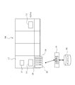
- FIG. 1 is a block diagram schematically showing the configuration of a component mounting line according to the first embodiment of the present invention.
- FIG. 2 is a block diagram illustrating a configuration example of a modular component mounter.
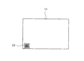
- FIG. 3 is a plan view of a circuit board having a substrate ID code label attached thereto.
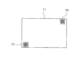
- FIG. 4 is a plan view of a circuit board on which a board ID code label and a temporary board ID code label are attached.
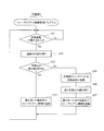
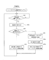
- FIG. 5 is a flowchart showing the flow of processing of the traceability information management program according to the first embodiment.
- FIG. 6 is a flowchart showing the flow of processing of the traceability information management program according to the second embodiment.
- FIGS. 1 A first embodiment of the present invention will be described with reference to FIGS. First, the configuration of the entire component mounting line will be described with reference to FIG.
- a solder printing machine 12, a printing inspection machine 13, a module type component mounting machine 14, a reflow furnace 15, an appearance inspection machine 16 and the like are arranged along the conveyance path of the circuit board 11.
- the module type component mounting machine 14 is configured by arranging a plurality of mounting machine modules 17 in alignment in the conveying direction of the circuit board 11.
- Each mounting machine module 17 includes a conveyor (not shown) that conveys the circuit board 11, a mounting head (not shown) that sucks and mounts components supplied by the feeder 19, and the mounting head.
- a head moving device (not shown) for moving the lens in the X, Y, and Z directions, and a component imaging camera (not shown) for imaging a component adsorbed by a suction nozzle (not shown) of the mounting head from below.
- a mark imaging camera 21 for imaging the reference position mark on the circuit board 11.
- a board ID code label 22 (see FIGS. 3 and 4) in which a board ID (board identification information) is recorded with a one-dimensional code or a two-dimensional code is attached to the circuit board 11 to be carried into the component mounting line. .
- the mark imaging camera 21 of the most upstream mounting machine module 17 of the module type component mounting machine 14 is also used as a code reading unit that images the board ID code label 22 of the circuit board 11 and reads the board ID by image processing.
- the code label feeder 23 is detachably set along with the feeder 19 on the feeder set base 18 of the most upstream mounting machine module 17.
- the code label feeder 23 supplies a temporary substrate ID code label 24 (see FIG. 4) in which a temporary substrate ID (temporary substrate identification information) is recorded with a one-dimensional code or a two-dimensional code.
- a suction nozzle (not shown) held by the mounting head of the most upstream mounting machine module 17 also functions as a code label attaching means, and the temporary board ID code label 24 supplied by the code label feeder 23 is mounted on the mounting machine.
- the module is sucked by the suction nozzle of the module 17 and attached to a predetermined position of the circuit board 11 where the reading of the board ID has failed.
- the temporary board ID code label 24 is stuck at a position away from the sticking position of the board ID code label 22 so that the operator can easily distinguish between the temporary board ID code label 24 and the board ID code label 22. It has become.
- the mark imaging camera 21 of the most upstream mounting machine module 17 is also used as a code reading unit that images the temporary board ID code label 24 and reads the temporary board ID by image processing.
- the operating status of each device such as the modular component mounter 14 constituting the component mounting line is managed by a production management computer 31 that manages the production of the component mounting line.
- the production management computer 31 executes the traceability information management program shown in FIG. 5 so that the board ID read by the mark imaging camera 21 of the most upstream mounting machine module 17 of the modular component mounting machine 14 or a temporary It functions as a traceability information management unit that registers and manages traceability information (for example, used parts, production date / time, used device name, product name, etc.) of the circuit board 11 (component mounting board) in association with the board ID.
- the traceability information management program in FIG. 5 is executed by the production management computer 31 as follows.
- the program waits until the circuit board 11 is carried into the most upstream mounting machine module 17 of the module type component mounting machine 14 in step 101 after the activation.
- the program proceeds to step 102, and the circuit board 11 is used by using the mark imaging camera 21 of the most upstream mounting machine module 17.
- the board ID code label 22 is imaged and the board ID is read by image processing.
- step 103 it is determined whether the substrate ID has been successfully read. If it is determined that the substrate ID has been successfully read, the process proceeds to step 104, where the circuit board 11 is associated with the read substrate ID. Traceability information of (component mounting board) is registered in the database 32 and managed.
- step 103 the process proceeds to step 105 where the temporary substrate ID code label 24 supplied by the code label feeder 23 is used as the suction nozzle of the mounting machine module 17. Is stuck to a predetermined position of the circuit board 11 which has failed to read the board ID. Thereafter, the program proceeds to step 106, and the temporary board ID code label 24 of the circuit board 11 is imaged using the mark imaging camera 21 of the most upstream mounting machine module 17, and the temporary board is obtained by image processing. Read the ID. Thereafter, the program proceeds to step 107, and traceability information of the circuit board 11 (component mounting board) is registered in the database 32 in association with the read temporary board ID.
- the program registers the traceability information of the circuit board 11 (component mounting board) in the database 32 in association with the read board ID or temporary board ID in step 104 or 107 described above, and then returns to step 101 described above. Thereby, this program repeats the process of reading the board ID or the temporary board ID and registering the traceability information in the database 32 every time the circuit board 11 is carried into the most upstream mounting machine module 17.
- the operator takes out the circuit board 11 to which the temporary board ID code label 24 is attached from the circuit board 11 (component mounting board) carried out from the component mounting line, and the board ID of the circuit board 11.
- the code label 22 and the temporary board ID code label 24 are scanned by a code reading device (not shown) such as a bar code reader to read the board ID and temporary board ID of the circuit board 11 and transmit them to the production management computer 31. Then, the ID of the traceability information of the circuit board 11 registered in the database 32 is rewritten from the temporary board ID to the board ID.
- the traceability information management program associates the traceability information of the circuit board 11 with the board ID without stopping production even if the reading of the board ID of the circuit board 11 carried into the component mounting line fails. Can be registered and managed. Even if the reading of the board ID fails due to the printed state of the board ID code label 22 of the circuit board 11 carried into the component mounting line, the operator manually uses the code reader such as a bar code reader to manually set the board ID. If the code label 22 is scanned, the substrate ID can be read.
- the present invention may have a configuration in which an apparatus dedicated to code reading (such as a bar code reader or an external camera) is provided.
- the code label feeder 23 is set on the feeder set base 18 of the most upstream mounting machine module 17 along with the feeder 19 for supplying parts.
- the code label feeder 23 can be set by effectively using the empty slot of the feeder set stand 18, and the requirement for space saving can be satisfied.
- the mounting machine module is used as a code label attaching means for attaching the temporary board ID code label 24 supplied by the code label feeder 23 to a predetermined position of the circuit board 11 in which the board ID reading has failed.
- the code label feeder 23 may be provided with a function as a code label attaching means.
- Embodiment 2 of the present invention will be described with reference to FIG. However, description of the substantially same parts as those in the first embodiment will be omitted or simplified, and different parts will be mainly described.
- the temporary board ID code label 24 attached to the circuit board 11 is attached using the mark imaging camera 21 of the most upstream mounting machine module 17.
- the provisional board ID is read by image processing and image processing
- the traceability information management program of FIG. 6 is executed, and the circuit board 11 that has failed to read the board ID is attached.
- the temporary board ID recorded on the temporary board ID code label 24 is transmitted from the code label feeder 23 to the production management computer 31.
- the traceability information management program in FIG. 6 only changes the processing in step 106 and step 107 of the traceability information management program in FIG. 5 described in the first embodiment to steps 106a and 107a, respectively.
- the process 105 is the same. That is, when reading of the board ID fails, the temporary board ID code label 24 supplied by the code label feeder 23 is attached to a predetermined position of the circuit board 11 where reading of the board ID has failed (step 103 ⁇ 105) Proceeding to step 106a, the temporary board ID recorded on the temporary board ID code label 24 adhered to the circuit board 11 is transmitted from the code label feeder 23 to the production management computer 31. Thereafter, the traceability information management program proceeds to step 107a and registers the traceability information of the circuit board 11 (component mounting board) in the database 32 in association with the received temporary board ID.
- the board ID is read by the most upstream mounting machine module 17 of the module type component mounting machine 14, but upstream of the module type component mounting machine 14 in the component mounting line.
- the present invention may adopt aspects such as laser marking and RFID for the “code label”.
Landscapes
- Engineering & Computer Science (AREA)
- Business, Economics & Management (AREA)
- Physics & Mathematics (AREA)
- General Physics & Mathematics (AREA)
- Manufacturing & Machinery (AREA)
- Theoretical Computer Science (AREA)
- Economics (AREA)
- Operations Research (AREA)
- General Business, Economics & Management (AREA)
- Tourism & Hospitality (AREA)
- Quality & Reliability (AREA)
- Human Resources & Organizations (AREA)
- Marketing (AREA)
- Strategic Management (AREA)
- Microelectronics & Electronic Packaging (AREA)
- General Engineering & Computer Science (AREA)
- General Health & Medical Sciences (AREA)
- Primary Health Care (AREA)
- Automation & Control Theory (AREA)
- Health & Medical Sciences (AREA)
- Development Economics (AREA)
- Entrepreneurship & Innovation (AREA)
- Supply And Installment Of Electrical Components (AREA)
- General Factory Administration (AREA)
Abstract
Description
まず、図1に基づいて部品実装ライン全体の構成を説明する。
尚、上記実施例1,2では、モジュール型部品実装機14の最上流の実装機モジュール17で、基板IDを読み取るようにしたが、部品実装ラインのうちのモジュール型部品実装機14よりも上流側の装置(半田印刷機12等)の基板搬入側に、基板IDを読み取るコード読取り手段と、仮基板IDコードラベルを供給するコードラベルフィーダと、仮基板IDコードラベルを基板IDの読み取りに失敗した回路基板11に貼着するコードラベル貼着手段を配置した構成としても良い。
Claims (7)
- 回路基板に部品を実装する部品実装機を配置した部品実装ラインで生産する部品実装基板のトレーサビリティ情報を管理する部品実装ラインのトレーサビリティ情報管理システムにおいて、
前記部品実装ラインに搬入する回路基板には、基板識別情報(以下「基板ID」という)をコード化して記録した基板IDコードラベルが付与され、
前記部品実装ラインに搬入された回路基板の基板IDコードラベルから基板IDを読み取るコード読取り手段と、
仮の基板IDをコード化して記録した仮基板IDコードラベルを付与するコードラベルフィーダと、
前記コード読取り手段が前記基板IDの読み取りに失敗したときに前記コードラベルフィーダで付与を準備された前記仮基板IDコードラベルを前記基板IDの読み取りに失敗した回路基板に付与するコードラベル付与手段と、
前記コード読取り手段が読み取った前記基板ID又は前記仮の基板IDと関連付けて部品実装基板のトレーサビリティ情報をデータベースに登録して管理するトレーサビリティ情報管理手段と
を備えていることを特徴とする部品実装ラインのトレーサビリティ情報管理システム。 - 回路基板に部品を実装する部品実装機を配置した部品実装ラインで生産する部品実装基板のトレーサビリティ情報を管理する部品実装ラインのトレーサビリティ情報管理システムにおいて、
前記部品実装ラインに搬入する回路基板には、基板識別情報(以下「基板ID」という)をコード化して記録した基板IDコードラベルが貼着され、
前記部品実装ラインに搬入された回路基板の基板IDコードラベルから基板IDを読み取るコード読取り手段と、
仮の基板IDをコード化して記録した仮基板IDコードラベルを供給するコードラベルフィーダと、
前記コード読取り手段が前記基板IDの読み取りに失敗したときに前記コードラベルフィーダで供給された前記仮基板IDコードラベルを前記基板IDの読み取りに失敗した回路基板に貼着するコードラベル貼着手段と、
前記コード読取り手段が読み取った前記基板ID又は前記仮の基板IDと関連付けて部品実装基板のトレーサビリティ情報をデータベースに登録して管理するトレーサビリティ情報管理手段と
を備えていることを特徴とする部品実装ラインのトレーサビリティ情報管理システム。 - 前記部品実装機には、回路基板の基準位置マークを撮像するマーク撮像用のカメラが搭載され、
前記コード読取り手段は、前記マーク撮像用のカメラで前記回路基板の基板IDコードラベルを撮像して画像処理により前記基板IDを読み取り、その基板IDの読み取りに失敗したときに前記コードラベル貼着手段が前記回路基板に貼着した前記仮基板IDコードラベルを前記マーク撮像用のカメラで撮像して画像処理により前記仮の基板IDを読み取ることを特徴とする請求項2に記載の部品実装ラインのトレーサビリティ情報管理システム。 - 前記コードラベルフィーダは、前記基板IDの読み取りに失敗した回路基板に貼着する前記仮基板IDコードラベルに記録されている前記仮の基板IDを前記トレーサビリティ情報管理手段に送信することを特徴とする請求項2に記載の部品実装ラインのトレーサビリティ情報管理システム。
- 前記コードラベル貼着手段として前記部品実装機の吸着ノズルを使用し、前記コードラベルフィーダで供給された前記仮基板IDコードラベルを前記部品実装機の吸着ノズルで吸着して前記基板IDの読み取りに失敗した回路基板に貼着することを特徴とする請求項2乃至4のいずれかに記載の部品実装ラインのトレーサビリティ情報管理システム。
- 前記コードラベルフィーダは、前記部品実装機のフィーダセット台に、部品を供給するフィーダと並べてセットされることを特徴とする請求項2乃至5のいずれかに記載の部品実装ラインのトレーサビリティ情報管理システム。
- 請求項2乃至6のいずれかに記載の部品実装ラインのトレーサビリティ情報管理システムを使用して部品実装基板のトレーサビリティ情報を管理する部品実装ラインのトレーサビリティ情報管理方法において、
作業者は、前記部品実装ラインから搬出された部品実装基板の中から、前記仮基板IDコードラベルが貼着された部品実装基板を取り出して、当該部品実装基板の基板IDコードラベルと仮基板IDコードラベルをコード読取り装置で走査して当該部品実装基板の基板IDと仮の基板IDを読み取って前記トレーサビリティ情報管理手段に送信し、前記データベースに登録された当該部品実装基板のトレーサビリティ情報のIDを前記仮の基板IDから前記基板IDに書き換えることを特徴とする部品実装ラインのトレーサビリティ情報管理方法。
Priority Applications (5)
| Application Number | Priority Date | Filing Date | Title |
|---|---|---|---|
| CN201480076609.5A CN106063400B (zh) | 2014-03-05 | 2014-03-05 | 元件安装线的可追溯性信息管理系统及可追溯性信息管理方法 |
| JP2016506000A JP6231188B2 (ja) | 2014-03-05 | 2014-03-05 | 部品実装ラインのトレーサビリティ情報管理システム及びトレーサビリティ情報管理方法 |
| PCT/JP2014/055648 WO2015132905A1 (ja) | 2014-03-05 | 2014-03-05 | 部品実装ラインのトレーサビリティ情報管理システム及びトレーサビリティ情報管理方法 |
| US15/123,179 US9668395B2 (en) | 2014-03-05 | 2014-03-05 | Component mounting line traceability information management system and traceability information management method |
| EP14884946.6A EP3116293B1 (en) | 2014-03-05 | 2014-03-05 | Traceability information management system and traceability information management method for component mounting line |
Applications Claiming Priority (1)
| Application Number | Priority Date | Filing Date | Title |
|---|---|---|---|
| PCT/JP2014/055648 WO2015132905A1 (ja) | 2014-03-05 | 2014-03-05 | 部品実装ラインのトレーサビリティ情報管理システム及びトレーサビリティ情報管理方法 |
Publications (1)
| Publication Number | Publication Date |
|---|---|
| WO2015132905A1 true WO2015132905A1 (ja) | 2015-09-11 |
Family
ID=54054742
Family Applications (1)
| Application Number | Title | Priority Date | Filing Date |
|---|---|---|---|
| PCT/JP2014/055648 Ceased WO2015132905A1 (ja) | 2014-03-05 | 2014-03-05 | 部品実装ラインのトレーサビリティ情報管理システム及びトレーサビリティ情報管理方法 |
Country Status (5)
| Country | Link |
|---|---|
| US (1) | US9668395B2 (ja) |
| EP (1) | EP3116293B1 (ja) |
| JP (1) | JP6231188B2 (ja) |
| CN (1) | CN106063400B (ja) |
| WO (1) | WO2015132905A1 (ja) |
Cited By (5)
| Publication number | Priority date | Publication date | Assignee | Title |
|---|---|---|---|---|
| FR3060253A1 (fr) * | 2016-12-14 | 2018-06-15 | Speed Print Technology Limited | Procede et dispositif de fabrication de circuit imprime |
| WO2019016923A1 (ja) | 2017-07-20 | 2019-01-24 | 株式会社Fuji | 対基板作業システム |
| WO2019077676A1 (ja) * | 2017-10-17 | 2019-04-25 | 株式会社Fuji | 工作機械装置 |
| JP2023502588A (ja) * | 2019-11-11 | 2023-01-25 | ウエスト ファーマスーティカル サービシーズ インコーポレイテッド | レーザで刻印されたエラストマー部品を製造するシステム及び方法 |
| JP2023018184A (ja) * | 2021-07-27 | 2023-02-08 | パナソニックIpマネジメント株式会社 | 部品データ管理方法、部品データ管理装置、部品データ管理プログラムならびに部品データ管理システム |
Families Citing this family (7)
| Publication number | Priority date | Publication date | Assignee | Title |
|---|---|---|---|---|
| WO2018016018A1 (ja) * | 2016-07-20 | 2018-01-25 | 富士機械製造株式会社 | 部品実装ラインの生産管理システム |
| AU2017225097B2 (en) | 2016-09-09 | 2020-07-23 | Richard L. Hartman | Wakeboat Engine Powered Ballasting Apparatus and Methods |
| CN108693867A (zh) * | 2018-05-21 | 2018-10-23 | 珠海格力电器股份有限公司 | 一种控制器智能追溯管理方法及系统 |
| CN111511113A (zh) * | 2019-01-31 | 2020-08-07 | 鹏鼎控股(深圳)股份有限公司 | 电路板加工系统、装置及方法 |
| IT201900005466A1 (it) * | 2019-04-09 | 2020-10-09 | Preventlab S R L | Metodo per la tracciatura dei processi produttivi di un’apparecchiatura elettronica |
| JP7262300B2 (ja) * | 2019-05-17 | 2023-04-21 | Juki株式会社 | 電子部品実装装置及び電子部品実装方法 |
| CN114692799B (zh) * | 2020-12-31 | 2025-02-07 | 中国纺织科学研究院有限公司 | 一种可重复利用的标签管理方法及管理系统 |
Citations (8)
| Publication number | Priority date | Publication date | Assignee | Title |
|---|---|---|---|---|
| JP2003280713A (ja) * | 2002-03-19 | 2003-10-02 | Dainippon Printing Co Ltd | 製造情報管理システム |
| JP2003295936A (ja) * | 2002-04-05 | 2003-10-17 | Denso Corp | 生産管理方法 |
| US20050086800A1 (en) * | 2003-10-28 | 2005-04-28 | Jeffrey Heidel | Method for improved traceability of components used in manufacturing of a printed circuit board (PCB) |
| WO2007080793A1 (ja) * | 2006-01-11 | 2007-07-19 | Matsushita Electric Industrial Co., Ltd. | 電子部品実装システムおよび電子部品実装方法 |
| JP2009004400A (ja) * | 2007-06-19 | 2009-01-08 | Yamaha Motor Co Ltd | 実装機および部品吸着装置 |
| JP2012068975A (ja) * | 2010-09-24 | 2012-04-05 | Asahi Glass Co Ltd | 管理システムおよび管理方法 |
| JP2013120853A (ja) * | 2011-12-07 | 2013-06-17 | Fuji Mach Mfg Co Ltd | 対回路基板作業機 |
| JP2013149172A (ja) * | 2012-01-20 | 2013-08-01 | Sharp Corp | 物流ラインの構成装置、物流ラインの管理装置、物流ライン管理システム、搬送制御プログラムおよびコンピュータ読み取り可能な記録媒体 |
Family Cites Families (7)
| Publication number | Priority date | Publication date | Assignee | Title |
|---|---|---|---|---|
| US4667403A (en) * | 1984-05-16 | 1987-05-26 | Siemens Aktiengesellschaft | Method for manufacturing electronic card modules |
| JP4360327B2 (ja) * | 2005-02-10 | 2009-11-11 | パナソニック株式会社 | 電子部品実装装置および基板情報印加装置ならびに基板情報印加方法 |
| JP4994105B2 (ja) * | 2007-05-10 | 2012-08-08 | 富士機械製造株式会社 | 回路基板の生産管理方法 |
| JP2011049478A (ja) | 2009-08-28 | 2011-03-10 | Jisso Kk | プリント配線基板のトレーサビリティー管理システム |
| CN103298325B (zh) * | 2012-03-02 | 2017-05-17 | Juki株式会社 | 电子电路生产履历管理系统、方法及电子部件安装装置 |
| JP5277334B2 (ja) | 2012-04-20 | 2013-08-28 | Juki株式会社 | 電子部品実装装置のライン制御装置 |
| JP5903583B2 (ja) | 2012-05-08 | 2016-04-13 | パナソニックIpマネジメント株式会社 | 電子部品実装システムおよび電子部品実装システムにおける生産履歴情報生成方法 |
-
2014
- 2014-03-05 EP EP14884946.6A patent/EP3116293B1/en active Active
- 2014-03-05 JP JP2016506000A patent/JP6231188B2/ja active Active
- 2014-03-05 US US15/123,179 patent/US9668395B2/en active Active
- 2014-03-05 WO PCT/JP2014/055648 patent/WO2015132905A1/ja not_active Ceased
- 2014-03-05 CN CN201480076609.5A patent/CN106063400B/zh active Active
Patent Citations (8)
| Publication number | Priority date | Publication date | Assignee | Title |
|---|---|---|---|---|
| JP2003280713A (ja) * | 2002-03-19 | 2003-10-02 | Dainippon Printing Co Ltd | 製造情報管理システム |
| JP2003295936A (ja) * | 2002-04-05 | 2003-10-17 | Denso Corp | 生産管理方法 |
| US20050086800A1 (en) * | 2003-10-28 | 2005-04-28 | Jeffrey Heidel | Method for improved traceability of components used in manufacturing of a printed circuit board (PCB) |
| WO2007080793A1 (ja) * | 2006-01-11 | 2007-07-19 | Matsushita Electric Industrial Co., Ltd. | 電子部品実装システムおよび電子部品実装方法 |
| JP2009004400A (ja) * | 2007-06-19 | 2009-01-08 | Yamaha Motor Co Ltd | 実装機および部品吸着装置 |
| JP2012068975A (ja) * | 2010-09-24 | 2012-04-05 | Asahi Glass Co Ltd | 管理システムおよび管理方法 |
| JP2013120853A (ja) * | 2011-12-07 | 2013-06-17 | Fuji Mach Mfg Co Ltd | 対回路基板作業機 |
| JP2013149172A (ja) * | 2012-01-20 | 2013-08-01 | Sharp Corp | 物流ラインの構成装置、物流ラインの管理装置、物流ライン管理システム、搬送制御プログラムおよびコンピュータ読み取り可能な記録媒体 |
Cited By (12)
| Publication number | Priority date | Publication date | Assignee | Title |
|---|---|---|---|---|
| FR3060253A1 (fr) * | 2016-12-14 | 2018-06-15 | Speed Print Technology Limited | Procede et dispositif de fabrication de circuit imprime |
| WO2019016923A1 (ja) | 2017-07-20 | 2019-01-24 | 株式会社Fuji | 対基板作業システム |
| JPWO2019016923A1 (ja) * | 2017-07-20 | 2020-03-19 | 株式会社Fuji | 対基板作業システム |
| US11010576B2 (en) | 2017-07-20 | 2021-05-18 | Fuji Corporation | Substrate work system |
| WO2019077676A1 (ja) * | 2017-10-17 | 2019-04-25 | 株式会社Fuji | 工作機械装置 |
| JPWO2019077676A1 (ja) * | 2017-10-17 | 2020-01-23 | 株式会社Fuji | 工作機械装置 |
| JP7032030B2 (ja) | 2017-10-17 | 2022-03-08 | 株式会社Fuji | 工作機械装置 |
| US11513502B2 (en) | 2017-10-17 | 2022-11-29 | Fuji Corporation | Machine tool apparatus for applying information to a surface of a workpiece during manufacturing-related operations |
| JP2023502588A (ja) * | 2019-11-11 | 2023-01-25 | ウエスト ファーマスーティカル サービシーズ インコーポレイテッド | レーザで刻印されたエラストマー部品を製造するシステム及び方法 |
| JP7678804B2 (ja) | 2019-11-11 | 2025-05-16 | ウエスト ファーマスーティカル サービシーズ インコーポレイテッド | レーザで刻印されたエラストマー部品を製造するシステム及び方法 |
| JP2023018184A (ja) * | 2021-07-27 | 2023-02-08 | パナソニックIpマネジメント株式会社 | 部品データ管理方法、部品データ管理装置、部品データ管理プログラムならびに部品データ管理システム |
| JP7702638B2 (ja) | 2021-07-27 | 2025-07-04 | パナソニックIpマネジメント株式会社 | 部品データ管理方法、部品データ管理装置、部品データ管理プログラムならびに部品データ管理システム |
Also Published As
| Publication number | Publication date |
|---|---|
| JP6231188B2 (ja) | 2017-11-15 |
| US9668395B2 (en) | 2017-05-30 |
| EP3116293B1 (en) | 2020-02-26 |
| JPWO2015132905A1 (ja) | 2017-03-30 |
| CN106063400B (zh) | 2019-06-25 |
| CN106063400A (zh) | 2016-10-26 |
| EP3116293A4 (en) | 2017-11-01 |
| US20170079169A1 (en) | 2017-03-16 |
| EP3116293A1 (en) | 2017-01-11 |
Similar Documents
| Publication | Publication Date | Title |
|---|---|---|
| JP6231188B2 (ja) | 部品実装ラインのトレーサビリティ情報管理システム及びトレーサビリティ情報管理方法 | |
| US8849442B2 (en) | Component mounting line and component mounting method | |
| JP5903583B2 (ja) | 電子部品実装システムおよび電子部品実装システムにおける生産履歴情報生成方法 | |
| US9332684B2 (en) | Electronic component mounting system | |
| US10793388B2 (en) | Feeder arrangement support system and method for supporting feeder arrangement | |
| CN103379742A (zh) | 电子元件安装系统 | |
| US10863657B2 (en) | Electronic component mounting method | |
| US20080243438A1 (en) | Maintenance information managing apparatus for component mounting machine | |
| CN103298325B (zh) | 电子电路生产履历管理系统、方法及电子部件安装装置 | |
| WO2015122011A1 (ja) | 対基板作業システム | |
| US11010576B2 (en) | Substrate work system | |
| CN111108823B (zh) | 元件安装线的安装精度测定系统及安装精度测定方法 | |
| JP4710851B2 (ja) | 電子部品実装システムおよび電子部品実装方法 | |
| JP5003694B2 (ja) | 部品実装ライン及び部品実装方法 | |
| JP2014154650A (ja) | 電子部品実装システムおよびキャリア識別方法 | |
| CN107438358A (zh) | 部件安装系统、部件安装方法以及部件安装装置 | |
| JP6630729B2 (ja) | 部品実装システム | |
| JP2011124329A (ja) | 両面実装基板の生産方法 | |
| JP2012119511A (ja) | 電子部品装着装置、電子部品装着装置システム、および、電子部品装着方法 | |
| JP6753657B2 (ja) | 基板作業システム | |
| JP2010092955A (ja) | 部品実装機、吸着ノズル及び吸着ノズルの識別方法 | |
| JP4981501B2 (ja) | 電子部品装着方法 | |
| KR20080003634A (ko) | 표면실장용 테이프, 표면실장 시스템 및 이를 이용한표면실장 방법 | |
| CN104488373B (zh) | 安装系统 | |
| JP2012134304A (ja) | 電子部品装着装置、および、電子部品装着システム |
Legal Events
| Date | Code | Title | Description |
|---|---|---|---|
| 121 | Ep: the epo has been informed by wipo that ep was designated in this application |
Ref document number: 14884946 Country of ref document: EP Kind code of ref document: A1 |
|
| ENP | Entry into the national phase |
Ref document number: 2016506000 Country of ref document: JP Kind code of ref document: A |
|
| WWE | Wipo information: entry into national phase |
Ref document number: 15123179 Country of ref document: US |
|
| REEP | Request for entry into the european phase |
Ref document number: 2014884946 Country of ref document: EP |
|
| WWE | Wipo information: entry into national phase |
Ref document number: 2014884946 Country of ref document: EP |
|
| NENP | Non-entry into the national phase |
Ref country code: DE |