WO2015133134A1 - ロータ - Google Patents
ロータ Download PDFInfo
- Publication number
- WO2015133134A1 WO2015133134A1 PCT/JP2015/001145 JP2015001145W WO2015133134A1 WO 2015133134 A1 WO2015133134 A1 WO 2015133134A1 JP 2015001145 W JP2015001145 W JP 2015001145W WO 2015133134 A1 WO2015133134 A1 WO 2015133134A1
- Authority
- WO
- WIPO (PCT)
- Prior art keywords
- hole
- rotor core
- magnet
- magnetic flux
- base
- Prior art date
- Legal status (The legal status is an assumption and is not a legal conclusion. Google has not performed a legal analysis and makes no representation as to the accuracy of the status listed.)
- Ceased
Links
Images



Classifications
-
- H—ELECTRICITY
- H02—GENERATION; CONVERSION OR DISTRIBUTION OF ELECTRIC POWER
- H02K—DYNAMO-ELECTRIC MACHINES
- H02K1/00—Details of the magnetic circuit
- H02K1/06—Details of the magnetic circuit characterised by the shape, form or construction
- H02K1/22—Rotating parts of the magnetic circuit
- H02K1/27—Rotor cores with permanent magnets
- H02K1/2706—Inner rotors
- H02K1/272—Inner rotors the magnetisation axis of the magnets being perpendicular to the rotor axis
- H02K1/274—Inner rotors the magnetisation axis of the magnets being perpendicular to the rotor axis the rotor consisting of two or more circumferentially positioned magnets
- H02K1/2753—Inner rotors the magnetisation axis of the magnets being perpendicular to the rotor axis the rotor consisting of two or more circumferentially positioned magnets the rotor consisting of magnets or groups of magnets arranged with alternating polarity
- H02K1/276—Magnets embedded in the magnetic core, e.g. interior permanent magnets [IPM]
-
- H—ELECTRICITY
- H02—GENERATION; CONVERSION OR DISTRIBUTION OF ELECTRIC POWER
- H02K—DYNAMO-ELECTRIC MACHINES
- H02K1/00—Details of the magnetic circuit
- H02K1/02—Details of the magnetic circuit characterised by the magnetic material
-
- H—ELECTRICITY
- H02—GENERATION; CONVERSION OR DISTRIBUTION OF ELECTRIC POWER
- H02K—DYNAMO-ELECTRIC MACHINES
- H02K2213/00—Specific aspects, not otherwise provided for and not covered by codes H02K2201/00 - H02K2211/00
- H02K2213/03—Machines characterised by numerical values, ranges, mathematical expressions or similar information
Definitions
- the present invention relates to the structure of a rotor.
- An embedded magnet-structured synchronous motor (IPMSM: Interior Permanent Magnet Synchronous Motor) includes a stator and a rotor.
- the rotor includes a rotor core provided with magnet embedding holes at equal intervals in the circumferential direction, and a permanent magnet embedded in the magnet embedding holes.
- the stator has a stator core in which coils are wound at a plurality of locations. Thereby, according to the rotating magnetic field formed by the electric current which flows into a coil, a rotor and a stator repeat repulsion and attraction
- the rotor core according to Patent Document 1 is provided with a magnetic flux short-circuit prevention hole so as to extend from the both circumferential ends of the magnet embedding hole to the outer peripheral surface side of the rotor core and along the outer periphery of the rotor core. . Due to the magnetic flux short-circuit prevention hole, the magnetic flux that contributes to the magnet torque flows from the permanent magnet to the outer peripheral surface side of the rotor core. The magnetic flux short-circuit prevention hole limits the flow of the d-axis magnetic flux caused by the winding that contributes to the reluctance torque.
- the q-axis magnetic flux generated by the winding that also contributes to the reluctance torque flows into the rotor core from the outer peripheral surface side of the rotor core. Since the magnetic flux short-circuit prevention hole is located particularly in the inflow portion to the rotor core in the magnetic path of the q-axis magnetic flux in the rotor core, it prevents the q-axis magnetic flux from flowing into the rotor core. As a result, the q-axis magnetic flux decreases, and the reluctance torque generated based on the difference between the q-axis inductance and the d-axis inductance decreases as a result.
- the present invention has been made in view of such a point, and an object thereof is to obtain a good magnet torque while preventing a decrease in the reluctance torque to be generated.
- the circumferential direction of the rotor core (31) from at least one of the opposing peripheral portions (35a, 35a) of the base holes (35) provided at both ends of the magnet embedding hole (32)
- a convex hole (36) projecting into the base hole (35) is further formed, and the convex hole (36) is more for embedding the magnet than the outer peripheral end (35b) of the base hole (35). It is located on the hole (32) side.
- the rotor core (31) is formed with a magnet embedding hole (32) and a base hole (35) extending from both ends of the hole (32) to the outer periphery of the rotor core (31). That is, when viewed from the axial direction, the magnet embedding hole (32) and the base hole (35) have a shape protruding toward the inner peripheral side of the rotor core (31).
- the rotor core (31) is further formed with a convex hole (36) as a part constituting the gap (34) together with the base hole (35).
- the convex hole (36) has a shape projecting in the circumferential direction of the rotor core (31) from the opposite peripheral edge portions (35a, 35a) of the base holes (35) at both ends of the magnet embedding hole (32). It has become. Moreover, the convex hole (36) is located closer to the magnet embedding hole (32) side, that is, the permanent magnet (39) side than the outer peripheral side tip (35b) of the base hole (35).
- the convex hole (36) is not located in the portion where the q-axis magnetic flux ⁇ q by the winding flows into the rotor core (31), the q-axis magnetic flux ⁇ q is not lowered. Furthermore, since the convex hole (36) has a shape protruding in the circumferential direction of the rotor core (31) from the opposing peripheral edge portions (35a, 35a) of the base holes (35), the d-axis magnetic flux ⁇ d due to the windings The magnetic flux ⁇ m can be concentrated and flowed from the permanent magnet (39) to the outer peripheral side of the rotor core (31).
- the magnet torque generated based on the magnet magnetic flux ⁇ m is good, and the reluctance torque generated based on the inductances of the q-axis magnetic flux ⁇ q and the d-axis magnetic flux ⁇ d can be prevented.
- the second aspect of the present disclosure is characterized in that, in the first aspect, the rotor core (31) is formed with the convex hole (36) continuously with the base hole (35).
- the convex hole (36) and the base hole (35) are connected to each other so that the rotor core (31) is formed. Therefore, it is possible to reduce the occurrence of so-called short-circuit magnetic flux leakage, in which a part of the magnet magnetic flux ⁇ m is separated from the flow of the magnetic magnetic flux ⁇ m and penetrates the gap (34).
- the base hole (35) and the convex hole (36) are continuous, it is easy to form the base hole (35) and the convex hole (36) in the rotor core (31) when manufacturing the rotor (30). Become.
- the rotor core (31) includes a base of the peripheral portion (35a, 35a) and the convex hole (36) corresponding to the peripheral portion (35a, 35a). It has the connection part (31b) which connects a hole side peripheral part (36c), It is characterized by the above-mentioned.
- a fourth aspect of the present disclosure is characterized in that, in any one of the first aspect to the third aspect, the convex hole (36) has a semicircular shape when viewed in the axial direction.
- the shape of the convex hole (36) when viewed in the axial direction is a semicircular shape with no corners. Therefore, the local magnetic flux saturation which may occur when the convex hole (36) has a corner portion can be prevented, and the q-axis magnetic flux ⁇ q caused by the winding can flow smoothly.
- the rotor core (31) is made of a magnetic material having a saturation magnetic flux density of 2.3 T or more. It is characterized by.
- the protruding length (w1) of the convex hole (36) is the circumferential direction of the base hole (35). It is characterized by being larger than the width (w2).
- the convex hole (36) is provided at each of both ends of the magnet embedding hole (32).
- the base hole (35) is formed only corresponding to the base hole (35) positioned on the forward side in the rotational direction of the rotor core (31).
- the magnet magnetic flux ⁇ m can be transferred to the permanent magnet (39) without obstructing the flow of the q-axis magnetic flux ⁇ q by the winding near the outer peripheral surface of the rotor core (31) corresponding to the forward base hole (35) in the rotation direction. ) From the outer periphery of the rotor core (31). Therefore, the magnetic flux density generated in the air gap (G) can be increased. Accordingly, it is possible to increase the reluctance torque generated based on the magnet torque and the q-axis inductance caused by the magnet magnetic flux ⁇ m.
- the magnet torque generated based on the magnet magnetic flux ⁇ m is good, and the decrease in the reluctance torque generated based on the respective inductances of the q-axis magnetic flux ⁇ q and the d-axis magnetic flux ⁇ d can be prevented. it can.
- the second aspect it is possible to reduce the occurrence of so-called short-circuit magnetic flux leakage, and at the time of manufacturing the rotor (30), the base hole (35) and the convex hole (36) to the rotor core (31).
- the formation of is simplified.
- the deformation of the convex hole (36) due to the centrifugal force is suppressed, the deformation of the portion (31a) of the rotor core (31) can be suppressed.
- high torque can be generated in the rotor (20) during rotation.
- the seventh aspect it is possible to increase the reluctance torque generated based on the magnet torque and the q-axis inductance caused by the magnet magnetic flux ⁇ m.
- FIG. 1 is a cross-sectional view of a motor including a rotor according to the first embodiment.
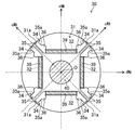
- FIG. 2 is a diagram in which the rotor and the drive shaft are extracted from FIG.
- FIG. 3 is an enlarged view of a portion of the rotor of FIG.
- FIG. 4 is an enlarged view of a part of a conventional rotor.
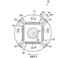
- FIG. 5 is a cross-sectional view of the rotor and the drive shaft according to the second embodiment.
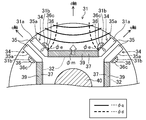
- FIG. 6 is a cross-sectional view of the rotor and the drive shaft according to the third embodiment.
- FIG. 1 is a cross-sectional view of a motor (10) including a rotor (30) according to Embodiment 1 of the present invention.
- This motor (10) is used for a compressor motor of an air conditioner, for example.
- the motor (10) is a synchronous motor (so-called IPMSM) in which a magnet is embedded in the rotor (30). As shown in FIG. 1, the motor (10) includes a stator (20), a rotor (30), and a drive shaft (40), and is accommodated in a casing (50) of the compressor.
- IPMSM synchronous motor
- the axial direction is the rotational axis direction of the motor (10) and represents the direction of the axis (O) of the drive shaft (40).
- the radial direction represents a direction orthogonal to the axis (O), particularly the radial direction of the motor (10).
- the outer peripheral side represents the side far from the axis (O)
- the inner peripheral side represents the side close to the axis (O).
- the stator (20) includes a cylindrical stator core (21) and a coil (26).
- the stator core (21) is a laminated core obtained by punching an electromagnetic steel sheet by pressing to form a planar laminated board and laminating a large number of laminated boards in the axial direction. As shown in FIG. 1, the stator core (21) has one back yoke portion (22), a plurality of teeth portions (23), and a plurality of flange portions (24).
- the teeth portion (23) is a rectangular parallelepiped portion extending in the radial direction in the stator core (21).
- Each of the plurality of tooth portions (23) is disposed along the circumferential direction of the stator core (21) and at substantially equal intervals.
- the space between the teeth portions (23) is a coil slot (25) in which the coil (26) is accommodated.
- the back yoke part (22) has an annular shape.
- the back yoke portion (22) connects the teeth portions (23) on the outer peripheral side of the teeth portion (23).
- the outer peripheral part of the back yoke part (22) is fixed to the inner surface of the casing (50) of the compressor.
- the brim portion (24) is a portion connected to the inner peripheral side of each tooth portion (23).
- the length of the circumferential flange portion (24) of the stator core (21) is larger than the circumferential length of the teeth portion (23).
- the inner peripheral surface of the plurality of brim portions (24) is a cylindrical surface when viewed in the axial direction. The cylindrical surface opposes the outer peripheral surface of the rotor core (31) described later at a predetermined distance. This predetermined distance is called an air gap (G).
- the coil (26) is wound around the teeth part (23).
- the winding method of the coil (26) mainly includes a distributed winding method and a concentrated winding method.
- the rotor (30) includes a cylindrical rotor core (31) and a plurality of permanent magnets (39), and has a cylindrical shape extending in the axial direction.
- the rotor (30) generates magnet torque by the permanent magnet (39) and also generates reluctance torque by the rotor core (31).
- the rotor (30) has four magnetic poles, and the permanent magnet (39) is provided for each magnetic pole.
- the permanent magnet (39) is embedded in a later-described magnet slot (32) in the rotor core (31).
- the rotor core (31) is a laminated core formed by punching an electromagnetic steel sheet by press working to create a laminated board and laminating a plurality of laminated boards in the axial direction.
- the saturation magnetic flux density of the magnetic steel sheet which is the magnetic material of the rotor core (31) of the first embodiment, is 2.3 T or more. Examples of the magnetic material include a silicon steel plate and permendur.
- a hole for attaching the drive shaft (40) is formed at the center of the rotor core (31).
- the rotor core (31) is fitted and fixed to the drive shaft (40) inserted into the hole, and can rotate together with the drive shaft (40).
- the rotor core (31) is formed with a plurality of magnet slots (32) (corresponding to magnet embedding holes) and a plurality of gaps (34). Magnet slots (32) and air gaps (34) are provided in the rotor core (31) for each magnetic pole so that one magnetic slot (32) and two air gaps (34) correspond to one magnetic pole. It has been.
- the magnet slot (32) is formed in the rotor core (31) side by side in the circumferential direction of the rotor core (31) and penetrates in the axial direction.
- the magnet slots (32) have an elongated rectangular shape when viewed in the axial direction, and are arranged at a pitch of about 90 degrees around the axis (O). Accordingly, the longitudinal directions of adjacent magnet slots (32) are orthogonal to each other.
- the permanent magnet (39) is embedded in each magnet slot (32).
- the permanent magnets (39) are arranged so that the magnetic poles of the adjacent permanent magnets (39) have opposite directions.
- the air gap (34) is formed in the rotor core (31) continuously with each magnet slot (32) at each longitudinal end of each magnet slot (32). That is, the air gap (34) is located between the adjacent permanent magnets (39) in the rotor core (31) in which the permanent magnets (39) are embedded.
- the gap (34) according to the first embodiment has a shape including a base hole (35) and a convex hole (36).
- the base hole (35) extends from both circumferential ends (more specifically, both longitudinal ends) of the magnet slots (32) to the outer circumferential side of the rotor core (31).
- the outer peripheral side tip (35b), which is the tip, is close to the outer peripheral surface of the rotor core (31).
- the base hole (35) has an elongated rectangular shape extending in the radial direction when viewed in the axial direction.
- the outer peripheral side tip (35b) of the base hole (35) faces the outer peripheral surface of the rotor core (31) through the bridge portion (31a) of the rotor core (31).
- the magnet slot (32) and the base hole (35) have a shape protruding in a substantially U-shape (37) from the outer peripheral side of the rotor core (31) toward the inner peripheral side when viewed in the axial direction.
- the circumferential width of the bridge portion (31a) is preferably determined as appropriate in consideration of the mechanical strength of the rotor core (31), the magnetic flux density of the q-axis magnetic flux (described later) in the winding, and the like.
- the base hole (35) has a function as a so-called barrier portion that prevents a short circuit of magnetic flux by the permanent magnet (39) in the rotor core (31).
- the convex hole (36) is a hole formed in the rotor core (31) so as to be continuous with the base hole (35).
- the convex holes (36) are arranged in the circumferential direction of the rotor core (31) from the opposing peripheral edge portions (35a, 35a) of the base holes (35) provided at both ends of the magnet slot (32) when viewed in the axial direction. It is the hole which protruded in.
- the convex hole (36) extends from each of the two base holes (35) provided corresponding to one magnet slot (32) to the magnet slot (32) side, that is, the magnet slot (32) and Two holes are provided on the inner side of the substantially U-shape (37) taken by the base hole (35), and two holes are provided for one magnetic pole formed on the rotor core (31). That is, a convex hole (36) is formed by enlarging a part of the base hole (35) to the inner side of the substantially U-shape (37), and the base hole (35) and the convex hole (36) are formed. It can be said that one gap (34) is formed as a unit.
- the convex hole (36) is located closer to the magnet slot (32) than the outer peripheral side tip (35b) of the base hole (35). More specifically, the convex hole (36) is located in the vicinity of the magnet side tip (35c) or the magnet side tip (35c) of the base hole (35). For example, the convex hole (36) is located closer to the permanent magnet (39) than the center of the base hole (35) in the radial direction (ie, the length in the longitudinal direction) (thin broken line in FIG. 3). is doing.
- the convex hole (36) has an approximately semicircular shape when viewed in the axial direction.
- the gap (34) has a portion of the base hole (35) near the permanent magnet (39) protruding by the convex hole (36), while the portion on the outer peripheral surface side. Can be said to have a concave configuration compared to the convex hole (36).
- a magnetic flux ⁇ m represented by a white arrow in FIG. 3 flows as a magnetic flux contributing to the magnet torque.
- the magnet magnetic flux ⁇ m is a magnetic flux that flows from the permanent magnet (39) toward the outer peripheral side of the rotor core (31) (that is, the air gap G side in FIG. 1).
- the air gap G is flowed in a concentrated manner toward the upper part of the permanent magnet (39) (the outer peripheral side of the rotor core (31)) in FIG. It is desirable to increase the magnetic flux density inside.
- the magnet slot (32) As a means for causing the magnetic flux ⁇ m to flow intensively toward the upper side of the permanent magnet (39) (the outer peripheral side of the rotor core (31)), the magnet slot (32)
- the portion of the base hole (35) extending along the outer peripheral surface of the rotor core (31) serves as a magnetic barrier, so that the magnetic flux ⁇ m flows concentratedly above the permanent magnet (39).
- reluctance torque is further generated in the rotor core (31).
- the central axis of the permanent magnet (39) is the d axis
- the axis that is electrically and magnetically orthogonal to the d axis that is, the axis passing between adjacent permanent magnets (39)
- the q axis is the q axis.
- the reluctance torque generated in the rotor core (31) increases as the difference “Lq ⁇ Ld” between the q-axis inductance Lq of the q-axis magnetic flux ⁇ q and the d-axis inductance Ld of the d-axis magnetic flux ⁇ d increases. Therefore, in order to increase the reluctance torque, it is preferable to increase the q-axis magnetic flux ⁇ q and decrease the d-axis magnetic flux ⁇ d.
- a portion (35f) of the base hole (35) serving as a magnetic barrier is located. Then, this portion (35f) prevents the flow of the q-axis magnetic flux ⁇ q that should flow into the rotor core (31) from the air gap (G) side. Therefore, in FIG. 4, it is difficult to obtain a good reluctance torque due to a decrease in the q-axis inductance Lq accompanying a decrease in the q-axis magnetic flux ⁇ q.
- the gap (34) according to the first embodiment has a shape composed of the base hole (35) and the convex hole (36).
- the convex hole (36) is closer to the magnet slot (32) than the outer peripheral tip (35b) of the base hole (35) and is closer to the magnet side of the base hole (35). It is located in the vicinity of the tip (35c) or the magnet side tip (35c). That is, the convex hole (36) according to the first embodiment is not located at the inlet of the q-axis magnetic flux ⁇ q in the rotor core (31).
- the convex hole (36) which concerns on this Embodiment 1 from each of the two base holes (35) provided corresponding to one slot (32) for magnets from the slot (32 for magnets) in an axial view.
- Side that is, a hole protruding to the inner side of the substantially U-shaped (37) taken by the magnet slot (32) and the base hole (35).
- the convex hole (36) Similar to the base hole (35), the convex hole (36) has a function as a magnetic barrier by increasing the magnetic resistance. Therefore, the flow of the d-axis magnetic flux ⁇ d related to the winding is limited by the convex hole (36) and the base hole (35). As a result, the d-axis magnetic flux ⁇ d decreases (thick broken line in FIG. 3), and the d-axis inductance Ld decreases.
- the difference between the q-axis inductance Lq and the d-axis inductance Ld is larger than that in FIG. 4, and the reluctance torque is increased as compared with FIG.
- the convex hole (36) protrudes from the base hole (35) toward the magnet slot (32) when viewed in the axial direction. Is guided to the upper side of the permanent magnet (39) of FIG. 3 (the outer peripheral side of the rotor core (31)) by the convex holes (36) without being dispersed. Therefore, a high magnetic flux density in the air gap (G) is maintained.
- the air gap (34) according to the first embodiment is expanded toward the permanent magnet (39) in the vicinity of the permanent magnet (39), and the convex hole (36) is continuous with the base hole (35). Since it is formed in the rotor core (31), it can be said that the magnetic resistance is higher than that in FIG. 4 in the vicinity of the permanent magnet (39). Therefore, the amount of magnetic flux of so-called short-circuit magnetic flux leakage ( ⁇ e in FIG. 3) in which a part of the magnet magnetic flux ⁇ m is separated from the flow of the magnet magnetic flux ⁇ m and penetrates the gap (34) is also shown in FIG. 4 ( ⁇ e in FIG. 4). It decreases compared with. Therefore, a decrease in magnet torque can be suppressed.
- the convex hole (36) is located not near the outer peripheral surface of the rotor core (31) but near the permanent magnet (39) of the base hole (35). ing. Therefore, the bridge portion (31a) of the rotor core (31) according to the first embodiment is shorter than that in FIG. 4, and the mechanical strength of the rotor core (31) is higher than that in FIG. Therefore, even if the centrifugal force accompanying rotation acts, the possibility that the vicinity of the bridge portion (31a) in FIG. 3 is deformed in the radial direction is lower than that in FIG.
- the protrusion length (w1) of the convex hole (36) depends on the magnetic flux density and magnetic path of various magnetic fluxes ⁇ q, ⁇ d, ⁇ m, and ⁇ e as well as the performance of the electromagnetic steel plate and permanent magnet forming the rotor core (31). It is determined.
- the peripheral portion (36a) on the permanent magnet (39) side of the convex hole (36) is slightly closer to the center of the permanent magnet (39) with respect to the longitudinal end (39a) of the permanent magnet (39).
- the radius of the semicircular convex hole (36) is determined to the extent that it is positioned, and the radius is the protruding length (w1).
- the convex hole (36) has a semicircular shape having a radius such that the peripheral portion (36a) on the permanent magnet (39) side, which can be said to be a rising portion, is slightly located in the magnetic path of the magnetic flux ⁇ m.
- the peripheral edge portion (36a) of the convex hole (36) is located closer to the center of the permanent magnet (39), and the convex hole (36) Expand. Therefore, both the short-circuit magnetic flux leakage ⁇ e and the d-axis magnetic flux ⁇ d can be further reduced. However, if the convex hole (36) is enlarged too much, the magnetic paths of the magnet magnetic flux ⁇ m and the q-axis magnetic flux ⁇ q are narrowed.
- the convex hole (36) will further erode the magnetic path of the magnet magnetic flux ⁇ m, and the peripheral part (36b) of the convex hole (36) far from the permanent magnet (39) is the outer peripheral surface of the rotor core (31). Because it will be close to. Further, when the peripheral portion (36b) of the convex hole (36) comes close to the outer peripheral surface of the rotor core (31) due to the enlargement of the convex hole (36), the distance between the outer peripheral surface of the rotor core (31) and the convex hole (36) is increased. There is also a possibility that the mechanical strength of the rotor core (31) may be reduced due to the narrower width.
- the protrusion length (w1) of the convex hole (36) does not hinder the flow of the q-axis magnetic flux ⁇ q into the rotor core (31), suppresses the flow of the d-axis magnetic flux ⁇ d, and further various other magnetic fluxes. It is preferable to determine in consideration of the balance of ⁇ m and ⁇ e and the mechanical strength of the rotor core (31).
- the protruding length (w1) of the convex hole (36) is the circumferential width (w2) of the base hole (35) (that is, the short side direction of the base hole (35) in FIG. 3).
- the width is larger than Therefore, the magnetic resistance of the convex hole (36) is increased by that amount, and the occurrence of short-circuit magnetic flux leakage ⁇ e can be reduced.
- the rotor core (31) of the first embodiment is formed with a magnet slot (32) and a base hole (35) extending from both ends of the magnet slot (32) to the outer periphery of the rotor core (31). Yes. That is, when viewed from the axial direction, the magnet slot (32) and the base hole (35) have a shape protruding toward the inner peripheral side of the rotor core (31).
- the rotor core (31) is further formed with a convex hole (36) as a part constituting the gap (34) together with the base hole (35).
- the convex hole (36) has a shape protruding in the circumferential direction of the rotor core (31) from the peripheral edge portions (35a, 35a) of the base holes (35) facing each other at both ends of the magnet slot (32). . Moreover, the convex hole (36) is located on the magnet slot (32) side, that is, on the permanent magnet (39) side with respect to the outer peripheral side tip (35b) of the base hole (35).
- the convex hole (36) is not located in the portion where the q-axis magnetic flux ⁇ q by the winding flows into the rotor core (31), the q-axis magnetic flux ⁇ q is not lowered. Furthermore, since the convex hole (36) has a shape protruding in the circumferential direction of the rotor core (31) from the opposing peripheral edge portions (35a, 35a) of the base holes (35), the d-axis magnetic flux ⁇ d due to the windings The magnetic flux ⁇ m can be concentrated and flowed from the permanent magnet (39) to the outer peripheral side of the rotor core (31).
- the magnet torque generated based on the inductance of the magnet magnetic flux ⁇ m is good, and the reluctance torque generated based on the inductances of the q-axis magnetic flux ⁇ q and the d-axis magnetic flux ⁇ d can be prevented.
- the convex hole (36) is located closer to the magnet slot (32) than the outer peripheral side tip (35b) of the base hole (35). Therefore, the bridge portion (31a) of the rotor core (31) is shorter than that in FIG. 4, and the mechanical strength of the rotor core (31) is higher than that in FIG. Therefore, even if the centrifugal force accompanying rotation acts, the possibility that the vicinity of the bridge portion (31a) is deformed in the radial direction is lower than that in FIG.
- the gap (34) is constituted not only by the base hole (35) but also by the convex hole (36). Therefore, it can be said that the distance of the air gap (34) as the magnetic barrier is larger than that in FIG. Therefore, the short-circuit magnetic flux leakage ⁇ e is less likely to occur as compared with FIG.
- the convex hole (36) and the base hole (35) are connected to each other, and the rotor core (31) is formed. Therefore, the occurrence of short-circuit magnetic flux leakage ⁇ e can be further reduced.
- the base hole (35) and the convex hole (36) are continuous, it is easy to form the base hole (35) and the convex hole (36) in the rotor core (31) when manufacturing the rotor (30). Become.
- the shape of the convex hole (36) when viewed in the axial direction is a semicircular shape having no corners. As a result, local magnetic flux saturation that may occur when the convex hole (36) has a corner portion can be prevented, and the q-axis magnetic flux ⁇ q caused by the winding can flow smoothly.
- the rotor core (31) of the first embodiment is made of a magnetic material having a saturation magnetic flux density of 2.3 T or more. Accordingly, a high torque is generated in the rotor (30) during rotation.
- the protruding length (w1) of the convex hole (36) is larger than the circumferential width (w2) of the base hole (35). It can be said that the magnetoresistance is increased accordingly. Therefore, the occurrence of short-circuit magnetic flux leakage ⁇ e can be further reduced.
- Embodiment 2 >>
- the convex holes (36) correspond to the two base holes (35) located at both ends of one magnet slot (32). The case where it is provided has been described.
- the convex hole (36) corresponds to one of the two base holes (35) located at both ends of one magnet slot (32). The case where one is provided will be described. That is, in the second embodiment, one convex hole (36) is provided for one magnetic pole formed on the rotor core (31).
- a base hole (35) is provided at each end of one magnet slot (32), and the convex hole (36) is the rotational direction of the rotor core (31). It is formed corresponding to only the base hole (35) located on the forward side of the.
- the convex hole (36) is a hole having a shape protruding toward the reverse side in the rotational direction.
- the protrusion length (w1) which is the circumferential length of the convex hole (36), is the circumferential width (w2) of the base hole (35) (that is, the base hole (35 in FIG. 5). ) In the short side direction).
- the convex hole (36) is formed only corresponding to the base hole (35) positioned on the advance side in the rotational direction of the rotor core (31), the convex hole (36) is formed on the base hole (35) on the forward side in the rotational direction.
- the magnetic flux ⁇ m is concentrated from the permanent magnet (39) to the outer periphery of the rotor core (31) without interfering with the flow of the q-axis magnetic flux ⁇ q by the winding near the outer peripheral surface of the corresponding rotor core (31). be able to. Therefore, the magnetic flux density generated in the air gap (G) can be increased, and therefore the reluctance torque generated based on the magnet torque and the q-axis inductance due to the magnet magnetic flux ⁇ m can be increased.
- stator (20) and the rotor (30) according to the second embodiment are the same as those of the first embodiment.
- Embodiment 3 In the first embodiment, the case where the base hole (35) and the convex hole (36) are continuously formed has been described. In the third embodiment, as shown in FIG. 6, the case where the base hole (35) and the convex hole (36) are not continuous and are formed in the rotor core (31) slightly apart from each other will be described.
- the rotor core (31) in FIG. 6 has a connecting portion (31b).
- the connecting portion (31b) includes a peripheral portion (35a) of the base hole (35) (that is, a peripheral portion on the convex hole (36) side) and a base hole of the convex hole (36) corresponding to the peripheral portion (35a).
- the side peripheral edge part (36c) is connected. That is, the connecting portion (31b) of the rotor core (31) extends in the radial direction of the rotor core (31), which is the longitudinal direction of the base hole (35), and is between the convex hole (36) and the base hole (35). Partitioning. Therefore, the rotor core (31) is formed with a base hole (35) and a convex hole (36) with the connecting portion (31b) therebetween.
- the convex hole (36) The larger the convex hole (36), the easier the deformation on the rotor core (31) that the convex hole (36) expands in the outer peripheral direction of the rotor core (31) due to the centrifugal force accompanying the rotation of the rotor (30). Then, the bridge portion (31a) of the rotor core (31) may also expand in the outer peripheral direction of the rotor core (31).
- the end points of the semicircular convex hole (36) are connected by the connecting part (31b), and the base hole (35) and the convex hole (36) are connected to the connecting part (31b ) Is formed on the rotor core (31) so as to be discontinuous.
- the shape of the convex hole (36) is not limited to a semicircular shape.
- the convex hole (36) may be, for example, a polygonal shape including a square or the like, or may be a shape surrounded by straight lines and curves.
- the peripheral portion (36a) on the permanent magnet (39) side of the convex hole (36) is formed by a straight line having an angle of about 90 degrees with the base hole (35).
- the other peripheral portion (36b) of the convex hole (36) may have a gentle curve so as not to disturb the magnetic path of the q-axis magnetic flux ⁇ q.
- the rotor core (31) may not be made of a magnetic material having a saturation magnetic flux density of 2.3 T or more.
- the use of the motor (10) may be other than the compressor motor of the air conditioner.
- the motor (10) can be applied as an automobile motor.
- the number of magnetic poles formed on the rotor core (31) may be plural, and is not limited to the number (four) described in the first to third embodiments. Any number may be formed.
- the protruding length (w1) of the convex hole (36) may be smaller than the circumferential width (w2) of the base hole (35).
- the magnet slot (32) and the base hole (35) are both rectangular when viewed in the axial direction.
- the magnet slot (32) and the base hole (35) are described.
- the shape is not limited to this.
- the magnet slot (32) and the base hole (35) formed continuously may have an arc shape protruding toward the inner peripheral side of the rotor core (31) when viewed in the axial direction.
- the rotor core (31) of the second embodiment may have a connecting portion (31b) between the convex hole (36) and the base hole (35), as in the third embodiment.
- the convex hole (36) of the third embodiment may be provided only in the base hole (35) located on the forward side in the rotational direction of the rotor core (31), as in the second embodiment.
- the present invention is useful as a rotor that obtains a good magnet torque while preventing a decrease in the reluctance torque that is generated.
- Rotor 31 Rotor core 32 Magnet slot (hole for magnet embedding) 34 Air gap 35 Base hole 35a Perimeter 35b Outer end 36 Convex hole 36c Peripheral edge of base hole 39 Permanent magnet
Landscapes
- Engineering & Computer Science (AREA)
- Power Engineering (AREA)
- Permanent Field Magnets Of Synchronous Machinery (AREA)
- Iron Core Of Rotating Electric Machines (AREA)
Abstract
Description
<モータの構成>
図1は、本発明の実施形態1に係るロータ(30)を備えたモータ(10)の横断面図である。このモータ(10)は、例えば空気調和装置の圧縮機用モータに用いられる。
図1に示すように、ステータ(20)は、円筒状のステータコア(21)及びコイル(26)を備える。
図1に示すように、ロータ(30)は、円筒状のロータコア(31)及び複数の永久磁石(39)を備え、軸方向に延びる円筒形状を有する。ロータ(30)は、永久磁石(39)によってマグネットトルクを発生させると共に、ロータコア(31)によってリラクタンストルクも発生させる。
先ず、ロータコア(31)に発生するマグネットトルク及びリラクタンストルクに関して説明した後、上述した空隙(34)の作用について詳述する。
ここで、上述した各種磁束Φq,Φd,Φm,Φeと本実施形態1に係る凸孔(36)の周方向の幅(即ち、突出長さ(w1))との関係について説明する。
本実施形態1のロータコア(31)には、磁石用スロット(32)と、当該磁石用スロット(32)の両端部からロータコア(31)の外周部に延びる基孔(35)とが形成されている。即ち、軸方向から見ると、磁石用スロット(32)及び基孔(35)は、ロータコア(31)の内周側に突出した形状となっている。そして、ロータコア(31)には、基孔(35)と共に空隙(34)を構成する部分として、凸孔(36)が更に形成されている。凸孔(36)は、磁石用スロット(32)の両端部における基孔(35)同士の対向する周縁部分(35a,35a)から、ロータコア(31)の周方向に突出した形状となっている。しかも、凸孔(36)は、基孔(35)の外周側先端部(35b)よりも磁石用スロット(32)側、つまりは永久磁石(39)側に位置している。
上記実施形態1では、主に図2,3に示すように、1つの磁石用スロット(32)の両端部に位置する2つの基孔(35)それぞれに対応して、凸孔(36)が設けられている場合について説明した。本実施形態2では、図5に示すように、1つの磁石用スロット(32)の両端部に位置する2つの基孔(35)のうちの1つに対応して、凸孔(36)が1つ設けられている場合について説明する。つまり、本実施形態2では、ロータコア(31)上に形成される磁極1つに対して凸孔(36)が1つ設けられている。
上記実施形態1では、基孔(35)及び凸孔(36)が連続して形成されている場合について説明した。本実施形態3では、図6に示すように、基孔(35)及び凸孔(36)は連続しておらず、互いに若干離隔してロータコア(31)に形成される場合について説明する。
上記実施形態1~3において、凸孔(36)の形状は、半円形状に限定されない。凸孔(36)は、例えば四角形等を含む多角形状であってもよいし、直線と曲線とで囲まれた形状であってもよい。一例としては、凸孔(36)の永久磁石(39)側の周縁部分(36a)は、基孔(35)とのなす角度が約90度の近い直線で構成されることで、凸孔(36)の立ち上がりを急峻にし、一方で凸孔(36)の他方の周縁部分(36b)は、q軸磁束Φqの磁路を妨害しないようにするべくなだらかな曲線で構成されていてもよい。
31 ロータコア
32 磁石用スロット(磁石埋込用孔)
34 空隙
35 基孔
35a 周縁部分
35b 外周側先端部
36 凸孔
36c 基孔側周縁部分
39 永久磁石
Claims (7)
- 複数の磁石埋込用孔(32)が周方向に並んで形成されたロータコア(31)と、
上記磁石埋込用孔(32)それぞれに埋め込まれた永久磁石(39)と、
を備え、
上記ロータコア(31)には、上記磁石埋込用孔(32)の周方向の両端部から上記ロータコア(31)の外周側に延びる基孔(35)と、軸方向視において、上記磁石埋込用孔(32)の両端部に設けられた上記基孔(35)同士の対向する周縁部分(35a,35a)の少なくとも一方側から上記ロータコア(31)の周方向に突出した凸孔(36)と、からなる空隙(34)が更に形成され、
上記凸孔(36)は、上記基孔(35)の外周側先端部(35b)よりも上記磁石埋込用孔(32)側に位置していることを特徴とするロータ。 - 請求項1において、
上記ロータコア(31)には、上記基孔(35)と連続して上記凸孔(36)が形成されていることを特徴とするロータ。 - 請求項1において、
上記ロータコア(31)は、上記周縁部分(35a,35a)と該周縁部分(35a,35a)に対応する上記凸孔(36)の基孔側周縁部分(36c)とを連結する連結部(31b)、を有することを特徴とするロータ。 - 請求項1から請求項3のいずれか1つにおいて、
上記凸孔(36)は、軸方向視において半円形状であることを特徴とするロータ。 - 請求項1から請求項4のいずれか1つにおいて、
上記ロータコア(31)は、飽和磁束密度が2.3T以上である磁性材料で構成されていることを特徴とするロータ。 - 請求項1から請求項5のいずれか1つにおいて、
上記凸孔(36)の突出長さ(w1)は、上記基孔(35)の周方向の幅(w2)よりも大きいことを特徴とするロータ。 - 請求項1から請求項6のいずれか1つにおいて、
上記凸孔(36)は、上記磁石埋込用孔(32)の両端部それぞれに設けられた上記基孔(35)のうち、上記ロータコア(31)の回転方向の前進側に位置する上記基孔(35)のみに対応して形成されていることを特徴とするロータ。
Priority Applications (5)
| Application Number | Priority Date | Filing Date | Title |
|---|---|---|---|
| BR112016019149-8A BR112016019149B1 (pt) | 2014-03-04 | 2015-03-04 | Rotor |
| AU2015225336A AU2015225336B2 (en) | 2014-03-04 | 2015-03-04 | Rotor |
| US15/122,476 US9800106B2 (en) | 2014-03-04 | 2015-03-04 | Rotor |
| CN201580010792.3A CN106063085B (zh) | 2014-03-04 | 2015-03-04 | 转子 |
| EP15758073.9A EP3098942B1 (en) | 2014-03-04 | 2015-03-04 | Rotor |
Applications Claiming Priority (2)
| Application Number | Priority Date | Filing Date | Title |
|---|---|---|---|
| JP2014-042061 | 2014-03-04 | ||
| JP2014042061A JP5872605B2 (ja) | 2014-03-04 | 2014-03-04 | ロータ |
Publications (1)
| Publication Number | Publication Date |
|---|---|
| WO2015133134A1 true WO2015133134A1 (ja) | 2015-09-11 |
Family
ID=54054949
Family Applications (1)
| Application Number | Title | Priority Date | Filing Date |
|---|---|---|---|
| PCT/JP2015/001145 Ceased WO2015133134A1 (ja) | 2014-03-04 | 2015-03-04 | ロータ |
Country Status (7)
| Country | Link |
|---|---|
| US (1) | US9800106B2 (ja) |
| EP (1) | EP3098942B1 (ja) |
| JP (1) | JP5872605B2 (ja) |
| CN (1) | CN106063085B (ja) |
| AU (1) | AU2015225336B2 (ja) |
| BR (1) | BR112016019149B1 (ja) |
| WO (1) | WO2015133134A1 (ja) |
Families Citing this family (3)
| Publication number | Priority date | Publication date | Assignee | Title |
|---|---|---|---|---|
| US11056939B2 (en) * | 2018-07-05 | 2021-07-06 | Aisin Aw Co., Ltd. | Rotor with stress relaxation magnetic flux suppression holes with flux paths width less than length of the hole |
| JP7211313B2 (ja) * | 2019-09-18 | 2023-01-24 | トヨタ自動車株式会社 | 磁石埋込型モータおよびその製造方法 |
| JP7204018B2 (ja) * | 2020-02-12 | 2023-01-13 | 三菱電機株式会社 | ロータ、電動機、送風機および空気調和装置 |
Citations (6)
| Publication number | Priority date | Publication date | Assignee | Title |
|---|---|---|---|---|
| JP2004180460A (ja) * | 2002-11-28 | 2004-06-24 | Daikin Ind Ltd | ブラシレスdcモータおよびブラシレスdcモータ制御装置 |
| US7091643B2 (en) * | 2003-03-12 | 2006-08-15 | Ebm-Papst St. Georgen Gmbh & Co. Kg | Polyphase electric motor |
| JP2008187778A (ja) * | 2007-01-29 | 2008-08-14 | Mitsubishi Electric Corp | 永久磁石埋込型モータの回転子及び送風機及び圧縮機 |
| JP2011142735A (ja) * | 2010-01-07 | 2011-07-21 | Hitachi Ltd | 永久磁石式回転電機 |
| JP2012120413A (ja) * | 2010-12-03 | 2012-06-21 | Honda Motor Co Ltd | ロータ |
| JP2012249512A (ja) * | 2011-05-02 | 2012-12-13 | Daikin Ind Ltd | 回転電機 |
Family Cites Families (18)
| Publication number | Priority date | Publication date | Assignee | Title |
|---|---|---|---|---|
| MY114070A (en) | 1997-07-22 | 2002-07-31 | Matsushita Electric Industrial Co Ltd | A motor using a rotor including an interior permanent magnet |
| JPH1198731A (ja) | 1997-07-22 | 1999-04-09 | Matsushita Electric Ind Co Ltd | 永久磁石を埋設したロータを用いたモータ |
| JP2000278895A (ja) | 1999-03-26 | 2000-10-06 | Nissan Motor Co Ltd | 電動機のロータ |
| WO2006092924A1 (ja) * | 2005-02-28 | 2006-09-08 | Daikin Industries, Ltd. | 磁性体、回転子、電動機、圧縮機、送風機、空気調和機及び車載用空気調和機 |
| JP5244290B2 (ja) | 2005-08-23 | 2013-07-24 | 日産自動車株式会社 | 回転電機の回転子構造 |
| JP4274199B2 (ja) * | 2006-05-24 | 2009-06-03 | ダイキン工業株式会社 | 界磁子用コア |
| JP4709132B2 (ja) * | 2006-12-28 | 2011-06-22 | 三菱電機株式会社 | 永久磁石埋込型モータの回転子及び送風機用電動機及び圧縮機用電動機 |
| CN201167256Y (zh) * | 2008-02-26 | 2008-12-17 | 广东美芝制冷设备有限公司 | 低脉动稀土永磁无刷电动机 |
| WO2010014844A2 (en) * | 2008-07-30 | 2010-02-04 | A.O. Smith Corporation | Interior permanent magnet motor including rotor with unequal poles |
| WO2011010565A1 (ja) * | 2009-07-23 | 2011-01-27 | ダイキン工業株式会社 | 回転子 |
| JP5208084B2 (ja) * | 2009-10-09 | 2013-06-12 | 三菱電機株式会社 | 永久磁石埋込型モータの回転子及び送風機及び圧縮機 |
| CN102754308B (zh) * | 2010-02-08 | 2015-04-22 | 三菱电机株式会社 | 永久磁铁埋入型马达的转子及鼓风机和压缩机 |
| JP5716377B2 (ja) * | 2010-12-17 | 2015-05-13 | アイシン精機株式会社 | 回転電機 |
| JP5404684B2 (ja) * | 2011-03-29 | 2014-02-05 | 三菱電機株式会社 | 埋め込み磁石型モータ |
| JP5472200B2 (ja) | 2011-05-19 | 2014-04-16 | 株式会社デンソー | 回転電機のロータ |
| JP2013055755A (ja) * | 2011-09-02 | 2013-03-21 | Daikin Ind Ltd | 回転子用コア |
| JP2013126272A (ja) * | 2011-12-13 | 2013-06-24 | Samsung Electronics Co Ltd | モータ |
| JP5569542B2 (ja) * | 2012-01-30 | 2014-08-13 | ダイキン工業株式会社 | 永久磁石埋め込み型ロータ |
-
2014
- 2014-03-04 JP JP2014042061A patent/JP5872605B2/ja active Active
-
2015
- 2015-03-04 EP EP15758073.9A patent/EP3098942B1/en active Active
- 2015-03-04 US US15/122,476 patent/US9800106B2/en active Active
- 2015-03-04 BR BR112016019149-8A patent/BR112016019149B1/pt active IP Right Grant
- 2015-03-04 AU AU2015225336A patent/AU2015225336B2/en active Active
- 2015-03-04 WO PCT/JP2015/001145 patent/WO2015133134A1/ja not_active Ceased
- 2015-03-04 CN CN201580010792.3A patent/CN106063085B/zh active Active
Patent Citations (6)
| Publication number | Priority date | Publication date | Assignee | Title |
|---|---|---|---|---|
| JP2004180460A (ja) * | 2002-11-28 | 2004-06-24 | Daikin Ind Ltd | ブラシレスdcモータおよびブラシレスdcモータ制御装置 |
| US7091643B2 (en) * | 2003-03-12 | 2006-08-15 | Ebm-Papst St. Georgen Gmbh & Co. Kg | Polyphase electric motor |
| JP2008187778A (ja) * | 2007-01-29 | 2008-08-14 | Mitsubishi Electric Corp | 永久磁石埋込型モータの回転子及び送風機及び圧縮機 |
| JP2011142735A (ja) * | 2010-01-07 | 2011-07-21 | Hitachi Ltd | 永久磁石式回転電機 |
| JP2012120413A (ja) * | 2010-12-03 | 2012-06-21 | Honda Motor Co Ltd | ロータ |
| JP2012249512A (ja) * | 2011-05-02 | 2012-12-13 | Daikin Ind Ltd | 回転電機 |
Non-Patent Citations (1)
| Title |
|---|
| See also references of EP3098942A4 * |
Also Published As
| Publication number | Publication date |
|---|---|
| JP5872605B2 (ja) | 2016-03-01 |
| BR112016019149B1 (pt) | 2022-10-11 |
| CN106063085A (zh) | 2016-10-26 |
| CN106063085B (zh) | 2017-12-12 |
| US9800106B2 (en) | 2017-10-24 |
| EP3098942A1 (en) | 2016-11-30 |
| AU2015225336B2 (en) | 2017-08-31 |
| US20170063185A1 (en) | 2017-03-02 |
| JP2015171163A (ja) | 2015-09-28 |
| EP3098942B1 (en) | 2019-12-25 |
| EP3098942A4 (en) | 2017-08-16 |
| AU2015225336A1 (en) | 2016-09-15 |
| BR112016019149A2 (pt) | 2021-08-17 |
Similar Documents
| Publication | Publication Date | Title |
|---|---|---|
| JP6508168B2 (ja) | 回転電機 | |
| JP5353917B2 (ja) | 回転電機用回転子 | |
| JP5328821B2 (ja) | 回転電機用回転子 | |
| JP5757281B2 (ja) | 回転電機のロータ | |
| JP5480176B2 (ja) | 回転電機用回転子 | |
| JP6331506B2 (ja) | 回転電機のロータ構造 | |
| KR20170043464A (ko) | 회전 전기 기기, 회전자 철심의 제조 방법 | |
| CN107431397B (zh) | 旋转电机的转子 | |
| JP2012161227A (ja) | 回転電機用回転子 | |
| JP5755336B2 (ja) | 回転子および永久磁石埋込型電動機 | |
| CN109983653A (zh) | 旋转电机的转子 | |
| JP6748852B2 (ja) | ブラシレスモータ | |
| US20120306298A1 (en) | Switched reluctance motor | |
| JP2015047009A (ja) | 回転電機 | |
| JP2010158085A (ja) | 永久磁石型モータの回転子 | |
| JP2016195488A (ja) | 固定子および回転機 | |
| JP5872605B2 (ja) | ロータ | |
| JP5228316B2 (ja) | 回転電機の回転子及び回転電機 | |
| JP2013236418A (ja) | 回転電気機械 | |
| JPWO2021019692A1 (ja) | 回転電機 | |
| JP7401380B2 (ja) | 永久磁石電動機 | |
| JP2009077491A (ja) | ステータコア積層体およびモータ | |
| CN109997290A (zh) | 同步磁阻型旋转电机 | |
| JP7189816B2 (ja) | Ipmモータのロータ | |
| JP7038527B2 (ja) | 回転電機用磁性くさび、回転電機用磁性くさびの製造方法、および、回転電機 |
Legal Events
| Date | Code | Title | Description |
|---|---|---|---|
| 121 | Ep: the epo has been informed by wipo that ep was designated in this application |
Ref document number: 15758073 Country of ref document: EP Kind code of ref document: A1 |
|
| REEP | Request for entry into the european phase |
Ref document number: 2015758073 Country of ref document: EP |
|
| WWE | Wipo information: entry into national phase |
Ref document number: 2015758073 Country of ref document: EP |
|
| REG | Reference to national code |
Ref country code: BR Ref legal event code: B01A Ref document number: 112016019149 Country of ref document: BR |
|
| WWE | Wipo information: entry into national phase |
Ref document number: 15122476 Country of ref document: US |
|
| NENP | Non-entry into the national phase |
Ref country code: DE |
|
| ENP | Entry into the national phase |
Ref document number: 2015225336 Country of ref document: AU Date of ref document: 20150304 Kind code of ref document: A |
|
| ENP | Entry into the national phase |
Ref document number: 112016019149 Country of ref document: BR Kind code of ref document: A2 Effective date: 20160818 |
|
| ENPC | Correction to former announcement of entry into national phase, pct application did not enter into the national phase |
Ref document number: 112016019149 Country of ref document: BR Kind code of ref document: A2 Free format text: ANULADA A PUBLICACAO CODIGO 1.3 NA RPI NO 2432 DE 15/08/2017 POR TER SIDO INDEVIDA. |
|
| REG | Reference to national code |
Ref country code: BR Ref legal event code: B01E Ref document number: 112016019149 Country of ref document: BR Kind code of ref document: A2 Free format text: APRESENTAR A TRADUCAO SIMPLES DA FOLHA DE ROSTO DA CERTIDAO DE DEPOSITO DA PRIORIDADE JP 2014-042061 DE 04/03/2014 OU DECLARACAO CONTENDO, OBRIGATORIAMENTE, TODOS OS DADOS IDENTIFICADORES DESTA (DEPOSITANTE(S), INVENTOR(ES), NUMERO DE REGISTRO, DATA DE DEPOSITO E TITULO), CONFORME O PARAGRAFO UNICO DO ART. 25 DA RESOLUCAO 77/2013, UMA VEZ QUE NAO FOI POSSIVEL DETERMINAR O(S) TITULAR(ES) DA CITADA PRIORIDADE, NEM SEUS INVENTORES, INFORMACAO NECESSARIA PARA O EXAME. |
|
| ENP | Entry into the national phase |
Ref document number: 112016019149 Country of ref document: BR Kind code of ref document: A2 Effective date: 20160818 |