WO2015133137A1 - 三次元形状造形物の製造方法 - Google Patents
三次元形状造形物の製造方法 Download PDFInfo
- Publication number
- WO2015133137A1 WO2015133137A1 PCT/JP2015/001155 JP2015001155W WO2015133137A1 WO 2015133137 A1 WO2015133137 A1 WO 2015133137A1 JP 2015001155 W JP2015001155 W JP 2015001155W WO 2015133137 A1 WO2015133137 A1 WO 2015133137A1
- Authority
- WO
- WIPO (PCT)
- Prior art keywords
- light beam
- shaped object
- peak power
- powder
- dimensional shaped
- Prior art date
- Legal status (The legal status is an assumption and is not a legal conclusion. Google has not performed a legal analysis and makes no representation as to the accuracy of the status listed.)
- Ceased
Links
Images


Classifications
-
- B—PERFORMING OPERATIONS; TRANSPORTING
- B29—WORKING OF PLASTICS; WORKING OF SUBSTANCES IN A PLASTIC STATE IN GENERAL
- B29C—SHAPING OR JOINING OF PLASTICS; SHAPING OF MATERIAL IN A PLASTIC STATE, NOT OTHERWISE PROVIDED FOR; AFTER-TREATMENT OF THE SHAPED PRODUCTS, e.g. REPAIRING
- B29C64/00—Additive manufacturing, i.e. manufacturing of three-dimensional [3D] objects by additive deposition, additive agglomeration or additive layering, e.g. by 3D printing, stereolithography or selective laser sintering
- B29C64/10—Processes of additive manufacturing
- B29C64/141—Processes of additive manufacturing using only solid materials
- B29C64/153—Processes of additive manufacturing using only solid materials using layers of powder being selectively joined, e.g. by selective laser sintering or melting
-
- B—PERFORMING OPERATIONS; TRANSPORTING
- B22—CASTING; POWDER METALLURGY
- B22F—WORKING METALLIC POWDER; MANUFACTURE OF ARTICLES FROM METALLIC POWDER; MAKING METALLIC POWDER; APPARATUS OR DEVICES SPECIALLY ADAPTED FOR METALLIC POWDER
- B22F10/00—Additive manufacturing of workpieces or articles from metallic powder
- B22F10/20—Direct sintering or melting
- B22F10/28—Powder bed fusion, e.g. selective laser melting [SLM] or electron beam melting [EBM]
-
- B—PERFORMING OPERATIONS; TRANSPORTING
- B22—CASTING; POWDER METALLURGY
- B22F—WORKING METALLIC POWDER; MANUFACTURE OF ARTICLES FROM METALLIC POWDER; MAKING METALLIC POWDER; APPARATUS OR DEVICES SPECIALLY ADAPTED FOR METALLIC POWDER
- B22F10/00—Additive manufacturing of workpieces or articles from metallic powder
- B22F10/30—Process control
- B22F10/31—Calibration of process steps or apparatus settings, e.g. before or during manufacturing
-
- B—PERFORMING OPERATIONS; TRANSPORTING
- B22—CASTING; POWDER METALLURGY
- B22F—WORKING METALLIC POWDER; MANUFACTURE OF ARTICLES FROM METALLIC POWDER; MAKING METALLIC POWDER; APPARATUS OR DEVICES SPECIALLY ADAPTED FOR METALLIC POWDER
- B22F10/00—Additive manufacturing of workpieces or articles from metallic powder
- B22F10/30—Process control
- B22F10/36—Process control of energy beam parameters
- B22F10/366—Scanning parameters, e.g. hatch distance or scanning strategy
-
- B—PERFORMING OPERATIONS; TRANSPORTING
- B22—CASTING; POWDER METALLURGY
- B22F—WORKING METALLIC POWDER; MANUFACTURE OF ARTICLES FROM METALLIC POWDER; MAKING METALLIC POWDER; APPARATUS OR DEVICES SPECIALLY ADAPTED FOR METALLIC POWDER
- B22F10/00—Additive manufacturing of workpieces or articles from metallic powder
- B22F10/80—Data acquisition or data processing
- B22F10/85—Data acquisition or data processing for controlling or regulating additive manufacturing processes
-
- B—PERFORMING OPERATIONS; TRANSPORTING
- B33—ADDITIVE MANUFACTURING TECHNOLOGY
- B33Y—ADDITIVE MANUFACTURING, i.e. MANUFACTURING OF THREE-DIMENSIONAL [3D] OBJECTS BY ADDITIVE DEPOSITION, ADDITIVE AGGLOMERATION OR ADDITIVE LAYERING, e.g. BY 3D PRINTING, STEREOLITHOGRAPHY OR SELECTIVE LASER SINTERING
- B33Y10/00—Processes of additive manufacturing
-
- B—PERFORMING OPERATIONS; TRANSPORTING
- B33—ADDITIVE MANUFACTURING TECHNOLOGY
- B33Y—ADDITIVE MANUFACTURING, i.e. MANUFACTURING OF THREE-DIMENSIONAL [3D] OBJECTS BY ADDITIVE DEPOSITION, ADDITIVE AGGLOMERATION OR ADDITIVE LAYERING, e.g. BY 3D PRINTING, STEREOLITHOGRAPHY OR SELECTIVE LASER SINTERING
- B33Y50/00—Data acquisition or data processing for additive manufacturing
- B33Y50/02—Data acquisition or data processing for additive manufacturing for controlling or regulating additive manufacturing processes
-
- B—PERFORMING OPERATIONS; TRANSPORTING
- B22—CASTING; POWDER METALLURGY
- B22F—WORKING METALLIC POWDER; MANUFACTURE OF ARTICLES FROM METALLIC POWDER; MAKING METALLIC POWDER; APPARATUS OR DEVICES SPECIALLY ADAPTED FOR METALLIC POWDER
- B22F10/00—Additive manufacturing of workpieces or articles from metallic powder
- B22F10/30—Process control
- B22F10/38—Process control to achieve specific product aspects, e.g. surface smoothness, density, porosity or hollow structures
-
- B—PERFORMING OPERATIONS; TRANSPORTING
- B22—CASTING; POWDER METALLURGY
- B22F—WORKING METALLIC POWDER; MANUFACTURE OF ARTICLES FROM METALLIC POWDER; MAKING METALLIC POWDER; APPARATUS OR DEVICES SPECIALLY ADAPTED FOR METALLIC POWDER
- B22F10/00—Additive manufacturing of workpieces or articles from metallic powder
- B22F10/50—Treatment of workpieces or articles during build-up, e.g. treatments applied to fused layers during build-up
-
- B—PERFORMING OPERATIONS; TRANSPORTING
- B22—CASTING; POWDER METALLURGY
- B22F—WORKING METALLIC POWDER; MANUFACTURE OF ARTICLES FROM METALLIC POWDER; MAKING METALLIC POWDER; APPARATUS OR DEVICES SPECIALLY ADAPTED FOR METALLIC POWDER
- B22F12/00—Apparatus or devices specially adapted for additive manufacturing; Auxiliary means for additive manufacturing; Combinations of additive manufacturing apparatus or devices with other processing apparatus or devices
- B22F12/40—Radiation means
- B22F12/44—Radiation means characterised by the configuration of the radiation means
-
- B—PERFORMING OPERATIONS; TRANSPORTING
- B22—CASTING; POWDER METALLURGY
- B22F—WORKING METALLIC POWDER; MANUFACTURE OF ARTICLES FROM METALLIC POWDER; MAKING METALLIC POWDER; APPARATUS OR DEVICES SPECIALLY ADAPTED FOR METALLIC POWDER
- B22F12/00—Apparatus or devices specially adapted for additive manufacturing; Auxiliary means for additive manufacturing; Combinations of additive manufacturing apparatus or devices with other processing apparatus or devices
- B22F12/40—Radiation means
- B22F12/49—Scanners
-
- B—PERFORMING OPERATIONS; TRANSPORTING
- B22—CASTING; POWDER METALLURGY
- B22F—WORKING METALLIC POWDER; MANUFACTURE OF ARTICLES FROM METALLIC POWDER; MAKING METALLIC POWDER; APPARATUS OR DEVICES SPECIALLY ADAPTED FOR METALLIC POWDER
- B22F3/00—Manufacture of workpieces or articles from metallic powder characterised by the manner of compacting or sintering; Apparatus specially adapted therefor ; Presses and furnaces
- B22F3/24—After-treatment of workpieces or articles
- B22F2003/247—Removing material: carving, cleaning, grinding, hobbing, honing, lapping, polishing, milling, shaving, skiving, turning the surface
-
- Y—GENERAL TAGGING OF NEW TECHNOLOGICAL DEVELOPMENTS; GENERAL TAGGING OF CROSS-SECTIONAL TECHNOLOGIES SPANNING OVER SEVERAL SECTIONS OF THE IPC; TECHNICAL SUBJECTS COVERED BY FORMER USPC CROSS-REFERENCE ART COLLECTIONS [XRACs] AND DIGESTS
- Y02—TECHNOLOGIES OR APPLICATIONS FOR MITIGATION OR ADAPTATION AGAINST CLIMATE CHANGE
- Y02P—CLIMATE CHANGE MITIGATION TECHNOLOGIES IN THE PRODUCTION OR PROCESSING OF GOODS
- Y02P10/00—Technologies related to metal processing
- Y02P10/25—Process efficiency
Definitions
- the present disclosure relates to a method for manufacturing a three-dimensional shaped object. More specifically, the present disclosure relates to a method for manufacturing a three-dimensional shaped object that forms a solidified layer by irradiating a powder layer with a light beam.
- a method for producing a three-dimensional shaped object by irradiating a powder material with a light beam has been conventionally known.
- a three-dimensional shaped object is manufactured by repeatedly performing powder layer formation and solid layer formation alternately based on the following steps (i) and (ii) (see Patent Document 1 or Patent Document 2). .
- (I) A step of irradiating a predetermined portion of the powder layer with a light beam and sintering or melting and solidifying the powder at the predetermined portion to form a solidified layer.
- the obtained three-dimensional shaped object can be used as a mold.
- organic resin powder is used as the powder material, the obtained three-dimensional shaped object can be used as various models.
- a metal powder is used as a powder material and a three-dimensional shaped object obtained thereby is used as a mold.
- the squeezing blade 23 is moved to transfer the powder 19 to form a powder layer 22 having a predetermined thickness on the modeling plate 21 (see FIG. 6A).
- the solidified layer 24 is formed from the powder layer by irradiating a predetermined portion of the powder layer with the light beam L (see FIG. 6B).
- a new powder layer is formed on the obtained solidified layer and irradiated with a light beam again to form a new solidified layer.
- the solidified layer 24 is laminated (see FIG.
- a model can be obtained. Since the solidified layer 24 formed as the lowermost layer is coupled to the modeling plate 21, the three-dimensional modeled object and the modeling plate form an integrated object. An integrated product of the three-dimensional shaped object and the modeling plate can be used as a mold.
- the present inventors have found a phenomenon that the solidified layer is raised depending on the scanning condition of the light beam. Specifically, the "outline part" that forms the outer surface of the three-dimensional shaped object, that is, the outer contour of the three-dimensional object, and the "internal region” inside it It was found that when the light beam is scanned separately, a bulge that may be caused by the scanning condition may occur. In particular, it has been found that when the high-speed scanning of the light beam is performed at a high output so as to efficiently form a solidified layer, the bulge 80 is likely to occur in a portion corresponding to the contour portion (see FIG. 9).
- Such a bulge 80 is used in the case where a high-power light beam is scanned at a high speed with respect to both “the portion corresponding to the contour portion” and “the portion corresponding to the inner region portion” in order to efficiently form a solidified layer. This can be particularly noticeable.
- the squeezing blade 23 may collide with the bumps 80 during the formation of the powder layer, thereby inhibiting the formation of the powder layer (see FIG. 9). Specifically, when the squeezing blade 23 is moved to form a powder layer from the powder 19, the movement of the squeezing blade 23 can be prevented by the presence of the ridge 80.
- the present invention has been made in view of such circumstances. That is, the subject of this invention is providing the powder sintering lamination method which can reduce the protrusion of "the part corresponding to the outline part of a three-dimensional shaped molded article".
- a step of irradiating a predetermined portion of the powder layer with a light beam to sinter or melt-solidify the powder at the predetermined portion to form a solidified layer; and (ii) a new powder on the obtained solidified layer A method for producing a three-dimensional shaped object in which a powder layer and a solidified layer are alternately formed by a step of forming a layer and irradiating a predetermined portion of the new powder layer with a light beam to form a further solidified layer.
- the manufacturing method according to one aspect of the present invention can avoid the “problem in which the squeezing blade collides with the“ bump ”during the formation of the powder layer and the formation of the powder layer is hindered”.
- the figure which represented the concept which concerns on 1 aspect of this invention typically Light beam power profile Correlation between “peak power P A ” and “height height H of the portion corresponding to the contour of the three-dimensional shaped object”
- the figure which represented typically the suitable aspect (The aspect in which several cyclic
- the figure which represented typically the suitable aspect (The aspect in which several linear irradiation path
- powder layer means, for example, “a metal powder layer made of metal powder” or “a resin powder layer made of resin powder”.
- the “predetermined portion of the powder layer” substantially refers to the region of the three-dimensional shaped object to be manufactured. Therefore, by irradiating the powder existing at the predetermined location with a light beam, the powder is sintered or melted and solidified to form a three-dimensional shaped object.
- solidified layer means “sintered layer” when the powder layer is a metal powder layer, and means “cured layer” when the powder layer is a resin powder layer.
- FIG. 6 schematically shows a process aspect of stereolithographic composite processing
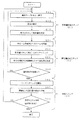
- FIGS. 7 and 8 are flowcharts of the main configuration and operation of the stereolithographic composite processing machine capable of performing the powder sintering lamination method and the cutting process. Respectively.
- the stereolithography combined processing machine 1 includes a powder layer forming means 2, a light beam irradiation means 3, and a cutting means 4, as shown in FIGS.
- the powder layer forming means 2 is means for forming a powder layer by spreading a powder such as a metal powder or a resin powder with a predetermined thickness.
- the light beam irradiation means 3 is a means for irradiating a predetermined portion of the powder layer with the light beam L.
- the cutting means 4 is a means for cutting the side surface of the laminated solidified layer, that is, the surface of the three-dimensional shaped object.
- the powder layer forming means 2 mainly comprises a powder table 25, a squeezing blade 23, a modeling table 20, and a modeling plate 21, as shown in FIG.
- the powder table 25 is a table that can be moved up and down in a powder material tank 28 whose outer periphery is surrounded by a wall 26.
- the squeezing blade 23 is a blade that can move in the horizontal direction to obtain the powder layer 22 by supplying the powder 19 on the powder table 25 onto the modeling table 20.
- the modeling table 20 is a table that can be moved up and down in a modeling tank 29 whose outer periphery is surrounded by a wall 27.
- the modeling plate 21 is a plate that is arranged on the modeling table 20 and serves as a base for a three-dimensional modeled object.
- the light beam irradiating means 3 mainly includes a light beam oscillator 30 and a galvanometer mirror 31, as shown in FIG.
- the light beam oscillator 30 is a device that emits a light beam L.
- the galvanometer mirror 31 is a means for scanning the emitted light beam L into the powder layer, that is, a scanning means for the light beam L.
- the cutting means 4 mainly comprises a milling head 40 and a drive mechanism 41 as shown in FIG.
- the milling head 40 is a cutting tool for cutting the side surface of the laminated solidified layer, that is, the surface of the three-dimensional shaped object.
- the drive mechanism 41 is means for moving the milling head 40 to a desired location to be cut.
- the operation of the stereolithography combined processing machine includes a powder layer forming step (S1), a solidified layer forming step (S2), and a cutting step (S3).
- the powder layer forming step (S1) is a step for forming the powder layer 22.
- the modeling table 20 is lowered by ⁇ t (S11) so that the level difference between the upper surface of the modeling plate 21 and the upper end surface of the modeling tank 29 becomes ⁇ t.
- the squeezing blade 23 is moved in the horizontal direction from the powder material tank 28 toward the modeling tank 29 as shown in FIG.
- the powder 19 arranged on the powder table 25 can be transferred onto the modeling plate 21 (S12), and the powder layer 22 is formed (S13).
- the powder material for forming the powder layer include “metal powder having an average particle diameter of about 5 ⁇ m to 100 ⁇ m” and “resin powder such as nylon, polypropylene, or ABS having an average particle diameter of about 30 ⁇ m to 100 ⁇ m”. . If a powder layer is formed, it will transfer to a solidified layer formation step (S2).
- the solidified layer forming step (S2) is a step of forming the solidified layer 24 by light beam irradiation.
- the light beam L is emitted from the light beam oscillator 30 (S21), and the light beam L is scanned to a predetermined location on the powder layer 22 by the galvano mirror 31 (S22).
- the powder at a predetermined location of the powder layer is sintered or melted and solidified to form the solidified layer 24 as shown in FIG. 6B (S23).
- a carbon dioxide laser, an Nd: YAG laser, a fiber laser, an ultraviolet ray, or the like may be used.
- the powder layer forming step (S1) and the solidified layer forming step (S2) are alternately repeated. Thereby, as shown in FIG.6 (c), the some solidified layer 24 is laminated
- the cutting step (S3) is a step for cutting the side surface of the laminated solidified layer 24, that is, the surface of the three-dimensional shaped object.
- the cutting step is started by driving the milling head 40 (see FIG. 6C and FIG. 7) (S31). For example, when the milling head 40 has an effective blade length of 3 mm, a cutting process of 3 mm can be performed along the height direction of the three-dimensional shaped object.
- the milling head 40 is driven. Specifically, a cutting process is performed on the side surface of the laminated solidified layer 24 while moving the milling head 40 by the drive mechanism 41 (S32).
- the manufacturing method according to one embodiment of the present invention is characterized by the light beam scanning conditions for the above-described powder sintering lamination method.
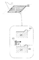
- scanning of the light beam is performed by “light beam scanning A for irradiating a portion corresponding to the contour portion of the three-dimensional shaped object” and “three-dimensional shape object inside the contour portion”.
- the portion corresponding to the inner region of the light beam is divided into a light beam scanning B ”for irradiating a light beam.
- the light beam scanning A is indicated by reference numeral “65”
- the light beam scanning B is indicated by reference numeral “75”.
- the peak power P is relatively adjusted between the light beam scanning A and the light beam scanning B.
- the peak power P A of the light beam L A for the “portion corresponding to the contour portion” is lower than the peak power P B of the light beam L B for the “portion corresponding to the inner region portion”.
- the relative adjustment of P is performed (see FIG. 1). In other words, lower than the peak power P B of the peak power P A of "portion corresponding to a contour portion""portion corresponding to the inner area part".
- the light beam scanning conditions are relatively adjusted between the light beam scanning A and the light beam scanning B.
- “bumps” that can occur during formation of the solidified layer can be reduced. More specifically, when the peak power P A for "portion corresponding to a contour portion” adjusts the peak power P to be lower than the peak power P B for "the portion corresponding to the inner area part", "contour It is possible to reduce the bulge that may occur in the “corresponding portion”. According to the manufacturing method according to one aspect of the present invention, when the light beam is scanned separately into a portion corresponding to the contour portion of the three-dimensionally shaped object and a portion corresponding to the inner region portion that is on the inner side thereof Even so, the bulge of the portion corresponding to the contour portion can be reduced.
- the manufacturing method according to one aspect of the present invention can reduce the bulge, in particular, the bulge of “the portion corresponding to the contour portion of the three-dimensional shaped object”, and as a result, the ski layer is formed when the powder layer 22 is subsequently formed. The movement of the ging blade 23 is not hindered.
- the “contour part” means a part of the outer peripheral contour that forms the outer surface part of the three-dimensional shaped object.
- the “portion corresponding to the contour portion” corresponds to the peripheral portion in the “region of the three-dimensional shaped article to be manufactured” defined by the powder layer.
- the “contour part” may be regarded as a form having a width dimension in the “peripheral part”, for example, from the outermost surface of the three-dimensional shaped object to about 0.01 mm to about 3 mm inside (horizontal inner side).
- the local region from about 0.05 mm to about 0.3 mm inside (horizontal direction inside) corresponds to the “contour” of the three-dimensional shaped object.
- the “inner region portion” in this specification means a solid portion that is inside the contour portion in the three-dimensional shaped object.
- the “portion corresponding to the internal region portion” corresponds to a portion excluding the “peripheral portion” in the “region of the three-dimensional shaped article to be manufactured” defined by the powder layer.
- the peak power P is relatively adjusted between the light beam scanning A and the light beam scanning B.
- the “peak power P A of the light beam applied to the portion that becomes the contour portion of the three-dimensional shaped object” is changed to “the peak power P of the light beam applied to the portion that becomes the inner region portion of the three-dimensional shaped object”. B ”.
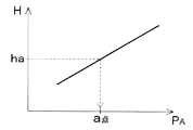
- the specific values of the light beam of the peak power P A is irradiated to the portion to be the contour of the three-dimensionally shaped object, part of the ridge height corresponding to the contour of the "peak power P A and three-dimensionally shaped object It is preferable to determine from “correlation with height H”. This will be described in detail. Under the condition that the energy density of the light beam is constant, as shown in FIG. 3, “peak power P A ” and “protrusion height H corresponding to the contour portion of the three-dimensional shaped object” are approximately proportional. May have a relationship.
- the specific value of the peak power P A can be determined from the thickness of the powder layer to be formed (that is, the gap dimension “h a ” between the squeezing blade and the shaping plate when forming the powder layer). .
- the height dimension I is smaller than the gap size between the squeezing blade and the modeling plate when forming the powder layer.
- the relative adjustment of the peak power P may be performed by relatively changing the output of the light beam between the light beam scan A and the light beam scan B. That is, the relative adjustment between the peak power P A and the peak power P B may be performed by relatively changing the output of the light beam between the light beam scanning A and the light beam scanning B. Specifically, by making the light beam output U A for the light beam scanning A lower than the light beam output U B for the light beam scanning B, the peak power P A is made higher than the peak power P B. May be lowered.
- the relative adjustment between the peak power P A and the peak power P B may be performed by relatively changing the spot diameter of the light beam between the light beam scan A and the light beam scan B. Specifically, the light of the light beam spot diameter D A for the beam scanning A, by greater than the light beam spot diameter D B for light beam scanning B, the peak power P A peak power P It may be lower than B.
- the relative adjustment of the peak power P by changing the output of the light beam or changing the spot diameter of the light beam is a relatively simple operation. In general, it is difficult to predict how much of the “bulge” of the “part corresponding to the contour of the three-dimensional shaped object” will occur. It is difficult to design the original shaped object. In this regard, the manufacturing method according to one aspect of the present invention can omit the design itself assuming such a phenomenon that is difficult to predict by “relatively simple adjustment of the light beam”.
- the light beam is scanned so that the light beam scan B is performed prior to the light beam scan A.
- the light beam scanning A it is preferable to carry out the light beam scanning A ”for the purpose.
- the energy density of the light beam may be the same between the light beam scan A and the light beam scan B.
- the "inner region portion and the" portion corresponding to a contour portion "of the lower conditions than the peak power P B of the peak power P A is” portion corresponding to the inner area part "of the” portion corresponding to a contour portion "
- the energy density of the light beam may be the same between the “corresponding portions”.
- “Aspects with the same energy density” means that the solidification density of the contour part in the obtained three-dimensional shaped object is reduced in the inner region part while reducing the bulge of the part corresponding to the contour part of the three-dimensional shaped object. Can be made identical to each other without lowering.
- the “solidification density” corresponds to the “sintering density”. Therefore, such a mode reduces the bulge of the portion corresponding to the contour portion of the three-dimensional shaped object, while the third order.
- the sintered density can be made substantially the same between the contour portion and the internal region portion of the original shaped article.
- the light beam scanning A for the “part corresponding to the contour part” of the three-dimensionally shaped object.
- the light beam may be scanned so that a plurality of annular irradiation paths are adjacent to each other along a portion corresponding to the contour portion of the three-dimensional shaped object.
- a plurality of annular irradiation paths M i 1,2,3...
- the light beams may be scanned so that they are adjacent to each other.
- the light beam scanning A may be performed so that a plurality of irradiation paths having a form that closes along the “portion corresponding to the contour portion” are adjacent to each other.
- the peak power P is lower in the “relatively located annular irradiation path light beam” than the “relatively located annular irradiation path light beam”. It is preferable to scan the light beam. For example, in the embodiment shown in FIG.
- the light beam of the linear irradiation path positioned relatively outside has a peak power P higher than “the light beam of the linear irradiation path positioned relatively inside”. It is preferable to scan the light beam so as to be low. For example, taking the mode shown in FIG. 5A as an example, “a linear irradiation path positioned relatively outside” and “a linear irradiation path positioned relatively inside” in the “part corresponding to the contour portion”. "And exist. In the mode shown in the figure, in the lateral region (“X region” in FIG.
- X region is a region whose longitudinal direction corresponds to the extending direction of the linear irradiation path.
- the peak powers for the linear irradiation paths N 1 , N 2 and N 3 are P A (N1) , P A (N2) and P A (N3) , respectively. It is preferable to carry out the light beam scanning A so that P A (N1) ⁇ P A (N2) ⁇ P A (N3) .
- the "Y region” may be implemented a light beam scanning A small peak power P A than the value of "ha” is derived from "a point” graphically shown in FIG. 3, for example ( "Y The “region” is a region whose longitudinal direction corresponds to a direction orthogonal to the extending direction of the linear irradiation path).
- the light beam scanning B of “the portion corresponding to the internal region of the three-dimensional shaped object” will be added.
- the light beam irradiation of the “portion corresponding to the inner region portion” may have a form in which a plurality of linear irradiation paths are arranged in parallel.
- so-called raster scanning may be performed in which the light beam is scanned linearly and in parallel.
- the light beam scanning A (65) shown in FIGS. 5A and 5B can also be regarded as raster scanning. Therefore, the mode shown in FIGS. 5A and 5B is a mode in which raster scanning is performed on both the portion corresponding to the internal region portion and the portion corresponding to the contour portion of the three-dimensionally shaped object. It can be said.
- the manufacturing method of the present invention is not only for the powder sintering lamination method (see FIGS. 6 and 7) that additionally performs the cutting process, but also for the powder sintering lamination method that does not perform the cutting process. It can be implemented similarly.
- First aspect (i) a step of irradiating a predetermined portion of the powder layer with a light beam to sinter or melt-solidify the powder at the predetermined portion to form a solidified layer; and (ii) on the obtained solidified layer Forming a new powder layer, irradiating a predetermined portion of the new powder layer with a light beam to form a further solidified layer, and repeating the powder layer formation and the solidified layer formation alternately to form a three-dimensional shape modeling A method for manufacturing a product, Light beam scanning A for irradiating the portion corresponding to the contour portion of the three-dimensional shaped object with the light beam scanning, and the inner region of the three-dimensional shaped object inside the contour portion The part corresponding to the part is divided into the light beam scanning B for irradiating the light beam, Said light beam to be lower than the peak power P B for the portion where the peak power P A of the light beam with respect to a portion corresponding to the
- Second aspect The method for manufacturing a three-dimensional shaped object according to the first aspect, wherein the light beam is scanned so that the light beam scan B is performed prior to the light beam scan A.
- Third aspect In the first aspect or the second aspect, in the light beam scanning A, the light beam is scanned so that a plurality of annular irradiation paths are adjacent to each other along a portion corresponding to the contour portion. A method for producing a featured three-dimensional shaped object.
- Fourth aspect In the first aspect or the second aspect, in the light beam scanning A, the light beam is scanned so that a plurality of linear irradiation paths are arranged in parallel at a portion corresponding to the contour portion. A method for producing a three-dimensional shaped object.
- the peak power P by changing the output of the light beam relatively between the light beam scan A and the light beam scan B, the peak power P A method for producing a three-dimensional shaped object, wherein the relative adjustment is performed.
- the peak power P is changed by relatively changing a spot diameter of the light beam between the light beam scan A and the light beam scan B. The method for producing a three-dimensional shaped object, wherein the relative adjustment is performed.
- Seventh aspect The three-dimensional shape according to any one of the first to sixth aspects, wherein the energy density of the light beam is the same between the light beam scan A and the light beam scan B. Manufacturing method of a model.
- Various articles can be manufactured by carrying out the manufacturing method of the three-dimensional shaped object according to one embodiment of the present invention.
- the resulting three-dimensional shaped article is a plastic injection mold, a press mold, a die-cast mold, It can be used as a mold such as a casting mold or a forging mold.
- the powder layer is an organic resin powder layer and the solidified layer is a hardened layer
- the obtained three-dimensional shaped article can be used as a resin molded product.
Landscapes
- Engineering & Computer Science (AREA)
- Chemical & Material Sciences (AREA)
- Materials Engineering (AREA)
- Manufacturing & Machinery (AREA)
- Physics & Mathematics (AREA)
- Automation & Control Theory (AREA)
- Optics & Photonics (AREA)
- Mechanical Engineering (AREA)
- Plasma & Fusion (AREA)
- Health & Medical Sciences (AREA)
- General Health & Medical Sciences (AREA)
- Toxicology (AREA)
- Powder Metallurgy (AREA)
Abstract
Description
(i)粉末層の所定箇所に光ビームを照射し、かかる所定箇所の粉末を焼結又は溶融固化させて固化層を形成する工程。
(ii)得られた固化層の上に新たな粉末層を形成し、同様に光ビームを照射して更なる固化層を形成する工程。
(i)粉末層の所定箇所に光ビームを照射してその所定箇所の粉末を焼結又は溶融固化させて固化層を形成する工程、および
(ii)得られた固化層の上に新たな粉末層を形成し、その新たな粉末層の所定箇所に光ビームを照射して更なる固化層を形成する工程
によって粉末層形成および固化層形成を交互に繰り返して行う三次元形状造形物の製造方法であって、
光ビームの走査を「三次元形状造形物の輪郭部に相当する部分を光ビーム照射するための光ビーム走査A」と「前記輪郭部よりも内側となる三次元形状造形物の内部領域部に相当する部分を光ビーム照射するための光ビーム走査B」とに分けており、
輪郭部に相当する部分に対する光ビームのピークパワーPAが内部領域部に相当する部分に対する光ビームのピークパワーPBよりも低くなるように、光ビーム走査Aと光ビーム走査Bとの間で相対的にピークパワーPを調整することを特徴とする、三次元形状造形物の製造方法が提供される。
まず、本発明の製造方法の前提となる粉末焼結積層法について説明する。粉末焼結積層法において三次元形状造形物の切削処理を付加的に行う光造形複合加工を例として挙げる。図6は、光造形複合加工のプロセス態様を模式的に示しており、図7および図8は、粉末焼結積層法と切削処理とを実施できる光造形複合加工機の主たる構成および動作のフローチャートをそれぞれ示している。
本発明の一態様に係る製造方法は、上述した粉末焼結積層法につき、光ビームの走査条件に特徴を有している。

(P:光ビームのパワー[W]、P0:ピークパワー[W]、r:集光半径(スポット径/2)[mm]、σ:標準偏差[-]、S:集光面積[mm2])
U[W]:ビーム出力
V[mm/s]:走査速度
D[mm]:スポット径
第1態様:(i)粉末層の所定箇所に光ビームを照射して該所定箇所の粉末を焼結又は溶融固化させて固化層を形成する工程、および
(ii)得られた固化層の上に新たな粉末層を形成し、該新たな粉末層の所定箇所に光ビームを照射して更なる固化層を形成する工程
によって粉末層形成および固化層形成を交互に繰り返して行う三次元形状造形物の製造方法であって、
前記光ビームの走査を、前記三次元形状造形物の輪郭部に相当する部分を光ビーム照射するための光ビーム走査Aと、該輪郭部よりも内側となる該三次元形状造形物の内部領域部に相当する部分を光ビーム照射するための光ビーム走査Bとに分けており、
前記輪郭部に相当する部分に対する前記光ビームのピークパワーPAが前記内部領域部に相当する部分に対する前記光ビームのピークパワーPBよりも低くなるように、前記光ビーム走査Aと前記光ビーム走査Bとの間で相対的にピークパワーPを調整することを特徴とする、三次元形状造形物の製造方法。
第2態様:上記第1態様において、前記光ビーム走査Aに先立って前記光ビーム走査Bが行われるように前記光ビームを走査することを特徴とする三次元形状造形物の製造方法。
第3態様:上記第1態様または第2態様において、前記光ビーム走査Aにおいて、前記輪郭部に相当する部分に沿って複数の環状照射パスが互いに隣接するように前記光ビームを走査することを特徴とする三次元形状造形物の製造方法。
第4態様:上記第1態様または第2態様において、前記光ビーム走査Aにおいて、前記輪郭部に相当する部分にて複数の直線状照射パスが並列するように前記光ビームを走査することを特徴とする三次元形状造形物の製造方法。
第5態様:上記第1態様~第4態様のいずれかにおいて、前記光ビーム走査Aと前記光ビーム走査Bとの間で相対的に前記光ビームの出力を変えることによって、前記ピークパワーPの前記相対的な調整を行うことを特徴とする三次元形状造形物の製造方法。
第6態様:上記第1態様~第5態様のいずれかにおいて、前記光ビーム走査Aと前記光ビーム走査Bとの間で相対的に前記光ビームのスポット径を変えることによって、前記ピークパワーPの前記相対的な調整を行うことを特徴とする三次元形状造形物の製造方法。
第7態様:上記第1態様~第6態様のいずれかにおいて、前記光ビーム走査Aと前記光ビーム走査Bとの間で前記光ビームのエネルギー密度を同一にすることを特徴とする三次元形状造形物の製造方法。
24 固化層
60 三次元形状造形物の輪郭部に相当する部分
65 光ビーム走査A
75 光ビーム走査B
L 光ビーム
LA “三次元形状造形物の輪郭部に相当する部分”に対する光ビーム
LB “三次元形状造形物の内部領域部に相当する部分”に対する光ビーム
PA “三次元形状造形物の輪郭部に相当する部分”に対する光ビームのピークパワー
PB “三次元形状造形物の内部領域部に相当する部分”に対する光ビームのピークパワー
M1,M2,M3 環状照射パス
N1,N2,N3(N’1,N’2,N’3) 直線状照射パス
Claims (7)
- (i)粉末層の所定箇所に光ビームを照射して該所定箇所の粉末を焼結又は溶融固化させて固化層を形成する工程、および
(ii)得られた固化層の上に新たな粉末層を形成し、該新たな粉末層の所定箇所に光ビームを照射して更なる固化層を形成する工程
によって粉末層形成および固化層形成を交互に繰り返して行う三次元形状造形物の製造方法であって、
前記光ビームの走査を、前記三次元形状造形物の輪郭部に相当する部分を光ビーム照射するための光ビーム走査Aと、該輪郭部よりも内側となる該三次元形状造形物の内部領域部に相当する部分を光ビーム照射するための光ビーム走査Bとに分けており、
前記輪郭部に相当する部分に対する前記光ビームのピークパワーPAが前記内部領域部に相当する部分に対する前記光ビームのピークパワーPBよりも低くなるように、前記光ビーム走査Aと前記光ビーム走査Bとの間で相対的にピークパワーPを調整することを特徴とする、三次元形状造形物の製造方法。 - 前記光ビーム走査Aに先立って前記光ビーム走査Bが行われるように前記光ビームを走査することを特徴とする、請求項1に記載の三次元形状造形物の製造方法。
- 前記光ビーム走査Aにおいて、前記輪郭部に相当する部分に沿って複数の環状照射パスが互いに隣接するように前記光ビームを走査することを特徴とする、請求項1に記載の三次元形状造形物の製造方法。
- 前記光ビーム走査Aにおいて、前記輪郭部に相当する部分にて複数の直線状照射パスが並列するように前記光ビームを走査することを特徴とする、請求項1に記載の三次元形状造形物の製造方法。
- 前記光ビーム走査Aと前記光ビーム走査Bとの間で相対的に前記光ビームの出力を変えることによって、前記ピークパワーPの前記相対的な調整を行うことを特徴とする、請求項1に記載の三次元形状造形物の製造方法。
- 前記光ビーム走査Aと前記光ビーム走査Bとの間で相対的に前記光ビームのスポット径を変えることによって、前記ピークパワーPの前記相対的な調整を行うことを特徴とする、請求項1に記載の三次元形状造形物の製造方法。
- 前記光ビーム走査Aと前記光ビーム走査Bとの間で前記光ビームのエネルギー密度を同一にすることを特徴とする、請求項1に記載の三次元形状造形物の製造方法。
Priority Applications (5)
| Application Number | Priority Date | Filing Date | Title |
|---|---|---|---|
| US15/123,101 US9707622B2 (en) | 2014-03-05 | 2015-03-04 | Method for manufacturing three-dimensional shaped object |
| JP2016506142A JP6414588B2 (ja) | 2014-03-05 | 2015-03-04 | 三次元形状造形物の製造方法 |
| CN201580011550.6A CN106061718B (zh) | 2014-03-05 | 2015-03-04 | 三维形状造型物的制造方法 |
| KR1020167026328A KR20160123387A (ko) | 2014-03-05 | 2015-03-04 | 3차원 형상 조형물의 제조 방법 |
| EP15758166.1A EP3115181A4 (en) | 2014-03-05 | 2015-03-04 | Method for producing three-dimensional molded article |
Applications Claiming Priority (2)
| Application Number | Priority Date | Filing Date | Title |
|---|---|---|---|
| JP2014043102 | 2014-03-05 | ||
| JP2014-043102 | 2014-03-05 |
Publications (1)
| Publication Number | Publication Date |
|---|---|
| WO2015133137A1 true WO2015133137A1 (ja) | 2015-09-11 |
Family
ID=54054952
Family Applications (1)
| Application Number | Title | Priority Date | Filing Date |
|---|---|---|---|
| PCT/JP2015/001155 Ceased WO2015133137A1 (ja) | 2014-03-05 | 2015-03-04 | 三次元形状造形物の製造方法 |
Country Status (6)
| Country | Link |
|---|---|
| US (1) | US9707622B2 (ja) |
| EP (1) | EP3115181A4 (ja) |
| JP (1) | JP6414588B2 (ja) |
| KR (1) | KR20160123387A (ja) |
| CN (1) | CN106061718B (ja) |
| WO (1) | WO2015133137A1 (ja) |
Cited By (3)
| Publication number | Priority date | Publication date | Assignee | Title |
|---|---|---|---|---|
| WO2019049981A1 (ja) * | 2017-09-08 | 2019-03-14 | 公立大学法人大阪府立大学 | 積層造形物の解析方法及び積層造形物の解析装置、並びに積層造形物の製造方法及び積層造形物の製造装置 |
| JP2021042415A (ja) * | 2019-09-10 | 2021-03-18 | 株式会社ジェイテクト | 金属付加製造装置及び金属付加製造方法 |
| WO2022038961A1 (ja) * | 2020-08-19 | 2022-02-24 | 株式会社神戸製鋼所 | 積層造形物の製造システム、積層造形物の製造方法、及び積層造形物の製造プログラム |
Families Citing this family (4)
| Publication number | Priority date | Publication date | Assignee | Title |
|---|---|---|---|---|
| JP6531954B2 (ja) | 2014-07-30 | 2019-06-19 | パナソニックIpマネジメント株式会社 | 三次元形状造形物の製造方法および三次元形状造形物 |
| WO2019141381A1 (en) * | 2018-01-22 | 2019-07-25 | SLM Solutions Group AG | Additive manufacturing apparatus and method for producing a three-dimensional work piece with multiple laser sub-beams from a spatial light modulator splitting a single laser source |
| DE102021129468A1 (de) * | 2021-11-11 | 2023-05-11 | Trumpf Laser- Und Systemtechnik Gmbh | Verfahren, Planungsvorrichtung und Computerprogrammprodukt zum Planen einer lokal selektiven Bestrahlung eines Arbeitsbereichs mit einem Energiestrahl, sowie Verfahren, Fertigungsvorrichtung und Computerprogrammprodukt zum additiven Fertigen von Bauteilen aus einem Pulvermaterial |
| CN118162632B (zh) * | 2024-03-28 | 2024-10-08 | 安世数擎(杭州)信息科技服务有限公司 | 一种定向能束高平整度粉末成形方法 |
Citations (6)
| Publication number | Priority date | Publication date | Assignee | Title |
|---|---|---|---|---|
| JPH10505799A (ja) * | 1994-05-13 | 1998-06-09 | イーオーエス ゲゼルシャフト ミット ベシュレンクテル ハフツング イレクトロ オプティカル システムズ | 3次元物体の製造方法及び装置 |
| JP2003062914A (ja) * | 2001-06-29 | 2003-03-05 | Three D Syst Inc | 三次元物体の形成方法 |
| JP2004130793A (ja) * | 2002-09-30 | 2004-04-30 | Eos Gmbh Electro Optical Systems | 三次元オブジェクトを一層毎に製造する装置及びその方法 |
| JP2011021218A (ja) * | 2009-07-14 | 2011-02-03 | Kinki Univ | 積層造形用粉末材料及び粉末積層造形法 |
| JP2013163829A (ja) * | 2012-02-09 | 2013-08-22 | Panasonic Corp | 三次元形状造形物の製造方法および三次元形状造形物 |
| WO2013132840A1 (ja) * | 2012-03-09 | 2013-09-12 | パナソニック株式会社 | 三次元形状造形物の製造方法 |
Family Cites Families (10)
| Publication number | Priority date | Publication date | Assignee | Title |
|---|---|---|---|---|
| EP0542729B1 (en) | 1986-10-17 | 1996-05-22 | Board Of Regents, The University Of Texas System | Method and apparatus for producing parts by selective sintering |
| US5014207A (en) | 1989-04-21 | 1991-05-07 | E. I. Du Pont De Nemours And Company | Solid imaging system |
| DE4309524C2 (de) | 1993-03-24 | 1998-05-20 | Eos Electro Optical Syst | Verfahren zum Herstellen eines dreidimensionalen Objekts |
| JPH115254A (ja) | 1997-04-25 | 1999-01-12 | Toyota Motor Corp | 積層造形方法 |
| JP3446618B2 (ja) | 1998-08-26 | 2003-09-16 | 松下電工株式会社 | 金属粉末焼結部品の表面仕上げ方法 |
| JP4857103B2 (ja) | 2006-12-25 | 2012-01-18 | 株式会社アスペクト | 粉末焼結積層造形装置及び粉末焼結積層造形方法 |
| EP2335848B1 (de) * | 2009-12-04 | 2014-08-20 | SLM Solutions GmbH | Optische Bestrahlungseinheit für eine Anlage zur Herstellung von Werkstücken durch Bestrahlen von Pulverschichten mit Laserstrahlung |
| JP5612530B2 (ja) | 2011-04-19 | 2014-10-22 | パナソニック株式会社 | 三次元形状造形物の製造方法 |
| JP5877471B2 (ja) * | 2011-05-23 | 2016-03-08 | パナソニックIpマネジメント株式会社 | 三次元形状造形物の製造方法 |
| DE112013003448T5 (de) | 2012-07-09 | 2015-04-16 | Panasonic Intellectual Property Management Co., Ltd. | Verfahren zum Fertigen eines dreidimensionalen Formgegenstands |
-
2015
- 2015-03-04 EP EP15758166.1A patent/EP3115181A4/en not_active Withdrawn
- 2015-03-04 CN CN201580011550.6A patent/CN106061718B/zh not_active Expired - Fee Related
- 2015-03-04 WO PCT/JP2015/001155 patent/WO2015133137A1/ja not_active Ceased
- 2015-03-04 US US15/123,101 patent/US9707622B2/en not_active Expired - Fee Related
- 2015-03-04 KR KR1020167026328A patent/KR20160123387A/ko not_active Ceased
- 2015-03-04 JP JP2016506142A patent/JP6414588B2/ja active Active
Patent Citations (6)
| Publication number | Priority date | Publication date | Assignee | Title |
|---|---|---|---|---|
| JPH10505799A (ja) * | 1994-05-13 | 1998-06-09 | イーオーエス ゲゼルシャフト ミット ベシュレンクテル ハフツング イレクトロ オプティカル システムズ | 3次元物体の製造方法及び装置 |
| JP2003062914A (ja) * | 2001-06-29 | 2003-03-05 | Three D Syst Inc | 三次元物体の形成方法 |
| JP2004130793A (ja) * | 2002-09-30 | 2004-04-30 | Eos Gmbh Electro Optical Systems | 三次元オブジェクトを一層毎に製造する装置及びその方法 |
| JP2011021218A (ja) * | 2009-07-14 | 2011-02-03 | Kinki Univ | 積層造形用粉末材料及び粉末積層造形法 |
| JP2013163829A (ja) * | 2012-02-09 | 2013-08-22 | Panasonic Corp | 三次元形状造形物の製造方法および三次元形状造形物 |
| WO2013132840A1 (ja) * | 2012-03-09 | 2013-09-12 | パナソニック株式会社 | 三次元形状造形物の製造方法 |
Non-Patent Citations (1)
| Title |
|---|
| See also references of EP3115181A4 * |
Cited By (5)
| Publication number | Priority date | Publication date | Assignee | Title |
|---|---|---|---|---|
| WO2019049981A1 (ja) * | 2017-09-08 | 2019-03-14 | 公立大学法人大阪府立大学 | 積層造形物の解析方法及び積層造形物の解析装置、並びに積層造形物の製造方法及び積層造形物の製造装置 |
| US12343818B2 (en) | 2017-09-08 | 2025-07-01 | University Public Corporation Osaka | Method and apparatus for analyzing additively manufactured object, and method and apparatus for additively manufacturing an object |
| JP2021042415A (ja) * | 2019-09-10 | 2021-03-18 | 株式会社ジェイテクト | 金属付加製造装置及び金属付加製造方法 |
| JP7388067B2 (ja) | 2019-09-10 | 2023-11-29 | 株式会社ジェイテクト | 金属付加製造装置及び金属付加製造方法 |
| WO2022038961A1 (ja) * | 2020-08-19 | 2022-02-24 | 株式会社神戸製鋼所 | 積層造形物の製造システム、積層造形物の製造方法、及び積層造形物の製造プログラム |
Also Published As
| Publication number | Publication date |
|---|---|
| US9707622B2 (en) | 2017-07-18 |
| EP3115181A1 (en) | 2017-01-11 |
| KR20160123387A (ko) | 2016-10-25 |
| JP6414588B2 (ja) | 2018-10-31 |
| EP3115181A4 (en) | 2017-03-08 |
| CN106061718B (zh) | 2018-01-02 |
| CN106061718A (zh) | 2016-10-26 |
| JPWO2015133137A1 (ja) | 2017-04-06 |
| US20170072464A1 (en) | 2017-03-16 |
Similar Documents
| Publication | Publication Date | Title |
|---|---|---|
| JP6443698B2 (ja) | 三次元形状造形物の製造方法 | |
| JP6414588B2 (ja) | 三次元形状造形物の製造方法 | |
| JP5599957B2 (ja) | 三次元形状造形物の製造方法 | |
| CN104428084B (zh) | 三维形状造型物的制造方法 | |
| JP5776004B2 (ja) | 三次元形状造形物の製造方法および三次元形状造形物 | |
| JP5539347B2 (ja) | 三次元形状造形物の製造方法およびそれから得られる三次元形状造形物 | |
| JPWO2016017155A1 (ja) | 三次元形状造形物の製造方法および三次元形状造形物 | |
| CN107848212B (zh) | 三维形状造型物的制造方法 | |
| WO2017022144A1 (ja) | 三次元形状造形物の製造方法および三次元形状造形物 | |
| WO2017022145A1 (ja) | 三次元形状造形物の製造方法および三次元形状造形物 | |
| JPWO2017221912A1 (ja) | 三次元形状造形物の製造方法 | |
| JP2017226882A (ja) | 三次元形状造形物の製造方法 | |
| WO2019151540A1 (ja) | 三次元形状造形物の製造方法 | |
| JPWO2017154971A1 (ja) | 三次元形状造形物の製造方法 | |
| WO2017221712A1 (ja) | 三次元形状造形物の製造方法 |
Legal Events
| Date | Code | Title | Description |
|---|---|---|---|
| 121 | Ep: the epo has been informed by wipo that ep was designated in this application |
Ref document number: 15758166 Country of ref document: EP Kind code of ref document: A1 |
|
| WWE | Wipo information: entry into national phase |
Ref document number: 15123101 Country of ref document: US |
|
| ENP | Entry into the national phase |
Ref document number: 2016506142 Country of ref document: JP Kind code of ref document: A |
|
| NENP | Non-entry into the national phase |
Ref country code: DE |
|
| ENP | Entry into the national phase |
Ref document number: 20167026328 Country of ref document: KR Kind code of ref document: A |
|
| REEP | Request for entry into the european phase |
Ref document number: 2015758166 Country of ref document: EP |
|
| WWE | Wipo information: entry into national phase |
Ref document number: 2015758166 Country of ref document: EP |