WO2015133367A1 - 作業機械の周辺監視装置 - Google Patents
作業機械の周辺監視装置 Download PDFInfo
- Publication number
- WO2015133367A1 WO2015133367A1 PCT/JP2015/055668 JP2015055668W WO2015133367A1 WO 2015133367 A1 WO2015133367 A1 WO 2015133367A1 JP 2015055668 W JP2015055668 W JP 2015055668W WO 2015133367 A1 WO2015133367 A1 WO 2015133367A1
- Authority
- WO
- WIPO (PCT)
- Prior art keywords
- image
- area
- camera
- work machine
- display
- Prior art date
- Legal status (The legal status is an assumption and is not a legal conclusion. Google has not performed a legal analysis and makes no representation as to the accuracy of the status listed.)
- Ceased
Links
Images


Classifications
-
- E—FIXED CONSTRUCTIONS
- E02—HYDRAULIC ENGINEERING; FOUNDATIONS; SOIL SHIFTING
- E02F—DREDGING; SOIL-SHIFTING
- E02F9/00—Component parts of dredgers or soil-shifting machines, not restricted to one of the kinds covered by groups E02F3/00 - E02F7/00
- E02F9/26—Indicating devices
- E02F9/261—Surveying the work-site to be treated
-
- G—PHYSICS
- G06—COMPUTING OR CALCULATING; COUNTING
- G06T—IMAGE DATA PROCESSING OR GENERATION, IN GENERAL
- G06T11/00—Two-dimensional [2D] image generation
- G06T11/60—Creating or editing images; Combining images with text
-
- G—PHYSICS
- G06—COMPUTING OR CALCULATING; COUNTING
- G06T—IMAGE DATA PROCESSING OR GENERATION, IN GENERAL
- G06T3/00—Geometric image transformations in the plane of the image
- G06T3/40—Scaling of whole images or parts thereof, e.g. expanding or contracting
- G06T3/4038—Image mosaicing, e.g. composing plane images from plane sub-images
-
- G—PHYSICS
- G06—COMPUTING OR CALCULATING; COUNTING
- G06T—IMAGE DATA PROCESSING OR GENERATION, IN GENERAL
- G06T7/00—Image analysis
- G06T7/0002—Inspection of images, e.g. flaw detection
- G06T7/0004—Industrial image inspection
-
- H—ELECTRICITY
- H04—ELECTRIC COMMUNICATION TECHNIQUE
- H04N—PICTORIAL COMMUNICATION, e.g. TELEVISION
- H04N23/00—Cameras or camera modules comprising electronic image sensors; Control thereof
- H04N23/60—Control of cameras or camera modules
- H04N23/698—Control of cameras or camera modules for achieving an enlarged field of view, e.g. panoramic image capture
-
- H—ELECTRICITY
- H04—ELECTRIC COMMUNICATION TECHNIQUE
- H04N—PICTORIAL COMMUNICATION, e.g. TELEVISION
- H04N23/00—Cameras or camera modules comprising electronic image sensors; Control thereof
- H04N23/90—Arrangement of cameras or camera modules, e.g. multiple cameras in TV studios or sports stadiums
-
- G—PHYSICS
- G06—COMPUTING OR CALCULATING; COUNTING
- G06T—IMAGE DATA PROCESSING OR GENERATION, IN GENERAL
- G06T2207/00—Indexing scheme for image analysis or image enhancement
- G06T2207/30—Subject of image; Context of image processing
- G06T2207/30248—Vehicle exterior or interior
- G06T2207/30252—Vehicle exterior; Vicinity of vehicle
Definitions
- the present invention relates to a periphery monitoring device for a work machine that synthesizes a bird's-eye view image from a plurality of images captured by a plurality of cameras mounted on the work machine and performs periphery monitoring using the bird's-eye view image.
- each of images captured by a plurality of cameras that capture the periphery of a work machine is converted into a bird's-eye view image, and adjacent images of the bird's-eye view image are joined in a lattice pattern, and an object having a height that disappears at the joint surface
- An operation support system is known that uses an image generation device that prevents the disappearance and has a grid shape that applies the same color illusion, so that the difference in brightness is not noticeable (see, for example, Patent Document 1).
- the image of the three-dimensional object becomes an image that falls down in the imaging direction of the camera.
- a composite image is displayed as described in Patent Document 1
- the direction in which the image falls is different for each camera
- two fallen images are displayed even when only one three-dimensional object exists. Therefore, it looks as if there are two objects.
- the information amount (number of pixels) of the captured object is reduced by half or reduced, resulting in an image in which the object is transparent. For these reasons, there is a problem that it is difficult for the driver to determine the monitoring target.
- the work machine periphery monitoring device converts a plurality of image capturing devices that capture images around the work machine, and each captured image of the plurality of image capturing devices into an upper viewpoint image.
- An overhead image generation unit that generates an overhead image around the work machine, and a display unit that displays the overhead image in the overhead image display area.
- the overhead image generation unit includes first imaging included in a plurality of imaging devices.
- the present invention it is possible to provide a periphery monitoring device that can narrow the composite image display area in the overlap area as compared with the conventional area and has excellent visibility for easily monitoring the surrounding situation.
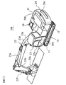
- FIG. 1 is a diagram showing a work machine (hydraulic excavator 100) on which a periphery monitoring device according to the present invention is mounted.
- FIG. 2 is a block diagram showing a configuration of the periphery monitoring device 10 mounted on the hydraulic excavator 100.
- FIG. 3 is a diagram showing a shootable area of each camera 30a, 30b, 30c provided in the vehicle body 20.
- FIG. 4 is a diagram for explaining the conversion process of the upper viewpoint image in the composite image generation unit 210.
- FIG. 5 is a diagram for explaining the cutting of the display images e1 to e3.
- FIG. 6 is a diagram showing display images e1 to e3 and overlapping areas c0 and c1 in the overhead image 300.
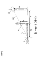
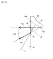
- FIG. 7 is a diagram for explaining the collapse length N.
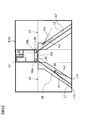
- FIG. 8 is a diagram for explaining the area setting lines L1 and L2 and the disappearance of the image.
- FIG. 9 is a diagram showing the composite display areas b6 and b7 in the overlapping areas c0 and c1.
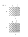
- FIG. 10 is a diagram for explaining a display form (drawing technique) in the combined display areas b6 and b7.
- FIG. 11 is a diagram showing the fallen images Pa1 and Pc1 in the composite display area b6.
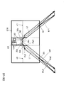
- FIG. 12 is a diagram illustrating a method for setting the composite display area b6.
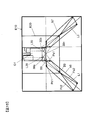
- FIG. 13 is a diagram for explaining a method of setting a composite display area for the blind spot z0.
- FIG. 14 is a diagram for explaining a display area in the periphery monitoring monitor 220.
- FIG. 15 is a diagram illustrating the composite display areas b6 and b7 when the monitoring range E20 is set.
- FIG. 16 is a perspective view schematically showing the dump truck 2 and a range displayed by the periphery monitoring device.
- FIG. 17 is a view showing an overhead image 300 displayed on the periphery monitoring monitor 220.
- FIG. 18 is a diagram illustrating an example of a region setting line in the modified example.
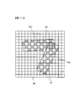
- FIG. 19 is a diagram showing the composite display area b9 set corresponding to the blind spot z3.
- FIG. 20 is a diagram illustrating composite display areas b9, b10, b11, and b12 in the modification.
- FIG. 21 is a diagram showing each display area in the periphery monitoring monitor 220.
- FIG. 22 is a diagram illustrating an upper viewpoint image (overhead image).
- FIG. 1 is a diagram showing a working machine on which a periphery monitoring device according to the present invention is mounted, and is an overall perspective view of a hydraulic excavator 100.
- the excavator 100 is mainly composed of a lower traveling body 13 and an upper revolving body 20 that is provided on the lower traveling body 13 so as to be rotatable.
- the lower traveling body 13 has a pair of crawlers 11 and 11 positioned parallel to each other on a traveling body frame (not shown), and each of the crawlers 11 and 11 has a hydraulic pressure for traveling by driving a crawler belt.
- a drive type traveling motor 12 is provided.
- the upper swing body 20 includes an engine room 21 in which various devices such as an engine, a battery, and a fuel tank installed on a swing body frame (not shown) are accommodated, and a cab 22 provided on the front left side of the engine room 21. And a front work machine 23 extending forward from the right side of the cab 22 and a counterweight 24 provided at the rear of the engine room 21 to balance the weight of the front work machine 23. .
- the driver's cab 22 is provided with a peripheral monitoring monitor, which will be described later, in addition to an operation lever and instruments for operating the front work machine 23 in a cabin 22a on which the operator is boarded.
- the front work machine 23 includes a boom 23a extending forward from the revolving structure frame side, an arm 23b swingably provided at the tip of the boom 23a, and a bucket 23c swingably provided at the tip of the arm 23b. And is composed mainly of.
- the boom 23a, the arm 23b, and the bucket 23c are operated by a boom cylinder 23d, an arm cylinder 23e, and a bucket cylinder 23f that extend and contract by hydraulic pressure, respectively.
- Three cameras 30a, 30b, and 30c for continuously photographing each direction are installed on both sides of the engine chamber 21 and the upper portion of the counterweight 24.
- the camera 30a continuously captures an area on the left side of the upper swing body 20 so as to look down at an angle of view of 180 °.
- the camera 30b continuously captures an area on the right side of the upper swing body 20 so as to look down at an angle of view of 180 °.
- the camera 30c continuously shoots an area behind the upper swing body 20 so as to look down at an angle of view of 180 °.
- the cameras 30a, 30b, and 30c are composed of, for example, a wide-angle video camera equipped with an imaging element such as a CCD or CMOS excellent in durability and weather resistance and a wide-angle lens.
- an imaging element such as a CCD or CMOS excellent in durability and weather resistance and a wide-angle lens.
- each part of the upper swing body 20 in which these cameras 30a, 30b, and 30c are installed (mounted) is collectively referred to as a vehicle body 20.
- FIG. 2 is a block diagram showing the configuration of the periphery monitoring device 10 mounted on the excavator 100.
- the periphery monitoring device 10 mainly includes a controller 200, a camera 30a, a camera 30b, a camera 30c, and a periphery monitoring monitor 220.
- the controller 200 has a composite image generation unit 210. Each image (original image) captured by each camera 30 a, 30 b, 30 c is input to the composite image generation unit 210 of the controller 200.
- the composite image generation unit 210 is configured by an image processing LSI (hardware) including a CPU, RAM, ROM, input / output interface, etc. (not shown), and various data stored in advance in the ROM or the like and a dedicated image processing program For example, the CPU realizes the function of the composite image generation unit 210.
- image processing LSI hardware
- the CPU realizes the function of the composite image generation unit 210.
- the composite image generation unit 210 creates an upper viewpoint image from a plurality (three) of original images taken by the cameras 30a, 30b, and 30c, for example, in units of 30 frames / second, and creates the upper viewpoint image (moving image). Is output. Specifically, when composite signals such as NTSC of the original image are input from the cameras 30a, 30b, and 30c, the composite image generation unit 210 performs A / D conversion of the composite signals to RGB signals. After decoding, each is stored in a dedicated frame memory. Then, after performing lens distortion correction processing, each original image is converted into an upper viewpoint image with the viewpoint moved upward by known image conversion processing such as planar projection conversion processing using a homography matrix and projection processing in a three-dimensional space. To process.
- image conversion processing such as planar projection conversion processing using a homography matrix and projection processing in a three-dimensional space.
- FIG. 3 is a view showing a shootable area of each of the cameras 30a, 30b, and 30c provided on the vehicle body 20, and is a view of the vehicle body 20 and its surrounding area as viewed from above the vehicle body 20.
- a rectangular area E1 on the left side of the vehicle body is an imageable area of the camera 30a.
- a rectangular area E2 on the right side of the vehicle body is an imageable area of the camera 30b.
- a rectangular area E3 at the rear of the vehicle body is an imageable area of the camera 30c.
- the rear end region of the rectangular area E1 and the left end region of the rectangular area E3 overlap, and this overlapping region is photographed by the camera 30a and the camera 30c. Further, the rear end region of the rectangular area E2 and the right end region of the rectangular area E3 overlap, and this overlapping region is photographed by the camera 30b and the camera 30c.
- FIG. 4 is a diagram for explaining the conversion process of the upper viewpoint image in the composite image generation unit 210.
- FIG. 4A shows an example of the original image 31 of the rectangular areas E1, E2, and E3 taken by the cameras 30a, 30b, and 30c.
- Each camera 30a, 30b, 30c shoots with a wide-angle lens whose left and right angle of view is about 180 °, so that the captured original image 31 is generally enlarged at the center and reduced at the periphery as shown by the grid lines 32. Is distorted.
- the composite image generation unit 210 performs lens distortion correction processing on the original image 31.
- FIG. 4B shows a corrected image 33 after the lens distortion correction process.
- the corrected image 33 after the correction processing is corrected to a shape according to the perspective method based on the viewpoints of the cameras 30a, 30b, and 30c, as indicated by vertical and horizontal virtual coordinate lines 34 on the ground (road surface).
- This lens distortion correction processing is described, for example, in a dedicated pixel conversion table stored in advance in a memory, that is, the correspondence between the address of each pixel constituting the image before conversion and the address of each pixel after conversion. This is performed by pixel coordinate conversion using a pixel conversion table.
- the composite image generation unit 210 performs a viewpoint conversion process for moving the viewpoint to the upper side of the vehicle body, after the correction image 33 after the lens distortion correction process.
- FIG. 4C illustrates the upper viewpoint image 35 after the viewpoint conversion process.
- the virtual coordinate line 34 in the corrected image 33 in FIG. 4B is converted into a virtual orthogonal coordinate line 36 that is orthogonal to the grid.
- This viewpoint conversion processing is also performed by pixel coordinate conversion using a dedicated pixel conversion table (conversion table for viewpoint conversion processing) stored in advance in a memory.
- FIG. 22 is a diagram illustrating an upper viewpoint image (overhead image).
- Viewpoint conversion technology is known that performs image processing on images captured by cameras provided around the work machine and obtains images in which the viewpoint position is virtually changed to the upper viewpoint. Thus, the correspondence between the real camera image and the virtual camera image is taken. If the virtual viewpoints of videos taken by multiple cameras using the viewpoint conversion technology are the same position, when the multiple videos are displayed side by side, they are displayed as if they were shot from a single camera from the same viewpoint. Is easy to understand the displayed image.
- the composite image generation unit 210 cuts out images to be actually displayed from the created upper viewpoint images 35, and combines the three cut out images to obtain a surrounding bird's-eye view image centered on the vehicle body 20 ( Video).
- a rectangular area “e” surrounded by a broken line in FIG. 4C indicates a cut-out area in the upper viewpoint image 35.
- the composite image generation unit 210 cuts out the display images e1 to e3 from the three upper viewpoint images 35L, 35R, and 35B corresponding to the rectangular areas E1, E2, and E3. Then, the composite image generation unit 210 connects the display images e1 to e3 around the image G1 corresponding to the vehicle body 20 in a ring shape to create one continuous overhead image 300 as shown in FIG. Output image data to frame memory.
- an area c0 indicated by hatching indicates an overlapping area between the display image e1 and the display image e3.
- a hatched area c1 indicates an overlapping area between the display image e2 and the display image e3.
- a gap is shown between the frame showing the display image e3 and the frame showing the overlapping areas c0 and c1 for easy understanding. However, such a gap does not actually occur.
- the overlapping area c0 there are a display image e1 based on the image captured by the camera 30a and a display image e3 based on the image captured by the camera 30c.
- the overlapping area c1 there are a display image e2 based on the image captured by the camera 30b and a display image e3 based on the image captured by the camera 30c.
- the height (mounting height) of the camera 30 (30a, 30b, 30c) mounted on the vehicle body 20 is H
- the height of the monitoring target is h.
- the monitoring target height h is set mainly depending on what is to be monitored. For example, when a person, a vehicle, or the like is a main monitoring target, a person having a height of 1.7 m is assumed, and the monitoring target height h is set to 1.5 m so that the height of the person's chest can be displayed. .
- n is the distance from the camera 30 to the monitoring target.
- Point A is a point where the straight line L10 and the ground intersect.
- the straight line L10 is a straight line connecting the center of the camera 30 (intersection of the image sensor and the optical axis) and the chest of a three-dimensional object (person) having a monitoring target height h.
- the upper viewpoint image of the three-dimensional object (person) P0 captured by the camera 30 is converted, the upper viewpoint image of the three-dimensional object P0 is displayed as an image P1. This is an image as if the three-dimensional object P0 having a height N fell on the ground.
- the point A is referred to as the falling position of the three-dimensional object P0, and the distance N from the position of the three-dimensional object P0 (position on the ground) to the point A is referred to as the falling length.
- the image P1 displayed on the display screen is referred to as a fallen image.
- FIG. 8 to 15 are diagrams illustrating a method for setting a double image display area (hereinafter referred to as a composite display area) in the present embodiment.
- a composite display area a double image display area
- area setting lines L1 and L2 for setting a composite display area are set in a display area E10 in which the overhead image 300 is displayed.
- the overlapping area c0 is bisected by the area setting line L1
- the overlapping area c1 is bisected by the area setting line L2.
- the area setting line L1 is a vertical bisector of a line segment L20 connecting the camera 30a and the camera 30c
- the area setting line L2 is a vertical line segment L30 connecting the camera 30b and the camera 30c.
- a bisector Since the area setting line L1 is equidistant from the cameras 30a and 30c, the image by the camera 30a is larger than the image by the camera 30c in the overlapping area c0 on the camera 30a side than the area setting line L1, and the camera is larger than the area setting line L1. In the overlapping area c0 on the 30c side, the image by the camera 30c is larger than the image by the camera 30a.
- the region setting lines L1 and L2 are not limited to the above-mentioned vertical bisector, and for example, in the case of the region setting line L1, it may be a straight line that intersects the line segment L20 connecting the camera 30a and the camera 30c. In the case of the area setting line L2, it may be a straight line that intersects with the line segment L30 connecting the camera 30b and the camera 30c. Strictly speaking, the line segment connecting the camera 30a and the camera 30c indicates a line segment connecting the intersections of the optical axes of the cameras 30a and 30c and the image pickup devices, but a line connecting the camera 30a and the camera 30c. If it is minutes, do not stick to this.
- the area setting line L1 is a boundary line that divides the monitoring area by the camera 30a and the monitoring area by the camera 30c
- the area setting line L2 is the monitoring area by the camera 30b. Is a boundary line that separates the monitoring area by the camera 30c and a composite display area as will be described later is not provided.
- the area z0 is an area closer to the camera 30a than the area setting line L1, but the area z0 has only a photographed image by the camera 30c and is a blind spot area that cannot be photographed by the camera 30a.
- the area z1 is an area closer to the camera 30b than the area setting line L2, but the area z1 is only a captured image by the camera 30c and is a blind spot area that cannot be captured by the camera 30b.
- the regions z0 and z1 are referred to as blind spots z0 and z1.
- a display image e1 based on the image taken by the camera 30a is displayed in the display area E11 (excluding the blind spot z0) above the area setting line L1. Further, a display image e2 based on an image photographed by the camera 30b is displayed in the display region E21 (excluding the blind spot z1) above the region setting line L2. A display image e3 based on the image taken by the camera 30c is displayed in the display area E31 between the area setting line L1 and the area setting line L2.
- the falling image of the three-dimensional object displayed as the upper viewpoint image becomes an image with the symbol Pa2.
- the fallen image Pa2 is displayed so as to fall along a straight line L11 connecting the camera 30a and the three-dimensional object.
- the display image e1 and the display image e3 exist in the overlapping region c0, and the fallen image Pa1 and the fallen image Pc1 exist for the three-dimensional object at the position B2.
- the area setting line L1 is set, the display image e1 is displayed in the display area E11, and the display area is divided so that the display image e3 is displayed in the display area E31, the display area E11 and the display area E31 are displayed.
- the composite display areas b6 and b7 as shown in FIG. 9 are provided in a part of the overlapping areas c0 and c1.
- both the display image e1 and the display image e3 are displayed in a predetermined display form.
- both fallen images Pa1 and Pc1 are displayed in the composite display area b6.
- the fallen image Pa1 falls along a straight line L12 connecting the camera 30a and the position B2
- the fallen image Pc1 falls along a straight line L13 connecting the camera 30c and the position B2.
- both the display image e2 and the display image e3 are displayed in a predetermined display form.
- FIG. 10 shows an example of the display form (drawing technique) of the composite display area, and two types of display images are arranged in a checkered pattern.
- FIG. 10A shows a composite display image in the composite display area b6, in which the display image e1 and the display image e3 are arranged in a checkered pattern.
- FIG. 10B shows a composite display image in the composite display area b7, where the display image e2 and the display image e3 are arranged in a checkered pattern.
- the size of the grid arranged in the checkered pattern can be arbitrarily set in pixel units.
- the drawing technique shown in FIG. 10 is an example.
- Various drawing techniques for the composite display area are known, and any drawing technique can be applied.
- they may be arranged in stripes, or the alpha blend process may be performed by setting the transmittance (alpha value) between overlapping pixels. That is, in the composite display area, a composite image generated by combining the image signals output from the two cameras is displayed.
- FIG. 11 shows the fallen images Pa1 and Pc1 in the composite display area b6 shown in FIG. 10 (a).
- the broken lines represent areas where the fallen images Pa1 and Pc1 are displayed and are not displayed on the actual display image.
- FIG. 11 only the display image e1 displaying the fallen image Pa1 and the display image e3 displaying the fallen image Pc1 are shown so that the fallen images Pa1 and Pc1 are easy to understand, and the display of the background image is omitted. Yes.
- B4 and B5 be the intersections of the region setting line L1 that bisects the overlapping region c0 and the overlapping region c0.
- B4 and B5 be the intersections of the region setting line L1 that bisects the overlapping region c0 and the overlapping region c0.
- B4 and B5 be the intersections of the region setting line L1 that bisects the overlapping region c0 and the overlapping region c0.
- B4 and B5 be the intersections of the region setting line L1 that bisects the overlapping region c0 and the overlapping region c0.
- the fall length N of the fallen image Pa2 (based on the image captured by the camera 30a) and the fallen image Pc2 (based on the image captured by the camera 30c) when the virtual monitoring target is arranged at the position of the intersection B5 is calculated.
- the virtual monitoring target is a three-dimensional object having a predetermined height set in advance.
- the three-dimensional object having the height of 1.5 m described above is set as the virtual monitoring target.
- this height (1.5 m) is referred to as a reference monitoring height.
- the fallen images Pa1, Pa2, Pc1, and Pc2 are displayed by arrows, and the tip of the arrow indicates the chest of the virtual monitoring target (the apex of the reference monitoring height).
- the intersection B4, the tip of the arrow Pc1, the tip of the arrow Pc2, the tip of the arrow Pa2, the tip of the arrow Pa1, and the intersection B4 are connected by line segments in this order, and the area surrounded by these line segments is combined display area b61 (composite) A part of the display area b6).
- the composite display area b61 corresponds to an area where virtual monitoring targets are arranged on the area setting line L1 from the intersection B4 to the intersection B5 and their fallen images are displayed.
- intersections B6 and B7 between the overlapping area c1 and the area setting line L2 are obtained, and the combined display area b71 (a part of the combined display area b7) is set in the same procedure.
- the area of the blind spot z0 is an area that cannot be captured by the camera 30a
- the area of the blind spot z1 is an area that cannot be captured by the camera 30b. Therefore, a composite display area is set for each of the blind spots z0 and z1.
- a composite display area b6 shown in FIG. 9 is obtained by adding a composite display area related to the dead angle z0 to the above-described composite display area b61.
- the composite display area b7 shown in FIG. 9 is obtained by adding a composite display area related to the blind spot z1 to the above-described composite display area b71.
- FIG. 13 is a diagram showing a method for setting the composite display area for the blind spot z0. Since the blind spot z0 is an area that can be captured only by the camera 30c, a case where a virtual monitoring target is arranged at the boundary between the blind spot z0 and the overlapping area c0 is considered, and a fallen image of the virtual monitoring target based on the captured image of the camera 30c is considered. In the example shown in FIG. 13, the virtual monitoring target is arranged at a position B8 closest to the vehicle body 20 (shown by the image G1) and a point B4 farthest from the vehicle body 20 within the boundary between the blind spot z0 and the overlapping region c0. To do.
- the arrow Pc1 is a fall image of the virtual monitoring target arranged at the position B8, and the arrow Pc2 is a fall image of the virtual monitoring target arranged at the position B4.
- a region formed by connecting the position B8, the tip of the arrow Pc1, the tip of the arrow Pc2, the position B4, and the position B8 in this order is defined as a composite display region b62 for the blind spot z0. All the chests of the virtual monitoring target located at the blind spot z0 are included in this composite display area b62.
- the composite display area for the blind spot z1 can be set in the same procedure as the composite display area b62.
- FIG. 14 is a diagram for explaining a display area in the periphery monitoring monitor 220.
- a display area S1 that displays an upper viewpoint image based on an image captured by the camera 30a
- a display area S2 that displays an upper viewpoint image based on an image captured by the camera 30b
- a display area S3 in which an upper viewpoint image based on an image photographed by the camera 30c is displayed and composite display areas b6 and b7 are provided. Note that the area setting lines L1 and L2 indicated by broken lines are not displayed.
- a predetermined range around the vehicle body 20 may be set as a special monitoring range, and monitoring may be performed so that a person or the like does not enter the monitoring range carelessly.
- a composite display area that takes the monitoring range into consideration is set. Note that the combined display areas b6 and b7 shown in FIG. 9 are conceived when the monitoring range is the entire display area E10.
- FIG. 15 shows the composite display areas b6 and b7 when the area setting lines L1 and L2 are set so as to pass through the left corner and the right corner of the image G1, and the above-described monitoring range is set around the image G1.
- E20 is the boundary of the monitoring range.
- the monitoring range is within 3.0 m from the vehicle body 20 (image G1).
- virtual monitoring targets are set at an intersection B8 (upper right corner of the overlapping area c0) between the area setting line L1 and the overlapping area c0 and an intersection B9 between the area setting line L1 and the monitoring range E20. Deploy.
- the fallen image Pa1 (falling position) based on the captured image of the camera 30a and the fallen image Pc1 (falling position) based on the captured image of the camera 30c are calculated for the virtual monitoring target arranged at the intersection B8.
- a fallen image Pa2 (falling position) based on a photographed image of the camera 30a and a fallen image Pc2 (falling position) based on a photographed image of the camera 30c are calculated for the virtual monitoring target arranged at the intersection B9.
- the fallen image is indicated by an arrow.
- An area formed by connecting the intersection point B8, the tip end of the arrow Pc1, the tip end of the arrow Pc2, the tip end of the arrow Pa2, the tip end of the arrow a1, and the intersection point B8 in this order is a composite display area b6.
- the composite display area b7 related to the area setting line L2 can also be set in the same procedure as in the case of the composite display area b6.
- FIG. 16 to 21 are diagrams for explaining a case where the present invention is applied to the periphery monitoring device of the dump truck 2.
- FIG. 16 and 17 are diagrams for explaining the camera mounting position and the display range (the range monitored by the camera).
- FIG. 16 is a perspective view schematically showing the dump truck 2 and the range displayed by the periphery monitoring device.
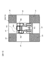
- FIG. 17 is a view showing an overhead image 300 displayed on the periphery monitoring monitor 220.
- the dump truck 2 is equipped with four cameras 50a to 50d. Specifically, a camera 50d that captures the vehicle front periphery, a camera 50a that captures the vehicle left periphery, a camera 50b that captures the vehicle right periphery, and a camera 50c that captures the vehicle periphery are provided.
- the portion of the region R1 is displayed on the periphery monitoring monitor 220 as the display image e1.
- the region R2 in the image captured by the camera 50b is the display image e2
- the region R3 in the image captured by the camera 50c is the display image e3, which is captured by the camera 50d.
- the region R4 in the obtained image is set as a display image e4.
- FIG. 17 is a view showing an overhead image 300 displayed on the periphery monitoring monitor 220.
- An image G2 representing the dump truck 2 is displayed on the periphery monitoring monitor, and display images e1 to e4 are arranged around the image G2.
- c2 is an overlapping area between the display image e1 and the display image e4
- c3 is an overlapping area between the display image e1 and the display image e3
- c4 is an overlapping area between the display image e2 and the display image e3
- c5 is a display image e2.
- the display image e4 is an overlapping area between the display image e1 and the display image e4
- c5 is a display image e2.
- the display image e4 is an overlapping area between the display image e1 and the display image e4
- c5 is a display image e2.
- the display image e4 is an overlapping area between the display image e1 and the display image
- FIG. 18 is a diagram showing an example of the area setting line in the modification.
- the vertical bisector connecting the lines connecting the cameras is used as the region setting line.
- the area setting line L3 is a vertical bisector of a line segment L40 connecting the cameras 50a and 50d
- the area setting line L4 is a vertical bisector of a line segment L50 connecting the cameras 50a and 50c.
- the area setting line L5 is a vertical bisector of the line segment L20 connecting the cameras 50b and 50c
- the area setting line L6 is a vertical bisector of the line segment L30 connecting the cameras 50b and 50d. .
- the area setting line L3 bisects the overlapping area c2. Furthermore, a blind spot z2 that cannot be captured by the camera 50a is generated on the camera 50a side of the region setting line L3.
- the area setting lines L4 to L6 do not pass through the overlapping area.
- the area setting line L4 passes through an area that can be imaged only by the camera 50a, and a blind spot z3 that cannot be imaged by the camera 50c is generated on the camera 50c side of the area setting line L4.
- the area setting line L5 passes through an area that can be imaged only by the camera 50b, and a blind spot z4 that cannot be imaged by the camera 50c is generated on the camera 50c side of the area setting line L5.
- the area setting line L6 passes through an area that only the camera 50d can shoot, and a blind spot z5 that cannot be captured by the camera 50b is generated on the camera 50b side of the area setting line L6.
- the setting method of the composite display area in the overlapping area is performed in the same manner as in FIG. 12, and the blind spot z2 may be performed in the same manner as in FIG.
- the combined display area may be set in the same manner as in FIG.
- the composite display area in the case of the blind spot z3 regarding the area setting line L4 is illustrated in FIG.
- FIG. 19 is a diagram showing the composite display area b9 set corresponding to the blind spot z3. Since the blind spot z3 is an area that can be captured only by the camera 50a, a case is considered in which a virtual monitoring target is arranged at the boundary between the blind spot z3 and the overlapping area c3. The virtual monitoring target is arranged at a position B9 closest to the image G2 and a position B10 farthest from the image G2 in the boundary between the blind spot z3 and the overlapping region c3.
- An arrow Pa1 is a fallen image of the virtual monitoring target arranged at the position B9
- an arrow Pa2 is a fallen image of the virtual monitoring target arranged at the position B10.
- a region formed by connecting the position B9, the tip of the arrow Pa1, the tip of the arrow Pa2, the position B10, and the position B9 in this order is defined as a composite display region b9 for the blind spot z3.
- FIG. 21 is a diagram showing each display area in the periphery monitoring monitor 220.
- a display area S5 displays an upper viewpoint image based on an image captured by the camera 50a
- a display area displays an upper viewpoint image based on an image captured by the camera 50c.
- S6 a display area S7 in which an upper viewpoint image based on an image photographed by the camera 50b is displayed, and composite display areas b9, b10, b11, and b12 are provided.
- the work machine periphery monitoring apparatus 10 includes a plurality of cameras 30 a, 30 b, and 30 c that capture surrounding images of the work machine (hydraulic excavator 100).
- a composite image generation unit 210 that converts the captured images of the plurality of cameras 30a, 30b, and 30c into display images e1 to e3 that are upper viewpoint images, and generates an overhead image 300 around the work machine based on the images.
- a peripheral monitoring monitor 220 that displays the overhead image 300 in the display area E10.
- the composite image generation unit 210 When the composite image generation unit 210 generates an overhead image in the overlapping area c0 between the display image e1 with respect to the captured image of the camera 30a and the display image e3 with respect to the captured image of the camera 30c, the height h ( As shown in FIG. 14, a display area S1 in which the display image e1 is displayed and a display area S3 in which the display image e3 is displayed and a composite display image based on the display images e1 and e3 are displayed.
- the combined display area b6 to be set is set.
- the composite display area b6 it is possible to prevent disappearance of the fallen image to be monitored (a phenomenon in which most of the image except the foot of the image is not displayed). Further, since the fall length N is calculated based on the height h of the virtual monitoring target and the composite display area b6 is set, as shown in FIG. 9, two fallen images Pa1 and Pc1 are set for the monitoring target.
- the range of the composite display area b6 where “” is displayed can be kept narrow, and a display that allows the user to easily monitor the surrounding situation can be provided.
- the composite display area b61 includes an area setting line L1 that intersects a line segment L20 that connects the installation position of the camera 30a and the installation position of the camera 30c in the display area E10, and the height of the virtual monitoring target. and h.
- the composite display area b6 is set based on the monitoring range E20, the area setting line L1, and the height h of the virtual monitoring target. Thereby, monitoring within the monitoring range E20 is facilitated.
- the composite display area b61 becomes a fallen image in the display images e1 and e3 when the virtual monitoring target is arranged on the area setting line L1.
- the boundary of the composite display area b6 is set by a fallen image when the virtual monitoring target is arranged at positions B4 and B5 on the area setting line L1, and when the virtual monitoring target is moved on the area setting line L1, the fallen image is It moves in the composite display area b6.
- the area setting line L4 passes through the area excluding the overlapping area c3 in the display image e1, and a blind spot z3 that cannot be captured by the camera 50c between the area setting line L4 and the overlapping area c3.
- the composite display area b9 is set based on the fallen images Pa1 and Pa2 in the display image e1 when the virtual monitoring target is arranged at the blind spot z3.
- the boundary of the composite display area b9 is set by a fallen image when the virtual monitoring target is arranged at the boundary between the blind spot z3 and the overlapping area c3.
- the composite display area is set for all of the area setting lines passing through the line segment connecting the cameras.
- the composite display area b7 may be set only for
- the composite display of images by the left and right and rear three cameras is taken as an example.
- the present invention is not limited to this, and as in the example of the dump truck 2, the camera is further forward. It may be a composite display by four images provided with the.
Landscapes
- Engineering & Computer Science (AREA)
- Physics & Mathematics (AREA)
- Theoretical Computer Science (AREA)
- General Physics & Mathematics (AREA)
- General Engineering & Computer Science (AREA)
- Multimedia (AREA)
- Structural Engineering (AREA)
- Civil Engineering (AREA)
- Mining & Mineral Resources (AREA)
- Signal Processing (AREA)
- Computer Vision & Pattern Recognition (AREA)
- Quality & Reliability (AREA)
- Closed-Circuit Television Systems (AREA)
- Mechanical Engineering (AREA)
Abstract
Description
図16~21は、本発明をダンプトラック2の周辺監視装置に適用した場合を説明する図である。図16,17はカメラ搭載位置と表示範囲(カメラにより監視する範囲)を説明する図であり、図16は、ダンプトラック2を模式的に示した斜視図と、周辺監視装置により表示される範囲とを示す図である。図17は、周辺監視モニター220に表示された俯瞰画像300を示す図である。
日本国特許出願2014年第45075号(2014年3月7日出願)
Claims (5)
- 作業機械(100)の周囲映像を撮影する複数の撮影装置(30a,30b,30c)と、
前記複数の撮影装置(30a,30b,30c)の各撮影画像を上方視点画像に変換し、それらに基づいて作業機械周囲の俯瞰画像を生成する俯瞰画像生成部(210)と、
俯瞰画像表示領域(E10)に前記俯瞰画像を表示する表示部(220)と、を備え、
前記俯瞰画像生成部(210)は、
前記複数の撮影装置(30a,30b,30c)に含まれる第1撮影装置(30a)の撮影画像に対する第1上方視点画像(e1)と、前記複数の撮影装置(30a,30b,30c)に含まれる第2撮影装置(30c)の撮影画像に対する第2上方視点画像(e3)との重複領域(c0)における俯瞰画像を生成する際に、
仮想監視対象の高さ(h)に基づいて、前記第1上方視点画像(e1)が表示される第1領域(S1)および前記第2上方視点画像(e3)が表示される第2領域(S3)の少なくとも一方と、前記第1および第2上方視点画像(e1,e3)に基づく合成表示画像が表示される第3領域(b6)とを設定する、作業機械の周辺監視装置。 - 請求項1に記載の作業機械の周辺監視装置において、
前記俯瞰画像生成部(210)は、
前記俯瞰画像表示領域(E10)における前記第1撮影装置(30a)の設置位置と前記第2撮影装置(30c)の設置位置とを結ぶ線分(L20)に交わる領域設定ライン(L1)と、前記仮想監視対象の高さ(h)とに基づいて、前記第3領域(b6)を設定する、作業機械の周辺監視装置。 - 請求項2に記載の作業機械の周辺監視装置において、
前記俯瞰画像表示領域(E10)の内側に監視範囲(E20)が設定され、
前記俯瞰画像生成部(210)は、
前記監視範囲(E20)、前記領域設定ライン(L1)および前記仮想監視対象の高さ(h)に基づいて、前記重複領域(c0)における前記第3領域(b6)を設定する、作業機械の周辺監視装置。 - 請求項2に記載の作業機械の周辺監視装置において、
前記領域設定ライン(L1)が前記重複領域(c0)を通過する場合には、
前記俯瞰画像生成部(210)は、前記仮想監視対象を前記領域設定ライン(L1)上に配置した場合の前記第1および第2上方視点画像(e1,e3)における倒れ込み像に基づいて、前記第3領域(b6)を設定する、作業機械の周辺監視装置。 - 請求項2に記載の作業機械の周辺監視装置において、
前記領域設定ライン(L4)が前記第1上方視点画像(e1)における前記重複領域(c3)を除く領域を通過し、前記領域設定ライン(L4)と前記重複領域(c3)との間に前記第2撮影装置(50c)による撮影が不可能な死角領域(z3)が生じる場合には、
前記俯瞰画像生成部(210)は、前記仮想監視対象を前記死角領域(z3)に配置した場合の前記第1上方視点画像(e1)における倒れ込み像(Pa1,Pa2)に基づいて、前記第3領域(b9)を設定する、作業機械の周辺監視装置。
Priority Applications (4)
| Application Number | Priority Date | Filing Date | Title |
|---|---|---|---|
| KR1020167003600A KR101752613B1 (ko) | 2014-03-07 | 2015-02-26 | 작업 기계의 주변 감시 장치 |
| EP15758449.1A EP3116223B1 (en) | 2014-03-07 | 2015-02-26 | Periphery monitoring device for work machine |
| US14/913,695 US10044933B2 (en) | 2014-03-07 | 2015-02-26 | Periphery monitoring device for work machine |
| CN201580001678.4A CN105474636B (zh) | 2014-03-07 | 2015-02-26 | 作业机械的周边监视装置 |
Applications Claiming Priority (2)
| Application Number | Priority Date | Filing Date | Title |
|---|---|---|---|
| JP2014045075A JP6165085B2 (ja) | 2014-03-07 | 2014-03-07 | 作業機械の周辺監視装置 |
| JP2014-045075 | 2014-03-07 |
Publications (1)
| Publication Number | Publication Date |
|---|---|
| WO2015133367A1 true WO2015133367A1 (ja) | 2015-09-11 |
Family
ID=54055176
Family Applications (1)
| Application Number | Title | Priority Date | Filing Date |
|---|---|---|---|
| PCT/JP2015/055668 Ceased WO2015133367A1 (ja) | 2014-03-07 | 2015-02-26 | 作業機械の周辺監視装置 |
Country Status (6)
| Country | Link |
|---|---|
| US (1) | US10044933B2 (ja) |
| EP (1) | EP3116223B1 (ja) |
| JP (1) | JP6165085B2 (ja) |
| KR (1) | KR101752613B1 (ja) |
| CN (1) | CN105474636B (ja) |
| WO (1) | WO2015133367A1 (ja) |
Cited By (1)
| Publication number | Priority date | Publication date | Assignee | Title |
|---|---|---|---|---|
| CN108699816A (zh) * | 2016-02-23 | 2018-10-23 | 斗山英维高株式会社 | 显示系统 |
Families Citing this family (12)
| Publication number | Priority date | Publication date | Assignee | Title |
|---|---|---|---|---|
| US8768583B2 (en) * | 2012-03-29 | 2014-07-01 | Harnischfeger Technologies, Inc. | Collision detection and mitigation systems and methods for a shovel |
| WO2016157463A1 (ja) * | 2015-03-31 | 2016-10-06 | 株式会社小松製作所 | 作業機械の周辺監視装置 |
| US10157452B1 (en) * | 2015-09-28 | 2018-12-18 | Amazon Technologies, Inc. | Image processing system for image rectification |
| DE112015001236B4 (de) | 2015-09-30 | 2021-02-04 | Komatsu Ltd. | Vorrichtung zum Überwachen der Umgebung einer Raupenketten-Arbeitsmaschine |
| JP6802008B2 (ja) * | 2016-08-25 | 2020-12-16 | キャタピラー エス エー アール エル | 建設機械 |
| US10339656B1 (en) * | 2016-09-29 | 2019-07-02 | Amazon Technologies, Inc. | Inferring count of items using image |
| EP3537713B1 (en) * | 2016-11-01 | 2021-09-01 | Sumitomo (S.H.I.) Construction Machinery Co., Ltd. | Surroundings monitoring system for a work machine |
| JP7252137B2 (ja) * | 2017-12-04 | 2023-04-04 | 住友重機械工業株式会社 | 周辺監視装置 |
| JP7255454B2 (ja) * | 2019-11-07 | 2023-04-11 | コベルコ建機株式会社 | 作業機械の周囲監視装置 |
| US11167774B2 (en) * | 2020-02-12 | 2021-11-09 | Indiev, Inc | Methods and systems for providing notifications and warnings |
| JP7322791B2 (ja) * | 2020-03-31 | 2023-08-08 | コベルコ建機株式会社 | 作業機械の周囲検知装置 |
| US12553221B2 (en) | 2023-12-11 | 2026-02-17 | Caterpillar Inc. | Systems and methods for wear assessment of ground engaging tools |
Citations (6)
| Publication number | Priority date | Publication date | Assignee | Title |
|---|---|---|---|---|
| JP2010147523A (ja) * | 2008-12-16 | 2010-07-01 | Panasonic Corp | 車両周囲の俯瞰画像生成装置 |
| WO2010116801A1 (ja) * | 2009-04-06 | 2010-10-14 | 三洋電機株式会社 | 画像処理装置 |
| WO2010137265A1 (ja) * | 2009-05-25 | 2010-12-02 | パナソニック株式会社 | 車両周囲監視装置 |
| US20110026771A1 (en) * | 2009-07-31 | 2011-02-03 | Tzu-Chien Hsu | Obstacle determination system and method implemented through utilizing bird's-eye-view images |
| JP2011221865A (ja) * | 2010-04-12 | 2011-11-04 | Sumitomo Heavy Ind Ltd | 画像生成装置及び操作支援システム |
| JP2012254650A (ja) * | 2011-06-07 | 2012-12-27 | Komatsu Ltd | 作業車両の周辺監視装置 |
Family Cites Families (10)
| Publication number | Priority date | Publication date | Assignee | Title |
|---|---|---|---|---|
| EP1303140A4 (en) * | 2000-07-19 | 2007-01-17 | Matsushita Electric Industrial Co Ltd | CONTROL SYSTEM |
| JP4934308B2 (ja) | 2005-10-17 | 2012-05-16 | 三洋電機株式会社 | 運転支援システム |
| JP2011205513A (ja) * | 2010-03-26 | 2011-10-13 | Aisin Seiki Co Ltd | 車両周辺監視装置 |
| JP5269026B2 (ja) * | 2010-09-29 | 2013-08-21 | 日立建機株式会社 | 作業機械の周囲監視装置 |
| JP5497617B2 (ja) * | 2010-11-16 | 2014-05-21 | 住友重機械工業株式会社 | 画像生成装置及び操作支援システム |
| JP5483120B2 (ja) * | 2011-07-26 | 2014-05-07 | アイシン精機株式会社 | 車両周辺監視システム |
| US20140118533A1 (en) * | 2012-01-27 | 2014-05-01 | Doosan Infracore Co., Ltd. | Operational stability enhancing device for construction machinery |
| EP2819090B1 (en) * | 2012-02-23 | 2022-08-24 | Nissan Motor Co., Ltd. | Three-dimensional object detection device |
| JP2013253402A (ja) * | 2012-06-06 | 2013-12-19 | Hitachi Constr Mach Co Ltd | 作業機械の周囲監視装置 |
| JP5961472B2 (ja) * | 2012-07-27 | 2016-08-02 | 日立建機株式会社 | 作業機械の周囲監視装置 |
-
2014
- 2014-03-07 JP JP2014045075A patent/JP6165085B2/ja active Active
-
2015
- 2015-02-26 EP EP15758449.1A patent/EP3116223B1/en active Active
- 2015-02-26 WO PCT/JP2015/055668 patent/WO2015133367A1/ja not_active Ceased
- 2015-02-26 US US14/913,695 patent/US10044933B2/en active Active
- 2015-02-26 CN CN201580001678.4A patent/CN105474636B/zh active Active
- 2015-02-26 KR KR1020167003600A patent/KR101752613B1/ko active Active
Patent Citations (6)
| Publication number | Priority date | Publication date | Assignee | Title |
|---|---|---|---|---|
| JP2010147523A (ja) * | 2008-12-16 | 2010-07-01 | Panasonic Corp | 車両周囲の俯瞰画像生成装置 |
| WO2010116801A1 (ja) * | 2009-04-06 | 2010-10-14 | 三洋電機株式会社 | 画像処理装置 |
| WO2010137265A1 (ja) * | 2009-05-25 | 2010-12-02 | パナソニック株式会社 | 車両周囲監視装置 |
| US20110026771A1 (en) * | 2009-07-31 | 2011-02-03 | Tzu-Chien Hsu | Obstacle determination system and method implemented through utilizing bird's-eye-view images |
| JP2011221865A (ja) * | 2010-04-12 | 2011-11-04 | Sumitomo Heavy Ind Ltd | 画像生成装置及び操作支援システム |
| JP2012254650A (ja) * | 2011-06-07 | 2012-12-27 | Komatsu Ltd | 作業車両の周辺監視装置 |
Non-Patent Citations (1)
| Title |
|---|
| See also references of EP3116223A4 * |
Cited By (1)
| Publication number | Priority date | Publication date | Assignee | Title |
|---|---|---|---|---|
| CN108699816A (zh) * | 2016-02-23 | 2018-10-23 | 斗山英维高株式会社 | 显示系统 |
Also Published As
| Publication number | Publication date |
|---|---|
| EP3116223A4 (en) | 2017-11-29 |
| CN105474636B (zh) | 2018-11-09 |
| EP3116223A1 (en) | 2017-01-11 |
| US20160205319A1 (en) | 2016-07-14 |
| JP2015171013A (ja) | 2015-09-28 |
| KR20160033144A (ko) | 2016-03-25 |
| KR101752613B1 (ko) | 2017-06-29 |
| US10044933B2 (en) | 2018-08-07 |
| CN105474636A (zh) | 2016-04-06 |
| EP3116223B1 (en) | 2019-01-30 |
| JP6165085B2 (ja) | 2017-07-19 |
Similar Documents
| Publication | Publication Date | Title |
|---|---|---|
| JP6165085B2 (ja) | 作業機械の周辺監視装置 | |
| CN104067144B (zh) | 施工机械用周边监控装置 | |
| JP6545430B2 (ja) | ショベル | |
| JP2013253402A (ja) | 作業機械の周囲監視装置 | |
| JP6386213B2 (ja) | ショベル | |
| JP6541734B2 (ja) | ショベル | |
| JP6740259B2 (ja) | 作業機械 | |
| JP6324665B2 (ja) | 作業機械用周辺監視装置 | |
| WO2014148204A1 (ja) | 作業機械用周辺監視装置 | |
| JP6378801B2 (ja) | ショベル | |
| JP6169381B2 (ja) | ショベル | |
| JP5805574B2 (ja) | 作業機械用周辺監視装置 | |
| JP6746303B2 (ja) | ショベル | |
| JP6257918B2 (ja) | ショベル | |
| JP6257919B2 (ja) | ショベル | |
| JP2019004484A (ja) | ショベル | |
| JP7296340B2 (ja) | ショベル | |
| JP6302622B2 (ja) | 作業機械用周辺監視装置 | |
| JP7454461B2 (ja) | ショベル | |
| JP2019071677A (ja) | ショベル | |
| JP6295026B2 (ja) | ショベル | |
| KR102715163B1 (ko) | 굴삭기의 촬영영상 처리장치 및 방법 | |
| JP2025104080A (ja) | 作業機械の周囲画像生成装置及び作業機械の周囲画像生成プログラム | |
| JP2020115674A (ja) | ショベル | |
| JP2019085870A (ja) | ショベル及びショベル用周辺監視装置 |
Legal Events
| Date | Code | Title | Description |
|---|---|---|---|
| WWE | Wipo information: entry into national phase |
Ref document number: 201580001678.4 Country of ref document: CN |
|
| 121 | Ep: the epo has been informed by wipo that ep was designated in this application |
Ref document number: 15758449 Country of ref document: EP Kind code of ref document: A1 |
|
| ENP | Entry into the national phase |
Ref document number: 20167003600 Country of ref document: KR Kind code of ref document: A |
|
| WWE | Wipo information: entry into national phase |
Ref document number: 14913695 Country of ref document: US |
|
| REEP | Request for entry into the european phase |
Ref document number: 2015758449 Country of ref document: EP |
|
| WWE | Wipo information: entry into national phase |
Ref document number: 2015758449 Country of ref document: EP |
|
| NENP | Non-entry into the national phase |
Ref country code: DE |