WO2015133625A1 - ショベル - Google Patents
ショベル Download PDFInfo
- Publication number
- WO2015133625A1 WO2015133625A1 PCT/JP2015/056722 JP2015056722W WO2015133625A1 WO 2015133625 A1 WO2015133625 A1 WO 2015133625A1 JP 2015056722 W JP2015056722 W JP 2015056722W WO 2015133625 A1 WO2015133625 A1 WO 2015133625A1
- Authority
- WO
- WIPO (PCT)
- Prior art keywords
- capacitor
- value
- discharge
- turning
- controller
- Prior art date
- Legal status (The legal status is an assumption and is not a legal conclusion. Google has not performed a legal analysis and makes no representation as to the accuracy of the status listed.)
- Ceased
Links
Images








Classifications
-
- B—PERFORMING OPERATIONS; TRANSPORTING
- B60—VEHICLES IN GENERAL
- B60K—ARRANGEMENT OR MOUNTING OF PROPULSION UNITS OR OF TRANSMISSIONS IN VEHICLES; ARRANGEMENT OR MOUNTING OF PLURAL DIVERSE PRIME-MOVERS IN VEHICLES; AUXILIARY DRIVES FOR VEHICLES; INSTRUMENTATION OR DASHBOARDS FOR VEHICLES; ARRANGEMENTS IN CONNECTION WITH COOLING, AIR INTAKE, GAS EXHAUST OR FUEL SUPPLY OF PROPULSION UNITS IN VEHICLES
- B60K6/00—Arrangement or mounting of plural diverse prime-movers for mutual or common propulsion, e.g. hybrid propulsion systems comprising electric motors and internal combustion engines
- B60K6/20—Arrangement or mounting of plural diverse prime-movers for mutual or common propulsion, e.g. hybrid propulsion systems comprising electric motors and internal combustion engines the prime-movers consisting of electric motors and internal combustion engines, e.g. HEVs
- B60K6/22—Arrangement or mounting of plural diverse prime-movers for mutual or common propulsion, e.g. hybrid propulsion systems comprising electric motors and internal combustion engines the prime-movers consisting of electric motors and internal combustion engines, e.g. HEVs characterised by apparatus, components or means specially adapted for HEVs
- B60K6/24—Arrangement or mounting of plural diverse prime-movers for mutual or common propulsion, e.g. hybrid propulsion systems comprising electric motors and internal combustion engines the prime-movers consisting of electric motors and internal combustion engines, e.g. HEVs characterised by apparatus, components or means specially adapted for HEVs characterised by the combustion engines
-
- B—PERFORMING OPERATIONS; TRANSPORTING
- B60—VEHICLES IN GENERAL
- B60K—ARRANGEMENT OR MOUNTING OF PROPULSION UNITS OR OF TRANSMISSIONS IN VEHICLES; ARRANGEMENT OR MOUNTING OF PLURAL DIVERSE PRIME-MOVERS IN VEHICLES; AUXILIARY DRIVES FOR VEHICLES; INSTRUMENTATION OR DASHBOARDS FOR VEHICLES; ARRANGEMENTS IN CONNECTION WITH COOLING, AIR INTAKE, GAS EXHAUST OR FUEL SUPPLY OF PROPULSION UNITS IN VEHICLES
- B60K6/00—Arrangement or mounting of plural diverse prime-movers for mutual or common propulsion, e.g. hybrid propulsion systems comprising electric motors and internal combustion engines
- B60K6/20—Arrangement or mounting of plural diverse prime-movers for mutual or common propulsion, e.g. hybrid propulsion systems comprising electric motors and internal combustion engines the prime-movers consisting of electric motors and internal combustion engines, e.g. HEVs
- B60K6/22—Arrangement or mounting of plural diverse prime-movers for mutual or common propulsion, e.g. hybrid propulsion systems comprising electric motors and internal combustion engines the prime-movers consisting of electric motors and internal combustion engines, e.g. HEVs characterised by apparatus, components or means specially adapted for HEVs
- B60K6/26—Arrangement or mounting of plural diverse prime-movers for mutual or common propulsion, e.g. hybrid propulsion systems comprising electric motors and internal combustion engines the prime-movers consisting of electric motors and internal combustion engines, e.g. HEVs characterised by apparatus, components or means specially adapted for HEVs characterised by the motors or the generators
-
- B—PERFORMING OPERATIONS; TRANSPORTING
- B60—VEHICLES IN GENERAL
- B60K—ARRANGEMENT OR MOUNTING OF PROPULSION UNITS OR OF TRANSMISSIONS IN VEHICLES; ARRANGEMENT OR MOUNTING OF PLURAL DIVERSE PRIME-MOVERS IN VEHICLES; AUXILIARY DRIVES FOR VEHICLES; INSTRUMENTATION OR DASHBOARDS FOR VEHICLES; ARRANGEMENTS IN CONNECTION WITH COOLING, AIR INTAKE, GAS EXHAUST OR FUEL SUPPLY OF PROPULSION UNITS IN VEHICLES
- B60K6/00—Arrangement or mounting of plural diverse prime-movers for mutual or common propulsion, e.g. hybrid propulsion systems comprising electric motors and internal combustion engines
- B60K6/20—Arrangement or mounting of plural diverse prime-movers for mutual or common propulsion, e.g. hybrid propulsion systems comprising electric motors and internal combustion engines the prime-movers consisting of electric motors and internal combustion engines, e.g. HEVs
- B60K6/22—Arrangement or mounting of plural diverse prime-movers for mutual or common propulsion, e.g. hybrid propulsion systems comprising electric motors and internal combustion engines the prime-movers consisting of electric motors and internal combustion engines, e.g. HEVs characterised by apparatus, components or means specially adapted for HEVs
- B60K6/28—Arrangement or mounting of plural diverse prime-movers for mutual or common propulsion, e.g. hybrid propulsion systems comprising electric motors and internal combustion engines the prime-movers consisting of electric motors and internal combustion engines, e.g. HEVs characterised by apparatus, components or means specially adapted for HEVs characterised by the electric energy storing means, e.g. batteries or capacitors
-
- B—PERFORMING OPERATIONS; TRANSPORTING
- B60—VEHICLES IN GENERAL
- B60K—ARRANGEMENT OR MOUNTING OF PROPULSION UNITS OR OF TRANSMISSIONS IN VEHICLES; ARRANGEMENT OR MOUNTING OF PLURAL DIVERSE PRIME-MOVERS IN VEHICLES; AUXILIARY DRIVES FOR VEHICLES; INSTRUMENTATION OR DASHBOARDS FOR VEHICLES; ARRANGEMENTS IN CONNECTION WITH COOLING, AIR INTAKE, GAS EXHAUST OR FUEL SUPPLY OF PROPULSION UNITS IN VEHICLES
- B60K6/00—Arrangement or mounting of plural diverse prime-movers for mutual or common propulsion, e.g. hybrid propulsion systems comprising electric motors and internal combustion engines
- B60K6/20—Arrangement or mounting of plural diverse prime-movers for mutual or common propulsion, e.g. hybrid propulsion systems comprising electric motors and internal combustion engines the prime-movers consisting of electric motors and internal combustion engines, e.g. HEVs
- B60K6/42—Arrangement or mounting of plural diverse prime-movers for mutual or common propulsion, e.g. hybrid propulsion systems comprising electric motors and internal combustion engines the prime-movers consisting of electric motors and internal combustion engines, e.g. HEVs characterised by the architecture of the hybrid electric vehicle
- B60K6/48—Parallel type
- B60K6/485—Motor-assist type
-
- B—PERFORMING OPERATIONS; TRANSPORTING
- B60—VEHICLES IN GENERAL
- B60K—ARRANGEMENT OR MOUNTING OF PROPULSION UNITS OR OF TRANSMISSIONS IN VEHICLES; ARRANGEMENT OR MOUNTING OF PLURAL DIVERSE PRIME-MOVERS IN VEHICLES; AUXILIARY DRIVES FOR VEHICLES; INSTRUMENTATION OR DASHBOARDS FOR VEHICLES; ARRANGEMENTS IN CONNECTION WITH COOLING, AIR INTAKE, GAS EXHAUST OR FUEL SUPPLY OF PROPULSION UNITS IN VEHICLES
- B60K6/00—Arrangement or mounting of plural diverse prime-movers for mutual or common propulsion, e.g. hybrid propulsion systems comprising electric motors and internal combustion engines
- B60K6/20—Arrangement or mounting of plural diverse prime-movers for mutual or common propulsion, e.g. hybrid propulsion systems comprising electric motors and internal combustion engines the prime-movers consisting of electric motors and internal combustion engines, e.g. HEVs
- B60K6/50—Architecture of the driveline characterised by arrangement or kind of transmission units
- B60K6/54—Transmission for changing ratio
-
- B—PERFORMING OPERATIONS; TRANSPORTING
- B60—VEHICLES IN GENERAL
- B60L—PROPULSION OF ELECTRICALLY-PROPELLED VEHICLES; SUPPLYING ELECTRIC POWER FOR AUXILIARY EQUIPMENT OF ELECTRICALLY-PROPELLED VEHICLES; ELECTRODYNAMIC BRAKE SYSTEMS FOR VEHICLES IN GENERAL; MAGNETIC SUSPENSION OR LEVITATION FOR VEHICLES; MONITORING OPERATING VARIABLES OF ELECTRICALLY-PROPELLED VEHICLES; ELECTRIC SAFETY DEVICES FOR ELECTRICALLY-PROPELLED VEHICLES
- B60L1/00—Supplying electric power to auxiliary equipment of vehicles
- B60L1/003—Supplying electric power to auxiliary equipment of vehicles to auxiliary motors, e.g. for pumps, compressors
-
- B—PERFORMING OPERATIONS; TRANSPORTING
- B60—VEHICLES IN GENERAL
- B60L—PROPULSION OF ELECTRICALLY-PROPELLED VEHICLES; SUPPLYING ELECTRIC POWER FOR AUXILIARY EQUIPMENT OF ELECTRICALLY-PROPELLED VEHICLES; ELECTRODYNAMIC BRAKE SYSTEMS FOR VEHICLES IN GENERAL; MAGNETIC SUSPENSION OR LEVITATION FOR VEHICLES; MONITORING OPERATING VARIABLES OF ELECTRICALLY-PROPELLED VEHICLES; ELECTRIC SAFETY DEVICES FOR ELECTRICALLY-PROPELLED VEHICLES
- B60L50/00—Electric propulsion with power supplied within the vehicle
- B60L50/40—Electric propulsion with power supplied within the vehicle using propulsion power supplied by capacitors
-
- B—PERFORMING OPERATIONS; TRANSPORTING
- B60—VEHICLES IN GENERAL
- B60L—PROPULSION OF ELECTRICALLY-PROPELLED VEHICLES; SUPPLYING ELECTRIC POWER FOR AUXILIARY EQUIPMENT OF ELECTRICALLY-PROPELLED VEHICLES; ELECTRODYNAMIC BRAKE SYSTEMS FOR VEHICLES IN GENERAL; MAGNETIC SUSPENSION OR LEVITATION FOR VEHICLES; MONITORING OPERATING VARIABLES OF ELECTRICALLY-PROPELLED VEHICLES; ELECTRIC SAFETY DEVICES FOR ELECTRICALLY-PROPELLED VEHICLES
- B60L58/00—Methods or circuit arrangements for monitoring or controlling batteries or fuel cells, specially adapted for electric vehicles
- B60L58/10—Methods or circuit arrangements for monitoring or controlling batteries or fuel cells, specially adapted for electric vehicles for monitoring or controlling batteries
- B60L58/12—Methods or circuit arrangements for monitoring or controlling batteries or fuel cells, specially adapted for electric vehicles for monitoring or controlling batteries responding to state of charge [SoC]
- B60L58/13—Maintaining the SoC within a determined range
-
- B—PERFORMING OPERATIONS; TRANSPORTING
- B60—VEHICLES IN GENERAL
- B60L—PROPULSION OF ELECTRICALLY-PROPELLED VEHICLES; SUPPLYING ELECTRIC POWER FOR AUXILIARY EQUIPMENT OF ELECTRICALLY-PROPELLED VEHICLES; ELECTRODYNAMIC BRAKE SYSTEMS FOR VEHICLES IN GENERAL; MAGNETIC SUSPENSION OR LEVITATION FOR VEHICLES; MONITORING OPERATING VARIABLES OF ELECTRICALLY-PROPELLED VEHICLES; ELECTRIC SAFETY DEVICES FOR ELECTRICALLY-PROPELLED VEHICLES
- B60L58/00—Methods or circuit arrangements for monitoring or controlling batteries or fuel cells, specially adapted for electric vehicles
- B60L58/10—Methods or circuit arrangements for monitoring or controlling batteries or fuel cells, specially adapted for electric vehicles for monitoring or controlling batteries
- B60L58/12—Methods or circuit arrangements for monitoring or controlling batteries or fuel cells, specially adapted for electric vehicles for monitoring or controlling batteries responding to state of charge [SoC]
- B60L58/15—Preventing overcharging
-
- B—PERFORMING OPERATIONS; TRANSPORTING
- B60—VEHICLES IN GENERAL
- B60L—PROPULSION OF ELECTRICALLY-PROPELLED VEHICLES; SUPPLYING ELECTRIC POWER FOR AUXILIARY EQUIPMENT OF ELECTRICALLY-PROPELLED VEHICLES; ELECTRODYNAMIC BRAKE SYSTEMS FOR VEHICLES IN GENERAL; MAGNETIC SUSPENSION OR LEVITATION FOR VEHICLES; MONITORING OPERATING VARIABLES OF ELECTRICALLY-PROPELLED VEHICLES; ELECTRIC SAFETY DEVICES FOR ELECTRICALLY-PROPELLED VEHICLES
- B60L58/00—Methods or circuit arrangements for monitoring or controlling batteries or fuel cells, specially adapted for electric vehicles
- B60L58/10—Methods or circuit arrangements for monitoring or controlling batteries or fuel cells, specially adapted for electric vehicles for monitoring or controlling batteries
- B60L58/24—Methods or circuit arrangements for monitoring or controlling batteries or fuel cells, specially adapted for electric vehicles for monitoring or controlling batteries for controlling the temperature of batteries
- B60L58/27—Methods or circuit arrangements for monitoring or controlling batteries or fuel cells, specially adapted for electric vehicles for monitoring or controlling batteries for controlling the temperature of batteries by heating
-
- B—PERFORMING OPERATIONS; TRANSPORTING
- B60—VEHICLES IN GENERAL
- B60L—PROPULSION OF ELECTRICALLY-PROPELLED VEHICLES; SUPPLYING ELECTRIC POWER FOR AUXILIARY EQUIPMENT OF ELECTRICALLY-PROPELLED VEHICLES; ELECTRODYNAMIC BRAKE SYSTEMS FOR VEHICLES IN GENERAL; MAGNETIC SUSPENSION OR LEVITATION FOR VEHICLES; MONITORING OPERATING VARIABLES OF ELECTRICALLY-PROPELLED VEHICLES; ELECTRIC SAFETY DEVICES FOR ELECTRICALLY-PROPELLED VEHICLES
- B60L7/00—Electrodynamic brake systems for vehicles in general
- B60L7/10—Dynamic electric regenerative braking
- B60L7/14—Dynamic electric regenerative braking for vehicles propelled by AC motors
-
- B—PERFORMING OPERATIONS; TRANSPORTING
- B60—VEHICLES IN GENERAL
- B60W—CONJOINT CONTROL OF VEHICLE SUB-UNITS OF DIFFERENT TYPE OR DIFFERENT FUNCTION; CONTROL SYSTEMS SPECIALLY ADAPTED FOR HYBRID VEHICLES; ROAD VEHICLE DRIVE CONTROL SYSTEMS FOR PURPOSES NOT RELATED TO THE CONTROL OF A PARTICULAR SUB-UNIT
- B60W10/00—Conjoint control of vehicle sub-units of different type or different function
- B60W10/24—Conjoint control of vehicle sub-units of different type or different function including control of energy storage means
- B60W10/26—Conjoint control of vehicle sub-units of different type or different function including control of energy storage means for electrical energy, e.g. batteries or capacitors
-
- B—PERFORMING OPERATIONS; TRANSPORTING
- B60—VEHICLES IN GENERAL
- B60W—CONJOINT CONTROL OF VEHICLE SUB-UNITS OF DIFFERENT TYPE OR DIFFERENT FUNCTION; CONTROL SYSTEMS SPECIALLY ADAPTED FOR HYBRID VEHICLES; ROAD VEHICLE DRIVE CONTROL SYSTEMS FOR PURPOSES NOT RELATED TO THE CONTROL OF A PARTICULAR SUB-UNIT
- B60W20/00—Control systems specially adapted for hybrid vehicles
-
- E—FIXED CONSTRUCTIONS
- E02—HYDRAULIC ENGINEERING; FOUNDATIONS; SOIL SHIFTING
- E02F—DREDGING; SOIL-SHIFTING
- E02F3/00—Dredgers; Soil-shifting machines
- E02F3/04—Dredgers; Soil-shifting machines mechanically-driven
- E02F3/28—Dredgers; Soil-shifting machines mechanically-driven with digging tools mounted on a dipper- or bucket-arm, i.e. there is either one arm or a pair of arms, e.g. dippers, buckets
- E02F3/30—Dredgers; Soil-shifting machines mechanically-driven with digging tools mounted on a dipper- or bucket-arm, i.e. there is either one arm or a pair of arms, e.g. dippers, buckets with a dipper-arm pivoted on a cantilever beam, i.e. boom
- E02F3/32—Dredgers; Soil-shifting machines mechanically-driven with digging tools mounted on a dipper- or bucket-arm, i.e. there is either one arm or a pair of arms, e.g. dippers, buckets with a dipper-arm pivoted on a cantilever beam, i.e. boom working downwardly and towards the machine, e.g. with backhoes
-
- E—FIXED CONSTRUCTIONS
- E02—HYDRAULIC ENGINEERING; FOUNDATIONS; SOIL SHIFTING
- E02F—DREDGING; SOIL-SHIFTING
- E02F9/00—Component parts of dredgers or soil-shifting machines, not restricted to one of the kinds covered by groups E02F3/00 - E02F7/00
- E02F9/08—Superstructures; Supports for superstructures
- E02F9/10—Supports for movable superstructures mounted on travelling or walking gears or on other superstructures
- E02F9/12—Slewing or traversing gears
- E02F9/121—Turntables, i.e. structure rotatable about 360°
- E02F9/123—Drives or control devices specially adapted therefor
-
- E—FIXED CONSTRUCTIONS
- E02—HYDRAULIC ENGINEERING; FOUNDATIONS; SOIL SHIFTING
- E02F—DREDGING; SOIL-SHIFTING
- E02F9/00—Component parts of dredgers or soil-shifting machines, not restricted to one of the kinds covered by groups E02F3/00 - E02F7/00
- E02F9/20—Drives; Control devices
- E02F9/2058—Electric or electro-mechanical or mechanical control devices of vehicle sub-units
- E02F9/2062—Control of propulsion units
- E02F9/2075—Control of propulsion units of the hybrid type
-
- E—FIXED CONSTRUCTIONS
- E02—HYDRAULIC ENGINEERING; FOUNDATIONS; SOIL SHIFTING
- E02F—DREDGING; SOIL-SHIFTING
- E02F9/00—Component parts of dredgers or soil-shifting machines, not restricted to one of the kinds covered by groups E02F3/00 - E02F7/00
- E02F9/20—Drives; Control devices
- E02F9/2058—Electric or electro-mechanical or mechanical control devices of vehicle sub-units
- E02F9/2091—Control of energy storage means for electrical energy, e.g. battery or capacitors
-
- E—FIXED CONSTRUCTIONS
- E02—HYDRAULIC ENGINEERING; FOUNDATIONS; SOIL SHIFTING
- E02F—DREDGING; SOIL-SHIFTING
- E02F9/00—Component parts of dredgers or soil-shifting machines, not restricted to one of the kinds covered by groups E02F3/00 - E02F7/00
- E02F9/20—Drives; Control devices
- E02F9/2058—Electric or electro-mechanical or mechanical control devices of vehicle sub-units
- E02F9/2095—Control of electric, electro-mechanical or mechanical equipment not otherwise provided for, e.g. ventilators, electro-driven fans
-
- H—ELECTRICITY
- H02—GENERATION; CONVERSION OR DISTRIBUTION OF ELECTRIC POWER
- H02J—ELECTRIC POWER NETWORKS; CIRCUIT ARRANGEMENTS OR SYSTEMS FOR SUPPLYING OR DISTRIBUTING ELECTRIC POWER; SYSTEMS FOR STORING ELECTRIC ENERGY
- H02J7/00—Circuit arrangements for charging or discharging batteries or for supplying loads from batteries
- H02J7/14—Circuit arrangements for charging or discharging batteries or for supplying loads from batteries for charging batteries from dynamo-electric generators driven at varying speed, e.g. on vehicle
-
- B—PERFORMING OPERATIONS; TRANSPORTING
- B60—VEHICLES IN GENERAL
- B60L—PROPULSION OF ELECTRICALLY-PROPELLED VEHICLES; SUPPLYING ELECTRIC POWER FOR AUXILIARY EQUIPMENT OF ELECTRICALLY-PROPELLED VEHICLES; ELECTRODYNAMIC BRAKE SYSTEMS FOR VEHICLES IN GENERAL; MAGNETIC SUSPENSION OR LEVITATION FOR VEHICLES; MONITORING OPERATING VARIABLES OF ELECTRICALLY-PROPELLED VEHICLES; ELECTRIC SAFETY DEVICES FOR ELECTRICALLY-PROPELLED VEHICLES
- B60L2200/00—Type of vehicles
- B60L2200/40—Working vehicles
-
- B—PERFORMING OPERATIONS; TRANSPORTING
- B60—VEHICLES IN GENERAL
- B60L—PROPULSION OF ELECTRICALLY-PROPELLED VEHICLES; SUPPLYING ELECTRIC POWER FOR AUXILIARY EQUIPMENT OF ELECTRICALLY-PROPELLED VEHICLES; ELECTRODYNAMIC BRAKE SYSTEMS FOR VEHICLES IN GENERAL; MAGNETIC SUSPENSION OR LEVITATION FOR VEHICLES; MONITORING OPERATING VARIABLES OF ELECTRICALLY-PROPELLED VEHICLES; ELECTRIC SAFETY DEVICES FOR ELECTRICALLY-PROPELLED VEHICLES
- B60L2210/00—Converter types
- B60L2210/10—DC to DC converters
- B60L2210/12—Buck converters
-
- B—PERFORMING OPERATIONS; TRANSPORTING
- B60—VEHICLES IN GENERAL
- B60L—PROPULSION OF ELECTRICALLY-PROPELLED VEHICLES; SUPPLYING ELECTRIC POWER FOR AUXILIARY EQUIPMENT OF ELECTRICALLY-PROPELLED VEHICLES; ELECTRODYNAMIC BRAKE SYSTEMS FOR VEHICLES IN GENERAL; MAGNETIC SUSPENSION OR LEVITATION FOR VEHICLES; MONITORING OPERATING VARIABLES OF ELECTRICALLY-PROPELLED VEHICLES; ELECTRIC SAFETY DEVICES FOR ELECTRICALLY-PROPELLED VEHICLES
- B60L2210/00—Converter types
- B60L2210/10—DC to DC converters
- B60L2210/14—Boost converters
-
- B—PERFORMING OPERATIONS; TRANSPORTING
- B60—VEHICLES IN GENERAL
- B60L—PROPULSION OF ELECTRICALLY-PROPELLED VEHICLES; SUPPLYING ELECTRIC POWER FOR AUXILIARY EQUIPMENT OF ELECTRICALLY-PROPELLED VEHICLES; ELECTRODYNAMIC BRAKE SYSTEMS FOR VEHICLES IN GENERAL; MAGNETIC SUSPENSION OR LEVITATION FOR VEHICLES; MONITORING OPERATING VARIABLES OF ELECTRICALLY-PROPELLED VEHICLES; ELECTRIC SAFETY DEVICES FOR ELECTRICALLY-PROPELLED VEHICLES
- B60L2240/00—Control parameters of input or output; Target parameters
- B60L2240/10—Vehicle control parameters
- B60L2240/36—Temperature of vehicle components or parts
-
- B—PERFORMING OPERATIONS; TRANSPORTING
- B60—VEHICLES IN GENERAL
- B60L—PROPULSION OF ELECTRICALLY-PROPELLED VEHICLES; SUPPLYING ELECTRIC POWER FOR AUXILIARY EQUIPMENT OF ELECTRICALLY-PROPELLED VEHICLES; ELECTRODYNAMIC BRAKE SYSTEMS FOR VEHICLES IN GENERAL; MAGNETIC SUSPENSION OR LEVITATION FOR VEHICLES; MONITORING OPERATING VARIABLES OF ELECTRICALLY-PROPELLED VEHICLES; ELECTRIC SAFETY DEVICES FOR ELECTRICALLY-PROPELLED VEHICLES
- B60L2240/00—Control parameters of input or output; Target parameters
- B60L2240/40—Drive Train control parameters
- B60L2240/54—Drive Train control parameters related to batteries
- B60L2240/545—Temperature
-
- B—PERFORMING OPERATIONS; TRANSPORTING
- B60—VEHICLES IN GENERAL
- B60L—PROPULSION OF ELECTRICALLY-PROPELLED VEHICLES; SUPPLYING ELECTRIC POWER FOR AUXILIARY EQUIPMENT OF ELECTRICALLY-PROPELLED VEHICLES; ELECTRODYNAMIC BRAKE SYSTEMS FOR VEHICLES IN GENERAL; MAGNETIC SUSPENSION OR LEVITATION FOR VEHICLES; MONITORING OPERATING VARIABLES OF ELECTRICALLY-PROPELLED VEHICLES; ELECTRIC SAFETY DEVICES FOR ELECTRICALLY-PROPELLED VEHICLES
- B60L2240/00—Control parameters of input or output; Target parameters
- B60L2240/40—Drive Train control parameters
- B60L2240/54—Drive Train control parameters related to batteries
- B60L2240/547—Voltage
-
- E—FIXED CONSTRUCTIONS
- E02—HYDRAULIC ENGINEERING; FOUNDATIONS; SOIL SHIFTING
- E02F—DREDGING; SOIL-SHIFTING
- E02F9/00—Component parts of dredgers or soil-shifting machines, not restricted to one of the kinds covered by groups E02F3/00 - E02F7/00
- E02F9/20—Drives; Control devices
- E02F9/22—Hydraulic or pneumatic drives
- E02F9/2278—Hydraulic circuits
- E02F9/2296—Systems with a variable displacement pump
-
- H—ELECTRICITY
- H01—ELECTRIC ELEMENTS
- H01M—PROCESSES OR MEANS, e.g. BATTERIES, FOR THE DIRECT CONVERSION OF CHEMICAL ENERGY INTO ELECTRICAL ENERGY
- H01M10/00—Secondary cells; Manufacture thereof
- H01M10/42—Methods or arrangements for servicing or maintenance of secondary cells or secondary half-cells
- H01M10/44—Methods for charging or discharging
- H01M10/443—Methods for charging or discharging in response to temperature
-
- H—ELECTRICITY
- H01—ELECTRIC ELEMENTS
- H01M—PROCESSES OR MEANS, e.g. BATTERIES, FOR THE DIRECT CONVERSION OF CHEMICAL ENERGY INTO ELECTRICAL ENERGY
- H01M10/00—Secondary cells; Manufacture thereof
- H01M10/60—Heating or cooling; Temperature control
- H01M10/63—Control systems
-
- Y—GENERAL TAGGING OF NEW TECHNOLOGICAL DEVELOPMENTS; GENERAL TAGGING OF CROSS-SECTIONAL TECHNOLOGIES SPANNING OVER SEVERAL SECTIONS OF THE IPC; TECHNICAL SUBJECTS COVERED BY FORMER USPC CROSS-REFERENCE ART COLLECTIONS [XRACs] AND DIGESTS
- Y02—TECHNOLOGIES OR APPLICATIONS FOR MITIGATION OR ADAPTATION AGAINST CLIMATE CHANGE
- Y02E—REDUCTION OF GREENHOUSE GAS [GHG] EMISSIONS, RELATED TO ENERGY GENERATION, TRANSMISSION OR DISTRIBUTION
- Y02E60/00—Enabling technologies; Technologies with a potential or indirect contribution to GHG emissions mitigation
- Y02E60/10—Energy storage using batteries
-
- Y—GENERAL TAGGING OF NEW TECHNOLOGICAL DEVELOPMENTS; GENERAL TAGGING OF CROSS-SECTIONAL TECHNOLOGIES SPANNING OVER SEVERAL SECTIONS OF THE IPC; TECHNICAL SUBJECTS COVERED BY FORMER USPC CROSS-REFERENCE ART COLLECTIONS [XRACs] AND DIGESTS
- Y02—TECHNOLOGIES OR APPLICATIONS FOR MITIGATION OR ADAPTATION AGAINST CLIMATE CHANGE
- Y02T—CLIMATE CHANGE MITIGATION TECHNOLOGIES RELATED TO TRANSPORTATION
- Y02T10/00—Road transport of goods or passengers
- Y02T10/60—Other road transportation technologies with climate change mitigation effect
- Y02T10/62—Hybrid vehicles
-
- Y—GENERAL TAGGING OF NEW TECHNOLOGICAL DEVELOPMENTS; GENERAL TAGGING OF CROSS-SECTIONAL TECHNOLOGIES SPANNING OVER SEVERAL SECTIONS OF THE IPC; TECHNICAL SUBJECTS COVERED BY FORMER USPC CROSS-REFERENCE ART COLLECTIONS [XRACs] AND DIGESTS
- Y02—TECHNOLOGIES OR APPLICATIONS FOR MITIGATION OR ADAPTATION AGAINST CLIMATE CHANGE
- Y02T—CLIMATE CHANGE MITIGATION TECHNOLOGIES RELATED TO TRANSPORTATION
- Y02T10/00—Road transport of goods or passengers
- Y02T10/60—Other road transportation technologies with climate change mitigation effect
- Y02T10/70—Energy storage systems for electromobility, e.g. batteries
-
- Y—GENERAL TAGGING OF NEW TECHNOLOGICAL DEVELOPMENTS; GENERAL TAGGING OF CROSS-SECTIONAL TECHNOLOGIES SPANNING OVER SEVERAL SECTIONS OF THE IPC; TECHNICAL SUBJECTS COVERED BY FORMER USPC CROSS-REFERENCE ART COLLECTIONS [XRACs] AND DIGESTS
- Y02—TECHNOLOGIES OR APPLICATIONS FOR MITIGATION OR ADAPTATION AGAINST CLIMATE CHANGE
- Y02T—CLIMATE CHANGE MITIGATION TECHNOLOGIES RELATED TO TRANSPORTATION
- Y02T10/00—Road transport of goods or passengers
- Y02T10/60—Other road transportation technologies with climate change mitigation effect
- Y02T10/72—Electric energy management in electromobility
-
- Y—GENERAL TAGGING OF NEW TECHNOLOGICAL DEVELOPMENTS; GENERAL TAGGING OF CROSS-SECTIONAL TECHNOLOGIES SPANNING OVER SEVERAL SECTIONS OF THE IPC; TECHNICAL SUBJECTS COVERED BY FORMER USPC CROSS-REFERENCE ART COLLECTIONS [XRACs] AND DIGESTS
- Y10—TECHNICAL SUBJECTS COVERED BY FORMER USPC
- Y10S—TECHNICAL SUBJECTS COVERED BY FORMER USPC CROSS-REFERENCE ART COLLECTIONS [XRACs] AND DIGESTS
- Y10S903/00—Hybrid electric vehicles, HEVS
- Y10S903/902—Prime movers comprising electrical and internal combustion motors
- Y10S903/903—Prime movers comprising electrical and internal combustion motors having energy storing means, e.g. battery, capacitor
Definitions
- the present invention relates to a shovel equipped with a turning electric motor and a power storage system.
- a hybrid construction machine includes a motor generator connected to a battery, a hydraulic motor that rotates with return oil from a turning hydraulic motor, an engine-driven main pump, and an assist pump that assists the main pump (Patent Literature). 1). When this hybrid construction machine stops turning, it generates power with return oil from the turning hydraulic motor, and charges the battery with the generated power.
- An excavator is operated by a lower traveling body, an upper swing body, a work attachment, an engine, a motor generator connected to the engine, and the motor generator connected to the motor generator.
- a hydraulic pump that supplies oil, a turning electric motor mounted on the upper revolving structure, a capacitor, a DC bus that electrically connects the capacitor and the turning electric motor, and a control device,
- the control device reduces a charge / discharge limit value of the battery and changes a discharge request value, which is a maximum value of power supplied from the battery to the turning electric motor, according to a decrease in temperature.
- FIG. 1 is a side view showing an excavator as an example of a construction machine to which the present invention is applied.
- An upper swing body 3 is mounted on the lower traveling body 1 of the excavator via a swing mechanism 2.
- a boom 4 is attached to the upper swing body 3.
- An arm 5 is attached to the tip of the boom 4, and a bucket 6 is attached to the tip of the arm 5.
- the boom 4, the arm 5, and the bucket 6 constitute an excavation attachment that is an example of a work attachment, and are hydraulically driven by a boom cylinder 7, an arm cylinder 8, and a bucket cylinder 9.
- the upper swing body 3 is provided with a cabin 10 and is mounted with a power source such as an engine.
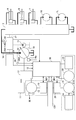
- FIG. 2 is a block diagram showing a configuration example of a drive system of the shovel according to the embodiment of the present invention.
- the mechanical power system is indicated by a double line
- the high-pressure hydraulic line is indicated by a thick solid line
- the pilot line is indicated by a broken line
- the electric drive / control system is indicated by a thin solid line.
- the engine 11 as a mechanical drive unit and the motor generator 12 as an assist drive unit are connected to two input shafts of a transmission 13, respectively.
- a main pump 14 and a pilot pump 15 are connected to the output shaft of the transmission 13 as hydraulic pumps.
- a control valve 17 is connected to the main pump 14 via a high pressure hydraulic line 16. The main pump 14 and each valve in the control valve 17 may be connected in parallel.
- the main pump 14 is a component of a hydraulic drive system in the excavator, and is a swash plate type variable displacement hydraulic pump in this embodiment.
- the regulator 14 a is a device that controls the discharge amount of the main pump 14.
- the regulator 14 a controls the discharge amount of the main pump 14 by adjusting the swash plate tilt angle of the main pump 14 in accordance with a command from the controller 30.
- the control valve 17 is a hydraulic control device that controls a hydraulic system in the excavator.
- the hydraulic actuators such as the right traveling hydraulic motor 1R, the left traveling hydraulic motor 1L, the boom cylinder 7, the arm cylinder 8, and the bucket cylinder 9 are connected to the control valve 17 via a high pressure hydraulic line.
- the hydraulic system includes a right traveling hydraulic motor 1R, a left traveling hydraulic motor 1L, a boom cylinder 7, an arm cylinder 8, a bucket cylinder 9, a main pump 14, and a control valve 17.
- the motor generator 12 is connected to a power storage system 120 including a capacitor as a capacitor via an inverter 18 as a motor generator control unit.
- the power storage system 120 is connected to a turning electric motor 21 as an electric working element via an inverter 20 as a motor generator control unit.
- a resolver 22, a mechanical brake 23, and a turning transmission 24 are connected to the rotating shaft 21 ⁇ / b> A of the turning electric motor 21.
- An operation device 26 is connected to the pilot pump 15 through a pilot line 25.
- the turning electric motor 21, the inverter 20, the resolver 22, the mechanical brake 23, and the turning transmission 24 constitute an electric turning system as a load drive system.
- the turning electric motor 21 has a turning drive function and rotates the upper turning body 3.
- a configuration including a hydraulic drive / brake system as a turning system may be used.
- This embodiment exhibits a remarkable effect particularly in a configuration in which no hydraulic pressure is used for turning driving.
- a configuration in which hydraulic pressure is not used for turning driving will be described.
- the operation device 26 generates information related to the operation amount.
- the information can be supplied directly or converted to the drive device or other device directly or indirectly through the controller 30 or the like.
- the operating device 26 includes a lever 26A, a lever 26B, and a pedal 26C.
- the lever 26A, the lever 26B, and the pedal 26C are connected to the control valve 17 and the pressure sensor 29 via hydraulic lines 27 and 28, respectively.
- the pressure sensor 29 is a sensor that detects the operation content of the operation device 26 in the form of pressure, and outputs a detection value to the controller 30.
- the discharge pressure sensor 29 ⁇ / b> A is a sensor that detects the discharge pressure of the main pump 14, and outputs a detection value to the controller 30.
- Temperature sensors M2 and M3 are sensors that detect the temperature of the power storage system 120, and output detected values to the controller 30.
- the temperature sensors M ⁇ b> 2 and M ⁇ b> 3 are composed of thermistors and output detection values to the controller 30.
- the controller 30 is a control device as a main control unit that performs drive control of the excavator.
- the controller 30 is configured by an arithmetic processing unit including a CPU and an internal memory, and realizes various functions by causing the CPU to execute a drive control program stored in the internal memory.
- the controller 30 receives various detection values from the pressure sensor 29, the discharge pressure sensor 29A, the temperature sensor M2, and the temperature sensor M3, for example, and executes various calculations to apply various calculations to the engine 11, the regulator 14a, the power storage system 120, and the like. Output a command. For example, when controller 30 determines that the temperature of power storage system 120 is lower than a predetermined temperature based on the detected value of temperature sensor M2, warm-up of power storage system 120 is started. Further, the controller 30 continues warming up of the power storage system 120 even when it is determined that warming up of the hydraulic drive system has started based on the detection values of the pressure sensor 29 and the discharge pressure sensor 29A. A detailed description of the warm-up of the hydraulic drive system and the warm-up of the power storage system 120 will be described later.
- FIG. 3 is a block diagram showing the configuration of the power storage system 120.
- the power storage system 120 includes a capacitor 19 as a first battery, a buck-boost converter 100, and a DC bus 110 as a bus line.
- the first battery is a device that can charge and discharge electric power, such as a lithium ion capacitor, an electric double layer capacitor, and a lithium ion battery.
- the capacitor 19 is a lithium ion capacitor.
- the power storage system 120 is provided with a capacitor voltage detector 112 for detecting the capacitor voltage value and a capacitor current detector 113 for detecting the capacitor current value.
- the capacitor voltage value and the capacitor current value are supplied to the controller 30.
- the capacitor voltage value corresponds to the terminal voltage of the capacitor 19.
- the open-circuit voltage of the capacitor 19 is Vc [V]
- the internal resistance of the capacitor 19 is R [ ⁇ ]
- the magnitude of the discharge current flowing from the capacitor 19 to the buck-boost converter 100 is Id [A]
- the discharge power W1 of the capacitor 19 V1 ⁇ Id.
- the charging current flowing from the buck-boost converter 100 to the capacitor 19 is Ic
- the calorific value Q1 during discharging of the capacitor 19 is represented by Id 2 ⁇ R
- the calorific value Q2 during charging is represented by Ic 2 ⁇ R.
- the charging rate (SOC) of the capacitor 19 is expressed by the following equation, where the minimum voltage of the capacitor 19 is Vmin and the maximum voltage is Vmax.
- the high SOC of the capacitor 19 means that the open circuit voltage Vc is high, the discharge current Id when realizing the predetermined discharge power W1 can be small, and the heat generation amount Q1 during discharge is also small. Therefore, the discharge efficiency is high.
- the charging current Ic for realizing the predetermined charging power W2 is small, and the heat generation amount Q2 at the time of charging is also small, so that the charging efficiency is high.
- the temperature sensor M2 provided in the power storage system 120 detects the temperature of the capacitor 19 (capacitor temperature).
- the temperature sensor M3 detects the temperature of the buck-boost converter 100.
- the capacitor temperature may be detected in such a manner that the relative value of the temperature of the capacitor 19 with respect to an appropriate reference is known, and is usually measured directly. Information related to the capacitor temperature may be used. For example, it may be detected indirectly by detecting the temperature of the cooling water used for cooling the capacitor 19. Alternatively, it may be detected indirectly by detecting the temperature of a heat medium other than the cooling water that affects the temperature of the capacitor 19. It may be an environmental temperature such as temperature.
- the temperature sensor M2 includes a thermistor attached to the electrode of the capacitor cell, detects the capacitor temperature, and outputs the detected value to the controller 30.
- the step-up / step-down converter 100 performs control to switch between the step-up operation and the step-down operation so that the DC bus voltage value falls within a certain range according to the operating state of the motor generator 12 and the turning electric motor 21.
- the voltage of the DC bus 110 is detected by the DC bus voltage detection unit 111.
- the DC bus 110 is disposed between each of the inverters 18 and 20 and the step-up / down converter 100, and transfers power between the capacitor 19, the motor generator 12, and the turning electric motor 21.
- the controller 30 converts the signal supplied from the pressure sensor 29 into a speed command, and performs drive control of the turning electric motor 21.
- the signal supplied from the pressure sensor 29 corresponds to a signal representing an operation amount when the operation device 26 is operated to turn the turning mechanism 2.
- the controller 30 performs operation control of the motor generator 12 (switching between electric (assist) operation or power generation operation) and also performs charge / discharge control of the capacitor 19 by drivingly controlling the step-up / down converter 100.
- the controller 30 corresponds to the charging state of the capacitor 19, the operation state of the motor generator 12 (assist operation or power generation operation), and the operation state of the turning motor 21 (power running operation or regenerative operation). 19 charge / discharge control is performed.
- a DC bus voltage value, a capacitor voltage value, and a capacitor current value are considered.
- the electric power generated by the motor generator 12 which is an assist motor is supplied to the DC bus 110 via the inverter 18 and then supplied to the capacitor 19 via the buck-boost converter 100, or It can be supplied to the turning electric motor 21 via the inverter 20.
- the regenerative power generated by the regenerative operation of the turning electric motor 21 is supplied to the DC bus 110 via the inverter 20 and then supplied to the capacitor 19 via the step-up / down converter 100 or via the inverter 18.
- the electric power stored in the capacitor 19 can be supplied to at least one of the motor generator 12 and the turning electric motor 21 via the step-up / down converter 100 and the DC bus 110.
- the controller 30 charges and discharges the capacitor 19 so that the capacitor 19 can maintain or be easily maintained at a predetermined charging rate (SOC). If the predetermined SOC is changed to an appropriate range according to the environment surrounding the capacitor 19, there is a merit described later. At least, even if the capacitor 19 exchanges power with various electric loads and accepts it, the capacitor 19 is maintained in a range that does not cause overcharge or overdischarge.
- the SOC of the capacitor 19 may be maintained at a predetermined SOC level (for example, 70%) as the SOC operation. The higher this level, the higher the energy that can be retained. However, as described later, when the environmental temperature is low and the temperature of the capacitor 19 is low, a relatively low level may be preferable.
- the “object other than charging the capacitor 19” includes intentionally applying a load to the engine 11.
- the controller 30 can increase the output of the engine 11 at an arbitrary timing by intentionally applying a load to the engine 11 by causing the motor generator 12 to function as a generator at an arbitrary timing. This is because the engine 11 increases the output in an attempt to maintain a predetermined rotational speed when the load increases. Therefore, the controller 30 instantaneously increases the output of the engine 11 before the hydraulic load is applied to the engine 11, so that when the hydraulic load is actually applied, the rotational speed of the engine 11 is reduced due to insufficient output. Can be prevented.
- the SOC of the capacitor 19 is calculated based on the capacitor voltage value. It may be derived by measuring the internal resistance of the capacitor 19 or may be derived using any other known method.
- the controller 30 determines a charge request value and a discharge request value based on the current SOC value of the capacitor 19 and controls charging and discharging of the capacitor 19.
- the controller 30 causes the motor generator 12 to generate power with the power corresponding to the charge request value (the power generation itself may generate more power), and charges the capacitor 19 with the power corresponding to the charge request value.
- the charge request value may be changed depending on the current SOC, electric motor, and generator state. When the charge request value is zero, the capacitor 19 is not charged. However, it does not prohibit the motor generator 12 from functioning as a generator for other purposes.
- the controller 30 discharges the power of the capacitor 19 based on the required discharge value (if the power required for turning and assist is low, the electric power is equal to or lower than the required discharge value). May be discharged.)
- the required discharge value may be changed depending on the current SOC, electric motor, and generator state. If the output [kW] required for driving the turning electric motor 21 is larger than the electric power corresponding to the required discharge value, the motor generator 12 is caused to function as a generator. This is because the turning electric motor 21 is driven by the electric power generated by the motor generator 12 and the electric power discharged by the capacitor 19. Further, the controller 30 does not discharge the capacitor 19 when the required discharge value is zero.
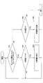
- FIG. 4 is a flowchart showing the flow of the required value derivation process, and the controller 30 repeatedly executes the required value derivation process at a predetermined control cycle.
- the controller 30 acquires the SOC of the capacitor 19 (step S1).
- the controller 30 detects the state of the turning electric motor 21 (step S2). From the turning speed calculated based on the output of the resolver 22, the operating state and the stopped state of the turning electric motor 21 are determined. The power running operation state and the regenerative operation state of the turning electric motor 21 are discriminated from the turning torque and the turning speed calculated based on the current flowing through the inverter 20.
- Step S1 and Step S2 are in no particular order, and the controller 30 may acquire the SOC of the capacitor 19 after detecting the state of the turning electric motor 21 or may execute two processes simultaneously.
- the controller 30 derives a charge request value based on the SOC of the capacitor 19 and the state of the turning electric motor 21 (step S3).
- the SOC / request value correspondence table stored in the internal memory may be referred to.
- a required discharge value is derived based on the SOC of the capacitor 19 and the state of the turning electric motor 21 (step S4).
- the controller 30 may refer to the SOC / requested value correspondence table used when deriving the charge request value.
- FIG. 5 is a diagram for explaining an example of the SOC / required value correspondence table.
- FIG. 5 is a graph showing the relationship between the SOC of the capacitor 19, the required discharge value, and the required charge value.
- the horizontal axis corresponds to SOC [%], and the vertical axis corresponds to the required value.
- the required discharge value is a positive value and the required charge value is a negative value.
- the charge request value in FIG. 5 is for causing the motor generator 12 to function as a generator for charging the capacitor 19.
- the regenerative electric power of the turning electric motor 21 is charged in the capacitor 19 separately from the charging by the electric power generated by the motor generator 12 according to the charging request value.
- the charge request line CL1 indicated by a broken line in FIG. 5 represents a transition of the charge request value employed when the turning electric motor 21 is in the power running operation state. Further, when the SOC is 40 [%] or less, the charge request value becomes the value C1, and even when the SOC further decreases, the value C1 is constant. The value gradually approaches zero until the SOC exceeds 40 [%] and reaches 45 [%]. When the SOC is 45 [%] or more, the value becomes zero (including the vicinity of zero; the same applies hereinafter). . When the charge request line CL1 is employed, the SOC is more likely to be increased when it is 40 [%] or less than when it exceeds 40 [%].
- the charging rate increases from when the SOC is relatively low, and is easily maintained between 40% and 45%. Further, even if the SOC further decreases, the value C1 is set relatively low, so that the amount of power generation is kept low and the engine output is easily directed to the hydraulic load and the turning load.
- a charging request line CL2 indicated by a one-dot chain line in FIG. 5 represents a transition of a charging request value adopted when the turning electric motor 21 is in a regenerative operation state.
- the charge request value becomes the value C2, and even if the SOC further decreases, the value C2 is constant. It represents that the value gradually approaches zero until the SOC exceeds 40 [%] and reaches 60 [%], and the value becomes zero when the SOC is 60 [%] or more.
- the charge request line CL2 is employed, the SOC is more likely to be increased when it is 40 [%] or less than when it exceeds 40 [%]. Also, the SOC is easily maintained in the vicinity of 45 to 60 [%].
- the value C2 is set to be relatively low, so that the amount of power generation is kept low and the engine output is easily directed to the hydraulic load and the turning load.
- the value C2 is more easily charged than the value C1, because the power generation amount to the turning load does not need to be considered much because the turning is being regenerated.
- a charging request line CL3 indicated by a two-dot chain line in FIG. 5 represents a transition of a charging request value adopted when the turning electric motor 21 is stopped. Further, when the SOC is 40 [%] or less, the charge request value becomes the value C3, gradually approaches the value zero until the SOC exceeds 40 [%] and reaches 60 [%], and the SOC is 60 [%] or more. Indicates that the value is zero. When the charge request line CL3 is employed, the SOC is more likely to be increased when it is 40 [%] or less than when it exceeds 40 [%]. Therefore, it is easily maintained between 45 and 60 [%].
- the value C3 is set relatively low, so that the amount of power generation is kept low, and the engine output is easily directed to the hydraulic load and the turning load.
- the level of the value C3 is lower than the value C2 and higher than the value C1. This is because the turning is stopped.
- a discharge request line DL1 indicated by a broken line in FIG. 5 represents a transition of a discharge request value adopted when the turning electric motor 21 is in a power running operation state.
- the SOC when the SOC is 60 [%] or less, the required discharge value becomes zero, the SOC increases at a constant rate from 60 [%] to 100 [%], and the SOC reaches 100 [%]. When it reaches, it represents that the value becomes D1.
- the discharge request line DL1 is employed, the SOC can be discharged as the level becomes higher, and the driving force of the electric motor (for example, turning) can be increased. Accordingly, the SOC is easily reduced and is easily maintained in the vicinity of 60 [%].
- the discharge request line DL2 indicated by a one-dot chain line in FIG. 5 represents a transition of the discharge request value employed when the turning electric motor 21 is in the regenerative operation state. Further, when the SOC is 70 [%] or less, the required discharge value becomes zero, the SOC increases at a constant rate from 70 [%] to 80 [%], and the SOC is 80 [%] or more. In this case, the value D2 is represented.
- the discharge request line DL2 is adopted, the SOC can be discharged more when it is 80 [%] or more than when it is less than 80 [%], and the driving force of the electric motor (for example, assist) can be increased. Accordingly, the SOC is easily reduced, and is easily maintained between 70 and 80 [%], particularly in the vicinity of 70 [%].
- a discharge request line DL3 indicated by a two-dot chain line in FIG. 5 represents a transition of the discharge request value that is adopted when the turning electric motor 21 is in a stopped state. Further, when the SOC is 70 [%] or less, the required discharge value becomes zero, the SOC increases at a constant rate from 70 [%] to 85 [%], and the SOC is 85 [%] or more. In this case, the value D3 is represented.
- the discharge request line DL3 is employed, the SOC can be increased when the SOC is 85 [%] or more compared to when the SOC is less than 85 [%], but the SOC is easily reduced accordingly. Therefore, it is easily maintained between 70 and 85 [%], particularly in the vicinity of 70 [%].
- the graph of FIG. 5 shows that when the current SOC of the capacitor 19 is 70 [%] and the current state of the turning electric motor 21 is a power running state, the charge request value is zero and the discharge request value is D4. Represents that. If the current SOC of the capacitor 19 is 30 [%] and the current state of the turning electric motor 21 is in the regenerative operation state, this indicates that the charge request value is C2 and the discharge request value is zero.
- the charging of the capacitor 19 by the power generation and turning regeneration of the motor generator 12 and the discharging of the capacitor 19 for assisting and turning the motor generator 12 are based on a specific discharge request line and a charge request line. Therefore, it is executed accordingly.
- the power storage system 120 can easily generate a driving force by discharging, suppresses an increase in the load of the engine 11 by power generation, and has a high workability.
- the controller 30 controls charging / discharging of the capacitor 19 using the charge request value and the discharge request value (hereinafter referred to as “turning power running”). "Time processing”) will be described.
- the controller 30 determines whether or not an output (hereinafter referred to as “required output”) required for the turning drive of the turning electric motor 21 is equal to or less than a discharge request value (step S11). This is for determining whether or not the turning electric motor 21 can be driven only by the discharge power.
- the controller 30 derives a required output from the product of the turning speed calculated based on the output of the resolver 22 and the turning torque calculated based on the current flowing through the inverter 20. Then, the controller 30 compares the required output with the required discharge value derived by the required value derivation process of FIG.
- the controller 30 drives the turning electric motor 21 only with the electric power (discharge power) discharged from the capacitor 19 (step S12).
- step S13 the controller 30 determines whether the required charge value is zero (step S13).
- a charge request value of zero may be adopted to control so that no further charging is performed when the SOC is greater than or equal to a predetermined value based on the charge request line used. In this case, charging of the capacitor 19 is stopped. When the charge request value is not zero, a part of the generated power is used for charging.
- the controller 30 determines whether the required output is equal to or less than the sum of the discharge request value and the power generation limit value (step S14). This is to determine whether or not the turning electric motor 21 can be driven only by the discharged power and the generated power.
- the power generation limit value means the maximum value of electric power that can be generated by the motor generator 12.
- the controller 30 determines whether the required discharge value is zero (step S15).
- a discharge request value of zero may be adopted to control so that no further discharge occurs when the SOC is below a predetermined value based on the used discharge request line.
- the controller 30 drives the turning electric motor 21 only with electric power (generated electric power) generated by the motor generator 12 (step S16).
- the controller 30 drives the turning electric motor 21 with the discharge electric power discharged from the capacitor 19 and the electric power generated by the motor generator 12 ( Step S17).
- step S14 If it is determined that the required output is greater than the sum of the required discharge value and the power generation limit value (NO in step S14), the controller 30 is operated with a discharge power greater than the discharge power corresponding to the required discharge value discharged by the capacitor 19, and The turning electric motor 21 is driven with the generated electric power corresponding to the electric power generation limit value generated by the electric generator 12 (step S19). This is because the required output required by the turning electric motor 21 cannot be supplied with the generated power corresponding to the power generation limit value and the discharge power corresponding to the required discharge value. However, you may control so that turning output may be suppressed. The discharge from the capacitor 19 can be suppressed to a value equivalent to the required discharge value.
- step S13 the controller 30 determines whether the required output is equal to or greater than the value obtained by subtracting the charge request value from the power generation limit value (step S18). This is for determining whether the required output required by the turning electric motor 21 cannot be supplied by the motor generator 12 alone.
- the controller 30 When it is determined that the required output is equal to or greater than the value obtained by subtracting the charge request value from the power generation limit value (YES in step S18), the controller 30 has a discharge power greater than the discharge power corresponding to the discharge request value discharged by the capacitor 19, The turning electric motor 21 is driven with the generated electric power corresponding to the electric power generation limit value generated by the motor generator 12 (step S19).
- the capacitor 19 When the capacitor 19 is charged with the generated power corresponding to the charge request value generated by the motor generator 12, the capacitor 19 cannot be discharged, and the motor generator 12 alone cannot supply the required output required for the turning motor 21. It is. However, you may control so that turning output may be suppressed.
- the discharge from the capacitor 19 can be suppressed to a value equivalent to the required discharge value.
- the controller 30 uses the generated power generated by the motor generator 12 only to turn the turning motor 21.
- the capacitor 19 is charged with the generated power corresponding to the charge request value generated by the motor generator 12 (step S20). That is, the motor generator 12 generates power corresponding to the required output and generates power corresponding to the charge request value.
- the controller 30 uses the charge request value and the discharge request value to control charging / discharging of the capacitor 19 (hereinafter referred to as “turning regeneration”). "Time processing”) will be described.
- the controller 30 determines whether or not the discharge request value is zero (step S21).
- Step S21 When it is determined that the required discharge value is zero (YES in step S21), that is, when the discharge of the capacitor 19 is stopped, the controller 30 determines whether or not the required charge value is not zero ( Step S22). This is to determine whether charging of the capacitor 19 is stopped.
- step S22 If it is determined that the charge request value is not zero (YES in step S22), the controller 30 charges the capacitor 19 with all the regenerative power regenerated by the turning motor 21 and the generated power corresponding to the charge request value (step S22). S23).
- step S22 When it is determined that the charge request value is zero (NO in step S22), there is no generated power, and the controller 30 charges the capacitor 19 with all the regenerative power regenerated by the turning motor 21 (step S24). ).
- step S21 the controller 30 determines whether or not the regenerative power is greater than the required discharge value (step S25). This is to determine whether to charge the capacitor 19.
- the regenerative power is represented by a negative value, and the required discharge value is represented by a positive value. Therefore, strictly speaking, the controller 30 determines whether or not the absolute value of the regenerative power is larger than the required discharge value.
- the controller 30 charges the capacitor 19 by the difference between the regenerative power and the required power value (step S26).
- the controller 30 supplies a part of the regenerative power corresponding to the required discharge value from the turning motor 21 to the motor generator 12 to cause the motor generator 12 to function as the motor, and the remaining part of the regenerative power. Is charged in the capacitor 19.
- the controller 30 directs the sum of the regenerative power and the power corresponding to the required discharge value to the motor generator 12 (step S27). ).
- the controller 30 supplies all of the regenerative power from the turning motor 21 to the motor generator 12, and supplies power corresponding to the discharge required value from the capacitor 19 to the motor generator 12.
- the machine 12 is caused to function as an electric motor.
- the electric power that can be accepted by the motor generator 12 that functions as an electric motor is limited by a predetermined assist limit value.
- the assist limit value means the maximum value of electric power that can be accepted by the motor generator 12 functioning as an electric motor. This is to prevent the assist output from becoming too large and the engine 11 from blowing up. Therefore, when the sum of the regenerative power and the power corresponding to the discharge request value exceeds the power corresponding to the assist limit value, the controller 30 is discharged from the capacitor 19 by reducing the power corresponding to the discharge request value. The electric power supplied to the motor generator 12 is made equal to the electric power corresponding to the assist limit value.
- the controller 30 By repeatedly executing the above-described turning regeneration processing, the controller 30 causes the capacitor 19 to indicate the SOC (for example, 30%) corresponding to the discharge request value of zero as indicated by the charge request line CL2 of FIG. Then, all of the regenerative power is supplied to the capacitor 19 to charge the capacitor 19, and the electric power corresponding to the charge request value is generated by the motor generator 12, and the capacitor 19 is charged with the generated power. In this way, when the SOC of the capacitor 19 is in a low state, the controller 30 causes the motor generator 12 to generate power and charge the capacitor 19 even during turning regeneration, thereby increasing the SOC. return.
- the SOC for example, 30%
- the controller 30 prevents the capacitor 19 from being overcharged as indicated by a discharge request line DL2 in FIG. For example, when the capacitor 19 indicates an SOC (for example, a value greater than 70%) corresponding to a discharge request value that is not zero, if the regenerative power is greater than the discharge request value, the capacitor 19 is charged with the differential power. Let Then, electric power corresponding to the required discharge value is supplied from the turning electric motor 21 to the motor generator 12 to cause the motor generator 12 to function as an electric motor. In this way, the controller 30 prevents overcharging of the capacitor 19 by consuming a part of the regenerative power by the motor generator 12 even when large regenerative power is generated by turning 180 degrees or the like. To do.
- SOC for example, a value greater than 70%
- the controller 30 12 when the capacitor 19 indicates an SOC (for example, a value greater than 70%) corresponding to a discharge request value that is not zero, if the regenerative power is equal to or smaller than the discharge request value, the controller 30 12 is made to function as an electric motor. For example, the sum of the regenerative power and the power corresponding to the required discharge value is directed to the motor generator 12 until the SOC (for example, 70%) corresponding to the discharge required value of zero is reached, and the motor generator 12 is moved to the motor. To function as. In this way, the controller 30 prevents the capacitor 19 from being overcharged.
- SOC for example, a value greater than 70%
- FIG. 8 is a flowchart showing the flow of the turning stop process, and the controller 30 repeatedly executes the turning stop process at a predetermined control cycle when the turning electric motor 21 is stopped.
- the controller 30 determines whether or not the discharge request value is zero (step S31). This is to determine whether or not the discharge of the capacitor 19 is stopped.
- Step S31 When it is determined that the required discharge value is zero (YES in step S31), that is, when discharging of the capacitor 19 is stopped, the controller 30 determines whether or not the required charge value is not zero ( Step S32). This is to determine whether charging of the capacitor 19 is stopped.
- step S32 When it is determined that the charge request value is not zero (YES in step S32), that is, when charging of the capacitor 19 is not stopped, the controller 30 causes the motor generator 12 to function as a generator, and the motor generator 12 The capacitor 19 is charged with the generated electric power generated by (step S33).
- step S32 If it is determined that the charge request value is zero (NO in step S32), that is, if charging of the capacitor 19 is stopped, the controller 30 does not charge the capacitor 19. Therefore, the motor generator 12 is not allowed to function as a generator only for charging the capacitor 19. However, it does not prohibit the motor generator 12 from functioning as a generator for other purposes.
- step S31 when it is determined that the required discharge value is not zero (NO in step S31), that is, when the discharge of the capacitor 19 is not stopped, the controller 30 drives the motor generator 12 with the electric power discharged from the capacitor 19. (Step S34).
- the controller 30 prevents the capacitor 19 from being overdischarged, as indicated by the charge request line CL3 in FIG.
- the capacitor 19 indicating the SOC (for example, 30%) corresponding to the charge request value that is not zero is charged to the SOC (for example, 60%) corresponding to the zero charge request value.
- the predetermined case includes, for example, a case where the discharge of the capacitor 19 for causing the motor generator 12 to function as an electric motor to increase the load of the engine 11 increases and the SOC of the capacitor 19 is low.
- the controller 30 replaces the capacitor 19 indicating the SOC (for example, 90%) corresponding to the discharge request value that is not zero with the SOC ( For example, 70%). In this way, the controller 30 can prevent the SOC of the capacitor 19 from becoming excessively high even when the capacitor 19 is frequently charged.
- the capacitor 19 is, for example, an opportunity for the motor generator 12 to function as a generator to intentionally apply a load to the engine 11, or an opportunity for the motor generator 12 to function as an electric motor in order to keep the load on the engine 11 constant. The battery is charged more frequently as the number increases.
- controller 30 prevents the capacitor 19 from being charged / discharged when the capacitor 19 indicates an SOC (for example, 60% or more and 70% or less) in which both the charge request value and the discharge request value are zero.
- SOC for example, 60% or more and 70% or less
- the controller 30 controls charging / discharging of the capacitor 19 based on the charge request value and the discharge request value corresponding to the current SOC of the capacitor 19. Therefore, charging / discharging of the capacitor 19 can be controlled more appropriately.
- controller 30 changes the charge request value and the discharge request value according to the state of the turning electric motor 21. Therefore, charging / discharging of the capacitor 19 can be controlled more appropriately.
- FIG. 9 is a conceptual diagram illustrating the pump maximum output increase / decrease process.
- the output (absorption horsepower) of the main pump 14 is calculated as the product of the discharge amount and the discharge pressure of the main pump 14.
- the controller 30 derives the engine output EP.
- the controller 30 receives a detection value of an engine speed sensor (not shown), and derives an engine output EP with reference to an engine speed / engine output correspondence map stored in advance in an internal memory.
- the controller 30 derives an assist output AP.
- the controller 30 derives the power exchanged between the motor generator 12 and the capacitor 19 as the assist output AP based on the detection values of the capacitor voltage detection unit 112 and the capacitor current detection unit 113.
- the assist output AP has a positive value when the motor generator 12 functions as a motor (when the capacitor 19 discharges), and when the motor generator 12 functions as a generator (the capacitor 19). Becomes negative when charging).
- the controller 30 adds the engine output EP and the assist output AP to derive the total output TP.
- the motor generator 12 functions as a motor (when the capacitor 19 discharges)
- the total output TP becomes a value larger than the engine output EP by the assist output AP
- the motor generator 12 functions as a generator.
- the capacitor 19 is charged, the value is smaller than the engine output EP by the assist output AP.
- the controller 30 derives the pump current PC.
- the controller 30 receives the detection value of the engine speed sensor and derives the pump current PC by referring to the total output / pump current correspondence map corresponding to the engine speed stored in advance in the internal memory.
- the controller 30 outputs a pump current PC to a regulator (not shown) of the main pump 14.
- the regulator is a device that controls the discharge amount of the main pump 14 by adjusting the tilt angle of the swash plate of the main pump 14 in accordance with a command from the controller 30.
- the regulator reduces the discharge amount of the main pump 14 as the pump current PC is smaller.
- the controller 30 increases the pump current PC and increases the pump maximum output of the main pump 14 as the assist output AP increases. That is, if the engine speed is constant, the pump current PC can be increased and the pump maximum output of the main pump 14 can be increased as the power consumption of the motor generator 12 (discharge amount of the capacitor 19) is increased. .
- the total output TP also increases and a margin is generated in the total output TP, so that the main pump 14 can efficiently use the margin.
- the output (absorption horsepower) of the main pump 14 is controlled within the range of the increased pump maximum output.
- the assist force may be increased without adjusting the regulator to absorb the load of the main pump 14.
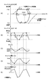
- FIG. 10 is a diagram showing another example of the SOC / required value correspondence table, which corresponds to FIG. Specifically, FIG. 10 is a graph showing a relationship between the SOC of the capacitor 19 and the required discharge value and the required charge value when the turning electric motor 21 is in a powering operation state, and the horizontal axis indicates the SOC [%. ], And the vertical axis corresponds to the output [kW].
- the discharge request line DL (20 ° C.) indicated by the broken line in FIG. 10 represents the transition of the discharge request value adopted when the turning electric motor 21 is in the power running state and the capacitor temperature is 20 ° C. This corresponds to the discharge request line DL1.
- a discharge request line DL (0 ° C.) indicated by a broken line represents a transition of the discharge request value adopted when the capacitor temperature is 0 ° C.
- a required discharge line DL ( ⁇ 10 ° C.) indicated by a broken line represents a change in required discharge value adopted when the capacitor temperature is ⁇ 10 ° C.
- a required discharge line DL ( ⁇ 20 ° C.) indicated by a broken line is It represents the transition of the required discharge value adopted when the capacitor temperature is ⁇ 20 ° C.
- the charging request line CL (20 ° C.) indicated by the dotted line in FIG. 10 represents the transition of the charging request value adopted when the turning electric motor 21 is in the powering operation state and the capacitor temperature is 20 ° C. This corresponds to the charge request line CL1.
- a charging request line CL (0 ° C.) indicated by a dotted line represents a transition of a charging request value adopted when the capacitor temperature is 0 ° C.
- a charge request line CL ( ⁇ 10 ° C.) indicated by a dotted line represents a transition of a charge request value adopted when the capacitor temperature is ⁇ 10 ° C.
- a charge request line CL ( ⁇ 20 ° C.) indicated by a dotted line is It represents the transition of the required charging value adopted when the capacitor temperature is ⁇ 20 ° C.
- the discharge limit line UL (20 ° C.) indicated by the solid line in FIG. 10 represents the transition of the discharge limit value when the capacitor temperature is 20 ° C.
- the discharge limit value means the maximum value of power that can be discharged by the capacitor 19 and is used to prevent the capacitor 19 from being overdischarged. Specifically, it is used when limiting the discharge power of the capacitor 19 so that the terminal voltage of the capacitor 19 does not fall below a predetermined lower limit voltage. In FIG. 10, when SOC is 30 [%], the discharge power of the capacitor 19 is limited by the value D10. If the discharge power of the capacitor 19 exceeds the value D10, the terminal voltage may fall below the lower limit voltage.
- a discharge limit line UL (0 ° C.) indicated by a solid line represents a transition of the discharge limit value when the capacitor temperature is 0 ° C.
- the discharge limit line UL ( ⁇ 10 ° C.) indicated by the solid line represents the transition of the discharge limit value when the capacitor temperature is ⁇ 10 ° C.
- the discharge limit line UL ( ⁇ 20 ° C.) indicated by the solid line is the capacitor temperature. Represents the transition of the discharge limit value when -20 ° C.
- a charging limit line BL (20 ° C.) indicated by a solid line in FIG. 10 represents a transition of the charging limit value when the capacitor temperature is 20 ° C.
- the charge limit value means a maximum value of power that can be charged by the capacitor 19 and is used to prevent the capacitor 19 from being overcharged. Specifically, it is used to limit the charging power of the capacitor 19 so that the terminal voltage of the capacitor 19 does not exceed a predetermined upper limit voltage. In FIG. 10, when the SOC is 55 [%], the charging power of the capacitor 19 is limited by the value C10. If the charging power of the capacitor 19 exceeds the value C10, the terminal voltage may exceed the upper limit voltage.
- a charging limit line BL (0 ° C.) indicated by a solid line represents a transition of the charging limit value when the capacitor temperature is 0 ° C.
- the charging limit line BL ( ⁇ 10 ° C.) indicated by a solid line represents the transition of the charging limit value when the capacitor temperature is ⁇ 10 ° C.
- the charging limit line BL ( ⁇ 20 ° C.) indicated by the solid line is the capacitor temperature. Represents the transition of the charging limit value when -20 ° C.
- the charge limit value and the discharge limit value may be collectively referred to as a charge / discharge limit value.
- the discharge request line DL (20 ° C.) has a value of zero when the SOC is 60% or less, and has a change rate ⁇ until the SOC exceeds 60% and reaches 100%.
- the discharge request line DL (0 ° C.) has a value of zero when the SOC is equal to or less than 48 [%], and increases at a change rate ⁇ until the SOC exceeds 48 [%] and reaches 100 [%].
- the discharge request line DL ( ⁇ 10 ° C.) becomes zero when the SOC is 40% or less, and increases at a change rate ⁇ until the SOC exceeds 40% and reaches the discharge limit line.
- the discharge request line DL ( ⁇ 20 ° C.) is zero when the SOC is 25% or less, and the discharge limit line UL ( ⁇ 20 until the SOC exceeds 25% and reaches 100%. C). Note that the rate of change ⁇ with respect to the SOC of the discharge request line DL (20 ° C.), the discharge request line DL (0 ° C.), and the discharge request line DL ( ⁇ 10 ° C.) is equal in the region below the corresponding discharge limit line.
- the controller 30 reduces the SOC (discharge start charging rate: discharge start SOC) when the required discharge value becomes greater than the value zero as the capacitor temperature decreases, so that the controller 30 performs the power running operation of the turning electric motor 21. And SOC at the time of regenerative operation can be reduced.
- the SOC of the capacitor 19 is 60% to 80% when the power running operation and the regenerative operation are performed by adopting the discharge request line DL (20 ° C.).
- the range of [%] changes.
- the controller 30 can suppress the charging power, which is the regenerative power generated by the turning electric motor 21 during turning regeneration, from exceeding the charge limit line.
- the SOC when the regenerative operation is performed is 55 [%]
- the capacitor temperature is 20 ° C.
- the capacitor 19 causes the terminal voltage to exceed the upper limit voltage.
- the charging power of value C10 can be accepted while preventing.
- the capacitor 19 cannot accept the charging power larger than the value C11 in order to prevent the terminal voltage from exceeding the upper limit voltage. Furthermore, if the capacitor temperature is ⁇ 10 ° C., charging power greater than the value C12 cannot be accepted, and if the capacitor temperature is ⁇ 20 ° C., charging power greater than the value C13 cannot be accepted. Thus, the charging power that can be received by the capacitor 19 (acceptable charging power) decreases as the capacitor temperature decreases. On the other hand, the acceptable charging power increases as the SOC decreases. From this relationship, the controller 30 reduces the SOC at the time of the power running operation and the regenerative operation of the turning electric motor 21 by lowering the discharge start SOC as the capacitor temperature is lower. (Charging power) can be prevented from exceeding the charge limit line.
- the internal resistance R of the capacitor 19 increases as the capacitor temperature decreases. Furthermore, the controller 30 lowers the discharge start SOC as the capacitor temperature is lower, and therefore lowers the terminal voltage of the capacitor 19 during charging and discharging. Therefore, the discharge current that flows to obtain the same discharge power becomes large, and the charge current that flows to obtain the same charge power becomes large. Therefore, the calorific value of the capacitor 19 increases as the capacitor temperature decreases due to an increase in the internal resistance R and an increase in charge / discharge current. As a result, the warm-up of the capacitor 19 can be promoted.
- the warm-up of the capacitor 19 is a process for forcibly increasing the capacitor temperature by charging and discharging the capacitor 19 when the capacitor temperature is equal to or lower than a predetermined temperature. In the present embodiment, if the excavator is in the non-operating state, it is realized by charging and discharging the capacitor 19 using the motor generator 12 or the like even when the engine 11 is idling.
- the internal resistance R of the capacitor 19 is smaller as the capacitor temperature is higher. Furthermore, the controller 30 increases the terminal voltage of the capacitor 19 during charging / discharging in order to increase the discharge start SOC as the capacitor temperature increases. Therefore, the discharge current that flows to obtain the same discharge power is reduced, and the charge current that flows to obtain the same charge power is reduced. Therefore, the heat generation amount of the capacitor 19 becomes smaller as the capacitor temperature is higher in accordance with the decrease in the internal resistance R and the decrease in the charge / discharge current. As a result, heat loss is reduced and the capacitor 19 can be used with high efficiency.
- the controller 30 has a rate of change ⁇ with respect to each SOC of the discharge request line DL (20 ° C.), the discharge request line DL (0 ° C.), and the discharge request line DL ( ⁇ 10 ° C.) in the region below the discharge limit line.
- ⁇ the rate of change ⁇
- the rate of change ⁇ the more easily the required output of the turning electric motor 21 during turning power running exceeds the required discharge value, and power generation by the motor generator 12 is started earlier, and the pump of the main pump 14 Maximum output is limited earlier. For example, when boom-up turning is performed, the ascending speed of the boom 4 decreases at an earlier stage during turning power running.
- the rate of change ⁇ may be set to be relatively large regardless of the capacitor temperature, particularly in a region where the SOC is relatively high. This is because the discharge power is increased as much as possible during the turning power running to prevent overcharging during the subsequent turning regeneration.
- the change rate ⁇ is limited by the discharge limit line in order to protect the capacitor 19. For example, if the rate of change is increased in the discharge request line DL ( ⁇ 20 ° C.) when the capacitor temperature is ⁇ 20 ° C., the discharge power exceeds the discharge limit line UL ( ⁇ 20 ° C.) at the discharge start SOC. This is to cause discharge. Therefore, the change rate ⁇ needs to be appropriately set in consideration of the discharge limit line.
- the discharge request line DL is set to draw a straight line, but may be set to draw a curved line or may be set to draw a broken line.
- FIG. 10 shows the discharge request line DL, the discharge limit line UL, and the charge limit line BL when the capacitor temperatures are 20 ° C., 0 ° C., ⁇ 10 ° C., and ⁇ 20 ° C.
- the discharge request line DL, the discharge limit line UL, and the charge limit line BL exist in increments of temperature.
- FIG. 11 is a diagram showing another example of the discharge request line when the capacitor temperature is ⁇ 10 ° C.
- FIG. 11 shows only the discharge limit line UL ( ⁇ 10 ° C.) and the discharge request lines DLa ( ⁇ 10 ° C.) and DLb ( ⁇ 10 ° C.) when the capacitor temperature is ⁇ 10 ° C. for the sake of clarity.
- the discharge limit line, the discharge request line, and the charge request line at other temperatures are omitted.
- a discharge request line DLa ( ⁇ 10 ° C.) indicated by a dotted line is an example of a transition set to draw a broken line, and the SOC increases at a relatively small change rate from 30 [%] to 47 [%]. . Then, the SOC increases at a relatively large change rate until the SOC reaches 55 [%], and thereafter increases at a relatively small change rate until the SOC reaches 100 [%].
- the controller 30 discharges the capacitor 19 with a relatively large discharge power when the SOC is 47 [%] to 55 [%]. Can be prevented from exceeding the upper limit voltage.
- the discharge request line DLb ( ⁇ 10 ° C.) indicated by the alternate long and short dash line is an example of a transition set to draw a straight line without being restricted by the discharge limit line UL ( ⁇ 10 ° C.), and the SOC is 30 [%].
- the rate of change remains unchanged from 100% to 100%.
- the controller 30 does not suddenly change the required discharge value during turning power running as in the case where the transition is set so as to draw a broken line. A sudden change can be prevented.
- FIG. 12 is a diagram illustrating the relationship between the SOC of the capacitor 19 and the turning speed limit value, where the horizontal axis corresponds to the SOC [%] and the vertical axis corresponds to the turning speed limit value [rpm].
- the acceptable charging power of the capacitor 19 is determined according to the SOC of the capacitor 19 and the capacitor temperature at the start of turning. For example, as shown in FIG. 10, if the capacitor temperature is 0 ° C. and the SOC is 55 [%], the acceptable charge power is a value C11 when the charge limit line BL (0 ° C.) is referred to.
- the maximum braking torque that can be realized within the range of the acceptable charging power is determined, and the maximum turning speed (turning speed limit value) when the maximum braking torque is required is determined.
- the turning speed limit value Ncl is a charging limit value Wcl, a maximum braking torque Tmax, and an electric power corresponding to the assist limit value Wa.
- the start of turning means, for example, the time when the operation amount of the turning operation lever exceeds a predetermined value, the time when the turning speed reaches a predetermined speed, or the like. Further, the controller 30 determines a turning speed limit value every time the turning is started.
- FIG. 12 shows the transition of the turning speed limit value determined as described above with respect to the SOC.
- a turning speed limit line TL (20 ° C.) indicated by a dotted line represents a transition of the turning speed limit value when the capacitor temperature is 20 ° C.
- a turning speed limit line TL (0 ° C.) indicated by a dotted line is It represents the transition of the turning speed limit value when the capacitor temperature is 0 ° C.
- a turning speed limit line TL ( ⁇ 10 ° C.) indicated by a dotted line represents a transition of the turning speed limit value when the capacitor temperature is ⁇ 10 ° C.
- a turning speed limit line TL ( ⁇ 20 ° C.) indicated by a dotted line is It represents the transition of the turning speed limit value when the capacitor temperature is ⁇ 20 ° C.
- the turning speed is electrically or mechanically limited by the upper limit Rmax.
- the turning speed limit value when the SOC is 55 [%] is adopted. This is to prevent the actual maximum turning speed from changing due to the change in the turning speed limit value every time the turning operation is performed. Specifically, when the SOC at the start of turning is 55% or less and the capacitor temperature is ⁇ 10 ° C., the turning speed limit value is set to the value Rb. When the SOC at the start of turning is 55% or less and the capacitor temperature is ⁇ 20 ° C., the turning speed limit value is set to the value Ra.
- the SOC / required value correspondence table as shown in FIG. 10 is employed, when the capacitor temperature is 0 ° C. or lower, the turning operation is usually performed in the range of SOC of 55% or lower. Therefore, even if the turning speed limit value is changed along the turning speed limit line in the range where the SOC is larger than 55%, the actual maximum turning speed does not change every time the turning operation is performed. .
- the controller 30 limits the maximum turning speed according to the capacitor temperature. Further, the controller 30 gradually releases the restriction on the maximum turning speed as the capacitor temperature rises.
- FIG. 13A is a diagram showing the relationship between the turning speed limit value and the turning torque limit value.
- the horizontal axis corresponds to the turning speed limit value [rpm], and the vertical axis represents the turning torque limit value [%. ].
- FIG. 13B is a diagram showing the relationship between the swing speed limit value and the pump current limit value, where the horizontal axis corresponds to the swing speed limit value [rpm] and the vertical axis represents the pump current limit value [mA. ].
- the controller 30 limits the turning speed limit value to the value Rb when the SOC at the start of turning is 55 [%] or less and the capacitor temperature is ⁇ 10 ° C.
- the controller 30 refers to the correspondence table as shown in FIG. 13A and derives the value Sb as the turning torque limit value. Further, the controller 30 refers to the correspondence table as shown in FIG. 13B and derives the value Pb as the pump current limit value.
- the controller 30 limits the turning speed limit value to the value Ra ( ⁇ Rb) when the SOC at the start of turning is 55 [%] or less and the capacitor temperature is ⁇ 20 ° C.
- the controller 30 derives the value Sa ( ⁇ Sb) as the turning torque limit value and the value Pa ( ⁇ Pb) as the pump current limit value.
- the controller 30 determines the turning torque limit value and the pump current limit value every time the turn is started, as with the turning speed limit value.
- the controller 30 can provide the operator with the operating speed of the hydraulic actuator that matches the turning speed, and can prevent the feeling of operation from being impaired.
- the controller 30 When the maximum value Rmax is adopted as the turning speed limit value, the controller 30 derives the value Smax as the turning torque limit value and derives the value Pmax as the pump current limit value. That is, the controller 30 does not limit the maximum turning torque and the pump maximum output when the maximum turning speed is not limited.
- the controller 30 reduces the charge limit value and the discharge limit value and changes the required discharge value in accordance with a decrease in the capacitor temperature.
- each change in the charge limit value and the discharge limit value with respect to the change in the SOC is reduced, and the change in the discharge request value with respect to the change in the SOC is reduced.
- the limit values of the discharge limit line UL and the charge limit line BL are reduced according to the decrease in the capacitor temperature.
- the slope of the discharge request line DL during turning power running is reduced according to the decrease in the capacitor temperature. Therefore, the controller 30 can prevent overcharging and overdischarging of the capacitor 19 even when the turning electric motor 21 is driven in a state where the capacitor temperature is low. As a result, the controller 30 can drive the turning electric motor 21 without adversely affecting the capacitor 19 even before the capacitor 19 is completely warmed up.
- the controller 30 reduces the lower limit of the charging rate of the capacitor 19 that makes the required discharge value larger than zero as the capacitor temperature decreases.
- the controller 30 reduces the discharge start SOC in accordance with the decrease in the capacitor temperature. Therefore, the controller 30 can control charging / discharging of the capacitor 19 during turning power running and turning regeneration so that the SOC of the capacitor 19 changes in a lower range as the capacitor temperature is lower.
- the capacitor temperature is lower, the capacitor 19 can be charged / discharged under conditions where heat is more easily generated, and warming up of the capacitor 19 can be promoted.
- the lower the capacitor temperature the lower the SOC at the start of turning regeneration, so that the terminal voltage of the capacitor 19 can be prevented from reaching the upper limit voltage during turning regeneration, and the capacitor 19 can be prevented from being overcharged.
- the controller 30 adjusts the content of the SOC / required value correspondence table according to the capacitor temperature when the turning electric motor 21 is in the power running state.
- the controller 30 does not adjust the contents of the SOC / required value correspondence table only when the turning electric motor 21 is in the power running operation state, but also when the turning electric motor 21 is in the regenerative operation state and the stopped state.
- the contents of the SOC / required value correspondence table may be adjusted according to the temperature.
- FIG. 14 is a diagram showing still another example of the SOC / required value correspondence table, and corresponds to FIG. 5 and FIG. Specifically, FIG. 14 is a graph showing a relationship between the SOC of the capacitor 19 and the required discharge value and the required charge value that are employed when the turning electric motor 21 is in the regenerative operation state.
- the controller 30 has an SOC / required value correspondence table for turning regeneration as well as an SOC / required value correspondence table for turning power running. Then, similarly to the turning power running, the controller 30 controls charging / discharging of the capacitor 19 at the time of turning regeneration so that the SOC of the capacitor 19 changes in a lower range as the capacitor temperature is lower.
- the controller 30 has a SOC / request value correspondence table for turning stop, and the lower the capacitor temperature, the lower the SOC of the capacitor 19, as in turning power running and turning regeneration.
- the charging / discharging of the capacitor 19 when the turning is stopped is controlled so as to change within the range.
- FIG. 15 is a schematic diagram of a hydraulic circuit mounted on the shovel of FIG.
- a high-pressure oil passage, a pilot oil passage, and an electric control line are shown by a solid line, a broken line, and a dotted line, respectively.
- the main pump 14 is composed of two main pumps 14L and 14R
- the regulator 14a is composed of two regulators 14aL and 14aR.
- the regulator 14aL corresponds to the main pump 14L
- the regulator 14aR corresponds to the main pump 14R.
- the hydraulic circuit circulates hydraulic oil from the main pumps 14L and 14R to the hydraulic oil tank via the center bypass oil passages 40L and 40R.
- the center bypass oil passage 40L is a high-pressure oil passage that passes through the flow control valves 150 to 152.
- a relief valve 50L is installed upstream of the flow control valve 150.
- the center bypass oil passage 40R is a high-pressure oil passage that passes through the flow control valves 153 to 156.
- a relief valve 50R is installed upstream of the flow control valve 153.
- the flow control valve 150 is a spool valve that controls the flow rate and flow direction of the hydraulic oil flowing through the left-side traveling hydraulic motor 1L.
- the flow rate control valve 153 is a spool valve that controls the flow rate and flow direction of the hydraulic oil flowing through the right traveling hydraulic motor 1R.
- the flow control valve 154 is a spool valve that controls the flow rate and flow direction of the hydraulic oil flowing through the bucket cylinder 9.
- the flow control valves 151 and 155 are spool valves that control the flow rate and flow direction of the hydraulic oil flowing through the boom cylinder 7.
- the flow control valves 152 and 156 are spool valves that control the flow rate and flow direction of the hydraulic oil flowing through the arm cylinder 8.
- Relief valves 50L and 50R are valves that keep the pressure of hydraulic oil in the center bypass oil passages 40L and 40R below a predetermined pressure. Specifically, the relief valves 50L and 50R open when the pressure of the hydraulic oil in the center bypass oil passages 40L and 40R reaches a predetermined pressure, and release the hydraulic oil to the hydraulic oil tank.
- the excavator operator When warming up the hydraulic drive system, the excavator operator continues the closing operation of the bucket 6 within a range not exceeding a predetermined time (for example, 30 seconds) with the bucket 6 fully closed, for example.
- a predetermined time for example, 30 seconds
- the pressure of the hydraulic oil in the center bypass oil passage 40R is increased as shown by the thick line in FIG.
- the hydraulic oil discharged from the main pump 14R is discharged to the hydraulic oil tank through the relief valve 50R, and generates heat due to pressure loss caused by the pipe resistance when passing through the relief valve 50R.
- the hydraulic oil circulating in the hydraulic circuit is warmed.
- the operator continues the opening operation of the bucket 6 within a range not exceeding a predetermined time (for example, 30 seconds) with the bucket 6 fully opened, as in the case where the bucket 6 is completely closed, and warms the hydraulic oil. .
- a predetermined time for example, 30 seconds
- the operator can raise the temperature of hydraulic fluid by repeating opening and closing of the bucket 6.
- the operator may raise the temperature of the hydraulic oil by performing an operation other than the opening / closing operation of the bucket 6, such as an opening / closing operation of the arm 5.
- FIG. 16 is a diagram for explaining a warm-up start condition for the power storage system 120.
- the warming-up start condition of the power storage system 120 includes a condition for starting the warming-up of the power storage system 120 when the excavator is in an idling state and a power storage system 120 when the operator warms up the hydraulic drive system.
- the conditions for starting the warm-up of are included.
- the controller 30 starts to warm up the power storage system 120 when the operator has not operated the operation device 26 for a predetermined time and the capacitor temperature is equal to or lower than the predetermined warm-up start capacitor temperature Ts.
- This condition corresponds to the condition for starting the warm-up of the power storage system 120 when the excavator is in the idling state.
- the capacitor temperature may be, for example, a statistical value such as an average value, an intermediate value, or a minimum value at a predetermined time, or may be an instantaneous value. Further, the capacitor temperature may be indirectly detected by detecting the temperature of the cooling water used for cooling the capacitor 19.
- the controller 30 does not operate the operation device 26 by the operator for a predetermined time, and the cooling water temperature detected by the cooling water temperature sensor (not shown) is equal to or lower than the predetermined warm-up start cooling water temperature.
- warm-up of the power storage system 120 may be started.
- the controller 30 determines that there is no turning operation or traveling operation by the operator, the capacitor temperature is equal to or lower than Ts, and the hydraulic drive system is warmed up based on the detection value of the discharge pressure sensor 29A. In such a case, warm-up of the power storage system 120 is started. This condition corresponds to a condition for starting warming up of the power storage system 120 when the operator is warming up the hydraulic drive system.
- the controller 30 has no turning operation or traveling operation by the operator, the cooling water temperature is equal to or lower than the predetermined warm-up start cooling water temperature, and the warming of the hydraulic drive system is based on the detection value of the discharge pressure sensor 29A. When it is determined that the power is being operated, the power storage system 120 may be warmed up.
- the controller 30 is in a relief state in which the discharge pressure (first pump pressure) of the main pump 14L detected by the discharge pressure sensor 29AL (see FIG. 15) is substantially the relief pressure, that is, the relief valve 50L.
- the controller 30 is in a relief state in which the discharge pressure (second pump pressure) of the main pump 14R detected by the discharge pressure sensor 29AR (see FIG. 15) is substantially the relief pressure, that is, the relief valve 50R is in an open state. If it continues for a predetermined time tr, it is determined that the hydraulic drive system has been warmed up.
- the predetermined time tr is set to distinguish a relief state due to excavation operation or the like and a relief state for warming up the hydraulic drive system.
- FIG. 17 is a flowchart showing the flow of the power storage system warm-up process.
- controller 30 When the warm-up start condition for power storage system 120 is satisfied, controller 30 repeatedly executes this power storage system warm-up process at a predetermined control cycle until a warm-up stop condition (described later) for power storage system 120 is satisfied.
- the controller 30 derives the charging rate (SOC) of the capacitor 19 using a known method, and the SOC of the capacitor 19 is equal to or higher than a predetermined discharging (assist) / charging (power generation) start charging rate (SOC0). It is determined whether or not (step S41).
- step S42 If it is determined that the SOC is SOC0 or higher (YES in step S41), the controller 30 starts a discharge (assist) process (step S42).
- step S43 If it is determined that the SOC is less than SOC0 (NO in step S41), the controller 30 starts a charging (power generation) process (step S43).
- FIG. 18 is a flowchart showing the flow of discharge (assist) processing.
- the controller 30 When executing the discharge (assist) process, the controller 30 operates the motor generator 12 as an electric motor by the electric power discharged from the capacitor 19.
- the controller 30 determines whether the capacitor voltage is higher than a predetermined lower limit voltage (Vmin) and the SOC of the capacitor 19 is higher than a predetermined charge transition start charging rate (SOC1) (step S51).
- Vmin is a value set in advance to prevent overdischarge of the capacitor 19.
- SOC1 is a value set in advance as an SOC suitable for starting the transition from the discharged state to the charged state. In the present embodiment, the SOC1 is set in a stepwise manner so as to increase as the capacitor temperature decreases.
- the controller 30 determines whether or not the discharge amount is less than a predetermined threshold value TH1 (step S52).
- the amount of discharge is the amount of power discharged per unit time, and is represented by power [kW] in this embodiment.
- the controller 30 derives the discharge amount based on the detection values of the capacitor voltage detection unit 112 and the capacitor current detection unit 113.
- step S52 If it is determined that the discharge amount is less than the threshold TH1 (YES in step S52), the controller 30 increases the discharge amount (step S53). In the present embodiment, the controller 30 increases the discharge amount at a predetermined increase rate [kW / s], and then returns the process to step S51.
- step S52 If it is determined that the discharge amount is equal to or greater than the threshold value TH1 (NO in step S52), the controller 30 returns the process to step S51 without increasing the discharge amount.
- the controller 30 determines whether or not the discharge amount is greater than zero (step S54).
- step S54 If it is determined that the discharge amount is greater than zero (YES in step S54), that is, if it is determined that the discharge is being performed, the controller 30 reduces the discharge amount (step S55). In the present embodiment, the controller 30 returns the process to step S51 after reducing the discharge amount at a predetermined reduction rate.
- step S54 If it is determined that the amount of discharge is zero (NO in step S54), that is, if it is determined that the discharge has ended, the controller 30 ends the discharge (assist) process and starts the charge (power generation) process. .
- FIG. 19 is a flowchart showing a flow of charging (power generation) processing.
- the controller 30 charges the capacitor 19 using the electric power generated by the motor generator 12 driven as a generator by the engine 11.
- the controller 30 determines whether the capacitor voltage is lower than a predetermined upper limit voltage (Vmax) and the SOC of the capacitor 19 is lower than a predetermined discharge transition start charging rate (SOC2) (step S61).
- Vmax is a value set in advance to prevent the capacitor 19 from being overcharged.
- SOC2 is a value set in advance as an SOC suitable for starting the transition from the charged state to the discharged state. In this embodiment, the SOC2 is set stepwise so that the lower the capacitor temperature, the lower the SOC2.
- the controller 30 determines whether or not the charge amount is less than a predetermined threshold value TH2 (step S62).
- the amount of charge is the amount of power that is charged per unit time, and is represented by power [kW] in this embodiment.
- the controller 30 derives the charge amount based on the detection values of the capacitor voltage detection unit 112 and the capacitor current detection unit 113.
- step S62 When it is determined that the charge amount is less than the threshold value TH2 (YES in step S62), the controller 30 increases the charge amount (step S63). In this embodiment, the controller 30 increases the amount of charge at a predetermined increase rate, and then returns the process to step S61.
- step S62 If it is determined that the charge amount is equal to or greater than the threshold value TH2 (NO in step S62), the controller 30 returns the process to step S61 without increasing the charge amount.
- the controller 30 determines whether or not the charge amount is greater than zero (step S64).
- step S64 If it is determined that the charging amount is greater than zero (YES in step S64), that is, if it is determined that charging is in progress, the controller 30 reduces the charging amount (step S65). In the present embodiment, the controller 30 returns the process to step S61 after reducing the charge amount at a predetermined reduction rate.
- step S64 If it is determined that the amount of charge is zero (NO in step S64), that is, if it is determined that charging has ended, the controller 30 ends the charging (power generation) process and starts the discharging (assist) process. .
- the controller 30 alternately repeats the charging (power generation) process and the discharging (assist) process until a warm-up stop condition (described later) of the power storage system 120 is satisfied, and the capacitor interlocked with the motor generator 12
- the capacitor 19 is warmed up by self-heating due to the internal resistance of the capacitor 19 accompanying the charging / discharging of the capacitor 19.
- FIG. 20 is a diagram showing changes in capacitor input / output, SOC, capacitor voltage, and capacitor current.
- the capacitor input / output is the amount of electric power that enters and exits the capacitor 19 per unit time, and is represented by electric power [kW] in this embodiment.
- the positive value of the capacitor input / output corresponds to the discharge amount of the capacitor 19, and the negative value of the capacitor input / output corresponds to the charge amount of the capacitor 19.
- FIG. 20A is a diagram showing the relationship between the capacitor input / output and the SOC, with the capacitor input / output on the vertical axis and the SOC of the capacitor 19 on the horizontal axis.
- FIG. 20B is a diagram showing a time transition of capacitor input / output
- FIG. 20C is a diagram showing a time transition of SOC.
- FIG. 20D is a diagram showing a temporal transition of the capacitor voltage
- FIG. 20E is a diagram showing a temporal transition of the capacitor current. Note that the time axes of FIGS. 20B to 20E are common.
- the controller 30 determines that the SOC of the capacitor 19 is equal to or higher than SOC0, and executes a discharge (assist) process.
- the controller 30 determines that the capacitor voltage is greater than Vmin and that the SOC is greater than SOC1, and further determines that the discharge amount is smaller than the threshold value TH1, and increases the discharge amount at a predetermined increase rate.
- the controller 30 stops increasing the discharge amount and continues the discharge from the capacitor 19 while keeping the discharge amount constant at TH1.
- the controller 30 starts the transition from discharging to charging. Specifically, the controller 30 reduces the discharge amount at a predetermined reduction rate.
- the controller 30 ends the discharge (assist) process. Then, the controller 30 determines that the SOC of the capacitor 19 is less than SOC0 and executes a charging (power generation) process.
- the controller 30 determines that the capacitor voltage is smaller than Vmax and the SOC is smaller than SOC2, and further determines that the charge amount (absolute value) is smaller than the threshold value TH2 (absolute value), thereby determining the charge amount (absolute value). ) At a predetermined increase rate.
- the charge amount and the threshold value TH2 represent absolute values.
- the controller 30 stops increasing the charge amount, and continues charging the capacitor 19 while keeping the charge amount constant at TH2.
- the controller 30 starts the transition from charging to discharging. Specifically, the controller 30 reduces the charge amount at a predetermined reduction rate.
- controller 30 ends the charging (power generation) process. Then, controller 30 determines that the SOC of capacitor 19 is equal to or higher than SOC0, and executes the discharge (assist) process again.
- the controller 30 determines that the capacitor voltage is greater than Vmin and that the SOC is greater than SOC1, and further determines that the discharge amount is smaller than the threshold value TH1, and increases the discharge amount at a predetermined increase rate.
- the controller 30 stops increasing the discharge amount and continues the discharge from the capacitor 19 while keeping the discharge amount constant at TH1.
- the controller 30 starts the transition from discharging to charging.
- the controller 30 alternately repeats the charging (power generation) process and the discharging (assist) process until a warm-up stop condition (described later) of the power storage system 120 is satisfied, and the capacitor interlocked with the motor generator 12
- the capacitor 19 is warmed up by self-heating due to the internal resistance of the capacitor 19 accompanying the charging / discharging of the capacitor 19.
- the warm-up stop condition for the power storage system 120 is the same as the warm-up start condition, and the condition for stopping the warm-up of the power storage system 120 when the excavator is in the idling state, and the operator warms up the hydraulic drive system.
- the condition for stopping the warm-up of the power storage system 120 is included.
- the controller 30 stops the warming-up of the power storage system 120 when the operator operates the operating device 26 or when the capacitor temperature becomes equal to or higher than a predetermined warm-up stop capacitor temperature Tf.
- This condition corresponds to a condition for stopping warming up of the power storage system 120 when the excavator is in an idling state.
- the warm-up of the power storage system 120 is stopped when the operation device 26 is operated even though the power storage system 120 is being warmed up even during the warm-up of the hydraulic drive system.
- the operation device 26 it cannot be determined whether the operation is an operation for starting warm-up of the hydraulic drive system or a normal operation for excavation work.
- the capacitor temperature may be indirectly detected by detecting the temperature of the cooling water used for cooling the capacitor 19.
- the controller 30 may stop the warming-up of the power storage system 120 when the coolant temperature becomes equal to or higher than a predetermined warm-up stop coolant temperature.
- the controller 30 determines that there has been a turning operation or a traveling operation by the operator, the capacitor temperature has become equal to or higher than Tf, or the hydraulic drive system has not been warmed up based on the detection value of the discharge pressure sensor 29A.
- the warm-up of the power storage system 120 is stopped. This condition corresponds to a condition for stopping warming up of the power storage system 120 when the operator warms up the hydraulic drive system.
- the controller 30 stops warming up the power storage system 120 when the coolant temperature becomes equal to or higher than a predetermined warm-up stop coolant temperature. You may let them.
- the controller 30 warms up the hydraulic drive system when the discharge pressure (first pump pressure) of the main pump 14L is lower than the relief pressure, that is, when the relief valve 50L is closed. Judge that it is not. Alternatively, the controller 30 does not warm up the hydraulic drive system when the discharge pressure (second pump pressure) of the main pump 14R is lower than the relief pressure, that is, when the relief valve 50R is closed. Judge.
- the controller 30 may limit the movement of the shovel (for example, the turning electric motor 21) according to the capacitor temperature when the warming-up of the power storage system 120 is stopped before the capacitor temperature becomes equal to or higher than Tf. This is to prevent the power storage system 120 from being charged and discharged indefinitely when the power storage system 120 is not sufficiently warmed up. For example, if the capacitor 19 is used at a low temperature, the capacitor 19 has a higher internal resistance than the upper limit voltage Vmax or lower than the lower limit voltage Vmin, and the capacitor 19 may be deteriorated or damaged. Because there is.
- FIG. 22 is a conceptual diagram illustrating the absorption horsepower increase / decrease process.
- the absorption horsepower of the main pump 14 is calculated as the product of the discharge amount and the discharge pressure of the main pump 14.
- the controller 30 derives the engine output EP.
- the controller 30 receives a detection value of an engine speed sensor (not shown), and derives an engine output EP with reference to an engine speed / engine output correspondence map stored in advance in an internal memory.
- the controller 30 derives an assist output AP.
- the controller 30 derives the power exchanged between the motor generator 12 and the capacitor 19 as the assist output AP based on the detection values of the capacitor voltage detection unit 112 and the capacitor current detection unit 113.
- the assist output AP is a positive value when the motor generator 12 functions as a motor (when the capacitor 19 discharges), and when the motor generator 12 functions as a generator (when the capacitor 19 charges). ) Is negative.
- the controller 30 adds the engine output EP and the assist output AP to derive the total output TP.
- the motor generator 12 functions as a motor (when the capacitor 19 discharges)
- the total output TP becomes a value larger than the engine output EP by the assist output AP
- the motor generator 12 functions as a generator.
- the capacitor 19 is charged, the value is smaller than the engine output EP by the assist output AP.
- the controller 30 derives the pump current PC.
- the controller 30 receives the detection value of the engine speed sensor and derives the pump current PC by referring to the total output / pump current correspondence map corresponding to the engine speed stored in advance in the internal memory.
- the controller 30 outputs the pump current PC to the regulator 14a.
- the regulator 14a reduces the discharge amount of the main pump 14 as the pump current PC is smaller.
- the controller 30 reduces the absorption horsepower of the main pump 14 by decreasing the pump current PC as the assist output AP is smaller. That is, if the engine speed is constant, the pump current PC is reduced and the absorption horsepower of the main pump 14 is reduced as the power generation amount of the motor generator 12 (charge amount of the capacitor 19) is larger. This is because if the assist output AP is reduced, the total output TP is also reduced, and if the absorption horsepower of the main pump 14 is not reduced, the absorption horsepower may exceed the total output TP.
- the controller 30 increases the absorption horsepower of the main pump 14 by increasing the pump current PC as the assist output increases. That is, if the engine speed is constant, the pump current PC is increased and the absorption horsepower of the main pump 14 is increased as the power consumption of the motor generator 12 (discharge amount of the capacitor 19) is increased. This is because when the assist output AP increases, the total output TP also increases and a margin is generated in the total output TP, so that the main pump 14 can efficiently use the margin.
- 23A to 23E show temporal transitions of the pump discharge pressure, the assist output, the engine torque, the pump load, and the pump current, respectively, and have a common time axis.
- the pump discharge pressure is the discharge pressure of the main pump 14R.
- the assist output is a value corresponding to the above-described assist output AP
- the engine torque is a value corresponding to the above-described engine output EP.
- the pump load is the absorption horsepower of the main pump 14R
- the pump current is a value output from the controller 30 to the regulator 14aR (see FIG. 15).
- the pump discharge pressure changes at a relatively low value because the hydraulic drive system is not warmed up before time t10. Then, when warming up of the hydraulic drive system is started at time t10, the pressure rises to the relief pressure Pr, and remains at the relief pressure Pr until warming up of the hydraulic drive system is stopped at time t12. Then, after the warm-up of the hydraulic drive system is stopped at time t12, the level changes before the warm-up of the hydraulic drive system is started.
- the assist output changes while repeatedly increasing and decreasing across zero because the power storage system 120 is warmed up before time t10. Then, when the warm-up of the hydraulic drive system is started at time t10, it becomes zero. This is because, as a result of the operation of the bucket 6 to start warming up of the hydraulic drive system, the controller 30 stops warming up of the power storage system 120 on the assumption that the warm-up stop condition of the power storage system 120 is satisfied. . Specifically, this is because the controller 30 stops charging / discharging of the capacitor 19 and the operation of the motor generator 12 as a motor or a generator.
- the assist output restarts repeating the increase / decrease across zero.
- the controller 30 starts to warm up the power storage system 120 as a result of the warming up of the hydraulic drive system being performed as a result of the relief state in which the pump discharge pressure is substantially the relief pressure continuing for a predetermined time tr. It is. Specifically, this is because the controller 30 starts charging / discharging of the capacitor 19 and the operation of the motor generator 12 as a motor or a generator.
- the assist output becomes zero again. This is because, as a result of the pump discharge pressure becoming less than the relief pressure Pr, the controller 30 stops the warm-up of the power storage system 120 because the warm-up of the hydraulic drive system is stopped.
- the assist output restarts repeating the increase / decrease across zero. This is because the controller 30 starts to warm up the power storage system 120 as the warm-up start condition is satisfied as a result of the absence of operation on the controller device 26 for a predetermined time.
- the engine torque stays at Tmax except for the period when the assist output is a positive value.
- the engine torque decreases as the assist output increases.
- the reason why the engine torque decreases during the period in which the assist output is a positive value is that the engine 11 is assisted by the motor generator 12 functioning as an electric motor, and the engine load decreases.
- the engine torque changes at Tmax. This is because the increase in engine load (engine torque) caused by causing the motor generator 12 to function as a generator is offset by the decrease in engine load (engine torque) caused by reducing the pump load.
- the controller 30 reduces the pump current (see FIG. 23 (E)) in accordance with the fluctuation in the negative value region of the assist output (see FIG. 23 (B)), thereby reducing the pump current. Accordingly, the pump load (see FIG. 23D) is reduced accordingly.
- the area of the coarse dot pattern in FIG. 23C indicates the engine load (engine torque) that would have been required to operate the motor generator 12 as a generator if the pump load was not reduced. ) Represents the increase.
- the area of the coarse dot pattern in FIG. 23B represents the amount of power generated by the motor generator 12 during the warm-up of the hydraulic drive system, and the increase in engine torque represented by the coarse dot pattern in FIG. Correspond.
- the coarse dot pattern region in FIG. 23D represents the reduction in pump load, and corresponds to the increase in engine torque represented by the coarse dot pattern in FIG.
- the controller 30 increases the pump current (see FIG. 24E) according to the fluctuation in the positive value region of the assist output (see FIG. 24B), and as a result, the pump current increases. This is because the pump load (see FIG. 24D) is increased accordingly.
- the controller 30 reduces the pump current (see FIG. 24E) in accordance with the fluctuation in the negative value region of the assist output (see FIG. 24B), and as a result, the pump current is reduced. Accordingly, the pump load (see FIG. 24D) is reduced accordingly.
- the fine dot pattern region in FIG. 24C is the engine load (engine torque) that should have been reduced by operating the motor generator 12 as an electric motor if the pump load is not increased. Represents the decrease in.
- the fine dot pattern area in FIG. 24B represents the power consumption by the motor generator 12 during the warm-up of the hydraulic drive system, and the reduction amount of the engine torque represented by the fine dot pattern in FIG.
- the fine dot pattern region in FIG. 24D represents the increase in pump load, and corresponds to the decrease in engine torque represented by the fine dot pattern in FIG.
- the coarse dot pattern region in FIGS. 24B to 24D has the same meaning as the coarse dot pattern region in FIGS. 23B to 23D.
- the controller 30 can execute warm-up of the hydraulic drive system and warm-up of the power storage system 120 at the same time. As a result, the controller 30 can efficiently execute warm-up of the power storage system 120 and warm-up of the hydraulic drive system, and shorten the overall warm-up time. Note that the controller 30 may simultaneously perform warm-up of the engine 11, warm-up of the hydraulic drive system, and warm-up of the power storage system 120. Further, both the warm-up of the hydraulic drive system and the warm-up of the power storage system 120 tend to increase the engine load, and thus have the effect of speeding up the warm-up of the engine 11.
- the controller 30 reduces the absorption horsepower of the main pump 14 when operating the motor generator 12 as a generator for warming up the power storage system 120 during warming up of the hydraulic drive system. Therefore, the sum of the absorption horsepower of the motor generator 12 (power generation load for the engine 11) and the absorption horsepower of the main pump 14 (hydraulic load for the engine 11) can be prevented from exceeding the output horsepower of the engine 11. As a result, it is possible to prevent the engine speed from being lowered or the engine 11 from being stopped when the power storage system 120 is warmed up during warming up of the hydraulic drive system.
- the controller 30 may increase the absorption horsepower of the main pump 14 when operating the motor generator 12 as a motor for warming up the power storage system 120 during warming up of the hydraulic drive system. Therefore, it is possible to further increase warming up of the hydraulic drive system by maximizing the absorption horsepower of the main pump 14 within a range not exceeding the output horsepower of the engine 11. As a result, the warm-up time of the hydraulic drive system can be further shortened.
- the controller 30 determines whether or not the hydraulic drive system is warming up. In the above-described embodiment, when the relief state in which the discharge pressure of the main pump 14 is substantially the relief pressure continues for a predetermined time, it is determined that the hydraulic drive system is warming up. Therefore, the controller 30 can determine with high reliability whether the hydraulic drive system is warming up or working such as excavation. As a result, it is possible to prevent the power storage system 120 from being warmed up during work such as excavation.
- the controller 30 starts warming up of the power storage system 120 when a predetermined warm-up start condition is satisfied, and stops warming up of the power storage system 120 when a predetermined warm-up stop condition is satisfied.
- the capacitor temperature is equal to or lower than the warm-up start capacitor temperature Ts, and the turning operation and the traveling operation are performed. If not, warm-up of the power storage system 120 is started.
- the power storage system 120 is used when the capacitor temperature is equal to or higher than the warm-up stop capacitor temperature Tf, or when a turning operation or a traveling operation is performed. Stop warming up.
- the controller 30 can prevent the warm-up of the power storage system 120 from being started at an inappropriate timing or the warm-up of the power storage system 120 from being stopped at an inappropriate timing.
- the charging transition start charging rate (SOC1) is set stepwise so as to increase as the capacitor temperature decreases, and the discharging transition start charging rate (SOC2) decreases as the capacitor temperature decreases. Is set in stages.
- the present invention is not limited to this configuration.
- at least one of SOC1 and SOC2 may be set steplessly according to the capacitor temperature.
Landscapes
- Engineering & Computer Science (AREA)
- Mechanical Engineering (AREA)
- Power Engineering (AREA)
- Transportation (AREA)
- Mining & Mineral Resources (AREA)
- Civil Engineering (AREA)
- General Engineering & Computer Science (AREA)
- Structural Engineering (AREA)
- Chemical & Material Sciences (AREA)
- Combustion & Propulsion (AREA)
- Life Sciences & Earth Sciences (AREA)
- Sustainable Development (AREA)
- Sustainable Energy (AREA)
- Automation & Control Theory (AREA)
- Operation Control Of Excavators (AREA)
- Hybrid Electric Vehicles (AREA)
- Electric Propulsion And Braking For Vehicles (AREA)
- Secondary Cells (AREA)
- Charge And Discharge Circuits For Batteries Or The Like (AREA)
Abstract
Description


Claims (14)
- 下部走行体と、
上部旋回体と、
作業アタッチメントと、
エンジンと、
前記エンジンに連結された電動発電機と、
前記電動発電機と連結し前記作業アタッチメントに作動油を供給する油圧ポンプと、
前記上部旋回体に搭載される旋回用電動機と、
蓄電器と、
前記蓄電器と前記旋回用電動機とを電気的に接続するDCバスと、
制御装置と、を有し、
前記制御装置は、温度の低下に応じて、前記蓄電器の充放電制限値を低減させ、且つ、前記蓄電器が前記旋回用電動機に供給する電力の最大値である放電要求値を変化させる、
ショベル。 - 前記制御装置は、温度の低下に応じて、前記蓄電器の充電率の変化に対する前記充放電制限値のそれぞれの変化を低減させ、且つ、前記充電率の変化に対する前記放電要求値の変化を低減させる、
請求項1に記載のショベル。 - 前記制御装置は、温度の低下に応じて、放電開始充電率を低減させる、
請求項1に記載のショベル。 - 前記制御装置は、温度の低下に応じて旋回速度制限値を低下させる、
請求項1に記載のショベル。 - 前記制御装置は、前記旋回速度制限値の低下に応じて旋回トルク制限値を低下させる、
請求項4に記載のショベル。 - 前記制御装置は、前記旋回速度制限値の低下に応じて前記油圧ポンプの吐出量を低減させる、
請求項4に記載のショベル。 - 前記制御装置は、旋回回生時に、温度の低下に応じて前記放電要求値を低減させる、
請求項1に記載のショベル。 - 前記制御装置は、旋回力行時に、温度の低下に応じて前記放電要求値を低減させる、
請求項1に記載のショベル。 - 前記作業アタッチメントを駆動する油圧駆動系と、を有し、
前記制御装置は、前記油圧駆動系の暖機中に、前記蓄電器を充放電させて前記蓄電器を暖機する、
請求項1に記載のショベル。 - 前記制御装置は、前記油圧駆動系の暖機中で且つ前記蓄電器の暖機中に、前記電動発電機を発電機として作動させる場合に、前記油圧駆動系を構成する前記油圧ポンプの吸収馬力を低減させる、
請求項9に記載のショベル。 - 前記制御装置は、前記油圧駆動系の暖機中で且つ前記蓄電器の暖機中に、前記電動発電機を電動機として作動させる場合に、前記油圧駆動系を構成する前記油圧ポンプの吸収馬力を増大させる、
請求項9に記載のショベル。 - 前記制御装置は、前記油圧駆動系の暖機中であるか否かを判定する、
請求項9に記載のショベル。 - 前記制御装置は、前記蓄電器に関する温度が所定温度以下であり、且つ、旋回操作及び走行操作が行われていない場合に、前記蓄電器の暖機を開始させる、
請求項9に記載のショベル。 - 前記制御装置は、前記蓄電器に関する温度が所定温度以上となった場合、或いは、旋回操作又は走行操作が行われた場合に、前記蓄電器の暖機を停止させる、
請求項9に記載のショベル。
Priority Applications (5)
| Application Number | Priority Date | Filing Date | Title |
|---|---|---|---|
| KR1020167020973A KR102238170B1 (ko) | 2014-03-06 | 2015-03-06 | 쇼벨 |
| CN201580006864.7A CN105939913B (zh) | 2014-03-06 | 2015-03-06 | 挖土机 |
| JP2016506196A JP6401241B2 (ja) | 2014-03-06 | 2015-03-06 | ショベル |
| EP15759073.8A EP3115271B1 (en) | 2014-03-06 | 2015-03-06 | Shovel with power storage device controller |
| US15/228,906 US10060096B2 (en) | 2014-03-06 | 2016-08-04 | Shovel |
Applications Claiming Priority (4)
| Application Number | Priority Date | Filing Date | Title |
|---|---|---|---|
| JP2014-044240 | 2014-03-06 | ||
| JP2014044240 | 2014-03-06 | ||
| JP2014074526 | 2014-03-31 | ||
| JP2014-074526 | 2014-03-31 |
Related Child Applications (1)
| Application Number | Title | Priority Date | Filing Date |
|---|---|---|---|
| US15/228,906 Continuation US10060096B2 (en) | 2014-03-06 | 2016-08-04 | Shovel |
Publications (1)
| Publication Number | Publication Date |
|---|---|
| WO2015133625A1 true WO2015133625A1 (ja) | 2015-09-11 |
Family
ID=54055424
Family Applications (1)
| Application Number | Title | Priority Date | Filing Date |
|---|---|---|---|
| PCT/JP2015/056722 Ceased WO2015133625A1 (ja) | 2014-03-06 | 2015-03-06 | ショベル |
Country Status (6)
| Country | Link |
|---|---|
| US (1) | US10060096B2 (ja) |
| EP (1) | EP3115271B1 (ja) |
| JP (3) | JP6401241B2 (ja) |
| KR (1) | KR102238170B1 (ja) |
| CN (1) | CN105939913B (ja) |
| WO (1) | WO2015133625A1 (ja) |
Cited By (3)
| Publication number | Priority date | Publication date | Assignee | Title |
|---|---|---|---|---|
| US10060095B2 (en) * | 2014-05-07 | 2018-08-28 | Hitachi Construction Machinery Co., Ltd. | Hybrid work machine |
| JP2019001461A (ja) * | 2014-03-06 | 2019-01-10 | 住友建機株式会社 | ショベル |
| JP2021042602A (ja) * | 2019-09-12 | 2021-03-18 | 住友建機株式会社 | ショベル |
Families Citing this family (5)
| Publication number | Priority date | Publication date | Assignee | Title |
|---|---|---|---|---|
| JP6944426B2 (ja) * | 2018-09-05 | 2021-10-06 | 株式会社日立建機ティエラ | 電動式建設機械 |
| JP7124619B2 (ja) * | 2018-10-04 | 2022-08-24 | トヨタ自動車株式会社 | エンジンの始動装置およびエンジンの始動方法 |
| JP7756600B2 (ja) * | 2022-06-03 | 2025-10-20 | 株式会社クボタ | 作業車 |
| JP7796612B2 (ja) * | 2022-08-30 | 2026-01-09 | 株式会社クボタ | 電動作業車、及び、充電方法 |
| SE548235C2 (en) * | 2024-04-22 | 2026-04-27 | Husqvarna Ab | Remote-controlled demolition robot with hybrid power supply and method for controlling battery discharge in it |
Citations (2)
| Publication number | Priority date | Publication date | Assignee | Title |
|---|---|---|---|---|
| JP2005237178A (ja) * | 2004-02-23 | 2005-09-02 | Kobelco Contstruction Machinery Ltd | 作業機械の動力源装置 |
| JP2010127271A (ja) * | 2008-12-01 | 2010-06-10 | Sumitomo Heavy Ind Ltd | ハイブリッド式建設機械の暖機方法 |
Family Cites Families (56)
| Publication number | Priority date | Publication date | Assignee | Title |
|---|---|---|---|---|
| JPH07242130A (ja) * | 1994-03-07 | 1995-09-19 | Komatsu Ltd | 作業用車両の走行駆動装置 |
| JP3757602B2 (ja) * | 1998-02-10 | 2006-03-22 | 日産自動車株式会社 | 電池温度保護制御装置 |
| JP4300600B2 (ja) * | 1998-07-23 | 2009-07-22 | トヨタ自動車株式会社 | ハイブリッド車の電池充電状態制御装置 |
| KR100466766B1 (ko) * | 1999-06-25 | 2005-01-24 | 코벨코 겐키 가부시키가이샤 | 하이브리드 건설 기계 및 그 제어 장치 |
| EP1191155B1 (en) * | 1999-06-28 | 2010-01-20 | Kobelco Construction Machinery Co., Ltd. | Excavator with hybrid drive apparatus |
| JP3859982B2 (ja) * | 2001-04-27 | 2006-12-20 | 株式会社神戸製鋼所 | ハイブリッド建設機械の電力制御装置 |
| US7028793B2 (en) * | 2002-02-08 | 2006-04-18 | Green Vision Technology, Llc | Internal combustion engines for hybrid powertrain |
| JP3466600B1 (ja) * | 2002-07-16 | 2003-11-10 | 本田技研工業株式会社 | ハイブリッド車両の制御装置 |
| JP4182813B2 (ja) | 2003-05-23 | 2008-11-19 | 日立建機株式会社 | 電動式建設機械 |
| JP2005233164A (ja) * | 2004-02-23 | 2005-09-02 | Kobelco Contstruction Machinery Ltd | 作業機械の動力源装置 |
| JP4974210B2 (ja) * | 2006-02-23 | 2012-07-11 | キャタピラー エス エー アール エル | ハイブリッド式作業機械の回生・力行機能故障防止装置 |
| JP2008069516A (ja) * | 2006-09-12 | 2008-03-27 | Hitachi Constr Mach Co Ltd | 電動式建設機械 |
| JP5186690B2 (ja) * | 2008-03-21 | 2013-04-17 | 株式会社小松製作所 | ハイブリッド建設機械における蓄電装置の劣化状態判定方法および装置 |
| KR101169962B1 (ko) * | 2008-04-11 | 2012-08-06 | 스미토모 겐키 가부시키가이샤 | 작업기계 |
| JP5274978B2 (ja) | 2008-10-28 | 2013-08-28 | 住友重機械工業株式会社 | ハイブリッド型建設機械 |
| JP4824069B2 (ja) | 2008-10-30 | 2011-11-24 | 住友重機械工業株式会社 | ハイブリッド型建設機械 |
| JP5421074B2 (ja) * | 2008-11-10 | 2014-02-19 | 住友重機械工業株式会社 | ハイブリッド型建設機械 |
| US9725008B2 (en) * | 2008-11-10 | 2017-08-08 | Sumitomo Heavy Industries, Ltd. | Hybrid type construction machine |
| EP2374944B1 (en) * | 2008-12-01 | 2018-09-05 | Sumitomo Heavy Industries, LTD. | Hybrid construction machine |
| CN102272389B (zh) * | 2009-01-07 | 2015-01-21 | 住友重机械工业株式会社 | 混合式施工机械的暖机方法及混合式施工机械 |
| US8886479B2 (en) * | 2009-09-03 | 2014-11-11 | Toyota Jidosha Kabushiki Kaisha | Charge state detecting device for battery pack and method for detecting charge state |
| JP5355493B2 (ja) | 2010-05-14 | 2013-11-27 | カヤバ工業株式会社 | ハイブリッド建設機械 |
| JP5044727B2 (ja) * | 2010-05-17 | 2012-10-10 | 株式会社小松製作所 | 油圧ショベル及び油圧ショベルの制御方法 |
| JP5364080B2 (ja) * | 2010-11-24 | 2013-12-11 | 株式会社小松製作所 | 電動機の制御装置、電動機の制御方法、及び電動機の制御装置を備えた建設機械 |
| CN201934238U (zh) * | 2010-12-13 | 2011-08-17 | 斗山工程机械(中国)有限公司 | 一种挖掘机及其发动机预热系统 |
| US20130253781A1 (en) * | 2010-12-15 | 2013-09-26 | Sumitomo Heavy Industries, Ltd., | Shovel |
| JP5527896B2 (ja) * | 2010-12-28 | 2014-06-25 | 日立建機株式会社 | ハイブリッド式作業機の冷却システム |
| JP2012154092A (ja) * | 2011-01-26 | 2012-08-16 | Kobelco Contstruction Machinery Ltd | ハイブリッド建設機械 |
| US9212468B2 (en) * | 2011-01-28 | 2015-12-15 | Sumitomo Heavy Industries, Ltd. | Excavator |
| JP5747533B2 (ja) * | 2011-02-02 | 2015-07-15 | コベルコ建機株式会社 | 旋回式作業機械 |
| JP5509433B2 (ja) * | 2011-03-22 | 2014-06-04 | 日立建機株式会社 | ハイブリッド式建設機械及びこれに用いる補助制御装置 |
| JP6022452B2 (ja) * | 2011-06-28 | 2016-11-09 | 住友重機械工業株式会社 | ショベル |
| JP5568533B2 (ja) * | 2011-09-22 | 2014-08-06 | 日立建機株式会社 | 建設機械およびその電池パック |
| JP5841399B2 (ja) * | 2011-10-14 | 2016-01-13 | 日立建機株式会社 | ハイブリッド式建設機械及びその制御方法 |
| JP5247899B1 (ja) * | 2012-02-15 | 2013-07-24 | 株式会社小松製作所 | 蓄電器の充放電制御装置、蓄電器の充放電制御方法、および蓄電器の充放電制御装置を備えたハイブリッド作業機械 |
| US8858395B2 (en) * | 2012-04-30 | 2014-10-14 | Caterpillar Inc. | Torque control system |
| US9487932B2 (en) * | 2012-05-14 | 2016-11-08 | Hitachi Construction Machinery Co., Ltd. | Hybrid construction machine |
| US9206584B2 (en) * | 2012-05-23 | 2015-12-08 | Komatsu Ltd. | Hybrid working machine and method of controlling hybrid working machine |
| JP5837863B2 (ja) * | 2012-08-21 | 2015-12-24 | 日立建機株式会社 | 電動式建設機械 |
| JP5954054B2 (ja) * | 2012-08-30 | 2016-07-20 | コベルコ建機株式会社 | ハイブリッド式建設機械の蓄電装置暖機装置 |
| JP2013052866A (ja) * | 2012-10-24 | 2013-03-21 | Sumitomo Heavy Ind Ltd | ショベル及びその制御方法 |
| EP3006745B1 (en) * | 2013-05-24 | 2018-10-24 | Hitachi Construction Machinery Co., Ltd. | Construction machine |
| JP6232795B2 (ja) * | 2013-07-18 | 2017-11-22 | コベルコ建機株式会社 | ハイブリッド建設機械 |
| WO2015011787A1 (ja) * | 2013-07-23 | 2015-01-29 | 株式会社小松製作所 | ハイブリッド作業機械およびハイブリッド作業機械のエンジン自動停止制御方法 |
| WO2015011809A1 (ja) * | 2013-07-24 | 2015-01-29 | 株式会社小松製作所 | ハイブリッド作業機械 |
| JP6127825B2 (ja) * | 2013-08-07 | 2017-05-17 | コベルコ建機株式会社 | 建設機械の蓄電装置充放電制御装置 |
| KR101703484B1 (ko) * | 2013-08-27 | 2017-02-06 | 가부시키가이샤 고베 세이코쇼 | 동력 제어 장치 및 이를 구비한 하이브리드 건설 기계 |
| JP6122765B2 (ja) * | 2013-11-01 | 2017-04-26 | 日立建機株式会社 | 作業機械 |
| JP6401241B2 (ja) * | 2014-03-06 | 2018-10-10 | 住友建機株式会社 | ショベル |
| JP6490668B2 (ja) * | 2014-03-31 | 2019-03-27 | 住友建機株式会社 | ショベル |
| JP6175405B2 (ja) * | 2014-05-30 | 2017-08-02 | 日立建機株式会社 | 建設機械 |
| JP6324224B2 (ja) * | 2014-06-10 | 2018-05-16 | 日立建機株式会社 | ハイブリッド建設機械 |
| JP6225856B2 (ja) * | 2014-08-29 | 2017-11-08 | コベルコ建機株式会社 | ハイブリッド建設機械 |
| JP6488759B2 (ja) * | 2015-02-26 | 2019-03-27 | コベルコ建機株式会社 | ハイブリッド建設機械 |
| US9809958B2 (en) * | 2015-03-25 | 2017-11-07 | Caterpillar Inc. | Engine assist by recovering swing kinetic energy |
| US9556591B2 (en) * | 2015-03-25 | 2017-01-31 | Caterpillar Inc. | Hydraulic system recovering swing kinetic and boom potential energy |
-
2015
- 2015-03-06 JP JP2016506196A patent/JP6401241B2/ja active Active
- 2015-03-06 EP EP15759073.8A patent/EP3115271B1/en active Active
- 2015-03-06 CN CN201580006864.7A patent/CN105939913B/zh active Active
- 2015-03-06 WO PCT/JP2015/056722 patent/WO2015133625A1/ja not_active Ceased
- 2015-03-06 KR KR1020167020973A patent/KR102238170B1/ko active Active
-
2016
- 2016-08-04 US US15/228,906 patent/US10060096B2/en active Active
-
2018
- 2018-09-06 JP JP2018167187A patent/JP2019001461A/ja active Pending
-
2021
- 2021-06-23 JP JP2021104468A patent/JP7712047B2/ja active Active
Patent Citations (2)
| Publication number | Priority date | Publication date | Assignee | Title |
|---|---|---|---|---|
| JP2005237178A (ja) * | 2004-02-23 | 2005-09-02 | Kobelco Contstruction Machinery Ltd | 作業機械の動力源装置 |
| JP2010127271A (ja) * | 2008-12-01 | 2010-06-10 | Sumitomo Heavy Ind Ltd | ハイブリッド式建設機械の暖機方法 |
Cited By (4)
| Publication number | Priority date | Publication date | Assignee | Title |
|---|---|---|---|---|
| JP2019001461A (ja) * | 2014-03-06 | 2019-01-10 | 住友建機株式会社 | ショベル |
| US10060095B2 (en) * | 2014-05-07 | 2018-08-28 | Hitachi Construction Machinery Co., Ltd. | Hybrid work machine |
| JP2021042602A (ja) * | 2019-09-12 | 2021-03-18 | 住友建機株式会社 | ショベル |
| JP7396838B2 (ja) | 2019-09-12 | 2023-12-12 | 住友建機株式会社 | ショベル |
Also Published As
| Publication number | Publication date |
|---|---|
| JP6401241B2 (ja) | 2018-10-10 |
| CN105939913A (zh) | 2016-09-14 |
| JPWO2015133625A1 (ja) | 2017-04-06 |
| EP3115271B1 (en) | 2021-10-27 |
| EP3115271A1 (en) | 2017-01-11 |
| JP2019001461A (ja) | 2019-01-10 |
| CN105939913B (zh) | 2019-09-17 |
| US20160340870A1 (en) | 2016-11-24 |
| KR20160130749A (ko) | 2016-11-14 |
| US10060096B2 (en) | 2018-08-28 |
| JP7712047B2 (ja) | 2025-07-23 |
| KR102238170B1 (ko) | 2021-04-07 |
| JP2021170925A (ja) | 2021-10-28 |
| EP3115271A4 (en) | 2017-10-04 |
Similar Documents
| Publication | Publication Date | Title |
|---|---|---|
| JP7712047B2 (ja) | ショベル | |
| CN105980227B (zh) | 混合动力式作业机械 | |
| JP5954054B2 (ja) | ハイブリッド式建設機械の蓄電装置暖機装置 | |
| US9567916B2 (en) | Engine control apparatus and construction machine | |
| JP6325032B2 (ja) | ショベル | |
| WO2013175658A1 (ja) | ハイブリッド作業機械及びハイブリッド作業機械の制御方法 | |
| JP2010041828A (ja) | バッテリ充放電制御方法 | |
| KR101767798B1 (ko) | 하이브리드식 작업 기계 | |
| WO2012173160A1 (ja) | ハイブリッド型作業機械及びその制御方法 | |
| JP6490668B2 (ja) | ショベル | |
| JP6367027B2 (ja) | 建設機械 | |
| JP2016056527A (ja) | ハイブリッド式建設機械 | |
| US20180105061A1 (en) | Control system and control method for hybrid construction machine | |
| JP6808687B2 (ja) | 建設機械 | |
| JP6316623B2 (ja) | ショベル |
Legal Events
| Date | Code | Title | Description |
|---|---|---|---|
| 121 | Ep: the epo has been informed by wipo that ep was designated in this application |
Ref document number: 15759073 Country of ref document: EP Kind code of ref document: A1 |
|
| REEP | Request for entry into the european phase |
Ref document number: 2015759073 Country of ref document: EP |
|
| WWE | Wipo information: entry into national phase |
Ref document number: 2015759073 Country of ref document: EP |
|
| ENP | Entry into the national phase |
Ref document number: 20167020973 Country of ref document: KR Kind code of ref document: A |
|
| ENP | Entry into the national phase |
Ref document number: 2016506196 Country of ref document: JP Kind code of ref document: A |
|
| NENP | Non-entry into the national phase |
Ref country code: DE |