WO2015133653A1 - 血液浄化装置 - Google Patents
血液浄化装置 Download PDFInfo
- Publication number
- WO2015133653A1 WO2015133653A1 PCT/JP2015/062588 JP2015062588W WO2015133653A1 WO 2015133653 A1 WO2015133653 A1 WO 2015133653A1 JP 2015062588 W JP2015062588 W JP 2015062588W WO 2015133653 A1 WO2015133653 A1 WO 2015133653A1
- Authority
- WO
- WIPO (PCT)
- Prior art keywords
- dialysate
- plunger
- blood
- pair
- plunger pump
- Prior art date
- Legal status (The legal status is an assumption and is not a legal conclusion. Google has not performed a legal analysis and makes no representation as to the accuracy of the status listed.)
- Ceased
Links
Images






Classifications
-
- G—PHYSICS
- G01—MEASURING; TESTING
- G01F—MEASURING VOLUME, VOLUME FLOW, MASS FLOW OR LIQUID LEVEL; METERING BY VOLUME
- G01F11/00—Apparatus requiring external operation adapted at each repeated and identical operation to measure and separate a predetermined volume of fluid or fluent solid material from a supply or container, without regard to weight, and to deliver it
- G01F11/02—Apparatus requiring external operation adapted at each repeated and identical operation to measure and separate a predetermined volume of fluid or fluent solid material from a supply or container, without regard to weight, and to deliver it with measuring chambers which expand or contract during measurement
- G01F11/021—Apparatus requiring external operation adapted at each repeated and identical operation to measure and separate a predetermined volume of fluid or fluent solid material from a supply or container, without regard to weight, and to deliver it with measuring chambers which expand or contract during measurement of the piston type
- G01F11/023—Apparatus requiring external operation adapted at each repeated and identical operation to measure and separate a predetermined volume of fluid or fluent solid material from a supply or container, without regard to weight, and to deliver it with measuring chambers which expand or contract during measurement of the piston type with provision for varying the stroke of the piston
-
- A—HUMAN NECESSITIES
- A61—MEDICAL OR VETERINARY SCIENCE; HYGIENE
- A61M—DEVICES FOR INTRODUCING MEDIA INTO, OR ONTO, THE BODY; DEVICES FOR TRANSDUCING BODY MEDIA OR FOR TAKING MEDIA FROM THE BODY; DEVICES FOR PRODUCING OR ENDING SLEEP OR STUPOR
- A61M1/00—Suction or pumping devices for medical purposes; Devices for carrying-off, for treatment of, or for carrying-over, body-liquids; Drainage systems
- A61M1/14—Dialysis systems; Artificial kidneys; Blood oxygenators ; Reciprocating systems for treatment of body fluids, e.g. single needle systems for hemofiltration or pheresis
- A61M1/16—Dialysis systems; Artificial kidneys; Blood oxygenators ; Reciprocating systems for treatment of body fluids, e.g. single needle systems for hemofiltration or pheresis with membranes
- A61M1/1621—Constructional aspects thereof
- A61M1/1635—Constructional aspects thereof with volume chamber balancing devices between used and fresh dialysis fluid
-
- A—HUMAN NECESSITIES
- A61—MEDICAL OR VETERINARY SCIENCE; HYGIENE
- A61M—DEVICES FOR INTRODUCING MEDIA INTO, OR ONTO, THE BODY; DEVICES FOR TRANSDUCING BODY MEDIA OR FOR TAKING MEDIA FROM THE BODY; DEVICES FOR PRODUCING OR ENDING SLEEP OR STUPOR
- A61M1/00—Suction or pumping devices for medical purposes; Devices for carrying-off, for treatment of, or for carrying-over, body-liquids; Drainage systems
- A61M1/14—Dialysis systems; Artificial kidneys; Blood oxygenators ; Reciprocating systems for treatment of body fluids, e.g. single needle systems for hemofiltration or pheresis
- A61M1/16—Dialysis systems; Artificial kidneys; Blood oxygenators ; Reciprocating systems for treatment of body fluids, e.g. single needle systems for hemofiltration or pheresis with membranes
- A61M1/1621—Constructional aspects thereof
- A61M1/1635—Constructional aspects thereof with volume chamber balancing devices between used and fresh dialysis fluid
- A61M1/1641—Constructional aspects thereof with volume chamber balancing devices between used and fresh dialysis fluid linked by pistons
-
- A—HUMAN NECESSITIES
- A61—MEDICAL OR VETERINARY SCIENCE; HYGIENE
- A61M—DEVICES FOR INTRODUCING MEDIA INTO, OR ONTO, THE BODY; DEVICES FOR TRANSDUCING BODY MEDIA OR FOR TAKING MEDIA FROM THE BODY; DEVICES FOR PRODUCING OR ENDING SLEEP OR STUPOR
- A61M1/00—Suction or pumping devices for medical purposes; Devices for carrying-off, for treatment of, or for carrying-over, body-liquids; Drainage systems
- A61M1/14—Dialysis systems; Artificial kidneys; Blood oxygenators ; Reciprocating systems for treatment of body fluids, e.g. single needle systems for hemofiltration or pheresis
- A61M1/16—Dialysis systems; Artificial kidneys; Blood oxygenators ; Reciprocating systems for treatment of body fluids, e.g. single needle systems for hemofiltration or pheresis with membranes
- A61M1/1621—Constructional aspects thereof
- A61M1/1645—Constructional aspects thereof with mechanically linked peristaltic dialysis fluid pumps one upstream, the other one downstream of the dialyser
-
- A—HUMAN NECESSITIES
- A61—MEDICAL OR VETERINARY SCIENCE; HYGIENE
- A61M—DEVICES FOR INTRODUCING MEDIA INTO, OR ONTO, THE BODY; DEVICES FOR TRANSDUCING BODY MEDIA OR FOR TAKING MEDIA FROM THE BODY; DEVICES FOR PRODUCING OR ENDING SLEEP OR STUPOR
- A61M1/00—Suction or pumping devices for medical purposes; Devices for carrying-off, for treatment of, or for carrying-over, body-liquids; Drainage systems
- A61M1/34—Filtering material out of the blood by passing it through a membrane, i.e. hemofiltration or diafiltration
- A61M1/342—Adding solutions to the blood, e.g. substitution solutions
- A61M1/3424—Substitution fluid path
- A61M1/3427—Substitution fluid path back through the membrane, e.g. by inverted trans-membrane pressure [TMP]
-
- F—MECHANICAL ENGINEERING; LIGHTING; HEATING; WEAPONS; BLASTING
- F04—POSITIVE - DISPLACEMENT MACHINES FOR LIQUIDS; PUMPS FOR LIQUIDS OR ELASTIC FLUIDS
- F04B—POSITIVE-DISPLACEMENT MACHINES FOR LIQUIDS; PUMPS
- F04B23/00—Pumping installations or systems
- F04B23/04—Combinations of two or more pumps
- F04B23/06—Combinations of two or more pumps the pumps being all of reciprocating positive-displacement type
-
- F—MECHANICAL ENGINEERING; LIGHTING; HEATING; WEAPONS; BLASTING
- F04—POSITIVE - DISPLACEMENT MACHINES FOR LIQUIDS; PUMPS FOR LIQUIDS OR ELASTIC FLUIDS
- F04B—POSITIVE-DISPLACEMENT MACHINES FOR LIQUIDS; PUMPS
- F04B9/00—Piston machines or pumps characterised by the driving or driven means to or from their working members
- F04B9/02—Piston machines or pumps characterised by the driving or driven means to or from their working members the means being mechanical
Definitions
- the present invention relates to a blood purification apparatus in which a pair of plunger pumps are disposed in a dialysate line, and a method for distributing dialysate to the blood purifier. More specifically, the present invention relates to a blood purification device that enables a supply of fresh dialysis fluid without pulsation to a blood purifier using a plunger pump, and a method for distributing the dialysate to the blood purifier. .
- the reciprocating pumps described in Patent Documents 1 and 2 require a separate water removal pump and a pressure pump in order to perform water removal and reverse filtration.
- the reciprocating pumps described in Patent Documents 3 and 4 cannot simultaneously supply fresh dialysate and discharge used dialysate. Therefore, there is a need for improvement to perform these simultaneously.
- a plunger pump that can supply fresh dialysate without pulsation to the blood purification apparatus is desired.
- the present invention has been made in view of the above circumstances, and an object thereof is to provide means for simultaneously supplying fresh dialysate and discharging used dialysate in a dialysate line.
- Another object of the present invention is to supply blood to the dialysate line simultaneously with the supply of fresh dialysate and the discharge of spent dialysate, and to supply fresh dialysate without pulsation to the blood purifier. It is to provide a purification device.
- a blood purification apparatus comprises a blood purification apparatus, a blood circuit, a blood pump, and a dialysate line comprising a fresh dialysate supply line and a spent dialysate discharge line.
- a pair of plunger pumps are disposed in the dialysate line, and the pair of plunger pumps discharges fresh dialysate from one plunger pump and sucks used dialysate into the other plunger pump. Are synchronized so as to occur simultaneously, and at least one stroke of the pair of plunger pumps is made variable.
- the pair of plunger pumps are arranged on a mirror object with respect to the rotation shaft of the synchronization motor, and the rotation shaft Are connected to each other through the synchronizing motor and the drive joint located in the central part of the motor.
- the stroke of the plunger pump on the fresh dialysate discharge side is fixed, and the adjustment of the plunger pump stroke on the used dialysate suction side is adjusted between this plunger pump and the rotating shaft of the synchronizing motor. It may be configured to be performed by an angle adjustment motor that adjusts the inclination angle in the horizontal direction.
- the rotation radius of the drive joint on the used dialysate suction side is made larger than the rotation radius of the drive joint on the fresh dialysate discharge side,
- the stroke of the plunger pump on the used dialysate suction side may be variable.
- the blood purification apparatus includes a blood purification device, a blood circuit connected to the blood purification device, a blood pump for generating a blood flow in the blood circuit, and the blood purification device.
- a dialysate line having a fresh dialysate supply line and a used dialysate discharge line connected to each other, and a pair of plunger pumps respectively provided in the fresh dialysate supply line and the used dialysate discharge line
- the discharge of fresh dialysate by the plunger pump provided in the fresh dialysate supply line and the suction of used dialysate by the plunger pump provided in the used dialysate discharge line are synchronized so as to be performed simultaneously. ing.
- the stroke of at least one of the plunger pumps provided in the fresh dialysate supply line and the used dialysate discharge line may be variable.
- the motor further includes a synchronization motor and a drive joint that is rotated by applying a driving force from the synchronization motor, and the pair of plunger pumps are arranged on a plane orthogonal to the rotation axis of the synchronization motor.
- the mirrors are arranged symmetrically with respect to each other, and may be connected to the synchronization motor by the drive joint.
- the plunger pump having a variable stroke may be capable of adjusting the angle at which the plunger shaft is inclined with respect to the rotation shaft of the synchronization motor.
- an angle adjustment motor that changes the inclination angle of the plunger shaft may be further provided.
- the stroke of the plunger pump provided in the spent dialysate discharge line may be variable.
- the radius of rotation of the drive joint on the used dialysate suction side may be larger than the radius of rotation of the drive joint on the fresh dialysate discharge side.
- the plunger pump may be a valveless plunger pump.
- the present invention relates to the above-described blood using a first plunger pump and a second plunger pump provided in a fresh dialysate supply line and a spent dialysate discharge line respectively connected to a blood purifier.
- the present invention relates to a method of circulating dialysate to a purifier.
- a method for distributing dialysate to the blood purifier includes a discharging step of transmitting rotational drive from the synchronizing motor to the first plunger pump and discharging fresh dialysate to the blood purifier through the fresh dialysate supply line; A suction step of transmitting rotational driving from the synchronizing motor to the second plunger pump and sucking the used dialysate from the blood purifier through the used dialysate discharge line, and the discharging step, the step, Synchronize with each other at the same time.
- the phase of the drive transmission of the synchronization motor to the first plunger pump in the discharge step and the drive transmission of the synchronization motor to the second plunger pump in the suction step are 180. Perform by shifting the angle.
- phase of pulsation that occurs when fresh dialysate is supplied to the blood purifier by the first plunger pump, and the phase of pulsation that occurs when used dialysate is discharged from the blood purifier by the second plunger pump, Are synchronized, and the pressure of the dialysate in the blood purifier is stabilized.
- the stroke of the first plunger pump in the discharge step is different from the stroke of the second plunger pump in the suction step.
- the blood purification apparatus includes a blood purification device, a blood circuit connected to the blood purification device, a blood pump for generating a blood flow in the blood circuit, and the blood purification device.
- a provided plunger pump A pair of plunger pumps respectively provided in the parallel fresh dialysate supply lines alternately discharges fresh dialysate from one plunger pump and fresh dialysate from the other plunger pump. It is performed continuously.
- the pair of plunger pumps provided in the parallel spent dialysate discharge line includes suction of used dialysate by one plunger pump of the pair and suction of used dialysate by the other plunger pump. It is performed alternately and continuously.
- the discharge of fresh dialysate by a pair of plunger pumps provided in the fresh dialysate supply line and the suction of used dialysate by a pair of plunger pumps provided in the used dialysate discharge line are performed simultaneously. So that it is synchronized.
- the stroke of at least one of the pair of plunger pumps provided in the parallel spent dialysate discharge line is variable.
- a pair of plunger pumps provided in the parallel fresh dialysate supply line further comprising: a synchronization motor; and a first drive joint that rotates by applying a driving force from the synchronization motor.
- a synchronization motor further comprising: a synchronization motor; and a first drive joint that rotates by applying a driving force from the synchronization motor.
- a first drive joint that rotates by applying a driving force from the synchronization motor.
- the pair of plunger pumps are arranged in mirror symmetry with respect to a plane orthogonal to the rotation axis of the synchronization motor, and are connected to the rotation axis of the synchronization motor via the first drive joint.
- the phase is shifted by 180 degrees. Therefore, the fresh dialysate can be continuously and alternately supplied to the blood purifier without adjusting the phase of the pair of plunger pumps.
- the pair of plungers provided in the parallel spent dialysate discharge line further includes a synchronization motor and a second drive joint that rotates by applying a driving force from the synchronization motor.
- the pump is disposed mirror-symmetrically with respect to a plane orthogonal to the rotation axis of the synchronization motor, and is connected to the synchronization motor by the second drive joint.
- the pair of plunger pumps are arranged in mirror symmetry with respect to a plane orthogonal to the rotation axis of the synchronization motor, and are connected to the rotation axis of the synchronization motor via the second drive joint.
- the phase is shifted by 180 degrees. Therefore, the used dialysate can be discharged continuously and alternately from the blood purifier without adjusting the phase of the pair of plunger pumps.
- the pair of plunger pumps provided in the parallel fresh dialysate supply line and the pair of plunger pumps provided in the parallel spent dialysate discharge line include the synchronization motor It arrange
- the pair of plunger pumps are in a relationship of 180 degrees out of phase. Therefore, it is possible to simultaneously supply fresh dialysate to the blood purifier and discharge spent dialysate from the blood purifier without adjusting the phase between the pair of plunger pumps.
- a pair of plungers provided in the parallel spent dialysate discharge line further comprising a synchronization motor and a second drive joint that rotates by applying a driving force from the synchronization motor.
- the pump is connected to the synchronization motor by the second drive joint, and the plunger pump having a variable stroke among the pair of plunger pumps respectively provided in the parallel used dialysate discharge line is a plunger shaft. Is capable of adjusting the angle of inclination with respect to the rotating shaft of the synchronizing motor.
- the stroke of the plunger pump provided in the spent dialysate discharge line can be adjusted by adjusting the inclination angle between the plunger pump and the rotating shaft of the synchronizing motor.
- an angle adjusting motor for changing the inclination angle of the plunger shaft is further provided.
- fresh dialysate can be supplied to the blood purifier and used dialysate can be discharged simultaneously.
- a blood purification device in which a pair of plunger pumps that can perform water removal and reverse filtration are provided.
- FIG. 1 is a schematic explanatory diagram of a blood purification apparatus 10 according to the first embodiment of the present invention.
- FIG. 2 is a schematic plan view showing a configuration near the plunger pumps 51 and 52.
- FIG. 3 is a schematic side view showing a configuration in the vicinity of the plunger pumps 51 and 52.
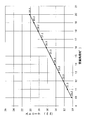
- FIG. 4 is a diagram showing the relationship between the swing angle ⁇ of the plunger pump 52 and the stroke d2 (however, the drive radius is 29.5 mm).
- FIG. 5 is a schematic plan view showing a modified example of the plunger pumps 51 and 52.
- FIG. 6 is a diagram showing the relationship between the swing angle ⁇ of the plunger pump 52 and the stroke d2 in the modified example of the first embodiment (however, the drive radius is 34.5 mm).
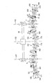
- FIG. 7 is a schematic view showing the structure of the blood purification apparatus 10 according to the second embodiment of the present invention.
- FIG. 8 is a plan view showing the structure of the plunger pumps 51, 52, 53, 54.
- FIG. 9 is a side view showing the structure of the plunger pumps 51, 52, 53, 54.
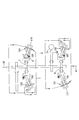
- FIG. 10 is a schematic view showing a modification of the blood purification apparatus 10.
- FIG. 11 is a schematic view showing a modified example of the blood purification device 10.
- FIG. 1 is a schematic explanatory view showing the first embodiment
- FIGS. 2 and 3 are a schematic plan view and a side view showing an embodiment of the plunger pump of FIG.
- the blood purification apparatus 10 includes a blood purification device 1, a blood circuit 2, a blood pump 3, a dialysate line 4 including a fresh dialysate supply line 41 and a used dialysate discharge line 42. , Comprising.
- a pair of plunger pumps 51 and 52 is disposed in the dialysate line 4.
- the blood purifier 1 has a hollow fiber filled inside a container having a first port 81, a second port 82, a third port 83, and a fourth port 84 for inflow and outflow of blood and dialysate.
- the blood is circulated through the inner space of the hollow fiber through the first port 81 and the second port 82, and the dialysate is circulated to the outside of the hollow fiber through the third port 83 and the fourth port 84.
- the blood is dehydrated or reverse filtered.
- the blood circuit 2 is connected to the first port 81 and the second port 82.
- the blood circuit 2 constitutes a blood flow path composed of a resin tube or the like.
- the blood circuit 2 guides blood that has flowed out of the patient's blood vessel to the blood purifier 1, and the blood that has flowed out of the blood purifier 1 has blood flow of the patient. It leads to.
- the blood circuit 2 is provided with a blood pump 3 for generating blood flow in the blood circuit 2.
- a known pump such as a tube pump can be adopted as the blood pump 3.
- the dialysate line 4 is connected to the third port 83 and the fourth port 84 of the blood purifier 1.
- the dialysate line 4 constitutes a dialysate flow path composed of a resin tube or the like.
- a fresh dialysate supply line 41 is connected to the third port 83 of the blood purifier 1, and a spent dialysate discharge line 42 is connected to the fourth port 84.
- the other of the fresh dialysate supply line 41 is connected to a tank storing fresh dialysate, and the other of the used dialysate discharge line 42 is used dialysate. It is connected to a waste tank that stores water.
- the plunger pump 51 is disposed in the fresh dialysate supply line 41.
- the plunger pump 52 is disposed in the spent dialysate discharge line 42.
- the rotation of the pair of plunger pumps 51 and 52 is transmitted from the rotation shaft 50 of the synchronization motor 5 through the drive joints 6 and 7.
- the drive joints 6 and 7 are connected to one end sides of the plungers 61 and 62 of the plunger pumps 51 and 52, respectively.
- the plungers 61 and 62 are driven and transmitted from the drive joints 6 and 7 to reciprocate in the cylinders 71 and 72.
- the axial directions 91 and 92 of the plungers 61 and 62 are inclined (crossed) with respect to the axial directions 93 and 94 of the drive joints 6 and 7, respectively.
- the axial directions 93 and 94 of the drive joints 6 and 7 are the same as the axial direction of the rotary shaft 50. Strokes of the plungers 61 and 62 that reciprocate by driving transmission from the drive joints 6 and 7, respectively, according to an inclination angle ⁇ between the axial directions 91 and 92 of the plungers 61 and 62 and the axial directions 93 and 94 of the drive joints 6 and 7. Is determined. That is, if the inclination angle ⁇ is large, the strokes of the plungers 61 and 62 are large, and if the inclination angle ⁇ is small, the strokes of the plungers 61 and 62 are small.
- Each cylinder 71, 72 is provided with a pair of ports 73, 74 or a pair of ports 75, 76 communicating with the internal space.
- the pair of ports 73 and 74 and the pair of ports 75 and 76 are disposed at positions different from each other by 180 ° with respect to the axial direction of the cylinders 71 and 72, that is, symmetrically.
- the plungers 61 and 62 have a columnar shape that seals the cylinders 71 and 72 in a liquid-tight manner, and their distal ends (the other ends not connected to the drive joints 6 and 7). As for the side), half of the cylindrical shape including the axis is cut out.
- each plunger pump 51, 52 has a mirror-symmetric structure with respect to a plane perpendicular to the rotation shaft 50 of the synchronization motor 5 (a plane perpendicular to the paper surface of FIGS. 1 to 3). I am doing. Specifically, as shown in FIGS. 2 and 3, with respect to a plane 101 that is orthogonal to the rotation axis 50 of the synchronization motor 5 and includes the middle of the direction along the axial directions 93 and 94 of the drive joints 6 and 7. This is a mirror-symmetrical structure.
- the mirror-symmetric structure is that the structures of the plungers 61 and 62 and the cylinders 71 and 72 are mirror-symmetrical, but the axial direction of the plungers 61 and 62 of the plunger pumps 51 and 52 is made by making the angle ⁇ variable.
- the fact that the mirrors 91 and 92 are not mirror-symmetric and that the drive joints 6 and 7 are different from each other in that they are not strictly mirror-symmetric is not excluded from the mirror-symmetric structure.
- the mirror-symmetric structure means that when the pair of plunger pumps 51 and 52 are connected via the drive joints 6 and 7 so as to be rotated by the same synchronization motor 50, the pair of plunger pumps 51 and 52 are connected. As long as it can be maintained that the phase is shifted by 180 °, it is understood that the difference in angle, rotation radius, and the like between the pair of plunger pumps 51 and 52 is allowed.
- the plunger pumps 51 and 52 have a phase difference of 180 ° with respect to the rotation of the drive joints 6 and 7. That is, when the plunger pump 51 discharges fresh dialysate, the plunger pump 52 sucks fresh dialysate, and when the plunger pump 51 sucks fresh dialysate, the plunger pump 51 sucks fresh dialysate. 52 discharges fresh dialysate. Accordingly, the pair of plunger pumps 51 and 52 simultaneously perform the discharge of the fresh dialysate by the plunger pump 51 and the discharge of the fresh dialysate by the plunger pump 52 simultaneously.
- each plunger 61, 62 reciprocates the cylinders 71, 72, whereby the fresh dialysate is discharged from the plunger 51 and the used dialysate is sucked in the plunger 52. Since the constant speed rotation of the synchronizing motor 50 is transmitted as the stroke of each plunger 61, 62 by the drive joints 6, 7, the moving speed of each plunger 61, 62 is sin with respect to the rotational phase of the drive joints 6, 7. It becomes a curve or a cos curve. Accordingly, the discharge amount of fresh dialysate by the plunger 51 and the suction amount of used dialysate by the plunger 52 form a sin curve or a cos curve.
- the fluctuation of the fresh dialysate discharge amount by the plunger 51 and the fluctuation of the suction amount of the used dialysate by the plunger 52 expressed by such a sin curve or cos curve are referred to as “pulsation” in this specification. Since the discharge of the fresh dialysate by the plunger pump 51 and the discharge of the fresh dialysate by the plunger pump 52 are performed simultaneously in synchronism, these “pulsations” are also generated at the same time.
- the pair of plunger pumps 51 and 52 are synchronized so that discharge of fresh dialysate from the plunger pump 51 (discharge step) and suction of used dialysate into the plunger pump 52 (suction step) occur simultaneously.
- the stroke of at least one of the pair of plunger pumps 51 and 52 is variable. Accordingly, the supply of fresh dialysate to the blood purifier 1 and the discharge of spent dialysate from the blood purifier 1 can be performed simultaneously, and the stroke d1 of the plunger pump 51 on the fresh dialysate discharge side is used.
- the stroke is larger than the stroke d2 of the plunger pump 52 on the spent dialysate suction side, reverse filtration can be performed, and the stroke d1 of the plunger pump 51 on the fresh dialysate discharge side is used as the plunger pump 52 on the spent dialysate suction side. If the stroke is smaller than d2, water can be removed.
- the pair of plunger pumps 51, 52 are arranged on the mirror object with respect to the rotation shaft 50 of the synchronization motor 5, for example, as shown in FIGS. 2 and 3.
- a motor that is connected to the synchronization motor 5 located at the center of the rotating shaft 50 via the drive joints 6 and 7 is employed.
- the stroke d1 of the plunger pump 51 is fixed, and the stroke d2 of the plunger pump 52 is made variable.
- the adjustment of the stroke d2 of the plunger pump 52 is performed by rotating the axial direction 91 of the plunger pump 52 and the rotation of the synchronizing motor 5. This is performed by an angle adjusting motor 8 that adjusts a horizontal inclination angle ⁇ between the shaft 94 and the shaft 94.
- the inclination angle ⁇ can be adjusted so that the stroke d2 can be made larger or smaller than the stroke d1.
- Increasing the tilt angle ⁇ increases the stroke, and decreasing the tilt angle ⁇ decreases the stroke.
- the discharge amount was about 24.1 cc / min for a stroke of 1 mm.
- the drive joints 6 and 7 are provided with bearing bearings, and the bearings are mounted on the bearing bearings.
- Each of the bearings is provided with a through hole at a central portion, and one end of each of operating shafts 63 and 64 extending from the plungers 61 and 62 of the plunger pumps 51 and 52 is slidably inserted into the through holes. Yes.
- the action shafts 63 and 64 are fixed so that the other ends are perpendicular to the surfaces of the plungers 61 and 62, and the rotation of the synchronizing motor 5 is transmitted to the drive joints 6 and 7.
- the rotation is transmitted to the plungers 61 and 62 by the action shafts 63 and 64, and strokes d1 and d2 are generated in the inclined plunger pumps 51 and 52, respectively. Accordingly, the plungers 61 and 62 reciprocate according to the strokes d1 and d2 while rotating in the cylinders 71 and 72, respectively.
- the pair of plunger pumps 51 and 52 may be arranged in any manner with respect to the rotation shafts of the drive joints 6 and 7 and the rotation shaft 50 of the synchronization motor 5, but in any case, from the plunger pump 51. In order for the discharge of the fresh dialysate and the suction of the used dialysate to the plunger pump to occur simultaneously, the phases of the plunger pumps 51 and 52 must be shifted by 180 °.
- the pair of plunger pumps 51 and 52 disposed in the dialysate line 4 has a drive radius on the fresh dialysate discharge side of the drive joint 7 on the used dialysate suction side. 6 and the stroke d2 of the plunger pump 52 on the used dialysate suction side may be made variable. If comprised in this way, as shown in FIG.
- valveless plunger pumps may be adopted. In this case, there is no need to prepare a separate valve for extracting air from the dialysate, which is economical.
- the pair of plunger pumps 51, 52 arranged in the dialysate line 4 discharges fresh dialysate from the plunger pump 51 and sucks used dialysate into the plunger pump 52. Since they are synchronized so that they occur at the same time, the supply of fresh dialysate to the blood purifier 1 and the discharge of spent dialysate from the blood purifier 1 can be performed simultaneously.
- the stroke of the plunger pump 52 is made variable, if the stroke d1 of the plunger pump 51 is made larger than the stroke d2 of the plunger pump 52, reverse filtration can be performed, and the stroke d1 of the plunger pump 51 can be set. If the stroke is smaller than the stroke d2 of the plunger pump 52, water can be removed.
- a pair of plunger pumps 51 and 52 are arranged on a mirror object on the rotation shaft 50 of the synchronization motor 5 and are connected via drive joints 6 and 7 so as to be rotated by the same synchronization motor 5. Therefore, the pair of plunger pumps 51 and 52 are in a phase-shifted relationship of 180 ° from the beginning, so that the supply of fresh dialysate to the blood purifier 1 and the use from the blood purifier can be performed without adjusting the phase of both. The spent dialysate can be discharged simultaneously.
- the stroke d1 of the plunger pump 51 is fixed, and the horizontal angle ⁇ of the plunger pump 52 is variable with respect to the rotating shaft 50 of the synchronizing motor 5 by the angle adjusting motor 8, so that the plunger
- the stroke d2 of the plunger pump 52 can be adjusted to be larger or smaller than the stroke d1 of the plunger pump 51 by changing the horizontal angle ⁇ of the pump 52. By adjusting, reverse filtration and water removal can be performed.
- the stroke d2 of the plunger pump 52 can be greatly changed, and the angle adjustment of the plunger pump 52 is easy (smaller inclination). Can respond by angle).
- the back filtration amount and the water removal amount can be set large.
- valveless plunger pumps are used as the plunger pumps 51 and 52, a valve for extracting air from the dialysate can be omitted.
- the plunger pumps 51 and 52 are preferably formed of glass. Moreover, it is preferable that the plungers 61 and 62 and the cylinders 71 and 72 are each manufactured using shrinking. Since the plunger pumps 51 and 52 are made of glass, even if the tolerances of the outer diameters of the plungers 61 and 62 and the inner diameters of the cylinders 71 and 72 are large to some extent, the inside of the plunger pumps 51 and 52 can be secured. The mass productivity of the plunger pumps 51 and 52 is improved. In the plunger pumps 51 and 52, it is preferable that both the plungers 61 and 62 and the cylinders 71 and 72 are made of glass. Plunger pumps 51 and 52 are not limited to glass, and may be formed of other materials such as ceramics. Moreover, the manufacturing method of the plungers 61 and 62 and the cylinders 71 and 72 is not limited to the method using shrinking.
- a rotation step is transmitted from the synchronization motor 50 to the plunger pump 51 to discharge fresh dialysate to the blood purifier 1 through the fresh dialysate supply line 41, and the plunger pump 52 is rotated from the synchronization motor 50 to the plunger pump 52.
- the suction step of sucking the used dialysate from the blood purifier 1 through the used dialysate discharge line 42 is performed simultaneously in synchronism, so that the pair of plunger pumps 51 and 52 are used to supply the blood purifier 1. Supplying fresh dialysate and discharging spent dialysate can be performed simultaneously.
- the drive transmission of the synchronization motor 50 to the plunger pump 51 and the drive transmission of the synchronization motor 50 to the plunger pump 52 are performed with a phase shift of 180 °, the fresh dialysate is purified by the plunger pump 51.
- the phase of the pulsation that occurs when the dialysis fluid is supplied to the blood purifier 1 and the phase of the pulsation that occurs when the used dialysate is discharged from the blood purifier 1 by the plunger pump 52 are synchronized. Pressure stabilizes.
- the blood purifier 1 can perform reverse blood filtration or water removal.
- the blood purification apparatus 11 includes a blood purification device 1, a blood circuit 2 connected to the blood purification device 1, a blood pump 3 that generates a blood flow in the blood circuit 2, and a fresh dialysate supply line 41. And a dialysate line 4 having a used dialysate discharge line 42, plunger pumps 151, 152, 153, 154, and a synchronization motor 5.
- the blood purifier 1 is a container in which a hollow fiber is filled in a container having ports for inflow and outflow of blood and dialysate, and the blood is hollow through the ports for inflow and outflow of blood.
- the dialysate is circulated to the outside of the hollow fiber through the internal space of the yarn and the dialysate inflow and outflow ports, whereby blood is dehydrated or reverse filtered.
- Blood circuit 2 is connected to each port for blood inflow and outflow of blood purifier 1.
- the blood circuit 2 constitutes a blood flow path composed of a resin tube or the like.
- the blood circuit 2 guides blood that has flowed out of the patient's blood vessel to the blood purifier 1, and the blood that has flowed out of the blood purifier 1 has blood flow of the patient. It leads to.
- the blood circuit 2 is provided with a blood pump 3 for generating blood flow in the blood circuit 2.
- a known pump such as a tube pump can be adopted as the blood pump 3.
- a dialysate line 4 is connected to each of the dialysate inflow and outflow ports of the blood purifier 1.
- the dialysate line 4 constitutes a dialysate flow path composed of a resin tube or the like.
- a fresh dialysate supply line 41 is connected to the inflow port of the blood purifier 1, and a spent dialysate discharge line 42 is connected to the outflow port.
- the other of the fresh dialysate supply line 41 is connected to a tank storing fresh dialysate, and the other of the used dialysate discharge line 42 is used dialysate. It is connected to a waste tank that stores water.
- the fresh dialysate supply line 41 a part of the line between the blood purifier 1 and the tank (not shown) has a parallel structure divided into two hands.
- a pair of plunger pumps 151 and 152 are arranged on each of the parallel lines.
- the rotation of the pair of plunger pumps 151 and 152 is transmitted from the rotation shaft 50 of the synchronization motor 5 via the drive joint 6 (an example of a first drive joint).
- the drive joint 6 is connected to one end side of each plunger 161, 162 of the plunger pump 151, 152, respectively.
- the plungers 161 and 162 are driven and transmitted from the drive joint 6 to reciprocate in the cylinders 171 and 172.
- the axial directions 191 of the plungers 161 and 162 are inclined (crossed) with respect to the axial direction 193 of the drive joint 6.
- the strokes of the plungers 161 and 162 that reciprocate by being transmitted from the drive joint 6 are determined by the inclination angle ⁇ between the axial direction 191 of the plungers 161 and 162 and the axial direction 193 of the drive joint 6. That is, if the inclination angle ⁇ is large, the strokes of the plungers 161 and 162 are large, and if the inclination angle ⁇ is small, the strokes of the plungers 161 and 162 are small.
- Each cylinder 171 and 172 is provided with a pair of ports communicating with the internal space.
- the pair of ports are disposed at positions different from each other by 180 degrees with respect to the axial direction of the cylinders 171 and 172, that is, axially symmetrical.
- the plungers 161 and 162 have a columnar shape that seals the cylinders 171 and 172 in a liquid-tight manner, and the tip side thereof (the other end side not connected to the drive joint 6). The half of the cylindrical shape including the axis is cut out.
- one plunger pump 151, 152 has a mirror-symmetric structure with respect to a plane perpendicular to the rotation shaft 50 of the synchronization motor 5 (a plane perpendicular to the paper surface of FIGS. 7 to 9). I am doing. Specifically, as shown in FIGS. 7 and 8, the structure is mirror-symmetric with respect to a plane 101 that is orthogonal to the rotation shaft 50 of the synchronization motor 5 and includes the center of the drive joint 6 in the axial direction. Therefore, the angle at which the plungers 161 and 162 are inclined with respect to the drive joint 6 and the positions of the ports of the cylinders 171 and 172 are mirror-symmetric.
- the plunger pumps 151 and 152 have a phase difference of 180 degrees with respect to the rotation of the drive joint 6. That is, when the plunger pump 151 discharges fresh dialysate, the plunger pump 152 sucks fresh dialysate, and when the plunger pump 151 sucks fresh dialysate, the plunger pump 151 sucks fresh dialysate. 152 discharges fresh dialysate. Accordingly, the pair of plunger pumps 151 and 152 alternately and continuously discharges the fresh dialysate discharged from the plunger pump 151 and the fresh dialysate discharged from the plunger pump 152.
- the spent dialysate discharge line 42 a part of the line between the blood purifier 1 and the waste tank (not shown) has a parallel structure divided into two hands.
- a pair of plunger pumps 153 and 154 are arranged in each of the parallel lines.
- the rotation of the pair of plunger pumps 153 and 154 is transmitted from the rotation shaft 50 of the synchronization motor 5 via the drive joint 7 (an example of a second drive joint).
- the drive joint 7 is connected to one end side of each plunger 163, 164 of the plunger pump 153, 154, respectively.
- the plungers 163 and 164 are driven and transmitted from the drive joint 7 to reciprocate in the cylinders 173 and 174.
- the axial direction 192 of the plungers 163 and 164 is inclined (crossed) with respect to the axial direction 194 of the drive joint 7.
- the strokes of the plungers 163 and 164 reciprocated by driving transmission from the drive joint 7 are determined by the inclination angle ⁇ between the axial direction 192 of the plungers 163 and 164 and the axial direction 194 of the drive joint 7. That is, if the inclination angle ⁇ is large, the strokes of the plungers 163 and 164 are large, and if the inclination angle ⁇ is small, the strokes of the plungers 163 and 164 are small.
- the plungers 161, 162, and 163 of the plunger pumps 151, 152, and 153 have a fixed inclination angle ⁇ with respect to the drive joint 6 or the drive joint 7, but the plunger 164 of the plunger pump 154 has an inclination angle ⁇ with respect to the drive joint 7. Is variable.
- the inclination angle ⁇ of the plunger 164 is adjusted by driving the angle adjustment motor 8.
- the drive joint 7 is provided with a bearing bearing, and the bearing is mounted on the bearing bearing.
- the bearings are each provided with a through hole in the center portion, and one end of an operating shaft extending from each of the plungers 163 and 164 of the plunger pumps 153 and 154 is slidably inserted into the through holes.
- This action shaft is fixed so that the other end is perpendicular to the surfaces of the plungers 163 and 164, and the rotation of the rotation shaft 50 of the synchronization motor 5 is transferred to the plungers 163 and 164 via the drive joint 7 and the action shaft.
- the strokes d1 and d2 are generated in the plunger pumps 153 and 154 in accordance with the inclination angle ⁇ .
- the plungers 163 and 164 reciprocate in the strokes d1 and d2 while rotating in the cylinders 173 and 174, respectively.
- the drive transmission from the drive joint 6 to the plunger pumps 151 and 152 is the same.
- Each cylinder 173, 174 is provided with a pair of ports leading to the internal space.
- the pair of ports are disposed at positions different from each other by 180 degrees with respect to the axial direction of the cylinders 173 and 174, that is, symmetrically.
- the plungers 163 and 164 have a columnar shape that liquid-tightly seals the cylinders 173 and 174, and the tip end side (the other end side not connected to the drive joint 7). The half of the cylindrical shape including the axis is cut out.
- one plunger pump 153, 154 has a mirror-symmetric structure with respect to a plane perpendicular to the rotation shaft 50 of the synchronization motor 5 (a plane perpendicular to the paper surface of FIGS. 7 to 9). I am doing. Specifically, as shown in FIGS. 7 and 8, the structure is mirror-symmetric with respect to a plane 102 that is orthogonal to the rotation axis 50 of the synchronization motor 5 and includes the center in the axial direction of the drive joint 7. Therefore, the angle at which the plungers 163 and 164 are inclined with respect to the drive joint 7 and the positions of the ports of the cylinders 173 and 174 are mirror-symmetric.
- the plunger pumps 153 and 154 have a phase difference of 180 degrees with respect to the rotation of the drive joint 7. That is, when the plunger pump 153 is sucking the used dialysate, the plunger pump 154 is discharging the used dialysate, and when the plunger pump 153 is discharging the used dialysate. The plunger pump 154 sucks the used dialysate. As a result, the pair of plunger pumps 153 and 154 alternately and continuously sucks the used dialysate by the plunger pump 153 and sucks the used dialysate by the plunger pump 154.
- the pair of plunger pumps 151 and 152 and the pair of plunger pumps 153 and 154 are planes orthogonal to the rotation shaft 50 of the synchronization motor 5 (perpendicular to the paper surface of FIGS. 7 to 9).
- the plane is mirror-symmetrical.
- the structure is mirror-symmetric with respect to the plane 103 including the center of the rotation shaft 50 of the synchronization motor 5. Therefore, the supply of fresh dialysate to the blood purifier 1 by the plunger pumps 151 and 152 and the discharge of the used dialysate from the blood purifier 1 by the plunger pumps 153 and 154 are performed simultaneously and synchronously.
- the cylinders 171, 172, 173, 174 of the plunger pumps 151, 152, 153, 154 and the structures of the plungers 161, 162, 163, 164 are equivalent, so the inclination of each plunger 161, 162, 163, 164 If the angle ⁇ is the same, the amount of fresh dialysate discharged or the amount of used dialysate sucked by the plunger pumps 151, 152, 153, 154 becomes the same. However, by making the stroke d2 of the plunger 164 of the plunger pump 154 variable, the amount of the used dialysate sucked per one stroke d2 by the plunger pump 154 is changed to the fresh dialysate by the other plunger pumps 151, 152, 153.
- the stroke d2 of the plunger pump 154 is made larger than the stroke d1 of the plungers 161 and 162 on the fresh dialysate discharge side, blood can be dehydrated in the blood purifier 1, and the stroke d2 can be made smaller than the stroke d1.
- the blood purifier 1 can perform reverse filtration of blood.
- the stroke d2 of the plunger pump 154 is made variable among the pair of plunger pumps 153 and 154 of the spent dialysate discharge line 42 arranged in parallel, the plunger pump 151 provided in the fresh dialysate supply line 41 If the stroke d2 of the plunger pump 154 provided in the spent dialysate discharge line 42 is adjusted to be smaller than the stroke d1 of 152, the blood purifier 1 can perform reverse blood filtration. Further, if the stroke d2 of the plunger pump 154 provided in the used dialysate discharge line is adjusted to be larger than the stroke d1 of the plunger pumps 151 and 152 provided in the fresh dialysate supply line 41, the blood purifier In 1, blood can be dehydrated.
- a pair of plunger pumps 151 and 152 are arranged mirror-symmetrically with respect to the plane 101 orthogonal to the rotation shaft 50 of the synchronization motor 5 and are connected to the rotation shaft 50 of the synchronization motor 5 via the drive joint 6. Therefore, the pair of plunger pumps 151 and 152 have a relationship that the phases are shifted by 180 degrees. Accordingly, the fresh dialysate can be continuously and alternately supplied to the blood purifier 1 without adjusting the phases of the pair of plunger pumps 151 and 152.
- a pair of plunger pumps 153 and 154 are arranged in mirror symmetry with respect to the plane 102 orthogonal to the rotation shaft 50 of the synchronization motor 5 and are connected to the rotation shaft 50 of the synchronization motor 5 via the drive joint 7. Therefore, the pair of plunger pumps 153 and 154 are in a relationship in which phases are shifted by 180 degrees. Therefore, the used dialysate can be discharged continuously and alternately from the blood purifier 1 without adjusting the phase of the pair of plunger pumps 153 and 154.
- the pair of plunger pumps 151 and 152 provided in the fresh dialysate supply line 41 and the pair of plunger pumps 153 and 154 provided in the used dialysate discharge line 42 are the rotation shafts of the synchronization motor 5. 50, the pair of plunger pumps 151 and 152 and the pair of plunger pumps 153 and 154 are in a phase-shifted relationship of 180 degrees. Therefore, the supply of fresh dialysate to the blood purifier 1 and the discharge of used dialysate from the blood purifier without adjusting the phase of the pair of plunger pumps 151, 152 and the pair of plunger pumps 153, 154. Can be performed simultaneously.
- the stroke d2 of the plunger pump 154 provided in the used dialysate discharge line 42 can be adjusted by adjusting the inclination angle ⁇ , the stroke 161 of the plunger pump 154 is changed to the plunger 161 on the fresh dialysate discharge side. 162, the blood purifier 1 can perform blood dehydration, and the stroke d2 smaller than the stroke d1 can perform blood reverse filtration in the blood purifier 1.
- the pair of plunger pumps 151 and 152 and the pair of plunger pumps 153 and 154 are not necessarily mirror-symmetrical with respect to the plane 103 orthogonal to the rotation axis 50 of the synchronization motor 5. Can be in a relationship of 180 degrees out of phase.
- the drive joint 6 and the drive joint 7 are not arranged on one rotational axis, and are offset to different positions with respect to the rotational axis 50 of the synchronization motor 5.
- the drive joint 6 and the drive joint 7 are arranged on one rotational axis, even if the drive joint 6 and the drive joint 7 are arranged in a mirror symmetry with respect to the plane 103, the pair of plunger pumps 151, 152 and the pair Even if the phases of the plunger pumps 153 and 154 are not adjusted, the supply of fresh dialysate to the blood purifier 1 and the discharge of used dialysate from the blood purifier can be performed simultaneously.
- the blood purification device 11 can be downsized. Can be realized.
- the pair of plunger pumps 151 and 152 and the pair of plunger pumps 153 and 154 are arranged completely in parallel, so that the contribution to downsizing of the blood purification apparatus 11 is significant. Become.
Landscapes
- Health & Medical Sciences (AREA)
- Heart & Thoracic Surgery (AREA)
- Engineering & Computer Science (AREA)
- Urology & Nephrology (AREA)
- Animal Behavior & Ethology (AREA)
- Life Sciences & Earth Sciences (AREA)
- Veterinary Medicine (AREA)
- Public Health (AREA)
- General Health & Medical Sciences (AREA)
- Hematology (AREA)
- Vascular Medicine (AREA)
- Anesthesiology (AREA)
- Biomedical Technology (AREA)
- Emergency Medicine (AREA)
- General Engineering & Computer Science (AREA)
- Mechanical Engineering (AREA)
- Fluid Mechanics (AREA)
- Physics & Mathematics (AREA)
- General Physics & Mathematics (AREA)
- External Artificial Organs (AREA)
Abstract
血液浄化器(1)と、血液回路(2)と、血液ポンプ(3)と、新鮮透析液供給ライン(41)と使用済透析液排出ライン(42)からなる透析液ライン(4)と、を含んだ血液浄化装置において、前記透析液ライン(4)に一対のプランジャポンプ(51、52)を配設する。当該一対のプランジャポンプ(51、52)は、一方のプランジャポンプ(51)からの新鮮透析液の吐出と、他方のプランジャポンプ(52)への使用済透析液の吸込が同時に起こるように同期されているとともに、一対のプランジャポンプ(51、52)の少なくとも一方のストロークが可変にされている。
Description
本発明は、透析液ラインに一対のプランジャポンプが配設されてなる血液浄化装置、及び血液浄化器へ透析液を流通する方法に関する。より詳しくは、本発明は、プランジャポンプを利用して、血液浄化器に対して、脈動の無い新鮮透析液の供給を可能とする血液浄化装置、及び血液浄化器へ透析液を流通する方法に関する。
従来、腎不全の患者や、術後の薬液注入によって水分過多症になった患者などの重篤な状態を改善するために、血液浄化装置を使用する血液透析や血液濾過が行われている。血液浄化器への新鮮透析液の供給、及び血液浄化器からの使用済透析液の排出をするために、従来、新鮮透析液の供給と使用済透析液の排出とを同時に行える往復動ポンプを利用したものが知られている(特許文献1、特許文献2)。
また、往復動ポンプとして透析液中の空気を抜くためのバルブを必要としないプランジャポンプも提案されている(特許文献3、特許文献4)。
特許文献1,2に記載された往復動ポンプは、除水や逆濾過を行うために、別途除水ポンプや加圧ポンプを必要とするので、コストが高くなるという問題があった。特許文献3,4に記載された往復動ポンプは、新鮮透析液の供給と使用済透析液の排出とを同時に行えるものではない。したがって、これらを同時に行うようにするための改良が必要である。また、血液浄化装置に対して、脈動の無い新鮮透析液の供給を可能とするプランジャポンプが望まれる。
本発明は、上記事情に鑑みてなされたもので、透析液ラインにおいて、新鮮透析液の供給と使用済透析液の排出を同時に行う手段を提供することを目的とする。
また、本発明の他の目的は、透析液ラインに、新鮮透析液の供給と使用済透析液の排出とを同時に行い、血液浄化器に対して脈動の無い新鮮透析液の供給が可能な血液浄化装置を提供することにある。
(1) 本発明の血液浄化装置は、血液浄化器と、血液回路と、血液ポンプと、新鮮透析液供給ラインと使用済透析液排出ラインからなる透析液ラインと、を含んでなる血液浄化装置において、前記透析液ラインに一対のプランジャポンプが配設されており、この一対のプランジャポンプは、一方のプランジャポンプからの新鮮透析液の吐出と、他方のプランジャポンプへの使用済透析液の吸込が同時に起こるように同期されるとともに、この一対のプランジャポンプの少なくとも一方のストロークが可変にされてなることを特徴とする。
(2) また、透析液ラインに配設される一対のプランジャポンプとしては、具体的には、一対のプランジャポンプが、同期用モータの回転軸に関して鏡対象に配設されるとともに、この回転軸の中心部に位置する前記同期用モータとドライブ継ぎ手を介してそれぞれ接続されてなるものが採用される。
(3) また、新鮮透析液吐出側のプランジャポンプのストロークが固定されるとともに、使用済透析液吸込側のプランジャポンプのストロークの調節が、このプランジャポンプと同期用モータの回転軸との間の水平方向の傾斜角度を調節する角度調節モータによって行われるようにされていてもよい。
(4) また、透析液ラインに配設される一対のプランジャポンプとしては、使用済透析液吸込側のドライブ継ぎ手の回転半径が新鮮透析液吐出側のドライブ継ぎ手の回転半径より大きくされるとともに、この使用済透析液吸込側のプランジャポンプのストロークが可変にされてなるものであってもよい。
(5) また、本発明に係る血液浄化装置は、血液浄化器と、当該血液浄化器に接続された血液回路と、当該血液回路において血流を発生させるための血液ポンプと、当該血液浄化器に対してそれぞれ接続された新鮮透析液供給ライン及び使用済透析液排出ラインを有する透析液ラインと、当該新鮮透析液供給ライン及び当該使用済透析液排出ラインにそれぞれ設けられて一対をなすプランジャポンプと、を具備する。上記新鮮透析液供給ラインに設けられたプランジャポンプによる新鮮透析液の吐出と、上記使用済透析液排出ラインに設けられたプランジャポンプによる使用済透析液の吸込みと、が同時に行われるように同期されている。
(6) また、上記新鮮透析液供給ライン及び上記使用済透析液排出ラインにそれぞれ設けられたプランジャポンプのうちの少なくとも一方のプランジャポンプのストロークが可変であってもよい。
(7) また、同期用モータと、上記同期用モータから駆動力を付与されて回転するドライブ継ぎ手と、を更に備え、上記一対のプランジャポンプは、上記同期用モータの回転軸と直交する平面に対して鏡対称に配置されており、上記ドライブ継ぎ手により上記同期用モータに接続されていてもよい。
(8) また、上記一対のプランジャポンプのうちストロークが可変のプランジャポンプは、プランジャの軸が上記同期用モータの回転軸に対して傾斜する角度を調節可能なものであってもよい。
(9) また、上記プランジャの軸の傾斜角度を変化させる角度調節モータを更に具備してもよい。
(10) また、上記使用済透析液排出ラインに設けられたプランジャポンプのストロークが可変であってもよい。
(11) また、使用済透析液吸込側の前記ドライブ継ぎ手の回転半径が新鮮透析液吐出側の前記ドライブ継ぎ手の回転半径より大きくてもよい。
(12) また、プランジャポンプは、バルブレスプランジャポンプであってもよい。
(13) また、透析液ラインに並列に、位相を180°ずらしたもう一対のプランジャポンプが配設されていてもよい。
(14) 本発明は、血液浄化器に対してそれぞれ接続された新鮮透析液供給ライン及び使用済透析液排出ラインにおいて、それぞれに設けられた第1プランジャポンプ及び第2プランジャポンプを用いて上記血液浄化器へ透析液を流通させる方法に関する。血液浄化器への透析液の流通方法は、上記第1プランジャポンプに同期用モータから回転駆動を伝達して上記新鮮透析液供給ラインを通じて上記血液浄化器へ新鮮透析液の吐出する吐出ステップと、上記第2プランジャポンプに上記同期用モータから回転駆動を伝達して上記使用済透析液排出ラインを通じて上記血液浄化器から使用済透析液を吸込む吸込ステップと、を含み、上記吐出ステップと上記ステップとを同期させて同時に行う。
これにより、プランジャポンプを用いて血液浄化器へ新鮮透析液の供給と使用済透析液の排出とを同時に行うことができる。
(15) 好ましくは、上記吐出ステップにおける上記第1プランジャポンプへの上記同期用モータの駆動伝達と、上記吸込ステップにおける上記第2プランジャポンプへの上記同期用モータの駆動伝達とを、位相を180°ずらして行う。
これにより、第1プランジャポンプによって新鮮透析液を血液浄化器へ供給する際に生ずる脈動の位相と、第2プランジャポンプによって使用済透析液を血液浄化器から排出する際に生ずる脈動の位相と、が同期して、血液浄化器内における透析液の圧力が安定する。
(16) 好ましくは、上記吐出ステップにおける上記第1プランジャポンプのストロークと、上記吸込ステップにおける上記第2プランジャポンプのストロークとを異ならせる。
これにより、血液浄化器において血液の逆濾過又は除水を行うことができる。
(17) 本発明に係る血液浄化装置は、血液浄化器と、当該血液浄化器に接続された血液回路と、当該血液回路において血流を発生させるための血液ポンプと、当該血液浄化器に対してそれぞれ少なくとも一部が並列に接続された新鮮透析液供給ライン及び使用済透析液排出ラインを有する透析液ラインと、並列の新鮮透析液供給ライン及び並列の使用済透析液排出ラインにおいてそれぞれ一対が設けられたプランジャポンプと、を具備する。上記並列の新鮮透析液供給ラインにそれぞれ設けられた一対のプランジャポンプは、一対のうちの一方のプランジャポンプによる新鮮透析液の吐出と、他方のプランジャポンプによる新鮮透析液の吐出と、を交互に連続して行うものである。上記並列の使用済透析液排出ラインに設けられた一対のプランジャポンプは、一対のうちの一方のプランジャポンプによる使用済透析液の吸込みと、他方のプランジャポンプによる使用済透析液の吸込みと、を交互に連続して行うものである。上記新鮮透析液供給ラインに設けられた一対のプランジャポンプによる新鮮透析液の吐出と、上記使用済透析液排出ラインに設けられた一対のプランジャポンプによる使用済透析液の吸込みと、が同時に行われるように同期されている。
並列された新鮮透析液供給ラインの一対のプランジャポンプにおいて、一方のプランジャポンプからの新鮮透析液の吐出と、他方のプランジャポンプからの新鮮透析液の吐出とが交互に連続して行われ、また、並列された使用済透析液排出ラインの一対のプランジャポンプにおいて、一方のプランジャポンプへの使用済透析液の吸込みと、他方のプランジャポンプへの使用済透析液の吸込みとが交互に連続して行われ、かつ新鮮透析液の吐出と使用済透析液の吸込とが同時に起こるように同期されているので、血液浄化器への新鮮透析液の供給と、血液浄化器からの使用済透析液の排出とが同時に行われる。これにより、血液浄化器に対して、脈動の無い新鮮透析液が供給される。
(18) 好ましくは、上記並列の使用済透析液排出ラインに設けられた一対のプランジャポンプのうちの少なくとも一方のプランジャポンプのストロークが可変である。
これにより、新鮮透析液供給ラインに設けられたプランジャポンプのストロークより、使用済透析液排出ラインに設けられたプランジャポンプのストロークが小さくなるように調節すれば、血液浄化器において逆濾過を行うことができる。また、新鮮透析液供給ラインに設けられたプランジャポンプのストロークより、使用済透析液排出ラインに設けられたプランジャポンプのストロークが大きくなるように調節すれば、血液浄化器において除水を行うことができる。
(19) 好ましくは、同期用モータと、上記同期用モータから駆動力を付与されて回転する第1ドライブ継ぎ手と、を更に備え、上記並列の新鮮透析液供給ラインに設けられた一対のプランジャポンプは、上記同期用モータの回転軸と直交する平面に対して鏡対称に配置されており、上記第1ドライブ継ぎ手により上記同期用モータに接続されている。
一対のプランジャポンプが、同期用モータの回転軸と直交する平面に関して鏡対称に配設され、同期用モータの回転軸と第1ドライブ継ぎ手を介してそれぞれ接続されているので、一対のプランジャポンプは位相が180度ずれた関係となる。したがって、一対のプランジャポンプの位相を調整しなくても、血液浄化器への新鮮透析液の供給を連続して交互に行うことができる。
(20) 好ましくは、同期用モータと、上記同期用モータから駆動力を付与されて回転する第2ドライブ継ぎ手と、を更に備え、上記並列の使用済透析液排出ラインに設けられた一対のプランジャポンプは、上記同期用モータの回転軸と直交する平面に対して鏡対称に配置されており、上記第2ドライブ継ぎ手により上記同期用モータに接続されている。
一対のプランジャポンプが、同期用モータの回転軸と直交する平面に関して鏡対称に配設され、同期用モータの回転軸と第2ドライブ継ぎ手を介してそれぞれ接続されているので、一対のプランジャポンプは位相が180度ずれた関係となる。したがって、一対のプランジャポンプの位相を調整しなくても、血液浄化器からの使用済透析液の排出を連続して交互に行うことができる。
(21) 好ましくは、上記並列の新鮮透析液供給ラインに設けられた一対のプランジャポンプと、上記並列の使用済透析液排出ラインに設けられた一対のプランジャポンプと、は、上記同期用モータの回転軸と直交する平面に対して鏡対称に配置されている。
これにより、一対のプランジャポンプ同士は位相が180度ずれた関係となる。したがって、一対のプランジャポンプ同士の位相を調整しなくても、血液浄化器への新鮮透析液の供給と血液浄化器からの使用済透析液の排出とを同時に行うことができる。
(22) 好ましくは、同期用モータと、上記同期用モータから駆動力を付与されて回転する第2ドライブ継ぎ手と、を更に備え、上記並列の使用済透析液排出ラインに設けられた一対のプランジャポンプは、上記第2ドライブ継ぎ手により上記同期用モータに接続されており、上記並列の使用済透析液排出ラインにそれぞれ設けられた一対のプランジャポンプのうちストロークが可変のプランジャポンプは、プランジャの軸が上記同期用モータの回転軸に対して傾斜する角度を調節可能なものである。
使用済透析液排出ラインに設けられたプランジャポンプのストロークの調節を、該プランジャポンプと同期用モータの回転軸との傾斜角度を調節することにより行うことができる。
(23) 好ましくは、上記プランジャの軸の傾斜角度を変化させる角度調節モータを更に具備する。
これにより、プランジャポンプが駆動されているときにもプランジャの軸の傾斜角度を調節することができる。
以上、一般的に本発明を記述したが、より一層の理解は、いくつかの特定の実施例を参照することによって得ることができる。これらの実施例は、本明細書に例示の目的のためにのみ提供されるものであり、他の旨が特定されない限り、限定的なものではない。
本発明によれば、血液浄化器への新鮮透析液の供給と使用済透析液の排出を同時に行うことができる。
また、除水や逆濾過を行える一対のプランジャポンプが配設されてなる血液浄化装置が実現される。
また、透析液ラインに、新鮮透析液の供給と使用済透析液の排出とを同時に行い、血液浄化器に対して脈動の無い新鮮透析液を供給することができる。
以下、本発明をさらに具体的にするために、本発明の実施態様について、図面を用いて説明する。
[第1実施形態]
図1には第1実施形態を示す概略説明図が示されており、図2および図3には図1のプランジャポンプの一実施例を示す概略の平面図および側面図が示されている。
図1には第1実施形態を示す概略説明図が示されており、図2および図3には図1のプランジャポンプの一実施例を示す概略の平面図および側面図が示されている。
血液浄化装置10は、図1に示すように、血液浄化器1と、血液回路2と、血液ポンプ3と、新鮮透析液供給ライン41と使用済透析液排出ライン42からなる透析液ライン4と、を含んでなる。透析液ライン4には一対のプランジャポンプ51、52が配設されている。
血液浄化器1は、血液及び透析液の流入用及び流出用の第1ポート81、第2ポート82、第3ポート83、及び第4ポート84を備えた容器の内部に中空糸が充填されたものであり、第1ポート81及び第2ポート82を通じて血液が中空糸の内部空間を流通され、かつ第3ポート83及び第4ポート84を通じて中空糸の外側に透析液が流通されることにより、血液の除水又は逆濾過を行うものである。
第1ポート81及び第2ポート82には、血液回路2が接続されている。血液回路2は、樹脂チューブなどからなる血液の流路を構成するものであり、患者の血管から流出した血液を血液浄化器1へ導き、また、血液浄化器1から流出した血液を患者の血管へ導くものである。血液回路2には、血液回路2において血流を発生させるための血液ポンプ3が設けられている。血液ポンプ3には、チューブポンプなどの公知のものが採用され得る。
血液浄化器1の第3ポート83及び第4ポート84には、透析液ライン4が接続されている。透析液ライン4は、樹脂チューブなどからなる透析液の流路を構成するものである。血液浄化器1の第3ポート83には、新鮮透析液供給ライン41が接続されており、第4ポート84には、使用済透析液排出ライン42が接続されている。各図には現れていないが、新鮮透析液供給ライン41の他方は、新鮮透析液が貯留されたタンクに接続されており、また、使用済透析液排出ライン42の他方は、使用済透析液を貯留する廃タンクに接続されている。
プランジャポンプ51は、新鮮透析液供給ライン41に配設されている。プランジャポンプ52は、使用済透析液排出ライン42に配設されている。
一対のプランジャポンプ51,52は、同期用モータ5の回転軸50からドライブ継ぎ手6,7を介して回転が伝達されている。ドライブ継ぎ手6,7は、プランジャポンプ51,52の各プランジャ61,62の一端側とそれぞれ接続されている。各プランジャ61,62は、ドライブ継ぎ手6,7から駆動伝達されて、各シリンダ71,72内を往復動する。
プランジャ61,62の軸方向91,92は、ドライブ継ぎ手6,7の軸方向93,94に対してそれぞれ傾斜(交差)している。なお、本実施形態では、ドライブ継ぎ手6,7の軸方向93,94は、回転軸50の軸方向と同一である。プランジャ61,62の軸方向91,92と、ドライブ継ぎ手6,7の軸方向93,94との傾斜角度θによって、ドライブ継ぎ手6,7からそれぞれ駆動伝達されて往復動するプランジャ61,62のストロークが決定される。すなわち、傾斜角度θが大きければプランジャ61,62のストロークが大きくなり、傾斜角度θが小さければプランジャ61,62のストロークが小さくなる。
各シリンダ71,72には、内部空間に通じた一対のポート73,74又は一対のポート75,76がそれぞれ設けられている。一対のポート73,74及び一対のポート75,76は、シリンダ71,72の軸方向に対して180°異なる位置に、すなわち軸対称に配置されている。各図には詳細に現れていないが、プランジャ61,62は、各シリンダ71,72を液密に封止する円柱形状であり、その先端側(ドライブ継ぎ手6,7と接続されていない他端側)は、円柱形状のうち軸線を含む半分が切り欠かれている。この切り欠かれた部分がシリンダ71,72において回転することにより、シリンダ71,72の各一対のポート73,74又は一対のポート75,76のうちの一方がプランジャ61,62によって封止され、他方が切り欠かれた部分によって開放される。
図1~3に示されるように、一つのプランジャポンプ51,52は、同期用モータ5の回転軸50と直交する平面(図1~3の紙面と直交する平面)に対して鏡対称の構造をなしている。詳細には、図2,3に示されるように、同期用モータ5の回転軸50と直交し、かつドライブ継ぎ手6,7の軸方向93,94に沿った方向の中間を含む平面101に対して鏡対称の構造である。したがって、角度θが同一であるときのプランジャ61,62がドライブ継ぎ手6,7に対して傾斜する角度や、シリンダ71,72の各ポート73,74,75,76の位置などが鏡対称である。
なお、鏡対称の構造とは、プランジャ61,62及びシリンダ71,72の構造が鏡対称であるが、角度θが可変にされることによって、プランジャポンプ51,52のプランジャ61,62の軸方向91,92が鏡対称とならないことや、ドライブ継ぎ手6,7の回転半径が異なることにより厳密な鏡対称とならないことは、鏡対称の構造から除かれないものである。つまり、鏡対称の構造とは、一対のプランジャポンプ51,52が同じ同期用モータ50で回転されるようにドライブ継ぎ手6,7を介して接続されているときに、一対のプランジャポンプ51,52の位相が180°ずれた関係となることが維持できる限り、角度や回転半径などが一対のプランジャポンプ51,52において相違することは許容されていると解する。
これにより、プランジャポンプ51,52は、ドライブ継ぎ手6,7の回転に対して180°位相が異なる。つまり、プランジャポンプ51が新鮮透析液の吐出を行っているときには、プランジャポンプ52は新鮮透析液の吸い込みを行っており、また、プランジャポンプ51が新鮮透析液の吸い込みを行っているときには、プランジャポンプ52は新鮮透析液の吐出を行っている。これにより、一対のプランジャポンプ51,52は、プランジャポンプ51による新鮮透析液の吐出と、プランジャポンプ52による新鮮透析液の吐出と、を同期して同時に行う。
各プランジャポンプ51,52において、各プランジャ61,62がそれぞれシリンダ71,72を往復動することにより、プランジャ51では新鮮透析液が吐出され、プランジャ52では使用済透析液が吸い込まれる。同期用モータ50の等速回転がドライブ継ぎ手6,7により各プランジャ61,62のストロークとして伝達されるので、各プランジャ61,62の移動速度は、ドライブ継ぎ手6,7の回転位相に対してsin曲線又はcos曲線となる。したがって、プランジャ51による新鮮透析液の吐出量、及びプランジャ52による使用済透析液の吸込み量は、sin曲線又はcos曲線をなす。このようなsin曲線又はcos曲線により現されるプランジャ51による新鮮透析液の吐出量の変動、及びプランジャ52による使用済透析液の吸込み量の変動を本明細書において「脈動」と称する。プランジャポンプ51による新鮮透析液の吐出と、プランジャポンプ52による新鮮透析液の吐出と、が同期して同時に行われるので、これらの「脈動」も同期して同時に生ずる。
一対のプランジャポンプ51、52は、プランジャポンプ51からの新鮮透析液の吐出(吐出ステップ)と、プランジャポンプ52への使用済透析液の吸込(吸込ステップ)とが同時に起こるように同期されており、この一対のプランジャポンプ51、52の少なくとも一方のストロークが可変にされている。従って、血液浄化器1への新鮮透析液の供給と、血液浄化器1からの使用済透析液の排出を同時に行うことができ、また、新鮮透析液吐出側のプランジャポンプ51のストロークd1を使用済透析液吸込側のプランジャポンプ52のストロークd2より大きくすれば、逆濾過を行うことができ、また新鮮透析液吐出側のプランジャポンプ51のストロークd1を使用済透析液吸込側のプランジャポンプ52のストロークd2より小さくすれば、除水を行うことができるようになっている。
そして、具体的には、一対のプランジャポンプ51、52は、例えば図2、図3に示すように、一対のプランジャポンプ51、52が、同期用モータ5の回転軸50に関して鏡対象に配設されるとともに、この回転軸50の中心部に位置する同期用モータ5とドライブ継ぎ手6,7を介してそれぞれ接続されてなるものが採用されている。
また、プランジャポンプ51のストロークd1が固定されるとともに、プランジャポンプ52のストロークd2が可変にされ、このプランジャポンプ52のストロークd2の調節は、プランジャポンプ52の軸方向91と同期用モータ5の回転軸94との間の水平方向の傾斜角度θを調節する角度調節モータ8によって行われるようにされている。ここで、ストロークd2は、図4に示すように、ストロークd1より大きくしたり、小さくしたりすることができるように傾斜角度θを調節することができる。傾斜角度θを大きくすればストロークが大きくなり、傾斜角度θを小さくすればストロークが小さくなる。因みに、プランジャ径16mmの時のプランジャポンプのストロークと吐出量の関係を求めたところ、ストローク1mmについて吐出量は凡そ24.1cc/分だった。
ここで、プランジャポンプの傾斜角度の調節機能について、もう少し詳しく説明すると以下のようになる。すなわち、ドライブ継ぎ手6,7にはベアリング軸受けが設けられており、このベアリング軸受けにはベアリングが装着されている。このベアリングには、それぞれ中央部分に貫通孔が設けられており、この貫通孔にはプランジャポンプ51、52のプランジャ61,62からそれぞれ延びる作用軸63,64の一端が摺動自在に挿通されている。この作用軸63,64は、その他端がプランジャ61,62の表面に垂直になるように固定されており、同期用モータ5の回転はドライブ継ぎ手6,7に伝わり、このドライブ継ぎ手6,7の回転が作用軸63,64によってプランジャ61,62に伝わり、傾斜されたプランジャポンプ51、52にストロークd1、d2が生ずるようになっている。従って、プランジャ61,62は、それぞれシリンダ71,72内を回転しながらストロークd1、d2に応じて往復動する様になっている。
尚、一対のプランジャポンプ51、52は、ドライブ継ぎ手6,7の回転軸や、同期用モータ5の回転軸50に関してどのように配設されていてもよいが、何れにせよ、プランジャポンプ51からの新鮮透析液の吐出とプランジャポンプへの使用済透析液の吸込が同時に起こるようにするためには、プランジャポンプ51と52の位相は180°ずらしておく必要がある。
また、透析液ライン4に配設される一対のプランジャポンプ51、52としては、図5に示すように、使用済透析液吸込側のドライブ継ぎ手7の回転半径が新鮮透析液吐出側のドライブ継ぎ手6の回転半径より大きくされるとともに、この使用済透析液吸込側のプランジャポンプ52のストロークd2が可変にされてなるものであってもよい。このように構成すれば、図6に示すように、使用済透析液吸込側のプランジャポンプ52のストロークd2を大きく変化させることが出来るので、プランジャポンプ51の吐出量に見合った吸込量にする場合、プランジャポンプ52の傾斜角度θをプランジャポンプ51の傾斜角度より小さくすることができるので、プランジャポンプ52の傾斜角度θの調節が楽である。
プランジャポンプ51、52としては、バルブレスプランジャポンプを採用してもよい。この場合、透析液中のエアを抜くためのバルブを別途用意しなくても済むので、経済的である。
[第1実施形態の作用効果]
第1実施形態によれば、透析液ライン4に配設された一対のプランジャポンプ51,52が、プランジャポンプ51からの新鮮透析液の吐出と、プランジャポンプ52への使用済透析液の吸込が同時に起こるように同期されているので、血液浄化器1への新鮮透析液の供給と、血液浄化器1からの使用済透析液の排出を同時に行うことが出来る。
第1実施形態によれば、透析液ライン4に配設された一対のプランジャポンプ51,52が、プランジャポンプ51からの新鮮透析液の吐出と、プランジャポンプ52への使用済透析液の吸込が同時に起こるように同期されているので、血液浄化器1への新鮮透析液の供給と、血液浄化器1からの使用済透析液の排出を同時に行うことが出来る。
また、プランジャポンプ52のストロークが可変にされているので、プランジャポンプ51のストロークd1をプランジャポンプ52のストロークd2より大きくすれば、逆濾過を行うことが出来、また、プランジャポンプ51のストロークd1をプランジャポンプ52のストロークd2より小さくすれば、除水を行うことが出来る。
また、一対のプランジャポンプ51,52が同期用モータ5の回転軸50上で鏡対象に配設され且つ同じ同期用モータ5で回転されるようにドライブ継ぎ手6,7を介して接続されているので、一対のプランジャポンプ51,52は初めから位相が180°ずれた関係にあり、両者の位相を調整しなくても、血液浄化器1への新鮮透析液の供給と血液浄化器からの使用済透析液の排出を同時に行うことが出来る。
また、プランジャポンプ51のストロークd1が固定されるとともに、プランジャポンプ52の水平方向の角度θが、角度調節用モータ8によって同期用モータ5の回転軸50に対して可変になっているので、プランジャポンプ52の水平方向の角度θを変えることによりプランジャポンプ52のストロークd2を調節して、プランジャポンプ51のストロークd1より大きくしたり、小さくしたりすることができるので、プランジャポンプ52のストロークd2を調節することによって逆濾過や除水を行うことが出来る。
また、ドライブ継ぎ手7の回転半径がドライブ継ぎ手6の回転半径より大きくされているので、プランジャポンプ52のストロークd2を大きく変化させることが出来、プランジャポンプ52の角度調節が楽である(より小さい傾斜角度で対応できる)。また、両方のプランジャポンプ51,52のドライブ継ぎ手6,7を同じ大きさにした場合と比較して、逆濾過量や除水量を大きく設定できる。
また、プランジャポンプ51,52としてバルブレスプランジャポンプを採用しているので、透析液中のエアを抜くためのバルブを省略できる。
また、プランジャポンプ51,52は、ガラスで形成されていることが好ましい。また、プランジャ61,62及びシリンダ71,72はそれぞれ、シュリンキング加工を用いて製造されていることが好ましい。プランジャポンプ51,52がガラスから製造されることにより、プランジャ61,62の外径対シリンダ71,72の内径の公差がある程度大きくても、プランジャポンプ51,52内の密閉性を確保できるので、プランジャポンプ51,52の量産性が向上される。なお、プランジャポンプ51,52はそれぞれ、プランジャ61,62及びシリンダ71,72の両方がガラスで形成されていることが好ましい。なお、プランジャポンプ51,52は、ガラスに限定されず、セラミックス等の他の材料で形成されていてもよい。また、プランジャ61,62及びシリンダ71,72の製造方法は、シュリンキング加工を用いた方法に限定されない。
また、プランジャポンプ51に同期用モータ50から回転駆動を伝達して新鮮透析液供給ライン41を通じて血液浄化器1へ新鮮透析液の吐出する吐出ステップと、プランジャポンプ52に同期用モータ50から回転駆動を伝達して使用済透析液排出ライン42を通じて血液浄化器1から使用済透析液を吸込む吸込ステップと、を同期させて同時に行うので、一対のプランジャポンプ51,52を用いて血液浄化器1へ新鮮透析液の供給と使用済透析液の排出とを同時に行うことができる。
また、プランジャポンプ51への同期用モータ50の駆動伝達と、プランジャポンプ52への同期用モータ50の駆動伝達とを、位相を180°ずらして行うので、プランジャポンプ51によって新鮮透析液を血液浄化器1へ供給する際に生ずる脈動の位相と、プランジャポンプ52によって使用済透析液を血液浄化器1から排出する際に生ずる脈動の位相と、が同期して、血液浄化器1における透析液の圧力が安定する。
また、プランジャポンプ51のストロークd1と、プランジャポンプ52のストロークd2とを異ならせることにより、血液浄化器1において血液の逆濾過又は除水を行うことができる。
[第2実施形態]
図7に示されるように、血液浄化装置11は、血液浄化器1、血液浄化器1に接続された血液回路2、血液回路2において血流を発生させる血液ポンプ3、新鮮透析液供給ライン41及び使用済透析液排出ライン42を有する透析液ライン4、プランジャポンプ151,152,153,154、及び同期用モータ5を備える。
図7に示されるように、血液浄化装置11は、血液浄化器1、血液浄化器1に接続された血液回路2、血液回路2において血流を発生させる血液ポンプ3、新鮮透析液供給ライン41及び使用済透析液排出ライン42を有する透析液ライン4、プランジャポンプ151,152,153,154、及び同期用モータ5を備える。
血液浄化器1は、血液及び透析液の流入用及び流出用の各ポートを備えた容器の内部に中空糸が充填されたものであり、血液の流入用及び流出用の各ポートを通じて血液が中空糸の内部空間を流通され、かつ透析液の流入用及び流出用の各ポートを通じて中空糸の外側に透析液が流通されることにより、血液の除水又は逆濾過を行うものである。
血液浄化器1の血液の流入用及び流出用の各ポートには、血液回路2が接続されている。血液回路2は、樹脂チューブなどからなる血液の流路を構成するものであり、患者の血管から流出した血液を血液浄化器1へ導き、また、血液浄化器1から流出した血液を患者の血管へ導くものである。血液回路2には、血液回路2において血流を発生させるための血液ポンプ3が設けられている。血液ポンプ3には、チューブポンプなどの公知のものが採用され得る。
血液浄化器1の透析液の流入用及び流出用の各ポートには、透析液ライン4が接続されている。透析液ライン4は、樹脂チューブなどからなる透析液の流路を構成するものである。血液浄化器1の流入用ポートには、新鮮透析液供給ライン41が接続されており、流出用ポートには、使用済透析液排出ライン42が接続されている。各図には現れていないが、新鮮透析液供給ライン41の他方は、新鮮透析液が貯留されたタンクに接続されており、また、使用済透析液排出ライン42の他方は、使用済透析液を貯留する廃タンクに接続されている。
新鮮透析液供給ライン41において、血液浄化器1とタンク(不図示)との間のラインの一部分は、二手に分かれた並列構造である。この並列構造をなしている新鮮透析液供給ライン41には、並列したラインのそれぞれにプランジャポンプ151,152が一対をなして配置されている。
一対のプランジャポンプ151,152は、同期用モータ5の回転軸50からドライブ継ぎ手6(第1ドライブ継ぎ手の一例)を介して回転が伝達されている。ドライブ継ぎ手6は、プランジャポンプ151,152の各プランジャ161,162の一端側とそれぞれ接続されている。各プランジャ161,162は、ドライブ継ぎ手6から駆動伝達されて、各シリンダ171,172内を往復動する。プランジャ161,162の軸方向191は、ドライブ継ぎ手6の軸方向193に対して傾斜(交差)している。プランジャ161,162の軸方向191と、ドライブ継ぎ手6の軸方向193との傾斜角度θによって、ドライブ継ぎ手6から駆動伝達されて往復動するプランジャ161,162のストロークが決定される。すなわち、傾斜角度θが大きければプランジャ161,162のストロークが大きくなり、傾斜角度θが小さければプランジャ161,162のストロークが小さくなる。
各シリンダ171,172には、内部空間に通じた一対のポートがそれぞれ設けられている。一対のポートは、シリンダ171,172の軸方向に対して180度異なる位置に、すなわち軸対称に配置されている。各図には詳細に現れていないが、プランジャ161,162は、各シリンダ171,172を液密に封止する円柱形状であり、その先端側(ドライブ継ぎ手6と接続されていない他端側)は、円柱形状のうち軸線を含む半分が切り欠かれている。この切り欠かれた部分がシリンダ171,172において回転することにより、シリンダ171,172の各一対のポートのうちの一方がプランジャ161,162によって封止され、他方が切り欠かれた部分によって開放される。
図7~9に示されるように、一つのプランジャポンプ151,152は、同期用モータ5の回転軸50と直交する平面(図7~9の紙面と直交する平面)に対して鏡対称の構造をなしている。詳細には、図7,8に示されるように、同期用モータ5の回転軸50と直交し、かつドライブ継ぎ手6の軸方向の中央を含む平面101に対して鏡対称の構造である。したがって、プランジャ161,162がドライブ継ぎ手6に対して傾斜する角度や、シリンダ171,172の各ポートの位置などが鏡対称である。
これにより、プランジャポンプ151,152は、ドライブ継ぎ手6の回転に対して180度位相が異なる。つまり、プランジャポンプ151が新鮮透析液の吐出を行っているときには、プランジャポンプ152は新鮮透析液の吸い込みを行っており、また、プランジャポンプ151が新鮮透析液の吸い込みを行っているときには、プランジャポンプ152は新鮮透析液の吐出を行っている。これにより、一対のプランジャポンプ151,152は、プランジャポンプ151による新鮮透析液の吐出と、プランジャポンプ152による新鮮透析液の吐出と、を交互に連続して行う。
使用済透析液排出ライン42において、血液浄化器1と廃タンク(不図示)との間のラインの一部分は、二手に分かれた並列構造である。この並列構造をなしている使用済透析液排出ライン42には、並列したラインのそれぞれにプランジャポンプ153,154が一対をなして配置されている。
一対のプランジャポンプ153,154は、同期用モータ5の回転軸50からドライブ継ぎ手7(第2ドライブ継ぎ手の一例)を介して回転が伝達されている。ドライブ継ぎ手7は、プランジャポンプ153,154の各プランジャ163,164の一端側とそれぞれ接続されている。各プランジャ163,164は、ドライブ継ぎ手7から駆動伝達されて、各シリンダ173,174内を往復動する。プランジャ163,164の軸方向192は、ドライブ継ぎ手7の軸方向194に対して傾斜(交差)している。プランジャ163,164の軸方向192と、ドライブ継ぎ手7の軸方向194との傾斜角度θによって、ドライブ継ぎ手7から駆動伝達されて往復動するプランジャ163,164のストロークが決定される。すなわち、傾斜角度θが大きければプランジャ163,164のストロークが大きくなり、傾斜角度θが小さければプランジャ163,164のストロークが小さくなる。
各プランジャポンプ151,152,153の各プランジャ161,162,163は、ドライブ継ぎ手6又はドライブ継ぎ手7に対する傾斜角度θが固定であるが、プランジャポンプ154のプランジャ164は、ドライブ継ぎ手7に対する傾斜角度θが可変である。プランジャ164の傾斜角度θは、角度調節モータ8の駆動により調節される。
詳細には、ドライブ継ぎ手7にはベアリング軸受けが設けられており、このベアリング軸受けにはベアリングが装着されている。ベアリングには、それぞれ中央部分に貫通孔が設けられており、この貫通孔にはプランジャポンプ153,154のプランジャ163,164からそれぞれ延びる作用軸の一端が摺動自在に挿通されている。この作用軸は、その他端がプランジャ163,164の表面に垂直になるように固定されており、同期用モータ5の回転軸50の回転はドライブ継ぎ手7及び作用軸を介してプランジャ163,164へ伝達され、傾斜角度θに応じてストロークd1,d2がプランジャポンプ153,154にそれぞれ生ずる。これにより、プランジャ163,164は、それぞれシリンダ173,174内を回転しながらストロークd1,d2を往復動する。なお、ドライブ継ぎ手6からプランジャポンプ151,152への駆動伝達も同様である。
各シリンダ173,174には、内部空間に通じた一対のポートがそれぞれ設けられている。一対のポートは、シリンダ173,174の軸方向に対して180度異なる位置に、すなわち軸対称に配置されている。各図には詳細に現れていないが、プランジャ163,164は、各シリンダ173,174を液密に封止する円柱形状であり、その先端側(ドライブ継ぎ手7と接続されていない他端側)は、円柱形状のうち軸線を含む半分が切り欠かれている。この切り欠かれた部分がシリンダ173,174において回転することにより、シリンダ173,174の各一対のポートのうちの一方がプランジャ163,164によって封止され、他方が切り欠かれた部分によって開放される。
図7~9に示されるように、一つのプランジャポンプ153,154は、同期用モータ5の回転軸50と直交する平面(図7~9の紙面と直交する平面)に対して鏡対称の構造をなしている。詳細には、図7,8に示されるように、同期用モータ5の回転軸50と直交し、かつドライブ継ぎ手7の軸方向の中央を含む平面102に対して鏡対称の構造である。したがって、プランジャ163,164がドライブ継ぎ手7に対して傾斜する角度や、シリンダ173,174の各ポートの位置などが鏡対称である。
これにより、プランジャポンプ153,154は、ドライブ継ぎ手7の回転に対して180度位相が異なる。つまり、プランジャポンプ153が使用済透析液の吸い込みを行っているときには、プランジャポンプ154は使用済透析液の吐出を行っており、また、プランジャポンプ153が使用済透析液の吐出を行っているときには、プランジャポンプ154は使用済透析液の吸い込みを行っている。これにより、一対のプランジャポンプ153,154は、プランジャポンプ153による使用済透析液の吸い込みと、プランジャポンプ154による使用済透析液の吸い込みと、を交互に連続して行う。
図7~9に示されるように、一対のプランジャポンプ151,152と、一対のプランジャポンプ153,154とは、同期用モータ5の回転軸50と直交する平面(図7~9の紙面と直交する平面)に対して鏡対称の構造をなしている。詳細には、図7,8に示されるように、同期用モータ5の回転軸50の中央を含む平面103に対して鏡対称の構造である。したがって、プランジャポンプ151,152による血液浄化器1への新鮮透析液の供給と、プランジャポンプ153,154による血液浄化器1からの使用済透析液の排出とは、同時に同期して行われる。これにより、プランジャポンプ151,152による血液浄化器1への新鮮透析液の供給における透析液の脈動と、プランジャポンプ153,154による血液浄化器1からの使用済透析液の排出における透析液の脈動とが、位相を同じくして同期する。
また、プランジャポンプ151,152,153,154のシリンダ171,172,173,174の容量やプランジャ161,162,163,164の構造は同等であるので、各プランジャ161,162,163,164の傾斜角度θが同じであれば、各プランジャポンプ151,152,153,154による新鮮透析液の吐出量又は使用済透析液の吸い込み量は同じになる。しかし、プランジャポンプ154のプランジャ164のストロークd2が可変にされることによって、プランジャポンプ154による1ストロークd2当たりの使用済透析液の吸い込み量を、他のプランジャポンプ151,152,153による新鮮透析液の吐出量又は使用済透析液の吸い込み量に対して異なるように変化させることができる。したがって、プランジャポンプ154のストロークd2を新鮮透析液吐出側のプランジャ161,162のストロークd1より大きくすれば、血液浄化器1において血液の除水を行うことができ、ストロークd2をストロークd1より小さくすれば血液浄化器1において血液の逆濾過を行うことができる。
[第2実施形態の作用効果]
第2実施形態によれば、並列された新鮮透析液供給ライン41に設けられた一対のプランジャポンプ151,152において、プランジャポンプ151からの新鮮透析液の吐出と、プランジャポンプ152からの新鮮透析液の吐出とが交互に連続して行われ、また、並列された使用済透析液排出ライン42の一対のプランジャポンプ153,154において、プランジャポンプ153への使用済透析液の吸込みと、プランジャポンプ154への使用済透析液の吸込みとが交互に連続して行われ、かつ新鮮透析液の吐出と使用済透析液の吸込とが同時に起こるように同期されているので、血液浄化器1への新鮮透析液の供給と、血液浄化器1からの使用済透析液の排出とが同時に行われる。これにより、血液浄化器1に対して、脈動の無い新鮮透析液が供給される。
第2実施形態によれば、並列された新鮮透析液供給ライン41に設けられた一対のプランジャポンプ151,152において、プランジャポンプ151からの新鮮透析液の吐出と、プランジャポンプ152からの新鮮透析液の吐出とが交互に連続して行われ、また、並列された使用済透析液排出ライン42の一対のプランジャポンプ153,154において、プランジャポンプ153への使用済透析液の吸込みと、プランジャポンプ154への使用済透析液の吸込みとが交互に連続して行われ、かつ新鮮透析液の吐出と使用済透析液の吸込とが同時に起こるように同期されているので、血液浄化器1への新鮮透析液の供給と、血液浄化器1からの使用済透析液の排出とが同時に行われる。これにより、血液浄化器1に対して、脈動の無い新鮮透析液が供給される。
また、並列された使用済透析液排出ライン42の一対のプランジャポンプ153,154のうちプランジャポンプ154のストロークd2が可変にされているので、新鮮透析液供給ライン41に設けられたプランジャポンプ151,152のストロークd1より、使用済透析液排出ライン42に設けられたプランジャポンプ154のストロークd2が小さくなるように調節すれば、血液浄化器1において血液の逆濾過を行うことができる。また、新鮮透析液供給ライン41に設けられたプランジャポンプ151,152のストロークd1より、使用済透析液排出ラインに設けられたプランジャポンプ154のストロークd2が大きくなるように調節すれば、血液浄化器1において血液の除水を行うことができる。
また、一対のプランジャポンプ151,152が、同期用モータ5の回転軸50と直交する平面101に関して鏡対称に配設され、同期用モータ5の回転軸50とドライブ継ぎ手6を介してそれぞれ接続されているので、一対のプランジャポンプ151,152は位相が180度ずれた関係となる。したがって、一対のプランジャポンプ151,152の位相を調整しなくても、血液浄化器1への新鮮透析液の供給を連続して交互に行うことができる。
また、一対のプランジャポンプ153,154が、同期用モータ5の回転軸50と直交する平面102に関して鏡対称に配設され、同期用モータ5の回転軸50とドライブ継ぎ手7を介してそれぞれ接続されているので、一対のプランジャポンプ153,154は位相が180度ずれた関係となる。したがって、一対のプランジャポンプ153,154の位相を調整しなくても、血液浄化器1からの使用済透析液の排出を連続して交互に行うことができる。
また、新鮮透析液供給ライン41に設けられた一対のプランジャポンプ151,152と、使用済透析液排出ライン42に設けられた一対のプランジャポンプ153,154と、は、同期用モータ5の回転軸50と直交する平面103に対して鏡対称に配置されているので、一対のプランジャポンプ151,152と一対のプランジャポンプ153,154同士は位相が180度ずれた関係となる。したがって、一対のプランジャポンプ151,152と一対のプランジャポンプ153,154同士の位相を調整しなくても、血液浄化器1への新鮮透析液の供給と血液浄化器からの使用済透析液の排出とを同時に行うことができる。
また、使用済透析液排出ライン42に設けられたプランジャポンプ154のストロークd2の調節を、傾斜角度θの調節によって行うことができるので、プランジャポンプ154のストロークd2を新鮮透析液吐出側のプランジャ161,162のストロークd1より大きくすれば、血液浄化器1において血液の除水を行うことができ、ストロークd2をストロークd1より小さくすれば血液浄化器1において血液の逆濾過を行うことができる。
[第2実施形態の変形例]
なお、前述された第2実施形態では、新鮮透析液供給ライン41に設けられた一対のプランジャポンプ151,152と、使用済透析液排出ライン42に設けられた一対のプランジャポンプ153,154と、が、同期用モータ5の回転軸50と直交する平面103に対して鏡対称に配置されているが、必ずしも鏡対称でなくとも、一対のプランジャポンプ151,152と一対のプランジャポンプ153,154同士は位相が180度ずれた関係にすることができる。
なお、前述された第2実施形態では、新鮮透析液供給ライン41に設けられた一対のプランジャポンプ151,152と、使用済透析液排出ライン42に設けられた一対のプランジャポンプ153,154と、が、同期用モータ5の回転軸50と直交する平面103に対して鏡対称に配置されているが、必ずしも鏡対称でなくとも、一対のプランジャポンプ151,152と一対のプランジャポンプ153,154同士は位相が180度ずれた関係にすることができる。
例えば、図10,11に示されるように、ドライブ継ぎ手6及びドライブ継ぎ手7が一つの回転軸線上に配置されておらず、同期用モータ5の回転軸50に対してそれぞれが異なる位置へオフセットして配置されているが、ドライブ継ぎ手6及びドライブ継ぎ手7が一つの回転軸線上に配置されれば、平面103に対して鏡対称となる配置であっても、一対のプランジャポンプ151,152と一対のプランジャポンプ153,154同士の位相を調整しなくても、血液浄化器1への新鮮透析液の供給と血液浄化器からの使用済透析液の排出とを同時に行うことができる。また、一対のプランジャポンプ151,152と一対のプランジャポンプ153,154とを同期用モータ5の回転軸50に沿って直列に配置せずに、並列に配置できるので、血液浄化装置11の小型化が実現できる。特に、図11に示されるように、一対のプランジャポンプ151,152と一対のプランジャポンプ153,154とが完全に並列に配置されることによって、血液浄化装置11の小型化への寄与が顕著になる。
1 血液浄化器
2 血液回路
3 血液ポンプ
4 透析液ライン
5 同期用モータ
6,7 ドライブ継ぎ手
8 角度調節モータ
10,11 血液浄化装置
41 新鮮透析液供給ライン
42 使用済透析液排出ライン
50 回転軸
51,52,151,152,153,154 プランジャポンプ
61,62,161,162,163,164 プランジャ
71,72,171,172,173,174 シリンダ
2 血液回路
3 血液ポンプ
4 透析液ライン
5 同期用モータ
6,7 ドライブ継ぎ手
8 角度調節モータ
10,11 血液浄化装置
41 新鮮透析液供給ライン
42 使用済透析液排出ライン
50 回転軸
51,52,151,152,153,154 プランジャポンプ
61,62,161,162,163,164 プランジャ
71,72,171,172,173,174 シリンダ
Claims (23)
- 血液浄化器と、血液回路と、血液ポンプと、新鮮透析液供給ラインと使用済透析液排出ラインからなる透析液ラインと、を含んでなる血液浄化装置において、
前記透析液ラインに一対のプランジャポンプが配設されており、該一対のプランジャポンプは、一方のプランジャポンプからの新鮮透析液の吐出と、他方のプランジャポンプへの使用済透析液の吸込が同時に起こるように同期されるとともに、該一対のプランジャポンプの少なくとも一方のストロークが可変にされてなる血液浄化装置。 - 前記一対のプランジャポンプが、同期用モータの回転軸に関して鏡対象に配設されるとともに、該回転軸の中心部に位置する前記同期用モータとドライブ継ぎ手を介してそれぞれ接続されてなる請求項1に記載の血液浄化装置。
- 新鮮透析液吐出側の前記プランジャポンプのストロークが固定されるとともに、使用済透析液吸込側の前記プランジャポンプのストロークの調節が、該プランジャポンプと同期用モータの回転軸との間の水平方向の傾斜角度を調節する、角度調節モータによって行われる請求項2に記載の血液浄化装置。
- 使用済透析液吸込側の前記ドライブ継ぎ手の回転半径が新鮮透析液吐出側の前記ドライブ継ぎ手の回転半径より大きくされるとともに、該使用済透析液吸込側のプランジャポンプのストロークが可変にされてなる請求項2に記載の血液浄化装置。
- 血液浄化器と、当該血液浄化器に接続された血液回路と、当該血液回路において血流を発生させるための血液ポンプと、当該血液浄化器に対してそれぞれ接続された新鮮透析液供給ライン及び使用済透析液排出ラインを有する透析液ラインと、当該新鮮透析液供給ライン及び当該使用済透析液排出ラインにそれぞれ設けられて一対をなすプランジャポンプと、を具備する血液浄化装置であって、
上記新鮮透析液供給ラインに設けられたプランジャポンプによる新鮮透析液の吐出と、上記使用済透析液排出ラインに設けられたプランジャポンプによる使用済透析液の吸込みと、が同時に行われるように同期されている血液浄化装置。 - 上記新鮮透析液供給ライン及び上記使用済透析液排出ラインにそれぞれ設けられたプランジャポンプのうちの少なくとも一方のプランジャポンプのストロークが可変である請求項5に記載の血液浄化装置。
- 同期用モータと、
上記同期用モータから駆動力を付与されて回転するドライブ継ぎ手と、を更に備え、
上記一対のプランジャポンプは、上記同期用モータの回転軸と直交する平面に対して鏡対称に配置されており、上記ドライブ継ぎ手により上記同期用モータに接続された請求項5又は6に記載の血液浄化装置。 - 上記一対のプランジャポンプのうちストロークが可変のプランジャポンプは、プランジャの軸が上記同期用モータの回転軸に対して傾斜する角度を調節可能なものである請求項6に記載の血液浄化装置。
- 上記プランジャの軸の傾斜角度を変化させる角度調節モータを更に具備する請求項8に記載の血液浄化装置。
- 上記使用済透析液排出ラインに設けられたプランジャポンプのストロークが可変である請求項6,8又は9に記載の血液浄化装置。
- 使用済透析液吸込側の前記ドライブ継ぎ手の回転半径が新鮮透析液吐出側の前記ドライブ継ぎ手の回転半径より大きい請求項10に記載の血液浄化装置。
- 前記プランジャポンプがバルブレスプランジャポンプである請求項1から11のいずれかに記載の血液浄化装置。
- 前記透析液ラインに並列に、位相を180°ずらしたもう一対のプランジャポンプが配設されてなる請求項1から12のいずれかに記載の血液浄化装置。
- 血液浄化器に対してそれぞれ接続された新鮮透析液供給ライン及び使用済透析液排出ラインにおいて、それぞれに設けられた第1プランジャポンプ及び第2プランジャポンプを用いて上記血液浄化器へ透析液を流通させる方法であって、
上記第1プランジャポンプに同期用モータから回転駆動を伝達して上記新鮮透析液供給ラインを通じて上記血液浄化器へ新鮮透析液の吐出する吐出ステップと、
上記第2プランジャポンプに上記同期用モータから回転駆動を伝達して上記使用済透析液排出ラインを通じて上記血液浄化器から使用済透析液を吸込む吸込ステップと、を含み、
上記吐出ステップと上記ステップとを同期させて同時に行う血液浄化器への透析液の流通方法。 - 上記吐出ステップにおける上記第1プランジャポンプへの上記同期用モータの駆動伝達と、上記吸込ステップにおける上記第2プランジャポンプへの上記同期用モータの駆動伝達とを、位相を180°ずらして行う請求項14に記載の血液浄化器への透析液の流通方法。
- 上記吐出ステップにおける上記第1プランジャポンプのストロークと、上記吸込ステップにおける上記第2プランジャポンプのストロークとを異ならせる請求項14又は15に記載の血液浄化器への透析液の流通方法。
- 血液浄化器と、当該血液浄化器に接続された血液回路と、当該血液回路において血流を発生させるための血液ポンプと、当該血液浄化器に対してそれぞれ少なくとも一部が並列に接続された新鮮透析液供給ライン及び使用済透析液排出ラインを有する透析液ラインと、並列の新鮮透析液供給ライン及び並列の使用済透析液排出ラインにおいてそれぞれ一対が設けられたプランジャポンプと、を具備する血液浄化装置であって、
上記並列の新鮮透析液供給ラインにそれぞれ設けられた一対のプランジャポンプは、一対のうちの一方のプランジャポンプによる新鮮透析液の吐出と、他方のプランジャポンプによる新鮮透析液の吐出と、を交互に連続して行うものであり、
上記並列の使用済透析液排出ラインに設けられた一対のプランジャポンプは、一対のうちの一方のプランジャポンプによる使用済透析液の吸込みと、他方のプランジャポンプによる使用済透析液の吸込みと、を交互に連続して行うものであり
上記新鮮透析液供給ラインに設けられた一対のプランジャポンプによる新鮮透析液の吐出と、上記使用済透析液排出ラインに設けられた一対のプランジャポンプによる使用済透析液の吸込みと、が同時に行われるように同期されている血液浄化装置。 - 上記並列の使用済透析液排出ラインに設けられた一対のプランジャポンプのうちの少なくとも一方のプランジャポンプのストロークが可変である請求項17に記載の血液浄化装置。
- 同期用モータと、
上記同期用モータから駆動力を付与されて回転する第1ドライブ継ぎ手と、を更に備え、
上記並列の新鮮透析液供給ラインに設けられた一対のプランジャポンプは、上記同期用モータの回転軸と直交する平面に対して鏡対称に配置されており、上記第1ドライブ継ぎ手により上記同期用モータに接続された請求項17又は18に記載の血液浄化装置。 - 同期用モータと、
上記同期用モータから駆動力を付与されて回転する第2ドライブ継ぎ手と、を更に備え、
上記並列の使用済透析液排出ラインに設けられた一対のプランジャポンプは、上記同期用モータの回転軸と直交する平面に対して鏡対称に配置されており、上記第2ドライブ継ぎ手により上記同期用モータに接続された請求項17から19のいずれかに記載の血液浄化装置。 - 上記並列の新鮮透析液供給ラインに設けられた一対のプランジャポンプと、上記並列の使用済透析液排出ラインに設けられた一対のプランジャポンプと、は、上記同期用モータの回転軸と直交する平面に対して鏡対称に配置されている請求項20に記載の血液浄化装置。
- 同期用モータと、
上記同期用モータから駆動力を付与されて回転する第2ドライブ継ぎ手と、を更に備え、
上記並列の使用済透析液排出ラインに設けられた一対のプランジャポンプは、上記第2ドライブ継ぎ手により上記同期用モータに接続されており、
上記並列の使用済透析液排出ラインにそれぞれ設けられた一対のプランジャポンプのうちストロークが可変のプランジャポンプは、プランジャの軸が上記同期用モータの回転軸に対して傾斜する角度を調節可能なものである請求項18に記載の血液浄化装置。 - 上記プランジャの軸の傾斜角度を変化させる角度調節モータを更に具備する請求項22に記載の血液浄化装置。
Priority Applications (3)
| Application Number | Priority Date | Filing Date | Title |
|---|---|---|---|
| EP15758837.7A EP3144020B1 (en) | 2014-05-15 | 2015-04-24 | Blood purification device |
| CN201580012065.0A CN106255518B (zh) | 2014-05-15 | 2015-04-24 | 血液净化装置 |
| US15/123,349 US10307523B2 (en) | 2014-03-04 | 2015-04-24 | Blood purification device |
Applications Claiming Priority (10)
| Application Number | Priority Date | Filing Date | Title |
|---|---|---|---|
| JP2014041441 | 2014-03-04 | ||
| JP2014-041441 | 2014-03-04 | ||
| JP2014-101538 | 2014-05-15 | ||
| JP2014101538A JP2015217027A (ja) | 2014-05-15 | 2014-05-15 | 血液浄化装置 |
| JP2014109547A JP2015223298A (ja) | 2014-05-27 | 2014-05-27 | 血液浄化装置 |
| JP2014-109541 | 2014-05-27 | ||
| JP2014-109547 | 2014-05-27 | ||
| JP2014109541 | 2014-05-27 | ||
| JP2014-195371 | 2014-09-25 | ||
| JP2014195371A JP6439350B2 (ja) | 2014-03-04 | 2014-09-25 | 血液浄化装置 |
Publications (2)
| Publication Number | Publication Date |
|---|---|
| WO2015133653A1 true WO2015133653A1 (ja) | 2015-09-11 |
| WO2015133653A8 WO2015133653A8 (ja) | 2015-12-30 |
Family
ID=54055446
Family Applications (1)
| Application Number | Title | Priority Date | Filing Date |
|---|---|---|---|
| PCT/JP2015/062588 Ceased WO2015133653A1 (ja) | 2014-03-04 | 2015-04-24 | 血液浄化装置 |
Country Status (1)
| Country | Link |
|---|---|
| WO (1) | WO2015133653A1 (ja) |
Citations (6)
| Publication number | Priority date | Publication date | Assignee | Title |
|---|---|---|---|---|
| JPS62155859A (ja) * | 1985-12-28 | 1987-07-10 | 株式会社 共和製作所 | 血液透析装置における限外濾過量制御装置 |
| US5158441A (en) * | 1991-04-15 | 1992-10-27 | Baxter International Inc. | Proportioning pump |
| JPH07299133A (ja) * | 1994-05-09 | 1995-11-14 | Nikkiso Co Ltd | 透析濾過装置 |
| JP2001234850A (ja) * | 2000-02-25 | 2001-08-31 | Iwaki Co Ltd | 多連式プランジャポンプ |
| US20050013708A1 (en) * | 2003-05-20 | 2005-01-20 | Peeler Scott C. | Systems and methods for providing a dynamically adjustable reciprocating fluid dispenser |
| JP2007222548A (ja) * | 2006-02-27 | 2007-09-06 | Toray Ind Inc | 給排ポンプ装置およびそれを用いた透析液の給排方法 |
-
2015
- 2015-04-24 WO PCT/JP2015/062588 patent/WO2015133653A1/ja not_active Ceased
Patent Citations (6)
| Publication number | Priority date | Publication date | Assignee | Title |
|---|---|---|---|---|
| JPS62155859A (ja) * | 1985-12-28 | 1987-07-10 | 株式会社 共和製作所 | 血液透析装置における限外濾過量制御装置 |
| US5158441A (en) * | 1991-04-15 | 1992-10-27 | Baxter International Inc. | Proportioning pump |
| JPH07299133A (ja) * | 1994-05-09 | 1995-11-14 | Nikkiso Co Ltd | 透析濾過装置 |
| JP2001234850A (ja) * | 2000-02-25 | 2001-08-31 | Iwaki Co Ltd | 多連式プランジャポンプ |
| US20050013708A1 (en) * | 2003-05-20 | 2005-01-20 | Peeler Scott C. | Systems and methods for providing a dynamically adjustable reciprocating fluid dispenser |
| JP2007222548A (ja) * | 2006-02-27 | 2007-09-06 | Toray Ind Inc | 給排ポンプ装置およびそれを用いた透析液の給排方法 |
Also Published As
| Publication number | Publication date |
|---|---|
| WO2015133653A8 (ja) | 2015-12-30 |
Similar Documents
| Publication | Publication Date | Title |
|---|---|---|
| CN105612346B (zh) | 用于流体的体积泵送的旋转振荡子组件和旋转振荡体积泵送设备 | |
| US9173986B2 (en) | Blood treatment unit for an extra-corporeal blood treatment apparatus | |
| EP2268338B1 (en) | Blood treatment apparatus | |
| JP2012507656A (ja) | 定量ポンプ及び定量ポンプの駆動機構 | |
| US9506458B2 (en) | Liquid supply apparatus | |
| KR102006616B1 (ko) | 연동 펌프 | |
| US4060348A (en) | Roller pump carrying out alternate pumping operations, particularly suited to extra-corporeal blood circulation | |
| JP6439350B2 (ja) | 血液浄化装置 | |
| US20150283314A1 (en) | Dialysate supply unit and blood dialyzing apparatus having the same | |
| WO2015133653A1 (ja) | 血液浄化装置 | |
| US10307523B2 (en) | Blood purification device | |
| CN106255518B (zh) | 血液净化装置 | |
| CN101363435A (zh) | 一种血液净化用容量平衡泵 | |
| JP2015223298A (ja) | 血液浄化装置 | |
| JP4130470B1 (ja) | 液体移送ポンプ | |
| JP2015217027A (ja) | 血液浄化装置 | |
| CN106964533A (zh) | 带有液压的脉冲生成装置的振动驱动装置 | |
| CN114845749B (zh) | 用于血液的超滤的系统 | |
| DK2171214T3 (en) | Machine with oscillating piston | |
| CN102895710A (zh) | 一种连续流量平衡装置 | |
| JPH0531181A (ja) | 血液透析装置 | |
| CN121175490A (zh) | 泵装置 | |
| KR101305395B1 (ko) | 펌프 | |
| JP2013199837A (ja) | 斜板式液圧モータ及びそれを用いた海水淡水化装置 | |
| JP7709034B2 (ja) | 血液透析装置 |
Legal Events
| Date | Code | Title | Description |
|---|---|---|---|
| 121 | Ep: the epo has been informed by wipo that ep was designated in this application |
Ref document number: 15758837 Country of ref document: EP Kind code of ref document: A1 |
|
| WWE | Wipo information: entry into national phase |
Ref document number: 15123349 Country of ref document: US |
|
| NENP | Non-entry into the national phase |
Ref country code: DE |
|
| REEP | Request for entry into the european phase |
Ref document number: 2015758837 Country of ref document: EP |
|
| WWE | Wipo information: entry into national phase |
Ref document number: 2015758837 Country of ref document: EP |