WO2015136679A1 - Système de climatisation et dispositif de gestion central - Google Patents
Système de climatisation et dispositif de gestion central Download PDFInfo
- Publication number
- WO2015136679A1 WO2015136679A1 PCT/JP2014/056784 JP2014056784W WO2015136679A1 WO 2015136679 A1 WO2015136679 A1 WO 2015136679A1 JP 2014056784 W JP2014056784 W JP 2014056784W WO 2015136679 A1 WO2015136679 A1 WO 2015136679A1
- Authority
- WO
- WIPO (PCT)
- Prior art keywords
- room
- reservation
- priority
- management device
- energy saving
- Prior art date
- Legal status (The legal status is an assumption and is not a legal conclusion. Google has not performed a legal analysis and makes no representation as to the accuracy of the status listed.)
- Ceased
Links
Images


Classifications
-
- F—MECHANICAL ENGINEERING; LIGHTING; HEATING; WEAPONS; BLASTING
- F24—HEATING; RANGES; VENTILATING
- F24F—AIR-CONDITIONING; AIR-HUMIDIFICATION; VENTILATION; USE OF AIR CURRENTS FOR SCREENING
- F24F11/00—Control or safety arrangements
- F24F11/30—Control or safety arrangements for purposes related to the operation of the system, e.g. for safety or monitoring
- F24F11/46—Improving electric energy efficiency or saving
-
- F—MECHANICAL ENGINEERING; LIGHTING; HEATING; WEAPONS; BLASTING
- F24—HEATING; RANGES; VENTILATING
- F24F—AIR-CONDITIONING; AIR-HUMIDIFICATION; VENTILATION; USE OF AIR CURRENTS FOR SCREENING
- F24F11/00—Control or safety arrangements
- F24F11/62—Control or safety arrangements characterised by the type of control or by internal processing, e.g. using fuzzy logic, adaptive control or estimation of values
-
- F—MECHANICAL ENGINEERING; LIGHTING; HEATING; WEAPONS; BLASTING
- F24—HEATING; RANGES; VENTILATING
- F24F—AIR-CONDITIONING; AIR-HUMIDIFICATION; VENTILATION; USE OF AIR CURRENTS FOR SCREENING
- F24F11/00—Control or safety arrangements
- F24F11/89—Arrangement or mounting of control or safety devices
-
- F—MECHANICAL ENGINEERING; LIGHTING; HEATING; WEAPONS; BLASTING
- F24—HEATING; RANGES; VENTILATING
- F24F—AIR-CONDITIONING; AIR-HUMIDIFICATION; VENTILATION; USE OF AIR CURRENTS FOR SCREENING
- F24F11/00—Control or safety arrangements
- F24F11/62—Control or safety arrangements characterised by the type of control or by internal processing, e.g. using fuzzy logic, adaptive control or estimation of values
- F24F11/63—Electronic processing
- F24F11/65—Electronic processing for selecting an operating mode
Definitions
- the present invention relates to an air conditioning system and a central management device that control the operation of indoor units installed in a plurality of rooms.
- Patent Document 1 In a conventional air conditioner, it has been proposed to perform energy saving control by performing schedule control of the air conditioner based on a schedule control database stored in an air conditioning management device (see, for example, Patent Document 1).
- a predetermined indoor unit is set as a representative device corresponding to a sales department or a closed day. For example, all indoor units installed on the same floor as the indoor unit set as the representative device are operated.
- An air conditioning system that unifies the mode to the operation mode of the representative device is disclosed.
- the present invention was made to solve the above-described problems, and an object of the present invention is to provide an air-conditioning system capable of performing energy-saving control of an air conditioner installed in a room in which usage conditions change daily. To do.
- the air conditioning system of the present invention acquires an air conditioner having a plurality of indoor units respectively installed in a plurality of rooms, and room identification information of a reserved room and a purpose of use of the room when accepting a room reservation.
- a reservation management device that manages the reservation information, and an air conditioning management device that controls the operation of the air conditioner based on the room information stored in the reservation management device and the purpose of use of the room.
- a priority calculating unit that calculates the priority of the reserved room, and a reservation room based on the priority of the reserved room calculated by the priority calculating unit
- the air conditioner is controlled so that the operation is performed by the operation mode setting unit that sets the energy saving operation mode of the installed air conditioner and the energy saving operation mode that is set in the operation mode setting unit.
- a device control unit for.
- the priority of the reserved room is calculated according to the purpose of use of the room, and the energy saving operation mode is set. Even if it exists, since the energy-saving operation mode of an air conditioner can be set according to the priority according to the usage purpose of a user's room, energy-saving control can be performed, maintaining comfort.
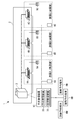
- FIG. 1 is a schematic diagram showing an air conditioning system according to Embodiment 1 of the present invention.
- the air conditioning system 1 of FIG. 1 is installed in a building provided with a plurality of rooms, for example, and includes an air conditioner 2 and a central management device 10.
- the air conditioner 2 is connected to the central management device 10 through a transmission line so that data transmission is possible.
- the central management device 10 transmits and receives various signals to and from the air conditioner 2 through the transmission line. Do.
- a plurality of air conditioners 2 may be connected.
- the air conditioner 2 has an outdoor unit 3 and a plurality of indoor units 4A to 4C connected to the outdoor unit 3 by refrigerant piping.
- the indoor units 4A to 4C are respectively installed in different rooms A to C in the building.
- the room A office room
- the room B conference room 1
- the room C conference room 2
- One indoor unit 4A to 4C is installed for each.
- hand remote controllers 5A to 5C are installed for the user to operate the indoor units 4A to 4C such as set temperature and air volume.
- indoor units 4A to 4C that perform air conditioning in different rooms A to C are installed. It is sufficient that a plurality of indoor units are installed in one room according to the size of the room.
- the central management device 10 includes a reservation management device 20 for managing reservations and use situations of the rooms A to C, and an air conditioning management device 30 for controlling the operation of the air conditioner 2 installed in the rooms A to C. It has.
- the reservation management apparatus 20 is connected to a facility reservation terminal RM for a user to perform a room reservation operation. A user who reserves the rooms A to C reserves the rooms A to C from the facility reservation terminal RM.
- the reservation management apparatus 20 acquires various information input to the facility reservation terminal RM.
- room detection terminals 6A to 6C for detecting entry / exit by the user are installed in the rooms A to C, respectively, and the reservation management device 20 is based on the information detected by the room detection terminals 6A to 6C.
- Perform occupancy management for AC The entrance detection terminals 6A to 6C are installed, for example, at the entrances and exits of the rooms A to C, and are composed of card readers used for unlocking and locking when entering and leaving the room, and are stored in a user information card given to each user in advance.
- the user identification information (ID number in this case) is read, and the user's entry / exit is detected.
- the room entry detection terminals 6A to 6C may be card readers used for unlocking rooms, or human detection sensors and cameras provided in the room entry detection terminals 6A to 6C.
- FIG. 2 is a block diagram showing an example of the air conditioning system of FIG. 1, and the reservation management device 20 and the air conditioning management device 30 of the central management device 10 of FIGS. 1 and 2 will be described.
- the reservation management device 20 includes a reservation management unit 21 and an occupancy management unit 22.
- the reservation management unit 21 manages reservations for the rooms A to C. Specifically, the reservation management unit 21 receives a reservation from the facility reservation terminal RM based on a room information database TB21 that stores information on rooms that can be reserved.
- FIG. 3 is a schematic diagram showing an example of the room information database TB21 of FIG.
- the room identification number in the building, the name of the room, and whether or not the room can be reserved are stored.
- the reservation management unit 21 in FIG. 2 extracts the room identification number (room identification information) and the room name of the room that can be reserved based on the room information database TB21, and the extracted room from the facility reservation terminal RM. Accept reservations.
- the room information database TB21 is set by, for example, an administrator using the setting input device 10A.
- the setting input device 10A includes, for example, a touch panel type input device used in combination with a keyboard, a mouse, and a display screen.
- the reservation management unit 21 in FIG. 2 stores the information input to the facility reservation terminal RM in the reservation storage unit 21a as reservation information.
- the facility reservation terminal RM receives the room identification information of the rooms A to C to be reserved, the usage time of the rooms A to C, information about the user, and the purpose of use of the rooms A to C. These pieces of information are stored as reservation information in the reservation storage unit 21a.
- the user information and the purpose of use of the rooms A to C are stored for each room A to C every hour.
- the occupancy management unit 22 manages the occupancy status of the rooms A to C, and stores the occupancy status of the rooms A to C based on the detection results by the entrance detection terminals 6A to 6C in the storage unit 22a. It is.
- the occupancy management unit 22 acquires the room information scheduled to be used from the reservation management unit 21 when the use start time of the reserved rooms A to C is reached. Then, the occupancy management unit 22 determines that the reservation is canceled if the reserved rooms A to C do not become occupying even after a predetermined period (for example, 20 minutes) from the use start time. To the reservation management unit 21 and the air conditioning management device 30. Then, the reservation management unit 21 deletes the reservation information of the room that has not been in the room from the reservation storage unit 21a.
- the air-conditioning management device 30 controls the air conditioner 2 by setting the energy saving operation mode of the reserved room according to the user information and the purpose of use of the reserved room.
- the air conditioning management device 30 has a function of calculating the priority RP of the reserved room according to the user information and the purpose of use, and setting the energy saving operation mode based on the calculated priority RP.
- the air conditioning management device 30 includes a priority calculation unit 31, an operation mode setting unit 32, and a device control unit 33.
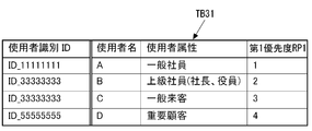
- the priority calculation unit 31 calculates the priority RP of the reserved room according to the user information and the purpose of use. Specifically, the air conditioning management device 30 stores a user information database TB31 that stores user information and the first priority RP1 in association with each other, and a use purpose database that stores the use purpose and the second priority RP2 in association with each other. TB32. Then, the priority calculation unit 31 calculates the priority RP of the reserved room with reference to the user information database TB31 and the usage purpose database TB32 based on the user information and the usage purpose.
- FIG. 4 is an example of the configuration of the user information database TB31 of FIG.
- a user identification ID, a user name, and a user attribute for each user are stored in association with the first priority RP1.
- the attributes of the user are classified into important customers, general visitors, senior employees (president, officer), and general employees, and the first priority RP1 is set higher (larger numerical value) in this order.
- the user attributes in FIG. 4 are examples, and arbitrary attributes can be set according to the use environment, and the numerical value of the first priority RP1 can be set as appropriate.
- the user information is registered by the administrator using the setting input device 10A in advance or at the time of building reception.
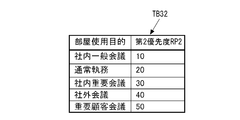
- FIG. 5 is an example of the purpose database TB32 of FIG. As shown in FIG. 5, the usage purpose database TB32 stores the usage purpose of the room such as the in-house general meeting and the normal office work in association with the second priority RP2.
- the priority calculation unit 31 calculates the priority calculation unit 31 based on the first priority RP1 calculated based on the user information and user information database TB31 and the use purpose and use purpose database TB32.
- the priority RP of the reserved room is calculated by adding the second priority RP2.
- the priority calculation unit 31 calculates the priority RP by extracting the highest first priority RP1 among the plurality of users. Note that the priority calculation unit 31 exemplifies the case where the priority RP is calculated based on both the user attribute and the purpose of use of the room, but the priority RP is calculated based on at least the purpose of use of the room. Anything to do.
- the operation mode setting unit 32 sets the energy saving operation mode of each reserved room according to the priority RP calculated by the priority calculation unit 31.
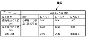
- the air-conditioning management device 30 has an energy saving operation database TB33 that stores the relationship between the priority RP and the energy saving level, and the operation mode setting unit 32 uses the energy saving operation database TB33 to set a reserved room. Set the energy-saving operation mode of the corresponding indoor units 4A to 4C.
- FIG. 6 is a schematic diagram showing an example of the energy saving operation database TB33 of FIG.
- the energy saving operation database TB33 stores a plurality of energy saving operation modes corresponding to the priority RP for each energy saving degree (level).
- This energy saving level is classified into, for example, three levels from level 1 to level 3, with energy saving level 3 having the highest energy saving performance, energy saving level 2 and energy saving level 1 decreasing in order.
- “OFF” means a normal state in which the energy saving mode is not set.
- the setting of the energy saving levels 1 to 3 is performed by the administrator or the like in the setting input device 10A.
- the operation mode setting unit 32 may have a function of setting which energy saving level among the energy saving levels 1 to 3 is used for operation. For example, the operation mode setting unit 32 sets the energy saving level 3 when the number of reserved rooms in the same time period is large, and sets the energy saving level 1 when the number of reserved rooms in the same time period is small. Also good.
- the manager sets the energy saving level from the setting input device 10A.
- FIG. 6 illustrates the case where three energy saving levels are set, the present invention is not limited to this case, and any energy saving level of one or more may be set.
- each energy saving level 1 to 3 the energy saving operation mode is classified for each reserved room based on the priority RP.
- each of the energy saving levels 1 to 3 is classified into three energy saving operation modes of 20% or more of the priority RP, 20 to 30% of the priority RP, and 30% or less of the priority RP.
- the energy saving level 3 is classified into “set temperature 28 ° C.”, “fan”, and “operation stop”, and the energy save level 2 is set to “set temperature 26 ° C.”, “set temperature 26 ° C.”, and “fan”.
- the energy saving level 1 is classified into “set temperature 24 ° C.”, “set temperature 26 ° C.”, and “set temperature 28 ° C.”.
- the operation mode setting unit 32 sets a set temperature and the like for a plurality of rooms A to C reserved in the same time period based on the priority RP calculated by the priority calculation unit 31. Then, the device control unit 33 controls the operations of the air conditioner 2 and the indoor units 4A to 4C according to the energy saving operation mode set in the operation mode setting unit 32.
- the device control unit 33 performs control so as to prohibit the operation by the local remote controllers 5A to 5C installed in the rooms A to C. Thereby, it can prevent that the effect of energy-saving control is impaired by a user's operation.
- control 5A-5C of the room in the time zone where no reservation is made is controlled, or if the air conditioner 2 is operating during the unreserved time zone, the operation of the air conditioner 2 is stopped. Control such as enabling can be set by the administrator.
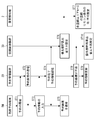
- FIG. 7 is a flowchart illustrating an operation example of the air-conditioning system 1 according to Embodiment 1, and an operation example of the air-conditioning system 1 will be described with reference to FIGS. 1 to 7.
- a vacant room such as a conference room (room A) in a predetermined time zone
- the user inputs a reservation to the facility reservation terminal RM (step ST1).
- the reservation management apparatus 20 of the central management apparatus 10 from the facility reservation terminal RM, the reservation status of each room A to C is changed to the facility reservation terminal RM based on the reservation information stored in the room information database TB21 and the reservation storage unit 21a.
- Step ST2 the reservation management apparatus 20 of the central management apparatus 10 from the facility reservation terminal RM.
- the reservation status of each of the rooms A to C is displayed on the facility reservation terminal RM side, and the user uses the reservation information displayed on the facility reservation terminal RM to obtain the user information, the room to be reserved, and the use of the room.
- the purpose and scheduled use time are input (step ST3).
- the input user information, the room to be reserved, the purpose of use of the room, and the scheduled use time are transmitted from the facility reservation terminal RM to the reservation management apparatus 20.
- the reservation management unit 21 of the reservation management device 20 the reservation information transmitted from the facility reservation terminal RM is analyzed, and the current reservation state stored in the reservation storage unit 21a is referred to.
- the reservation management unit 21 updates the reservation information of the room to be reserved in the reservation storage unit 21a.
- step ST4 the fact that the reservation has been completed is transmitted from the reservation management apparatus 20 to the facility reservation terminal RM (step ST4), and the fact that the reservation has been completed is displayed on the facility reservation terminal RM (step ST5). If the room reservation is duplicated, the fact that the reservation cannot be made is transmitted to the facility reservation terminal RM.
- the priority calculation unit 31 of the air conditioning management device 30 calculates the first priority RP1 based on the room user information and the user information database TB31. Similarly, the second priority RP2 is calculated based on the use purpose of the room and the use purpose database TB32. Then, the first priority RP1 and the second priority RP2 are added, and the priority RP of the reserved room is calculated (step ST6).
- the operation mode setting unit 32 sets the energy saving operation mode for each of the indoor units 4A to 4C installed in the reserved room in the use time zone based on the energy saving operation database TB33, the level setting of the energy saving mode and the priority RP. To do. Then, each of the indoor units 4A to 4C operates based on the energy saving operation mode set in the operation mode setting unit 32 under the control of the device control unit 33 (step ST7).
- step ST8 If the user is not in the room even after a certain period of time after the reservation has been made (step ST8), it is considered that the reservation of the target room has been canceled, and the reservation information in the reservation storage unit 21a Is updated (step ST9), and a reservation for the current time is accepted. If the reservation is changed, for example, the reservation of the room is canceled, the priority RP of the reserved room is recalculated and the control of the air conditioner 2 is reset (step ST10).
- the air conditioner 2 installed in the room where the usage situation changes daily Even if it exists, since the energy saving operation mode of the air conditioner 2 can be set according to the priority RP corresponding to the purpose of use of the room, energy saving control can be performed while maintaining comfort.
- the priority calculation unit 31 has a function of calculating the priority RP of the reserved room from the attribute of the user who uses the reserved room stored in the reservation management apparatus 20 and the user information database TB31, the priority RP It is possible to perform energy-saving control while accurately calculating and maintaining comfort.
- the operation mode setting unit 32 stores a plurality of energy saving operation modes corresponding to the priority RP in the energy saving operation database TB33 for each degree of energy saving (level), and the operation mode setting unit 32 saves energy.
- the energy saving operation mode corresponding to the priority RP of the reserved room is set, the energy saving operation mode considering power consumption such as demand control can be set.
- the embodiment of the present invention is not limited to the above embodiment.
- FIG. 1 the case where the reservation management device 20 and the air conditioning management device 30 are built in the central management device 10 is illustrated, but the reservation management device 20 is installed as a device different from the central management device 10. It may be what was done.
- the user's attributes and purpose of use are transmitted as reservation information from the reservation management device 20 to the central management device 10, and the air conditioning management device 30 performs energy saving control based on the reservation information.
- FIG. 7 illustrates the case where the operation mode is reset when the reservation is canceled.
- the energy saving operation database TB33 is used. The energy saving operation mode may be reset.
- 1 air conditioning system 2 air conditioner, 3 outdoor unit, 4A, 4B, 4C indoor unit, 5A, 5B, 5C local remote control, 6A, 6B, 6C entry detection terminal, 10 central management device, 10A setting input device, 20 Reservation management device, 21 reservation management unit, 21a reservation storage unit, 22 occupancy management unit, 22a storage unit, 30 air conditioning management device, 31 priority calculation unit, 32 operation mode setting unit, 33 device control unit, RM facility reservation terminal , RP priority, RP1 first priority, RP2 second priority, TB21 room information database, TB31 user information database, TB32 purpose database, TB33 energy saving operation database.
Landscapes
- Engineering & Computer Science (AREA)
- Chemical & Material Sciences (AREA)
- Combustion & Propulsion (AREA)
- Mechanical Engineering (AREA)
- General Engineering & Computer Science (AREA)
- Physics & Mathematics (AREA)
- Fuzzy Systems (AREA)
- Mathematical Physics (AREA)
- Signal Processing (AREA)
- Air Conditioning Control Device (AREA)
Abstract
L'invention porte sur une unité de gestion de climatisation qui possède : une section de calcul de priorité pour calculer la priorité d'une pièce réservée sur la base du but prévu des pièces gérées par une unité de gestion de réservation ; une section d'établissement de mode de fonctionnement pour établir, sur la base de la priorité d'une pièce réservée, calculée par la section de calcul de priorité, un mode de fonctionnement en économie d'énergie d'un climatiseur installé dans la pièce ; une section de commande de machine pour commander le climatiseur de telle manière qu'un fonctionnement est effectué dans le mode de fonctionnement en économie d'énergie par la section d'établissement de mode de fonctionnement.
Priority Applications (1)
| Application Number | Priority Date | Filing Date | Title |
|---|---|---|---|
| PCT/JP2014/056784 WO2015136679A1 (fr) | 2014-03-13 | 2014-03-13 | Système de climatisation et dispositif de gestion central |
Applications Claiming Priority (1)
| Application Number | Priority Date | Filing Date | Title |
|---|---|---|---|
| PCT/JP2014/056784 WO2015136679A1 (fr) | 2014-03-13 | 2014-03-13 | Système de climatisation et dispositif de gestion central |
Publications (1)
| Publication Number | Publication Date |
|---|---|
| WO2015136679A1 true WO2015136679A1 (fr) | 2015-09-17 |
Family
ID=54071156
Family Applications (1)
| Application Number | Title | Priority Date | Filing Date |
|---|---|---|---|
| PCT/JP2014/056784 Ceased WO2015136679A1 (fr) | 2014-03-13 | 2014-03-13 | Système de climatisation et dispositif de gestion central |
Country Status (1)
| Country | Link |
|---|---|
| WO (1) | WO2015136679A1 (fr) |
Cited By (5)
| Publication number | Priority date | Publication date | Assignee | Title |
|---|---|---|---|---|
| CN103807988A (zh) * | 2014-03-12 | 2014-05-21 | 侯春海 | 预约舒适性环境温度的空调控制方法 |
| WO2017195371A1 (fr) * | 2016-05-13 | 2017-11-16 | 三菱電機株式会社 | Système de gestion d'installations |
| EP3734175A4 (fr) * | 2017-12-29 | 2021-03-03 | Daikin Industries, Ltd. | Système et procédé de gestion de qualité de l'air |
| WO2022157680A3 (fr) * | 2021-01-21 | 2022-09-01 | Sensorflow Pte Ltd | Procédé |
| CN115046256A (zh) * | 2021-03-08 | 2022-09-13 | 广东美的制冷设备有限公司 | 空调器及其控制方法、控制装置和计算机可读存储介质 |
Citations (9)
| Publication number | Priority date | Publication date | Assignee | Title |
|---|---|---|---|---|
| JPH08505937A (ja) * | 1993-01-22 | 1996-06-25 | ハネウエル・インコーポレーテッド | 温度制御のための制御方法およびシステム |
| JPH08261545A (ja) * | 1995-03-24 | 1996-10-11 | Mitsubishi Electric Corp | 空気調和機 |
| JPH0991354A (ja) * | 1995-09-26 | 1997-04-04 | Matsushita Electric Works Ltd | 部屋の予約管理システム |
| JPH11118228A (ja) * | 1997-10-17 | 1999-04-30 | Mitsubishi Electric Corp | 空気調和システム |
| JP2006349291A (ja) * | 2005-06-17 | 2006-12-28 | Daikin Ind Ltd | 空調制御システムおよび空調制御方法 |
| JP2012107778A (ja) * | 2010-11-15 | 2012-06-07 | Shimizu Corp | 空調制御装置、空調制御方法、空調制御プログラム |
| JP2013013316A (ja) * | 2011-05-30 | 2013-01-17 | Ubiteq Inc | 省エネルギー装置、省エネルギーシステム及び省エネルギープログラム |
| JP2013089208A (ja) * | 2011-10-24 | 2013-05-13 | Mitsubishi Electric Building Techno Service Co Ltd | 空調システム及び空調制御プログラム |
| JP2013221642A (ja) * | 2012-04-13 | 2013-10-28 | Nec Corp | フロア環境最適化システム、最適化装置、最適化方法およびプログラム |
-
2014
- 2014-03-13 WO PCT/JP2014/056784 patent/WO2015136679A1/fr not_active Ceased
Patent Citations (9)
| Publication number | Priority date | Publication date | Assignee | Title |
|---|---|---|---|---|
| JPH08505937A (ja) * | 1993-01-22 | 1996-06-25 | ハネウエル・インコーポレーテッド | 温度制御のための制御方法およびシステム |
| JPH08261545A (ja) * | 1995-03-24 | 1996-10-11 | Mitsubishi Electric Corp | 空気調和機 |
| JPH0991354A (ja) * | 1995-09-26 | 1997-04-04 | Matsushita Electric Works Ltd | 部屋の予約管理システム |
| JPH11118228A (ja) * | 1997-10-17 | 1999-04-30 | Mitsubishi Electric Corp | 空気調和システム |
| JP2006349291A (ja) * | 2005-06-17 | 2006-12-28 | Daikin Ind Ltd | 空調制御システムおよび空調制御方法 |
| JP2012107778A (ja) * | 2010-11-15 | 2012-06-07 | Shimizu Corp | 空調制御装置、空調制御方法、空調制御プログラム |
| JP2013013316A (ja) * | 2011-05-30 | 2013-01-17 | Ubiteq Inc | 省エネルギー装置、省エネルギーシステム及び省エネルギープログラム |
| JP2013089208A (ja) * | 2011-10-24 | 2013-05-13 | Mitsubishi Electric Building Techno Service Co Ltd | 空調システム及び空調制御プログラム |
| JP2013221642A (ja) * | 2012-04-13 | 2013-10-28 | Nec Corp | フロア環境最適化システム、最適化装置、最適化方法およびプログラム |
Cited By (8)
| Publication number | Priority date | Publication date | Assignee | Title |
|---|---|---|---|---|
| CN103807988A (zh) * | 2014-03-12 | 2014-05-21 | 侯春海 | 预约舒适性环境温度的空调控制方法 |
| CN103807988B (zh) * | 2014-03-12 | 2016-09-14 | 侯春海 | 预约舒适性环境温度的空调控制方法 |
| WO2017195371A1 (fr) * | 2016-05-13 | 2017-11-16 | 三菱電機株式会社 | Système de gestion d'installations |
| JPWO2017195371A1 (ja) * | 2016-05-13 | 2018-09-06 | 三菱電機株式会社 | 施設管理システム |
| EP3734175A4 (fr) * | 2017-12-29 | 2021-03-03 | Daikin Industries, Ltd. | Système et procédé de gestion de qualité de l'air |
| WO2022157680A3 (fr) * | 2021-01-21 | 2022-09-01 | Sensorflow Pte Ltd | Procédé |
| CN115046256A (zh) * | 2021-03-08 | 2022-09-13 | 广东美的制冷设备有限公司 | 空调器及其控制方法、控制装置和计算机可读存储介质 |
| CN115046256B (zh) * | 2021-03-08 | 2024-05-28 | 广东美的制冷设备有限公司 | 空调器及其控制方法、控制装置和计算机可读存储介质 |
Similar Documents
| Publication | Publication Date | Title |
|---|---|---|
| CN104782140B (zh) | 空气调和系统以及中央管理装置 | |
| JP5647555B2 (ja) | 施設管理システムおよび方法 | |
| US20120158203A1 (en) | Personal Energy Management System | |
| JP5349369B2 (ja) | 施設管理システム | |
| US9863658B2 (en) | Room management apparatus and method for assigning rooms based on air conditioner state and room temperature | |
| JP2013089208A (ja) | 空調システム及び空調制御プログラム | |
| JP6558921B2 (ja) | 空調制御装置 | |
| WO2015136679A1 (fr) | Système de climatisation et dispositif de gestion central | |
| JP5585261B2 (ja) | 空調制御装置 | |
| EP3841437B1 (fr) | Système et procédé de commande de systèmes de gestion du bâtiment pour des événements planifiés | |
| CN103453619A (zh) | 需求判别装置及判别方法、空调控制系统及控制方法 | |
| WO2014185174A1 (fr) | Contrôleur de gestion d'énergie, système de gestion d'énergie, procédé de gestion d'énergie et programme | |
| JP2017187195A (ja) | 空調制御装置、空調制御システム、空調制御方法、およびプログラム | |
| JP5998598B2 (ja) | フロア環境最適化システム、最適化装置、最適化方法およびプログラム | |
| KR20170130239A (ko) | 객실 관리 시스템 및 그 방법 | |
| JP5924068B2 (ja) | 機器制御システム、機器制御プログラム及び設備制御システム | |
| JP2015183899A (ja) | 空調制御システム | |
| WO2018163272A1 (fr) | Dispositif de climatisation, système de climatisation et procédé de commande | |
| JP2014230402A (ja) | 需要調整システム、需要調整装置、および消費機器管理装置 | |
| CN111578461A (zh) | 运行计划方法、运行控制装置和运行计划系统 | |
| JP5336990B2 (ja) | 施設管理システムおよび方法 | |
| JP5647554B2 (ja) | 施設管理システムおよび方法 | |
| WO2019216943A1 (fr) | Systèmes et procédés de commande basés sur une zone par l'intermédiaire de systèmes d'automatisation de bâtiment hétérogènes | |
| JP2012128641A (ja) | 座席管理システム、座席管理方法及び設備操作システム | |
| JPWO2017013740A1 (ja) | 規則生成装置、規則生成方法、及びプログラム |
Legal Events
| Date | Code | Title | Description |
|---|---|---|---|
| 121 | Ep: the epo has been informed by wipo that ep was designated in this application |
Ref document number: 14885144 Country of ref document: EP Kind code of ref document: A1 |
|
| NENP | Non-entry into the national phase |
Ref country code: DE |
|
| 122 | Ep: pct application non-entry in european phase |
Ref document number: 14885144 Country of ref document: EP Kind code of ref document: A1 |
|
| NENP | Non-entry into the national phase |
Ref country code: JP |