WO2015136791A1 - 情報処理装置、情報処理システムおよび情報処理方法 - Google Patents
情報処理装置、情報処理システムおよび情報処理方法 Download PDFInfo
- Publication number
- WO2015136791A1 WO2015136791A1 PCT/JP2014/081811 JP2014081811W WO2015136791A1 WO 2015136791 A1 WO2015136791 A1 WO 2015136791A1 JP 2014081811 W JP2014081811 W JP 2014081811W WO 2015136791 A1 WO2015136791 A1 WO 2015136791A1
- Authority
- WO
- WIPO (PCT)
- Prior art keywords
- information processing
- information
- image
- processing device
- processing apparatus
- Prior art date
- Legal status (The legal status is an assumption and is not a legal conclusion. Google has not performed a legal analysis and makes no representation as to the accuracy of the status listed.)
- Ceased
Links
Images


Classifications
-
- H—ELECTRICITY
- H04—ELECTRIC COMMUNICATION TECHNIQUE
- H04N—PICTORIAL COMMUNICATION, e.g. TELEVISION
- H04N21/00—Selective content distribution, e.g. interactive television or video on demand [VOD]
- H04N21/40—Client devices specifically adapted for the reception of or interaction with content, e.g. set-top-box [STB]; Operations thereof
- H04N21/43—Processing of content or additional data, e.g. demultiplexing additional data from a digital video stream; Elementary client operations, e.g. monitoring of home network or synchronising decoder's clock; Client middleware
- H04N21/436—Interfacing a local distribution network, e.g. communicating with another STB or one or more peripheral devices inside the home
- H04N21/4363—Adapting the video stream to a specific local network, e.g. a Bluetooth® network
- H04N21/43637—Adapting the video stream to a specific local network, e.g. a Bluetooth® network involving a wireless protocol, e.g. Bluetooth®, RF or wireless LAN [IEEE 802.11]
-
- H—ELECTRICITY
- H04—ELECTRIC COMMUNICATION TECHNIQUE
- H04N—PICTORIAL COMMUNICATION, e.g. TELEVISION
- H04N21/00—Selective content distribution, e.g. interactive television or video on demand [VOD]
- H04N21/40—Client devices specifically adapted for the reception of or interaction with content, e.g. set-top-box [STB]; Operations thereof
- H04N21/43—Processing of content or additional data, e.g. demultiplexing additional data from a digital video stream; Elementary client operations, e.g. monitoring of home network or synchronising decoder's clock; Client middleware
- H04N21/436—Interfacing a local distribution network, e.g. communicating with another STB or one or more peripheral devices inside the home
-
- G—PHYSICS
- G06—COMPUTING OR CALCULATING; COUNTING
- G06F—ELECTRIC DIGITAL DATA PROCESSING
- G06F3/00—Input arrangements for transferring data to be processed into a form capable of being handled by the computer; Output arrangements for transferring data from processing unit to output unit, e.g. interface arrangements
- G06F3/14—Digital output to display device ; Cooperation and interconnection of the display device with other functional units
- G06F3/1423—Digital output to display device ; Cooperation and interconnection of the display device with other functional units controlling a plurality of local displays, e.g. CRT and flat panel display
-
- G—PHYSICS
- G06—COMPUTING OR CALCULATING; COUNTING
- G06F—ELECTRIC DIGITAL DATA PROCESSING
- G06F3/00—Input arrangements for transferring data to be processed into a form capable of being handled by the computer; Output arrangements for transferring data from processing unit to output unit, e.g. interface arrangements
- G06F3/14—Digital output to display device ; Cooperation and interconnection of the display device with other functional units
- G06F3/1454—Digital output to display device ; Cooperation and interconnection of the display device with other functional units involving copying of the display data of a local workstation or window to a remote workstation or window so that an actual copy of the data is displayed simultaneously on two or more displays, e.g. teledisplay
-
- G—PHYSICS
- G09—EDUCATION; CRYPTOGRAPHY; DISPLAY; ADVERTISING; SEALS
- G09G—ARRANGEMENTS OR CIRCUITS FOR CONTROL OF INDICATING DEVICES USING STATIC MEANS TO PRESENT VARIABLE INFORMATION
- G09G5/00—Control arrangements or circuits for visual indicators common to cathode-ray tube indicators and other visual indicators
- G09G5/003—Details of a display terminal, the details relating to the control arrangement of the display terminal and to the interfaces thereto
- G09G5/006—Details of the interface to the display terminal
-
- G—PHYSICS
- G09—EDUCATION; CRYPTOGRAPHY; DISPLAY; ADVERTISING; SEALS
- G09G—ARRANGEMENTS OR CIRCUITS FOR CONTROL OF INDICATING DEVICES USING STATIC MEANS TO PRESENT VARIABLE INFORMATION
- G09G5/00—Control arrangements or circuits for visual indicators common to cathode-ray tube indicators and other visual indicators
- G09G5/14—Display of multiple viewports
-
- H—ELECTRICITY
- H04—ELECTRIC COMMUNICATION TECHNIQUE
- H04N—PICTORIAL COMMUNICATION, e.g. TELEVISION
- H04N21/00—Selective content distribution, e.g. interactive television or video on demand [VOD]
- H04N21/40—Client devices specifically adapted for the reception of or interaction with content, e.g. set-top-box [STB]; Operations thereof
- H04N21/41—Structure of client; Structure of client peripherals
- H04N21/4104—Peripherals receiving signals from specially adapted client devices
- H04N21/4122—Peripherals receiving signals from specially adapted client devices additional display device, e.g. video projector
-
- H—ELECTRICITY
- H04—ELECTRIC COMMUNICATION TECHNIQUE
- H04N—PICTORIAL COMMUNICATION, e.g. TELEVISION
- H04N21/00—Selective content distribution, e.g. interactive television or video on demand [VOD]
- H04N21/40—Client devices specifically adapted for the reception of or interaction with content, e.g. set-top-box [STB]; Operations thereof
- H04N21/43—Processing of content or additional data, e.g. demultiplexing additional data from a digital video stream; Elementary client operations, e.g. monitoring of home network or synchronising decoder's clock; Client middleware
- H04N21/431—Generation of visual interfaces for content selection or interaction; Content or additional data rendering
- H04N21/4312—Generation of visual interfaces for content selection or interaction; Content or additional data rendering involving specific graphical features, e.g. screen layout, special fonts or colors, blinking icons, highlights or animations
- H04N21/4316—Generation of visual interfaces for content selection or interaction; Content or additional data rendering involving specific graphical features, e.g. screen layout, special fonts or colors, blinking icons, highlights or animations for displaying supplemental content in a region of the screen, e.g. an advertisement in a separate window
-
- H—ELECTRICITY
- H04—ELECTRIC COMMUNICATION TECHNIQUE
- H04N—PICTORIAL COMMUNICATION, e.g. TELEVISION
- H04N21/00—Selective content distribution, e.g. interactive television or video on demand [VOD]
- H04N21/40—Client devices specifically adapted for the reception of or interaction with content, e.g. set-top-box [STB]; Operations thereof
- H04N21/43—Processing of content or additional data, e.g. demultiplexing additional data from a digital video stream; Elementary client operations, e.g. monitoring of home network or synchronising decoder's clock; Client middleware
- H04N21/435—Processing of additional data, e.g. decrypting of additional data, reconstructing software from modules extracted from the transport stream
-
- H—ELECTRICITY
- H04—ELECTRIC COMMUNICATION TECHNIQUE
- H04N—PICTORIAL COMMUNICATION, e.g. TELEVISION
- H04N21/00—Selective content distribution, e.g. interactive television or video on demand [VOD]
- H04N21/40—Client devices specifically adapted for the reception of or interaction with content, e.g. set-top-box [STB]; Operations thereof
- H04N21/43—Processing of content or additional data, e.g. demultiplexing additional data from a digital video stream; Elementary client operations, e.g. monitoring of home network or synchronising decoder's clock; Client middleware
- H04N21/438—Interfacing the downstream path of the transmission network originating from a server, e.g. retrieving encoded video stream packets from an IP network
- H04N21/4383—Accessing a communication channel
-
- H—ELECTRICITY
- H04—ELECTRIC COMMUNICATION TECHNIQUE
- H04N—PICTORIAL COMMUNICATION, e.g. TELEVISION
- H04N21/00—Selective content distribution, e.g. interactive television or video on demand [VOD]
- H04N21/60—Network structure or processes for video distribution between server and client or between remote clients; Control signalling between clients, server and network components; Transmission of management data between server and client, e.g. sending from server to client commands for recording incoming content stream; Communication details between server and client
- H04N21/65—Transmission of management data between client and server
- H04N21/658—Transmission by the client directed to the server
- H04N21/6587—Control parameters, e.g. trick play commands, viewpoint selection
-
- G—PHYSICS
- G09—EDUCATION; CRYPTOGRAPHY; DISPLAY; ADVERTISING; SEALS
- G09G—ARRANGEMENTS OR CIRCUITS FOR CONTROL OF INDICATING DEVICES USING STATIC MEANS TO PRESENT VARIABLE INFORMATION
- G09G2330/00—Aspects of power supply; Aspects of display protection and defect management
- G09G2330/02—Details of power systems and of start or stop of display operation
- G09G2330/021—Power management, e.g. power saving
-
- G—PHYSICS
- G09—EDUCATION; CRYPTOGRAPHY; DISPLAY; ADVERTISING; SEALS
- G09G—ARRANGEMENTS OR CIRCUITS FOR CONTROL OF INDICATING DEVICES USING STATIC MEANS TO PRESENT VARIABLE INFORMATION
- G09G2340/00—Aspects of display data processing
- G09G2340/02—Handling of images in compressed format, e.g. JPEG, MPEG
-
- G—PHYSICS
- G09—EDUCATION; CRYPTOGRAPHY; DISPLAY; ADVERTISING; SEALS
- G09G—ARRANGEMENTS OR CIRCUITS FOR CONTROL OF INDICATING DEVICES USING STATIC MEANS TO PRESENT VARIABLE INFORMATION
- G09G2340/00—Aspects of display data processing
- G09G2340/04—Changes in size, position or resolution of an image
-
- G—PHYSICS
- G09—EDUCATION; CRYPTOGRAPHY; DISPLAY; ADVERTISING; SEALS
- G09G—ARRANGEMENTS OR CIRCUITS FOR CONTROL OF INDICATING DEVICES USING STATIC MEANS TO PRESENT VARIABLE INFORMATION
- G09G2340/00—Aspects of display data processing
- G09G2340/12—Overlay of images, i.e. displayed pixel being the result of switching between the corresponding input pixels
-
- G—PHYSICS
- G09—EDUCATION; CRYPTOGRAPHY; DISPLAY; ADVERTISING; SEALS
- G09G—ARRANGEMENTS OR CIRCUITS FOR CONTROL OF INDICATING DEVICES USING STATIC MEANS TO PRESENT VARIABLE INFORMATION
- G09G2350/00—Solving problems of bandwidth in display systems
-
- G—PHYSICS
- G09—EDUCATION; CRYPTOGRAPHY; DISPLAY; ADVERTISING; SEALS
- G09G—ARRANGEMENTS OR CIRCUITS FOR CONTROL OF INDICATING DEVICES USING STATIC MEANS TO PRESENT VARIABLE INFORMATION
- G09G2370/00—Aspects of data communication
- G09G2370/04—Exchange of auxiliary data, i.e. other than image data, between monitor and graphics controller
-
- G—PHYSICS
- G09—EDUCATION; CRYPTOGRAPHY; DISPLAY; ADVERTISING; SEALS
- G09G—ARRANGEMENTS OR CIRCUITS FOR CONTROL OF INDICATING DEVICES USING STATIC MEANS TO PRESENT VARIABLE INFORMATION
- G09G2370/00—Aspects of data communication
- G09G2370/10—Use of a protocol of communication by packets in interfaces along the display data pipeline
-
- G—PHYSICS
- G09—EDUCATION; CRYPTOGRAPHY; DISPLAY; ADVERTISING; SEALS
- G09G—ARRANGEMENTS OR CIRCUITS FOR CONTROL OF INDICATING DEVICES USING STATIC MEANS TO PRESENT VARIABLE INFORMATION
- G09G2370/00—Aspects of data communication
- G09G2370/16—Use of wireless transmission of display information
-
- G—PHYSICS
- G09—EDUCATION; CRYPTOGRAPHY; DISPLAY; ADVERTISING; SEALS
- G09G—ARRANGEMENTS OR CIRCUITS FOR CONTROL OF INDICATING DEVICES USING STATIC MEANS TO PRESENT VARIABLE INFORMATION
- G09G2370/00—Aspects of data communication
- G09G2370/20—Details of the management of multiple sources of image data
-
- H—ELECTRICITY
- H04—ELECTRIC COMMUNICATION TECHNIQUE
- H04W—WIRELESS COMMUNICATION NETWORKS
- H04W84/00—Network topologies
- H04W84/02—Hierarchically pre-organised networks, e.g. paging networks, cellular networks, WLAN [Wireless Local Area Network] or WLL [Wireless Local Loop]
- H04W84/10—Small scale networks; Flat hierarchical networks
- H04W84/12—WLAN [Wireless Local Area Networks]
Definitions
- This technology relates to an information processing apparatus. Specifically, the present invention relates to an information processing apparatus, an information processing system, and an information processing method for exchanging various types of information using wireless communication.
- various types of information can be exchanged between the two information processing apparatuses using wireless communication without being connected by a wired line.
- an image based on image data transmitted from the information processing apparatus on the transmission side can be displayed on the display unit of the information processing apparatus on the reception side.
- the present technology has been created in view of such a situation, and an object thereof is to appropriately display image information among a plurality of information processing apparatuses.
- the present technology has been made to solve the above-mentioned problems.
- the first aspect of the present technology is other information according to Wi-Fi (Wireless Fidelity), CERTIFIED Miracast specifications (technical specification name: Wi-Fi Display).
- the wireless communication unit that performs real-time image transmission with the processing device, and the second image information to be displayed in the non-displayable area included in the first image information transmitted from the other information processing device,
- An information processing apparatus including a control unit that performs control to display a composite image obtained by combining one image information and the second image information on a display unit, an information processing method thereof, and a program that causes a computer to execute the method.
- the second image information to be displayed in the non-displayable area included in the first image information transmitted from the other information processing apparatus is acquired, and a composite image obtained by combining the first image information and the second image information is obtained. This brings about the effect of displaying on the display unit.
- control unit includes the display disabled area and the second image information in the first image information based on command information related to the display disabled area transmitted from the other information processing apparatus. May be specified. This brings about the effect
- control unit identifies the non-displayable area in the first image information based on the position and size of the non-displayable area in the first image information included in the command information. You may do it. Accordingly, there is an effect that the non-displayable area in the first image information is specified based on the position and size of the non-displayable area included in the command information.
- control unit may acquire the second image information from an external device based on address information related to the second image information included in the command information.
- the second image information is obtained from the external device based on the address information related to the second image information included in the command information.
- the control unit when the control unit receives the command information, the control unit transmits confirmation information for accessing the second image information to the external device, and the control unit transmits the confirmation information to the second image information.
- the second image information may be acquired from the external device after receiving permission information permitting access from the external device.
- the control unit when the control unit receives the command information, the control unit transmits confirmation information for the other information processing device to access the second image information to the external device.
- the other information processing device acquires the second image information from the external device after receiving permission information permitting the access of the other information processing device to the second image information from the external device.
- the setting information may be transmitted to the other information processing apparatus.
- control unit acquires the second image information from the external device and transmits the setting information to the other information processing device after transmitting the setting information to the other information processing device. You may make it do. Thereby, after transmitting the setting information to another information processing apparatus, the second image information is acquired from the external apparatus and transferred to the other information processing apparatus.
- control unit may perform display control of the composite image based on control information regarding an image displayed in the non-displayable area included in the command information. This brings about the effect
- control unit causes the operation image to be displayed on the composite image based on operation image information related to the operation image displayed in the non-displayable area included in the command information. It may be. Thereby, based on the operation image information included in the command information, the operation image is displayed so as to be superimposed on the composite image.
- the non-displayable area may be a display area of an image that is copyright-managed in the first image information displayed by the other information processing apparatus. This brings about the effect that the copyright-managed image is acquired and used for the composite image.
- the wireless communication unit performs real-time image transmission with the plurality of other information processing devices, and the control unit is transmitted from the plurality of other information processing devices. You may make it display the said some synthetic image regarding several 1st image information simultaneously on the said display part. Accordingly, there is an effect that a plurality of synthesized images related to a plurality of pieces of first image information transmitted from a plurality of other information processing apparatuses are simultaneously displayed on the display unit.
- the second aspect of the present technology is a wireless communication unit that performs real-time image transmission with another information processing device in accordance with the Wi-Fi CERTIFIED Miracast specification, and image information displayed on the display unit.
- the command information related to the non-displayable area included in the image information to be transmitted to and displayed on the information processing apparatus is transmitted to the other information processing apparatus, and the image information other than the non-displayable area in the image information is transmitted to the other information processing apparatus.
- An information processing device including a control unit that performs control to be transmitted to the device, an information processing method thereof, and a program that causes a computer to execute the method.
- the command information related to the non-displayable area included in the image information displayed on the display unit and transmitted to and displayed on the other information processing apparatus is transmitted to the other information processing apparatus, and the display in the image information is displayed. This brings about the effect of transmitting image information other than the unusable area to another information processing apparatus.
- real-time image transmission is performed with a sink device according to the Wi-Fi CERTIFIED Miracast specification, and image information displayed on the display unit is transmitted to the sink device for display.
- a source device that transmits command information related to the non-displayable area included in the first image information to the sink device, and transmits image information other than the non-displayable region in the first image information to the sink device; and a Wi-Fi CERTIFIED Based on the command information, the second image information to be displayed in the non-displayable area included in the first image information transmitted from the source device is transmitted in real time with the source device according to the Miracast specification. To obtain and combine the first image information and the second image information.
- the source device transmits to the sink device command information related to the non-displayable area included in the first image information displayed on the display unit and transmitted to the sink device and displayed.
- the sink device transmits image information other than the non-displayable area to the sink device, and the sink device acquires the second image information to be displayed in the non-displayable area included in the first image information transmitted from the source device based on the command information.
- the combined image obtained by combining the first image information and the second image information is displayed on the display unit.
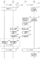
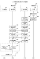
- 3 is a sequence chart illustrating an example of communication processing between devices included in the communication system 100 according to the first embodiment of the present technology.
- 3 is a sequence chart illustrating an example of communication processing between devices included in the communication system 100 according to the first embodiment of the present technology.
- 3 is a sequence chart illustrating an example of communication processing between devices included in the communication system 100 according to the first embodiment of the present technology.
- 3 is a sequence chart illustrating an example of communication processing between devices included in the communication system 100 according to the first embodiment of the present technology.
- 3 is a sequence chart illustrating an example of communication processing between devices included in the communication system 100 according to the first embodiment of the present technology.
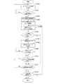
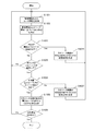
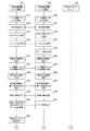
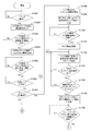
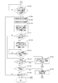
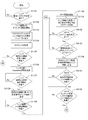
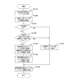
- 7 is a flowchart illustrating an example of a processing procedure of data transmission processing by the information processing device 200 according to the first embodiment of the present technology.
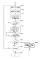
- FIG. 7 is a flowchart illustrating an example of a processing procedure of a data transmission rate control process by the information processing device 300 according to the first embodiment of the present technology.
- 3 is a sequence chart illustrating a communication processing example between a source device and a sink device according to the first embodiment of the present technology.
- 3 is a sequence chart illustrating a communication processing example between a source device and a sink device according to the first embodiment of the present technology.
- 3 is a sequence chart illustrating a communication processing example between a source device and a sink device according to the first embodiment of the present technology. It is a figure which shows the system configuration example of the communication system 700 in 2nd Embodiment of this technique.
- FIG. 12 is a sequence chart illustrating an example of connection processing performed between a source device and a sink device according to the second embodiment of the present technology.
- 12 is a sequence chart illustrating an example of communication processing between devices included in the communication system 700 according to the second embodiment of the present technology.
- 12 is a sequence chart illustrating an example of communication processing between devices included in the communication system 700 according to the second embodiment of the present technology.
- 24 is a flowchart illustrating an example of a processing procedure of a data transmission process performed by the information processing device 710 according to the second embodiment of the present technology.
- 24 is a flowchart illustrating an example of a processing procedure of a data transmission process performed by the information processing device 710 according to the second embodiment of the present technology.
- 22 is a flowchart illustrating an example of a processing procedure of a data reception process performed by the information processing device 730 according to the second embodiment of the present technology.
- 22 is a flowchart illustrating an example of a processing procedure of a data reception process performed by the information processing device 730 according to the second embodiment of the present technology. It is a figure which shows typically an example of the flow of the image data exchanged between each apparatus which comprises the communication system 700 in 2nd Embodiment of this technique. It is a figure showing an example of system configuration of communication system 705 in a 3rd embodiment of this art.
- 22 is a sequence chart illustrating a communication processing example between devices included in the communication system 705 according to the third embodiment of the present technology. 22 is a sequence chart illustrating a communication processing example between devices included in the communication system 705 according to the third embodiment of the present technology. 22 is a sequence chart illustrating a communication processing example between devices included in the communication system 705 according to the third embodiment of the present technology. 22 is a sequence chart illustrating a communication processing example between devices included in the communication system 705 according to the third embodiment of the present technology.
- 22 is a flowchart illustrating an example of a processing procedure of a data transmission process performed by the information processing device 710 according to the third embodiment of the present technology. 22 is a flowchart illustrating an example of a processing procedure of a data transmission process performed by the information processing device 710 according to the third embodiment of the present technology. It is a figure which shows typically an example of the flow of the image data exchanged between each apparatus which comprises the communication system 700 in 4th Embodiment of this technique. It is a sequence chart which shows the example of a communication process between each apparatus which comprises the communication system 700 in 4th Embodiment of this technique.
- 27 is a flowchart illustrating an example of a processing procedure of a data transmission process performed by the information processing device 710 according to the fourth embodiment of the present technology.
- 27 is a flowchart illustrating an example of a processing procedure of a data transmission process performed by the information processing device 710 according to the fourth embodiment of the present technology.
- 27 is a flowchart illustrating an example of a processing procedure of a data reception process performed by the information processing device 730 according to the fourth embodiment of the present technology.
- 27 is a flowchart illustrating an example of a processing procedure of a data reception process performed by the information processing device 730 according to the fourth embodiment of the present technology.
- FIG. 27 is a flowchart illustrating an example of a processing procedure of a data transmission process performed by the information processing device 710 according to the fourth embodiment of the present technology. It is a block diagram which shows an example of a schematic structure of a smart phone. It is a block diagram which shows an example of a schematic structure of a car navigation apparatus.
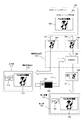
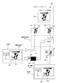
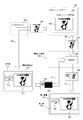
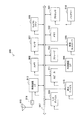
- FIG. 1 is a block diagram illustrating a system configuration example of the communication system 100 according to the first embodiment of the present technology.
- the communication system 100 includes an information processing device 200, an information processing device 300, and an information processing device 400.
- the communication system 100 is a communication system in which the information processing apparatus 300 receives data (for example, image data and audio data) transmitted from at least one of the information processing apparatus 200 and the information processing apparatus 400.
- the information processing apparatuses 200, 300, and 400 are transmission / reception devices having a wireless communication function.
- the information processing devices 200, 300, and 400 are display devices (for example, personal computers) and portable information processing devices (for example, smartphones and tablet terminals) that have a wireless communication function.
- the information processing apparatuses 200, 300, and 400 have IEEE (Institute of Electrical and Electronics Electronics) (802.11), IEEE 802.15, IEEE 802.16, 3GPP (3rd Generation Partnership Project) specifications (for example, W-CDMA (for example).
- Wireless communication based on Wideband Code Division Multiple Access
- GSM Global System for Mobile Communications
- WiMAX Worldwide Interoperability for Microwave Access
- WiMAX2 Long Term Evolution, LTE-A (Advanced) Device.
- the information processing apparatuses 200, 300, and 400 can exchange various types of information using a wireless communication function.
- Wi-Fi Wireless Fidelity
- TDLS Transmission Link Setup
- ad hoc network ad hoc network
- mesh network ad hoc network
- Wi-Fi CERTIFIED Miracast technical specification: Wi-Fi Display
- Wi-Fi CERTIFIED Miracast uses Wi-Fi Direct and TDLS technologies to transmit audio and display images that are played back on one terminal to other terminals, and the other terminals can transmit the audio, This is a mirroring technology that outputs image data.
- Wi-Fi CERTIFIED Miracast realizes UIBC (User Input Back Channel) on TCP / IP (Transmission Control Protocol / Internet Protocol).
- UIBC is a technique for transmitting operation information of an input device such as a mouse or a keyboard from one terminal to the other terminal.
- other remote desktop software for example, VNC (Virtual Network Computing) may be applied.
- H.Fi CERTIFIED Miracast images (videos) are recorded on, for example, H.Fi. H.264 is used for compression / decompression.
- H. H.264 can be adjusted on the transmission side.
- H.264 is not limited thereto. 265 (e.g., HEVC (high-efficiency-video coding), SHVC (scalable-video coding-extensions-of high-efficiency video-coding)), MPEG (Moving-Picture Experts Group) 4, JPEG (Joint-1 Photographic Experts Group) 2000. .
- a line-based codec for example, Wavelet, DCT (Discrete Cosine Transform)
- DCT Discrete Cosine Transform
- a codec that reduces a transmission rate without performing compression such as DCT or Wavelet by obtaining a difference from a previous code amount region of a specific code amount region (such as a picture or a bundle of multiple lines or a macro block).
- the image (video) may be transmitted / received without compression.
- the information processing apparatus 200 illustrates an example in which image data and audio data generated by an imaging operation are transmission targets.
- the information processing apparatus 400 is an example in which content (for example, content including image data and audio data) stored in a storage unit (for example, a hard disk) is a transmission target.
- a storage unit for example, a hard disk
- an electronic device for example, a personal computer, a game machine, a smartphone, or a tablet terminal
- another electronic device including a display unit for example, an imaging device, a game machine, a smartphone, or a tablet terminal
- content stored in an ISP Internet Services Provider
- a wireless or wired network may be a transmission target.
- image data generated by the imaging operation of the information processing apparatus 200 is transmitted to the information processing apparatus 300, and the image 11 based on the image data is displayed on the display unit 351 of the information processing apparatus 300.
- content stored in a storage unit (for example, a hard disk) of the information processing device 400 is transmitted to the information processing device 300, and an image 12 based on the content is displayed on the display unit 351 of the information processing device 300.
- the information processing device (source device) on the source side is the information processing devices 200 and 400
- the information processing device (sink device) on the sink side is the information processing device 300.
- An example is shown.
- the information transmission range 101 is an information transmission range (service range) when the information processing apparatus 300 is used as a reference.
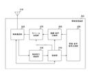
- FIG. 2 is a block diagram illustrating a functional configuration example of the information processing device 200 according to the first embodiment of the present technology. Note that the functional configuration related to wireless communication of the information processing apparatus 400 is substantially the same as that of the information processing apparatus 200. For this reason, in the first embodiment of the present technology, only the information processing apparatus 200 will be described, and the description of the information processing apparatus 400 will be omitted.
- the information processing apparatus 200 includes an antenna 210, a wireless communication unit 220, a control signal receiving unit 230, a control unit 240, an image / audio signal generation unit 250, an image / audio compression unit 260, and a stream transmission unit 270. Is provided.
- the wireless communication unit 220 uses the wireless communication to control each piece of information (for example, image data and audio data) with another information processing device (for example, the information processing device 300) based on the control of the control unit 240.
- Information processing device for example, the information processing device 300
- the wireless communication unit 220 uses the wireless communication to control each piece of information (for example, image data and audio data) with another information processing device (for example, the information processing device 300) based on the control of the control unit 240.
- the wireless communication unit 220 uses the wireless communication to control each piece of information (for example, image data and audio data) with another information processing device (for example, the information processing device 300) based on the control of the control unit 240.
- the image data generated by the image / audio signal generation unit 250 is compressed by the image / audio compression unit 260, and the compressed image data (image stream) is wirelessly transmitted. It is transmitted from the antenna 210 via the communication unit 220.
- the wireless communication unit 220 performs real-time image transmission with another information processing apparatus
- the wireless communication unit 220 can transmit / receive each information to / from another information processing apparatus (for example, the information processing apparatus 300) using a plurality of frequency channels.
- another information processing apparatus for example, the information processing apparatus 300
- the wireless communication unit 220 has a function capable of transmitting and receiving three types of frequency channels of 2.4 GHz, 5 GHz, and 60 GHz is shown.
- the sink device for example, the information processing apparatus 300 controls which frequency channel is used by each source device. Can do.
- the control signal receiving unit 230 includes a control signal (for example, exchange with the information processing device 300) transmitted from another information processing device (for example, the information processing device 300) among the pieces of information received by the wireless communication unit 220. Information). Then, the control signal receiving unit 230 outputs the acquired control signal to the control unit 240.
- the control unit 240 performs control related to each piece of information transmitted from the information processing apparatus 200.
- the control unit 240 controls the image / sound signal generation unit 250 and the image / sound compression unit 260 based on the control signal received by the control signal receiving unit 230.
- the control unit 240 performs control for changing the resolution of the image data to be transmitted and the number of audio channels, and control for changing the image area of the image data to be transmitted. That is, the control unit 240 performs transmission control (for example, data transmission rate control, scalability transmission rate control) of a stream to be transmitted based on the control signal received by the control signal receiving unit 230.
- control unit 240 has a function of measuring a radio wave propagation state (link radio wave propagation state) when data is transmitted / received to / from the sink device using wireless communication, and the measurement result (the radio wave) Propagation measurement information) may be transmitted to the sink device.
- the radio wave propagation measurement information is, for example, information used when determining whether or not the line quality with the sink device is a quality capable of transmitting and receiving image data and audio data.
- the radio wave propagation measurement information is used, for example, when performing stream transmission control (for example, data transmission speed control, scalability transmission rate control).
- the radio wave propagation measurement information will be described in detail with reference to FIG.
- the control unit 240 may count the number of retransmissions of the same packet, and the stream transmission may be controlled according to the count number.
- the data transmission rate mainly means the rate of occupying the communication path, and includes the meaning of communication speed and communication capacity.
- the resolution is defined as an index of image quality composed of elements such as an image data image frame (vertical and horizontal number of pixels) and image data bit rate (compression rate).
- the stream throughput can be used as an image quality index.
- the number of audio channels includes the meaning of audio recording / playback methods such as monaural (1.0 ch) and stereo (2.0 ch).
- the number of audio channels is defined as a sound quality index composed of elements such as the bit rate (compression rate) of audio data and the number of channels. Further, the stream throughput can be used as an index of sound quality.
- control unit 240 performs control for improving a state that cannot be stabilized by data rate control.
- the control unit 240 grasps the system performance information of the sink device by exchanging information with the sink device (for example, the information processing apparatus 300).
- the system performance information is, for example, performance information related to the sink device system.
- the system performance information includes usable frequency channels, resolution, TCP (Transmission Control Protocol), and UDP (User Datagram Protocol).
- the system performance information is information indicating, for example, encryption method support, SD (Standard Definition) / HD (High Definition) support, and low power consumption mode support.
- control unit 240 performs stream transmission control (for example, data transmission rate control, etc.) that further improves the stability of the entire system of the communication system 100 depending on whether the sink device supports the low power consumption mode. (Scalability transmission rate control) method can be selected.
- the control unit 240 puts information on whether or not the information processing apparatus 200 is a mobile device in the exchange of information with the information processing apparatus 300.
- information on whether or not the information processing apparatus 200 is a mobile device can be included in the capability information regarding the information processing apparatus 200.
- the information processing apparatus 300 recognizes that the information processing apparatus 200 is a mobile device, the information processing apparatus 300 determines that it is not necessary to operate the information processing apparatus 200 based on the relationship with another information processing apparatus connected thereto. Can do.
- the information processing apparatus 200 receives a transmission stop command from the information processing apparatus 300.
- control unit 240 When the control unit 240 grasps the transmission stop command, the control unit 240 can power down the functions of the image / audio signal generation unit 250, the image / audio compression unit 260, and the stream transmission unit 270 for a certain period of time. it can. In addition, the control unit 240 can also shift the wireless communication unit 220 to intermittent reception (a mode in which the wireless communication unit 220 periodically wakes up to such an extent that a command can be received from the information processing apparatus 300 and the other is a power-down mode).
- intermittent reception a mode in which the wireless communication unit 220 periodically wakes up to such an extent that a command can be received from the information processing apparatus 300 and the other is a power-down mode.
- the image / sound signal generation unit 250 generates data (image data, sound data) to be output based on the control of the control unit 240, and outputs the generated data to the image / sound compression unit 260.
- the image / sound signal generation unit 250 includes an imaging unit (not shown) and a sound acquisition unit (not shown).
- the imaging unit for example, a lens, an imaging element, and a signal processing circuit
- the sound acquisition unit for example, a microphone
- the data generated in this way becomes a transmission target to another information processing apparatus (for example, the information processing apparatus 300).
- the image / sound compression unit 260 compresses (encodes) the data (image data and sound data) generated by the image / sound signal generation unit 250 based on the control of the control unit 240. Then, the image / audio compression unit 260 outputs the compressed data (image data and audio data) to the stream transmission unit 270.
- the image / sound compression unit 260 may be realized by execution of encoding by software, or may be realized by execution of encoding by hardware.
- the image / sound compression unit 260 is assumed to function as a codec, but can handle uncompressed images or sounds. Furthermore, it is assumed that the image / sound compression unit 260 also functions as a scalable codec.
- the scalable codec means a codec that can be freely adapted according to, for example, the resolution of the information processing apparatus (sink device) on the receiving side, the network environment, and the like.
- the stream transmission unit 270 transmits the data (image data and audio data) compressed by the image / audio compression unit 260 as a stream from the antenna 210 via the wireless communication unit 220 based on the control of the control unit 240. The processing is performed.
- the information processing apparatus 200 can include a display unit, an audio output unit, an operation reception unit, and the like in addition to the above-described units, which are not illustrated in FIG. Further, although an example in which the information processing device 200 generates image data and audio data to be transmitted is shown, the information processing device 200 may acquire image data and audio data to be transmitted from an external device. Good. For example, the information processing apparatus 200 may acquire image data and audio data to be transmitted from a web camera with a microphone. In addition, the information processing apparatus 200 transmits content (for example, content including image data and audio data) stored in a storage device (for example, a hard disk) regardless of whether the information processing apparatus 200 is inside or outside. You may do it.
- a storage device for example, a hard disk
- the content stored in the storage device is a compressed content.
- the compressed content is compressed by the encoding method defined by the standard adopted by the communication system 100, the compressed content is transmitted without being decoded. You may make it do.
- the display unit (not shown) of the information processing apparatus 200 is a display unit that displays an image generated by the image / audio signal generation unit 250, for example.
- a display panel such as an organic EL (Electro Luminescence), a crystal LED (Light Emitting Diode) display (Crystal LED Display), or an LCD (Liquid Crystal Display) can be used as the display unit.
- the audio output unit (not shown) of the information processing apparatus 200 is an audio output unit (for example, a speaker) that outputs the audio generated by the image / audio signal generation unit 250, for example.
- the image can be output from both the transmitting device and the receiving device, but the sound is preferably output from only one of them.
- the operation reception unit (not shown) of the information processing apparatus 200 is an operation reception unit that receives an operation input performed by a user, and is, for example, a keyboard, a mouse, a game pad, a touch panel, a camera, and a microphone.
- the operation receiving unit and the display unit can be integrally configured using a touch panel that allows a user to input an operation by touching or approaching the finger with the display surface.
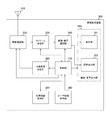
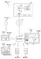
- FIG. 3 is a block diagram illustrating a functional configuration example of the information processing device 300 according to the first embodiment of the present technology.
- the information processing apparatus 300 includes an antenna 310, a wireless communication unit 320, a stream reception unit 330, an image / sound development unit 340, an image / sound output unit 350, a user information acquisition unit 360, a control unit 370, A control signal transmission unit 380 and a management information holding unit 390 are provided.
- the wireless communication unit 320 uses wireless communication to control each piece of information (for example, image data and audio data) with another information processing device (for example, the information processing device 200) based on the control of the control unit 370.
- Information processing device for example, the information processing device 200
- the wireless communication unit 320 uses wireless communication to control each piece of information (for example, image data and audio data) with another information processing device (for example, the information processing device 200) based on the control of the control unit 370.
- image data reception processing image data received by the antenna 310 is expanded (decoded) by the image / sound expansion unit 340 via the wireless communication unit 320 and the stream reception unit 330.
- the developed image data is supplied to the image / sound output unit 350, and an image corresponding to the developed image data is output from the image / sound output unit 350. That is, an image corresponding to the developed image data is displayed on the display unit 351.
- the wireless communication unit 320 performs real-time image transmission with another information processing apparatus according to the Wi-Fi CERTI
- the wireless communication unit 320 can transmit and receive each piece of information with another information processing apparatus (for example, the information processing apparatus 200) using a plurality of frequency channels.
- another information processing apparatus for example, the information processing apparatus 200
- the wireless communication unit 320 has a function capable of transmitting and receiving three types of frequency channels of 2.4 GHz, 5 GHz, and 60 GHz is shown. That is, the wireless communication unit 320 can perform communication using the first frequency band and communication using the second frequency band having a higher data transmission rate than the first frequency band.
- the control unit 370 controls which frequency channel of the plurality of frequency channels is used for wireless communication with each source device.
- the link between the information processing device 200 and the information processing device 300 and the link between the information processing device 400 and the information processing device 300 may be the same frequency channel or different frequency channels. Also good.
- the wireless communication unit 320 has a function capable of transmitting and receiving three types of frequency channels of 2.4 GHz, 5 GHz, and 60 GHz is shown, but the present invention is not limited to this.
- the wireless communication unit 320 may have a function capable of transmitting and receiving other frequency channels and two or more frequency channels.
- the stream receiving unit 330 Based on the control of the control unit 370, the stream receiving unit 330 receives information and a stream (for example, an image stream and an audio stream) of exchange with each source device from among the information received by the wireless communication unit 320. To do. Then, the stream reception unit 330 outputs the received command information to the control unit 370, and outputs the received stream to the image / audio development unit 340 and the control unit 370.
- a stream for example, an image stream and an audio stream
- the information on the exchange with each source device is information transmitted from the source device (for example, the information processing apparatus 200) and includes, for example, an acquisition request for system performance information of the information processing apparatus 300.
- This system performance information is information indicating, for example, usable frequency channels, resolution, TCP, UDP, encryption method support, SD / HD support, and low power consumption mode support.
- the stream receiving unit 330 has a function of measuring a radio wave propagation state (link radio wave propagation state) when data is transmitted / received to / from the sink device using wireless communication. Then, the stream receiving unit 330 outputs the measurement result (radio wave propagation measurement information) to the control unit 370.
- the radio wave propagation measurement information will be described in detail with reference to FIG.
- the image / sound developing unit 340 develops (decodes) a stream (image data and sound data) transmitted from another information processing apparatus (for example, the information processing apparatus 200) based on the control of the control unit 370. is there. Then, the image / sound developing unit 340 outputs the developed data (image data and sound data) to the image / sound output unit 350.
- the image / sound decompression unit 340 may be realized by executing decoding by software, or may be realized by executing decoding by hardware.
- the image / sound development unit 340 is assumed to function as a codec, but can handle an uncompressed image or sound.
- the image / sound development unit 340 also functions as a scalable codec.
- the image / sound output unit 350 includes a display unit 351 and a sound output unit 352.
- the display unit 351 is a display unit that displays each image (for example, the images 11 and 12 shown in FIG. 1) based on the image data developed by the image / sound developing unit 340.
- a display panel such as an organic EL panel, a crystal LED display, or an LCD panel can be used.
- a touch panel on which a user can perform an operation input by touching or approaching his / her finger to the display surface may be used.
- the sound output unit 352 is a sound output unit (for example, a speaker) that outputs various sounds (such as sound related to the image displayed on the display unit 351) based on the sound data developed by the image / sound development unit 340.
- a sound output unit for example, a speaker
- various sounds such as sound related to the image displayed on the display unit 351
- the method can be used.
- a method is used in which the sound volume of the source device assigned to the central channel is set as the main and the sound volume of the source device assigned to the peripheral channel is reduced and played back. Can do. Note that other audio output methods may be used.
- the user information acquisition unit 360 acquires information about the user (user information), and outputs the acquired user information to the control unit 370.
- the user information acquisition unit 360 can acquire user information by receiving input from an operation reception unit (keyboard, mouse, remote controller, game pad, touch panel) that allows the user to directly set the display method.
- the operation accepting unit is an operation member for designating an arbitrary region in the image displayed on the display unit 351, for example.
- the user information acquisition unit 360 receives an input from a device that can grasp the user's intention such as a camera, a microphone, various sensors (for example, a gyro sensor, a sensor that senses a human body), and the like. User information can be acquired.
- the user information acquisition unit 360 is a user when information based on a stream received from another information processing apparatus (for example, the information processing apparatus 200) using wireless communication is output from the image / sound output unit 350.
- User information generated by the operation is acquired.
- This user information is user information generated by a user operation relating to an image displayed on the display unit 351, for example.
- the user information is information generated based on a user operation related to the image displayed on the display unit 351.
- the control unit 370 holds each piece of information acquired by the stream receiving unit 330 in the management information holding unit 390, and manages each source device based on the management information held in the management information holding unit 390. In addition, the control unit 370 performs stream transmission control (for example, data transmission rate control and scalability transmission rate control) so that the stability of the streams transmitted from a plurality of source devices is improved in the entire system.
- stream transmission control for example, data transmission rate control and scalability transmission rate control
- the control unit 370 controls stream transmission (for example, data transmission rate control, scalability transmission) based on the user information acquired by the user information acquisition unit 360 and the management information held in the management information holding unit 390. Rate control). Specifically, the control unit 370 generates a control signal for performing stream transmission control (for example, data transmission rate control, scalability transmission rate control) based on the management information held in the management information holding unit 390. This is generated for each source device, and the generated control signal is output to the control signal transmission unit 380. For example, the control unit 370 changes the resolution of the image displayed on the display unit 351 based on the user information and management information, and generates a control signal for requesting each source device to transmit a transmission rate equivalent to this resolution. To do.
- stream transmission for example, data transmission rate control, scalability transmission
- control unit 370 generates a control signal for changing the image display area in the display unit 351 based on the user information and the management information. For example, the control unit 370 generates a control signal for changing the size of the image on the display unit 351 based on the user information and the management information.
- control unit 370 performs control for setting the frequency channel to be used and the resolution based on the user information and management information. For example, the control unit 370 sets a frequency channel to be used for each source device for a plurality of frequency channels included in the wireless communication unit 320. In addition, when the power consumption mode is different for each frequency channel, the control unit 370 can grasp each mode and set a frequency channel that cares about the power consumption of the mobile device. That is, the control unit 370 separately performs the first power consumption mode related to the first frequency band and the second power consumption mode related to the second frequency band having a higher data transmission rate than the first frequency band. Can be set.
- the control signal transmission unit 380 performs transmission processing for transmitting the control signal output from the control unit 370 to another wireless communication device via the wireless communication unit 320 and the antenna 310.
- the management information holding unit 390 is a table that holds information (management information) for managing each source device connected to the information processing apparatus 300 using wireless communication. The contents held by the management information holding unit 390 will be described in detail with reference to FIG.
- FIG. 4 is a diagram schematically illustrating an example of contents held by the management information holding unit 390 according to the first embodiment of the present technology.
- the management information holding unit 390 is a table that holds information (management information) for managing each source device connected to the information processing apparatus 300 using wireless communication.
- the management information holding unit 390 includes terminal identification information 391, frequency channel 392, radio wave propagation measurement information 393, device information 394, band usage level 395, display mode 396, standby / wakeup 397, A multi-receive diversity correspondence 398 is held in association with each other.
- the terminal identification information 391 stores identification information for identifying a source device connected to the information processing apparatus 300 using wireless communication.
- the frequency channel 392 stores the frequency channel actually used by the source device connected to the information processing apparatus 300 using wireless communication.
- the radio wave propagation measurement information 393 stores radio wave propagation measurement information related to the source device connected to the information processing apparatus 300 using wireless communication.
- the radio wave propagation measurement information is measured by the stream receiving unit 330 for each source device connected to the information processing apparatus 300 using wireless communication.
- radio wave propagation measurement information 393 for example, PER (Packet Error Rate), BER (Bit Error Rate), the number of packet retransmissions, and throughput are stored. Further, as the radio wave propagation measurement information 393, for example, a frame drop, SIR (Signal-to-Interference-Ratio), and RSSI (Received-Signal-Strength-Indicator) are stored. Here, SINR (Signal to (Interference plus Noise Ratio) may be used instead of SIR. Note that the radio wave propagation measurement information 393 illustrated in FIG. 4 is an example, and at least one of these may be stored, and other radio wave propagation measurement information is measured and stored by the stream reception unit 330. You may do it.
- radio wave propagation measurement information measured by the source device may be acquired and stored. Further, the packet delay received by the receiving side may be determined, and information regarding this packet delay may be used as the radio wave propagation measurement information.
- This packet delay is one indicator for radio wave propagation because, for example, when an error occurs, a delay occurs in transmission to the receiving side due to retransmission processing in layer 2. Further, the packet delay is an index indicating whether some link characteristic is deteriorated in a wireless system in which a plurality of devices share a wireless band, for example.
- the device information 394 stores the type (source device attribute) of the source device connected to the information processing apparatus 300 using wireless communication. For example, either a mobile device or a stationary device is stored as the source device type. Note that, as the type of the source device, either a device that is used while the power is inserted or another device may be stored. Further, as the type of the source device, either a battery-driven device or any other device may be stored.
- the bandwidth usage level 395 stores the bandwidth usage level by the source device connected to the information processing apparatus 300 using wireless communication.
- the band usage level for example, resolution or throughput can be used.
- the bandwidth usage level may store the throughput being used.
- a predetermined table is prepared, and a number indicating which range of the table corresponds is stored and managed. You may do it.
- the display form 396 stores a data display form (output form) based on a stream transmitted from a source device connected to the information processing apparatus 300 using wireless communication.
- the display form main image (center channel), sub-image (peripheral channel)
- the output form main audio, sub audio
- the display mode may be such that peripheral channels are not displayed.
- the standby / wakeup 397 stores the mode of the source device connected to the information processing apparatus 300 using wireless communication (standby mode, wakeup mode).
- the standby mode and wake-up mode will be described in detail with reference to FIGS.
- the multi-reception diversity support 398 stores information indicating whether the source device connected to the information processing apparatus 300 using wireless communication is compatible with multi-reception diversity.
- the management information held in the management information holding unit 390 associates identification information (terminal identification information 391) for identifying another information processing apparatus and capability information related to the other information processing apparatus.
- the management information held in the management information holding unit 390 includes, as capability information related to other information processing apparatuses, information related to radio wave propagation measurement related to communication with other information processing apparatuses (radio wave propagation measurement information 393), power consumption Information (standby / wakeup 397).
- the management information held in the management information holding unit 390 includes at least information related to a display form for displaying image information (display form 396) as capability information related to another information processing apparatus.
- the information related to the display form is information indicating that the image information is main-displayed or sub-displayed, for example.
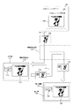
- FIG. 5 is a diagram illustrating a transition example of an image displayed on the display unit 351 of the information processing device 300 according to the first embodiment of the present technology.
- 5A shows an example of a display form in which the image 11 and the image 12 are displayed on the display unit 351 of the information processing apparatus 300 using the image 11 as a central channel and the image 12 as a peripheral channel.
- FIG. 5b shows an example of a display form in which the image 11 and the image 12 are displayed on the display unit 351 of the information processing apparatus 300 using the image 11 as a peripheral channel and the image 12 as a central channel.
- each of the information processing device 200 and the information processing device 400 transmits a standard resolution stream (image data and audio data) to the information processing device 300.
- the image 11 based on the image data from the information processing device 200 and the image 12 based on the image data from the information processing device 400 have the same size.
- the information can be displayed on the display unit 351 of the information processing apparatus 300.
- the given resolution and display area are defined to be the same.
- a scaler function is added to the display unit 351 so that the images 11 and 12 are rescaled and displayed on the display unit 351. May be.
- this function is not used in order to simplify the description.
- each display form of the image 11 and the image 12 for example, the display form set at the previous communication is held, and the images 11 and 12 are displayed in the display unit of the information processing apparatus 300 according to the display form. 351 may be displayed.
- each of the images 11 and 12 may be determined based on the order of connection to the information processing apparatus 300. For example, it is assumed that the information processing apparatus 200 is first connected to the information processing apparatus 300 and the information processing apparatus 400 is connected to the information processing apparatus 300 after this connection. In this case, the image 11 and the image 12 are displayed on the display unit 351 of the information processing apparatus 300 using the image 11 as a central channel and the image 12 as a peripheral channel. That is, based on the connection order to the information processing apparatus 300, the display may be performed in the order of the central channel and the peripheral channel.
- the image 11 is the central channel
- the image 12 is the peripheral channel
- the image 11 and the image 12 are displayed on the display unit 351, the user who uses the image 12 as the central channel.
- information is acquired by the user information acquisition unit 360.
- the viewer performs an operation for setting the image 12 as the central channel using a pointer such as a remote controller or a gesture
- user information regarding the image 12 as the central channel is acquired by the user information acquisition unit 360.
- the image 11 and the image 12 are displayed on the display unit 351 with the image 12 as a central channel and the image 11 as a peripheral channel.
- the display positions of the image 11 and the image 12 on the display surface of the display unit 351 are also determined based on user information (for example, manual operation, line of sight) acquired by the user information acquisition unit 360.
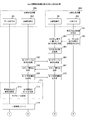
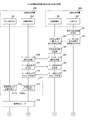
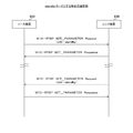
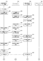
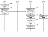
- Example of communication 6 to 8 are sequence charts illustrating communication processing examples between devices included in the communication system 100 according to the first embodiment of the present technology. 6 to 8 illustrate examples of communication processing between the information processing apparatus 200 and the information processing apparatus 300.
- the image / audio signal generation unit 250, the image / audio compression unit 260, and the stream transmission unit 270 are shown as the data transmission system 201 among the units constituting the information processing apparatus 200.
- the antenna 210, the wireless communication unit 220, the control signal receiving unit 230, and the control unit 240 are shown as a line control system 202.
- the antenna 310, the wireless communication unit 320, the stream reception unit 330, the control unit 370, and the control signal transmission unit 380 are shown as the line control system 301 among the units constituting the information processing apparatus 300. Also, the image / sound development unit 340, the image / sound output unit 350, and the user information acquisition unit 360 are shown as the input / output system 302.
- FIGS. 6 to 8 show a connection setup example of the information processing device 200 and the information processing device 300 and a transition example of the power consumption mode in the information processing device 200.
- the control unit 370 of the information processing device 300 causes the management information holding unit 390 (shown in FIG. 4) to hold management information of each source device connected to the information processing device 300 using wireless communication.
- the control unit 370 of the information processing device 300 displays the images 11 corresponding to the two streams transmitted from each of the information processing device 200 and the information processing device 400 based on the previous output form. , 12 are displayed on the display unit 351.
- the information processing apparatus 200 transmits a mode table request (inquiry request for resolution / sound quality, low power consumption mode, etc.) to the information processing apparatus 300 periodically or irregularly (including only at the start) (505, 506).
- This mode table request includes information managed by the information processing device 300 (management information related to the information processing device 300 and information used for communication with the information processing device 200 (for example, displayed by the information processing device 200). Request for possible resolution information, etc.)).
- the information processing apparatus 300 transmits command information corresponding to the mode table request (507, 508).
- This command information is information regarding the information processing apparatus 200 for the information processing apparatus 300 to make a setting request to the information processing apparatus 200 in consideration of the radio wave propagation environment and the display form.
- the command information is information including resolution / sound quality output form information (for example, central channel, peripheral channel), availability of low power consumption mode, manufacturer name, and presence / absence of a multi-reception diversity function.
- the command information includes resolution / sound quality, image / audio codec type, 3D function presence / absence, content protection presence / absence, display device display size, topology information, usable protocols, and setting information for these protocols ( Port information, etc.), connection interface information (connector type, etc.), horizontal synchronization / vertical synchronization position, source device performance priority request information, mode control table response such as availability of low power consumption mode, wireless transmission maximum This is information including throughput or maximum receivable throughput, CPU (Central Processing Unit) power, remaining battery power, and power supply information. Each of these pieces of information is included in a part of capability information.
- the resolution / sound quality output form information regarding the information processing apparatus 200 is, for example, information indicating whether the display form of data from the information processing apparatus 200 is main (central channel) or sub (peripheral channel). It is. Further, the information processing apparatus 300 transmits a request regarding the setting of the resolution / sound quality and the low power consumption mode as a parameter in the command information from the viewpoint of the information processing apparatus 300. Note that the information processing apparatus 300 may transmit, as command information, information related to all source devices in addition to information related to the information processing apparatus 200. In this case, the information processing apparatus 200 selects and uses only information for the own apparatus.
- the control unit 240 of the information processing device 200 specifies whether the data output form from the information processing device 200 is main or sub based on the command information. . In addition, the control unit 240 of the information processing device 200 determines whether the information processing device 300 has a function corresponding to the power consumption operation mode based on the command information. Subsequently, the control unit 240 of the information processing apparatus 200 transmits mode setting information indicating that the specified output form is set to the information processing apparatus 300 (509, 510). Here, it is assumed that the output form of data from the information processing apparatus 200 is specified as sub. Further, it is assumed that the information processing apparatus 300 has a function corresponding to the low power consumption mode. Therefore, the control unit 240 of the information processing device 200 notifies the information processing device 300 of mode setting information for notifying that the specified output form (sub) is set and that the low power consumption mode is set. Transmit (509, 510).
- the low power consumption mode is set by specifying whether the channel is the central channel or the peripheral channel based on the command information, but it is determined whether the channel is the central channel or the peripheral channel.
- the low power consumption mode may be set without using it as a reference.
- the low power consumption mode may be set by exchanging permission flags that can be shifted to the low power consumption mode between the source device and the sink device.
- the control unit 240 of the information processing apparatus 200 sets the image transmission mode (peripheral channel) as the transmission mode (511). Thereby, in the data transmission system 201, the resolution for displaying the peripheral channel and the sound quality for outputting the sub audio are set (512). In the line control system 202, the low power consumption mode is set (513).
- both the sink device and the source device need to have the function.
- mobile devices for example, mobile phones, smartphones, tablet terminals
- the output form of the data from the own apparatus is not main (when it is a sub)
- the setting process (512) only the sound of the source device assigned to the central channel may be reproduced from the speaker and the sound of the source device assigned to the peripheral channel may not be reproduced.
- the sound volume of the source device assigned to the central channel may be set as the main, and the sound volume of the source device assigned to the peripheral channel may be set to be played back at a lower level.
- control unit 370 of the information processing device 300 performs control for setting the low power consumption mode in the information processing device 200 when the output form is set as the peripheral channel (sub display). That is, the control unit 370 of the information processing device 300 performs control to set the power consumption mode in the information processing device 200 based on the output form of the display unit 351 that outputs image information based on the stream.
- the control unit 240 of the information processing apparatus 200 starts intermittent transmission (514 to 522).
- the information processing apparatus 200 stops the transmission process for a fixed time and sleeps each unit (514). Subsequently, when a certain time elapses (514), the information processing apparatus 200 wakes up each unit of the information processing apparatus 200 to perform transmission processing, and performs transmission processing to the information processing apparatus 300 (515 to 520). .
- control unit 240 of the information processing device 200 transmits an inquiry message to the information processing device 300 to confirm whether or not there is any change (for example, a change in output form) in the information processing device 300 (515, 516).
- any change for example, a change in output form
- the control unit 370 of the information processing device 300 transmits a response message for notifying whether there is any change (for example, change of output form) to the information processing device 200 ( 517, 518).
- a response message for notifying whether there is any change for example, change of output form
- the control unit 370 of the information processing device 300 transmits a response message for notifying that there is no change (for example, change in output form) to the information processing device 200 (517, 518).
- the control unit 240 of the information processing device 200 transmits a stream for outputting the peripheral channel and the sub audio to the information processing device 300 (519, 520).
- the information processing apparatus 300 outputs an image and sound based on the received stream (521). For example, as illustrated in b of FIG. 5, the image 11 based on the stream from the information processing apparatus 200 is displayed on the display unit 351 as a peripheral channel.
- the information processing apparatus 200 stops the transmission process for a predetermined time and sleeps each unit (522). Further, intermittent transmission is continuously performed until there is a change request from the information processing apparatus 300.
- the information processing apparatus 300 performs display processing such that an image corresponding to the stream received from the information processing apparatus 200 is interpolated and displayed.
- the information processing apparatus 300 does not have an interpolation processing function.
- the image from the information processing apparatus 200 cannot be displayed on the display unit 351 during the sleep period.
- the transmission of image data from the information processing apparatus 200 may be continuously performed. For example, the last image data when the transmission is stopped among the streams to be transmitted from the information processing apparatus 200 is held in the transmission buffer.
- the image processing of the information processing apparatus 200 is stopped, but the transmission processing is continuously performed for the wireless link, and the transmission of the image data held in the transmission buffer is continuously performed.
- only the image corresponding to the stream transmitted from the information processing apparatus 400 may be displayed on the display unit 351.
- an image corresponding to the stream transmitted from the information processing apparatus 400 can be displayed on the entire surface of the display unit 351.
- the control unit 370 When an output mode setting operation (change operation) is performed by the user (531), as described above, the control unit 370, based on the user information related to the setting operation, the management information holding unit 390 (FIG. The content held in (4) is changed (532, 533).
- the management information holding unit 390 (FIG. The content held in (4) is changed (532, 533).
- a setting operation (change operation) for setting the image 11 based on the image data from the information processing apparatus 200 as a central channel is performed.
- the control unit 370 changes the display form 396 (shown in FIG. 4) of the information processing apparatus 200 in the management information holding unit 390 to “main” (532, 533).
- the control unit 370 of 300 sets a change trigger (534).
- the change trigger is a trigger for notifying the information processing apparatus 200 that the user has performed an output mode setting operation (change operation) when an inquiry message is received from the information processing apparatus 200. With this change trigger, the information processing apparatus 200 is released from the standby mode, and the information processing apparatus 200 is notified that the output mode setting operation (change operation) has been performed by the user.
- each part of the information processing apparatus 200 is woken up and transmission processing to the information processing apparatus 300 is started.
- the control unit 370 of the information processing device 300 transmits a Standby release message to the information processing device 200 (535, 536).
- the control unit 240 of the information processing device 200 Upon receiving the Standby release message (536), the control unit 240 of the information processing device 200 transmits a response message to the information processing device 300 (537, 538).
- the control unit 240 of the information processing apparatus 200 transmits a mode table request to the information processing apparatus 300 (539, 540).
- this mode table request requests transmission of each piece of information managed by the information processing apparatus 300 (management information related to the information processing apparatus 200).
- an exchange for example, a response message to the inquiry message in each process (515 to 518)
- a change for example, a change in output form
- the information processing apparatus 300 transmits command information corresponding to the mode table request (541, 542).
- the information processing apparatus 300 may transmit only the difference information as the command information corresponding to the mode table request (541, 542).
- This difference information is information relating to the change, for example, resolution / sound quality output form information regarding the information processing apparatus 200.
- the control unit 240 of the information processing device 200 specifies whether the data output form from the information processing device 200 is main or sub based on the command information. . Subsequently, the control unit 240 of the information processing apparatus 200 transmits mode setting information indicating that the specified output form is set to the information processing apparatus 300 (543, 544). Here, it is assumed that the data output form from the information processing apparatus 200 is specified to be main. Therefore, the control unit 240 of the information processing device 200 sends mode setting information for notifying that the specified output form (main) is set and that the normal power consumption mode is set. (543, 544).
- each process (539 to 544) may be performed by Capability Re-negotiation.
- Capability Re-negotiation it is not necessary to negotiate again for the setting value in which the output form does not change in the process (534). Examples thereof include wfd-displayedid, wfd-client-rtports, wfd-I2C, and wfd-connectortype.
- the control unit 240 of the information processing device 200 sets the image transmission mode (central channel) as the transmission mode (545).
- the data transmission system 201 sets the resolution for displaying the central channel and the sound quality for outputting the main audio (546).
- a normal power consumption mode is set (547).
- the control unit 240 of the information processing apparatus 200 starts normal transmission processing (548, 549). That is, the information processing apparatus 200 transmits a stream for outputting the central channel and the main audio to the information processing apparatus 300 (548, 549).
- the information processing apparatus 300 outputs an image and sound based on the received stream (550). For example, as illustrated in a of FIG. 5, the image 11 based on the stream from the information processing apparatus 200 is displayed on the display unit 351 as a central channel.
- the display form of the display unit 351 is an example of setting the previous output form (output form when the information processing apparatus 300 is turned off). Indicated.
- another output form may be set.
- the default output form may be always set.
- the output form may be determined based on the order in which the information processing apparatus 300 is connected.
- FIGS. 6 to 8 show an example in which the information processing apparatus 200 inquires about setting information of the information processing apparatus 300 and sets transmission parameters based on the received parameter information.
- the parameter to be set by the information processing apparatus 200 may be requested to the information processing apparatus 300, and the parameter may be set when the information processing apparatus 300 receives a response indicating that there is no problem. An example of this is shown in FIGS.
- Example of communication 9 to 11 are sequence charts illustrating communication processing examples between devices included in the communication system 100 according to the first embodiment of the present technology. 9 and 10 are obtained by modifying a part of the communication processing examples shown in FIGS. For this reason, in FIG. 9 and FIG. 10, parts common to the communication processing examples shown in FIG. 6 to FIG. FIG. 11 is a modification of a part of the communication processing example shown in FIG. For this reason, in FIG. 11, parts common to the communication processing example shown in FIG. 9 are denoted by the same reference numerals, and a part of these descriptions is omitted.
- Each process (561 to 564) shown in FIG. 9 corresponds to each process (501 to 504) shown in FIG.
- the control unit 370 of the information processing device 300 transmits a mode status notification for notifying the output form set by the user to the information processing device 200 (565, 566).
- This mode status notification includes the output form (for example, main or sub) set by the user, the resolution / sound quality that can be set by the information processing apparatus 200, the type of image / audio codec, and the presence / absence of the 3D function.
- Presence / absence of content protection display size of display device, topology information, usable protocols, setting information of these protocols (port information, etc.), connection interface information (connector type, etc.), position of horizontal / vertical synchronization, source To notify device performance priority request information, mode control table response such as compatibility with low power consumption mode, maximum wireless transmission or receivable maximum throughput, CPU power, remaining battery power, power supply information, etc. Information.
- the mode status notification for notifying the output mode related to the setting operation can be transmitted to the information processing apparatus 200. For this reason, the set time (change time) between the information processing apparatus 200 and the information processing apparatus 300 connected by using wireless communication can be shortened.
- the control unit 240 of the information processing device 200 compares the status parameter specified by the received mode status notification with the status parameter of the own device. Subsequently, the control unit 240 of the information processing apparatus 200 determines setting contents (for example, resolution / audio, power consumption mode) based on the comparison result. Subsequently, the control unit 240 of the information processing device 200 transmits a mode setting request for notifying the determined setting contents (for example, resolution / audio, power consumption mode) to the information processing device 300 (567, 568). ).
- the control unit 370 of the information processing device 300 determines whether or not to permit the setting contents (for example, resolution / audio, power consumption mode) specified by the received mode setting request. To do. Then, the control unit 370 of the information processing device 300 transmits a mode setting availability command for notifying the determination result to the information processing device 200 (569, 570).
- the setting contents for example, resolution / audio, power consumption mode
- the control unit 240 of the information processing apparatus 200 confirms the content of the mode setting availability command. For example, when a mode setting permission / prohibition command for permitting the setting content related to the mode setting request transmitted by the information processing apparatus 200 is received, the control unit 240 of the information processing apparatus 200 sets the image transmission mode (peripheral) Channel) is set (571).
- Each process (571 to 574) shown in FIG. 9 corresponds to each process (511 to 514) shown in FIG.
- the processes (575 to 578) shown in FIG. 10 correspond to the processes (519 to 522) shown in FIG.
- the control unit 240 of the information processing device 200 when the mode setting availability command indicating that the setting content related to the mode setting request transmitted by the information processing device 200 is not permitted is received, the control unit 240 of the information processing device 200 newly sets the setting content (for example, resolution / Sound, power consumption mode). Then, the control unit 240 of the information processing device 200 transmits a mode setting request for notifying the newly determined setting contents (for example, resolution / audio, power consumption mode) to the information processing device 300.
- the setting content for example, resolution / Sound, power consumption mode
- Each process (581 to 583) shown in FIG. 10 corresponds to each process (531 to 533) shown in FIG.
- the control unit 370 of the information processing device 300 transmits a mode status change notification for notifying the output form changed by the user to the information processing device 200 (584, 585).
- This mode status change notification indicates the output form (for example, main or sub) changed by the user, the resolution / sound quality that can be set by the information processing apparatus 200, the compatibility with the low power consumption mode, and the like. This is information for notification.
- the control unit 240 of the information processing device 200 determines the setting contents (for example, resolution / voice, power consumption mode).
- the setting content determination process is the same as the determination process described above.
- the control unit 240 of the information processing device 200 transmits a mode change request for notifying the determined setting contents (for example, resolution / voice, power consumption mode) to the information processing device 300 (586, 587). ).
- the control unit 370 of the information processing device 300 determines whether or not to allow the setting contents (for example, resolution / audio, power consumption mode) specified by the received mode change request. To do. Then, the control unit 370 of the information processing device 300 transmits a mode setting availability command for notifying the determination result to the information processing device 200 (588, 589).
- the setting contents for example, resolution / audio, power consumption mode
- the control unit 240 of the information processing apparatus 200 confirms the content of the mode setting availability command and sets the transmission mode (590).
- This confirmation process is the same as the confirmation process described above. Further, the processes (590 to 595) shown in FIG. 10 correspond to the processes (545 to 550) shown in FIG.
- information indicating the switching timing (for example, information for grasping the head of GOP (Group of Picture) or information for grasping the head of the picture) May be transmitted in a stream.
- the source device may transmit information indicating the switching timing to the sink device.
- the sink device that has received the stream can switch the peripheral channel and the center channel at an appropriate timing based on the information indicating the timing.
- FIGS. 6 to 10 show examples of controlling standby / wake-up of the source device connected to the sink device.
- the standby wakeup of the sink device may be controlled based on the standby wakeup of the source device connected to the sink device. For example, when all the source devices connected to the sink device are in the standby state, the sink device can be controlled to be in the standby state. Further, when at least one of the source devices connected to the sink device is waked up, the sink device can be controlled to wake up.
- the sink device notifies the source device that the retained content held in the process (564) has been changed, and transmits a mode table request from the source device.
- FIG. 11 shows a modification of the above.
- the information processing apparatus 300 notifies the information processing apparatus 200 that the output form has been changed (564), and sends a mode status notification to prompt the information processing apparatus 200 to transmit a mode setting request. Transmit (565, 566).
- the information processing apparatus 200 that has received the mode status notification transmits a mode status notification approval indicating that the mode status notification is approved to the information processing apparatus 300 when it is possible to respond (851, 852).
- each processing is performed (853 to 858).
- Each process (853 to 858) corresponds to each process (505 to 510) shown in FIG.
- stream transmission control for example, output mode change (564)
- scalability transmission rate control for example, Data transmission rate control, scalability transmission rate control
- RTSPM5 Message including wfd-triggered-method is currently defined as a command that the information processing apparatus 200 transmits to the information processing apparatus 300.
- the information processing apparatus 200 receives the RTSPM5 Message including wfd-triggered-method, The information processing apparatus 200 can start Capability Re-negotiation with the information processing apparatus 300. That is, management information can be exchanged using RTSPM5 Message including wfd-triggered-method.
- control unit 370 of the information processing apparatus 300 notifies the information processing apparatus 200 of the change in the RTSPM5 Message including wfd-triggered-method defined in the Wi-Fi CERTIFIED Miracast specification when the management information is changed. Control to be transmitted to the information processing apparatus 200 as a command for that purpose. In addition to these commands, new commands may be defined so that they can be equivalent.
- FIG. 12 is a flowchart illustrating an example of a processing procedure of a data transmission process performed by the information processing device 200 according to the first embodiment of the present technology.
- FIG. 12 illustrates an example in which the information processing apparatus 200 first transmits a standard resolution stream (image data and audio data) to the information processing apparatus 300. In this case, it is assumed that the information processing apparatus 300 is outputting based on the stream.
- a standard resolution stream image data and audio data
- control unit 240 transmits a mode table request to the information processing apparatus 300 (step S1001). Subsequently, the control unit 240 determines whether or not the command information is received from the information processing apparatus 300 (step S1002). If the command information is not received, monitoring is continued. If command information cannot be received even after waiting for a certain period of time, the process may be timed out. For example, in Wi-Fi CERTIFIED Miracast, a timeout period of 5 to 9 seconds is set depending on the situation.
- control unit 240 transmits mode setting information indicating that the mode is set based on the received command information to the information processing apparatus 300 (step S1002). S1003).
- control unit 240 sets a mode based on the received command information (step S1004). Further, when a change request for improving the resolution is included in the command information, the control unit 240 sets the resolution of the image and the sound according to the change request. Further, when a change request for reducing the resolution is included in the command information, the control unit 240 sets the resolution of the image and the sound quality of the sound according to the change request.
- control unit 240 performs a transmission process for transmitting the stream to the information processing apparatus 300 according to the setting (step S1005).
- step S1006 determines whether or not the low power consumption mode is set.
- the control unit 240 determines whether or not the low power consumption mode is set.
- the low power consumption mode is not set (that is, the normal power consumption mode is set). In the case), the process proceeds to step S1011.
- the control unit 240 sleeps for a predetermined time (step S1007).
- control unit 240 transmits an inquiry message to the information processing apparatus 300 (step S1008). Subsequently, the control unit 240 determines whether or not a response message has been received from the information processing apparatus 300 (step S1009). If no response message has been received, monitoring is continued. If a response message cannot be received even after waiting for a certain period of time, the process may be terminated by timing out. For example, in Wi-Fi CERTIFIED Miracast, a timeout period of 5 to 9 seconds is set depending on the situation.
- step S1009 When a response message is received from the information processing apparatus 300 (step S1009), the control unit 240 determines whether or not a change request is included in the response message (step S1010). If the response message includes a change request (step S1010), the process returns to step S1001.
- step S1011 determines whether or not the change request has been received. If a change request is received (step S1011), the process returns to step S1001. On the other hand, when the change request has not been received (step S1011), the control unit 240 determines whether a transmission stop operation has been performed (step S1012). If a transmission stop operation is performed (step S1012), the data transmission processing operation is terminated. On the other hand, if the transmission stop operation has not been performed (step S1012), the process returns to step S1005.
- FIG. 13 is a flowchart illustrating an example of a processing procedure of a data transmission rate control process by the information processing device 300 according to the first embodiment of the present technology.
- FIG. 13 illustrates an example in which the information processing apparatus 300 determines setting contents (for example, resolution, power consumption mode) regarding the source device when receiving a stream (image data and audio data).
- setting contents for example, resolution, power consumption mode
- control unit 370 of the information processing device 300 determines the resolution to be used and the frequency channel to be used in accordance with user information for the central channel and the link radio wave propagation environment between the information processing device 300 and each source device. can do.
- the information processing apparatus 300 can grasp the radio wave propagation characteristics by flowing data corresponding to the corresponding throughput through a plurality of frequency channels.
- the information processing apparatus 300 holds a table for grasping ideal throughput for each of a plurality of frequency channels. Then, the information processing apparatus 300 grasps the available data transmission rate of the frequency channel to be used based on the number of source devices used at the same time and the PER, and selects the optimum frequency channel for each frequency channel. It may be.
- control unit 370 acquires management information from the management information holding unit 390, and acquires user information from the user information acquisition unit 360 (step S1021). Subsequently, the control unit 370 determines an output form based on the acquired management information and user information (step S1022). Based on the determined output form, images corresponding to the two streams transmitted from each of the plurality of source devices are displayed on the display unit 351.
- the control unit 370 determines whether or not there is a source device whose PER included in the management information is equal to or less than the threshold (step S1023). If there is a source device whose PER included in the management information is equal to or less than the threshold (step S1023), the control unit 370 determines a change request for improving the resolution of the source device (step S1024). Note that the control unit 370 performs control to allocate a large number of data transmission rates to the central channel according to the output form based on the user information. This change request is included in command information (for example, command information shown in FIG. 6) and transmitted to the source device. Note that it may be determined whether or not the throughput after improving the resolution of the source device is within a threshold, and the stream rate may be controlled based on the determination result.
- Step S1023 When there is no source device whose PER included in the management information is equal to or less than the threshold (step S1023), the control unit 370 determines whether the throughput of each source device is equal to or less than the threshold based on the management information. (Step S1025). That is, it is determined whether there is no problem with the throughput of each link even with the current frequency channel (step S1025).
- step S1025 If the throughput of each source device is not less than or equal to the threshold (step S1025), the process returns to step S1021. On the other hand, if the throughput of each source device is equal to or less than the threshold (step S1025), the control unit 370 determines whether there is a source device corresponding to the low power consumption mode based on the management information (step S1025). Step S1026).
- the control unit 370 determines a change request for setting the low power consumption mode for the source device corresponding to the low power consumption mode. (Step S1028).
- This change request is included in command information (for example, command information shown in FIG. 6) and transmitted to the source device.
- the control unit 370 determines a change request for reducing the resolution of the source device (a source device whose PER is equal to or less than the threshold). (Step S1027).
- This change request is included in command information (for example, command information shown in FIG. 6) and transmitted to the source device.
- step S1029 it is determined whether or not a reception stop operation has been performed. If the reception stop operation has been performed, the operation of the data transmission rate control process is terminated, and the reception stop operation has not been performed. Return to step S1021. Note that when there are source devices that are in the sleep state due to the setting of the low power consumption mode, the number of source devices connected to the information processing apparatus 300 is reduced. In this case, the throughput threshold value in step S1025 may be changed. Further, after changing the throughput threshold in this way, a step corresponding to step S1025 may be further executed.
- the sink device trains the line environment for a certain period of time and notifies the source device of the resolution at which stable video communication can be performed.
- the source device may train the line environment for a certain period of time, request a resolution that enables stable video communication, and use a control protocol to which the sink device responds.
- control unit 370 of the information processing device 300 performs the two transmissions transmitted from each of the source devices based on the management information of the management information holding unit 390 and the user information acquired by the user information acquisition unit 360.
- Stream transmission control for example, data transmission rate control, scalability transmission rate control
- control may be performed so as to minimize the total data transmission rate of the two streams transmitted from the information processing apparatus 200 and the information processing apparatus 400, respectively.
- the maximum allowable value of the total data transmission rate is set in the control unit 370 of the information processing apparatus 300 on the receiving side. Then, after transmitting the change request for reducing the bit rate to the information processing apparatus 200, the control unit 370 transmits the bit rates of the two streams transmitted from the information processing apparatuses 200 and 400 from the stream reception unit 330, respectively. get. Subsequently, the control unit 370 calculates the total data transmission rate of the two acquired streams.
- control unit 370 determines the bit rate of the stream transmitted from the information processing device 400 within a range that does not exceed the set maximum allowable value, and issues a change request for improving the bit rate to the information processing device. 400. Note that if the PER is large and cannot be accommodated in the same frequency channel even when the minimum bit rate is set, another frequency channel may be used. If the image (center channel, peripheral channel) has been stopped for a certain time or longer, the image data may be stopped unless an operation (for example, pointing) from the user occurs.
- Stream control for example, data transmission rate control
- the sink device when the sink device receives and displays a plurality of streams, important images and sounds can be enjoyed with high quality as set by the user from time to time.
- the data transmission rate can be automatically adjusted to the optimum frequency channel, power consumption, and transmission rate.
- management information held in the management information holding unit 390 can be exchanged by using a command prepared in Wi-Fi CERTIFIED Miracast. In this case, it can be performed by capability negotiation or capability re-negotiation defined in the Wi-Fi Display specification.
- capability negotiation or capability re-negotiation include RFC 5939 and Wi-Fi CERTIFIED Miracast specifications.
- capability negotiation or capability re-negotiation is not limited to these, and is defined as exchange of device performance information. Examples of communication using the Wi-Fi CERTIFIED Miracast specification command are shown in FIGS.
- Example of communication using Wi-Fi CERTIFIED Miracast specification command 14 to 16 are sequence charts illustrating an example of communication processing between the source device and the sink device according to the first embodiment of the present technology. 14 to 16 show communication examples using the RTSP protocol. Note that the source device 820 corresponds to the information processing devices 200 and 400, and the sink device 830 corresponds to the information processing device 300.
- an “RTSP M3 Request” (RTSP GET_PARAMETER Request) message transmitted from the source device 820 to the sink device 830 and the sink device 830 in response to this message.
- An “RTSP M3 Response” (RTSP GET_PARAMETER Response) message transmitted to 820 can be used.
- This exchange processing corresponds to, for example, the processing (505 to 508) shown in FIG. 6 and the processing (539 to 542) shown in FIG. On the other hand, it may be appropriately transmitted from the source device 820 to the sink device 830.
- the exchange of the “RTSP M3 Request” (RTSP GET_PARAMETER Request) message and the “RTSP M3 Response” (RTSP GET_PARAMETER Response) message is omitted, and the management information is included in the message transmitted from the source device 820 to the sink device 830. Then, the management information may be transmitted from the source device 820 to the sink device 830, and the sink device 830 may select the information and hold it in the management information holding unit 390. For example, when setting content protection, link protection setup is performed after M3 Response. For this reason, it may be desired that communication can be performed while securing the secrecy of the link once set by performing only the message of M4 or more.
- the exchange of information regarding the power consumption mode can be performed by a predetermined message using the RTSP protocol.
- management information (1) to (3) can be exchanged.
- the “RTSP M12 Request” (“SPSP M12 Request”) transmitted from the source device 820 to the sink device 830 in the above-described (1) “Setting to Standby mode” ( An RTSP SET_PARAMETER (with WFD-standby)) message and an “RTSP M12 Response” (RTSP OK) message transmitted from the sink device 830 to the source device 820 in response thereto can be used.
- SPSP M12 Request (“SPSP M12 Request”) transmitted from the source device 820 to the sink device 830 in the above-described (1) “Setting to Standby mode” ( An RTSP SET_PARAMETER (with WFD-standby)) message and an “RTSP M12 Response” (RTSP OK) message transmitted from the sink device 830 to the source device 820 in response thereto
- RTSP OK “RTSP M12 Response”
- the source device 820 transmits “RTSP M5 Request” ( An RTSP SET_PARAMETER (Request (wfd-trigger-method: PLAY)) message and an “RTSP M5 Response” (RTSP OK) message sent from the sink device 830 to the source device 820 in response to this message are exchanged.
- 830 is an “RTSP M7 Request” (RTSP PLAY Request) message transmitted to the source device 820 and the source device 820 to the sink device 830 in response to this message. Is Shin “RTSP M7 Response” may be used and (RTSP OK) message.
- the terminal identification information is You may make it perform the command to add.
- an example using terminal identification information 391 (DSC200, DR400) shown in FIG. 4 will be described.
- the terminal identification information 391 of the information processing apparatus 200 is set to DSC 200
- the terminal identification information 391 of the information processing apparatus 400 is set to DR400.
- the information processing device 300 (sink device 830) adds the terminal identification information 391 “DSC200” to the “RTSP M7 Request” (RTSP PLAY Request) message transmitted to the information processing device 200 (source device 820).
- RTSP M7 Request (RTSP SET_PARAMETER (Request (wfd-trigger-method: PLAY DSC200)) message.
- the information processing device 300 (sink device 830) is the information processing device 400 (source device 820).
- the terminal identification information 391 “DR400” is added to the “RTSP M7 Request” (RTSP PLAY Request) message sent to the “RTSP M7 Request”.
- st (RTSP SET_PARAMETER (Request (wfd-trigger-method: PLAY DR400)) message.
- the sink device can specify the source device and perform RTSP M7 Request.
- the message regarding “PLAY” has been described as an example, the present invention is not limited to this, and for example, messages such as “SETUP”, “PAUSE”, and “TEARDOWN” can also be used.
- the sink device 830 is transmitted to the source device 820.
- An “RTSP M7 Request” (RTSP PLAY Request) message and an “RTSP M7 Response” (RTSP OK) message transmitted from the source device 820 to the sink device 830 in response to the “RTSP M7 Request” message can be used.
- These exchanges correspond to, for example, the processing (515 to 518) shown in FIG. 7 and the processing (535 to 538) shown in FIG.
- the exchange of the processing (565 to 570) shown in FIG. 9 is performed in response to an “RTSP M12 Request” (RTSP SET_PARAMETER (with WFD-standby)) message transmitted from the sink device 830 to the source device 820. Then, the “RTSP M12 Response” (RTSP OK) message transmitted from the source device 820 to the sink device 830 can be used.
- RTSP M12 Request RTSP SET_PARAMETER (with WFD-standby)
- RTSP OK “RTSP M12 Response”
- the exchange of the processing (584 to 589) shown in FIG. 10 includes an “RTSP M7 Request” (RTSP PLAY Request) message transmitted from the sink device 830 to the source device 820 and the source device 820 in response thereto.
- An “RTSP M7 Response” (RTSP OK) message transmitted from the device to the sink device 830 may be used.
- the wireless communication unit 320 can exchange the capability information by the capability negotiation or the capability re-negotiation defined in the Wi-Fi Display specification.
- capability information is exchanged in RTSP M3 Message in capability negotiation or capability re-negotiation, for example.
- the wireless communication unit 320 of the information processing device 300 performs communication with the source device for exchanging capability information related to the information processing device 300 and capability information related to the information processing device 200.
- the wireless communication unit 220 of the information processing apparatus 200 performs communication with the information processing apparatus 300 for exchanging capability information related to the information processing apparatus 200 and capability information related to the information processing apparatus 300.
- the radio communication units 220 and 320 can exchange capability information by capability negotiation or capability re-negotiation.
- control unit 370 of the information processing device 300 is based on capability information regarding the information processing device 200, radio wave propagation measurement information regarding communication with the information processing device 200, and how the information processing device 300 is used. 200 performs stream transmission control (for example, data transmission rate control, scalability transmission rate control). Although the embodiment of the present technology is different from the stream transmission method, the control unit 240 of the information processing device 200 includes capability information related to the information processing device 200 and radio wave propagation measurement information related to stream communication with the information processing device 300. Based on the control from the information processing apparatus 300 based on the above, stream transmission control with the information processing apparatus 300 (for example, data transmission rate control, scalability transmission rate control) can be performed.
- stream transmission control with the information processing apparatus 300 for example, data transmission rate control, scalability transmission rate control
- control unit 370 of the information processing device 300 performs control to set the power consumption mode in the information processing device 200 based on capability information regarding the information processing device 200 (for example, information indicating whether the device is a mobile device). .
- the control unit 370 may perform control for setting the low power consumption mode in the information processing device 200 based on capability information regarding the information processing device 200 and management information for managing the information processing device 200. it can.
- the control unit 240 of the information processing device 200 sets the power consumption mode based on control from the information processing device 300 based on capability information regarding the information processing device 200.
- an example of a topology with two source devices has been described, but the present technology is not limited to the embodiment of the present technology.
- Second Embodiment> In the second embodiment of the present technology, an example is shown in which group authentication between a source device and a sink device is started using short-range wireless communication, and image transmission is performed by direct connection between the source device and the sink device. Further, in the second embodiment of the present technology, an example in which digital rights management content (DRM (Digital Rights Management) content) is displayed on the source device and the sink device is shown.
- DRM Digital Rights Management
- FIG. 17 is a diagram illustrating a system configuration example of a communication system 700 according to the second embodiment of the present technology.
- the communication system 700 includes a network 701, information processing devices 703, 704, 710, 720, 730, a display device 731, and a DRM content server 740.
- the information processing devices 703, 704, 710, and 720 are information processing devices (source devices) on the transmission side, and the information processing device 730 is an information processing device (sink device) on the reception side.
- the information processing apparatuses 703, 704, 710, and 720 correspond to the information processing apparatus 200 illustrated in FIG. 2
- the information processing apparatus 730 corresponds to the information processing apparatus 300 illustrated in FIG.
- the information processing device 710 is mainly described as the source device, but the same applies to the information processing devices 703, 704, and 720.
- the information processing device 710 is an information processing device (source device) on the transmission side that transmits an image. Further, the information processing device 710 can be connected to the information processing device 730 by P2P direct communication (for example, WiFi Direct). For example, the information processing device 710 is connected to the information processing device 730 using WiFi Direct, and has a protocol that enables image communication such as Wi-Fi CERTIFIED Miracast or DLNA (Digital Living Network Alliance).
- P2P direct communication for example, WiFi Direct
- WiFi Direct for example, the information processing device 710 is connected to the information processing device 730 using WiFi Direct, and has a protocol that enables image communication such as Wi-Fi CERTIFIED Miracast or DLNA (Digital Living Network Alliance).
- the information processing device 730 includes a communication function for connecting to the information processing devices 703, 704, 710, 720, and the DRM content server 740. Further, the information processing device 730 has a function of controlling the entire protocol by connecting to the information processing devices 703, 704, 710, 720, and the DRM content server 740. Further, the information processing device 730 has a communication function for connecting to a local area LAN or a global LAN.
- the information processing device 730 has a display function for displaying an image.
- This display function is a function for displaying a screen of a TV (television) or a projector.
- the information processing device 730 may display an image on a display unit included in the information processing device 730 or may display an image on an external display device. Note that in the second embodiment of the present technology, an example in which a display device 731 separate from the information processing device 730 is provided is shown.
- the information processing device 730 and the display device 731 can be connected by wire or wirelessly.
- a wired cable for example, HDMI (registered trademark) (High-Definition Multimedia Interface), MHL (Mobile High-definition Link), DisplayPort, USB3. 0
- HDMI registered trademark
- MHL Mobile High-definition Link
- DisplayPort USB3. 0
- the wireless LAN can be used for connection.
- a plurality of display devices may be connected to the information processing device 730.
- the DRM content server 740 is a server that stores content (DRM content (digital rights management content)) with certain restrictions on distribution, reproduction, and the like. Further, the DRM content server 740 provides the stored DRM content to each information processing device (information processing devices 703, 704, 710, 720, 730) constituting the communication system 700.
- the DRM content server 740 is realized by, for example, a device including a storage medium (for example, a game machine, a HDD (Hard Disk Drive) recorder, a media server).
- the DRM content server 740 is connected to the information processing device 730 using a wired line or a wireless line.
- a wireless communication for example, a communication method (for example, wireless LAN) provided in the information processing device 730 can be used. Further, infrared rays, other wireless methods, and other communication methods may be used.
- the DRM content server 740 is connected to the information processing devices 703, 704, 710, and 720 via the information processing device 730.
- the DRM content server 740 includes a communication unit 741, a control unit 742, and a DRM content storage unit 743.
- the communication unit 741 transmits and receives information to and from the information processing device 730 via the network 701 based on the control of the control unit 742.
- the control unit 742 controls each unit of the DRM content server 740 based on the control program. For example, the control unit 742 responds to a request from each information processing device (information processing devices 703, 704, 710, 720, and 730) included in the communication system 700, and stores the DRM content stored in the DRM content storage unit 743. To provide control.
- information processing devices 703, 704, 710, 720, and 730 information processing devices 703, 704, 710, 720, and 730
- the DRM content storage unit 743 is a storage unit that stores DRM content.
- the image transmission mode is a communication mode for performing image transmission from the source device to the sink device, and the source device and the sink device are directly connected by P2P.
- the image transmission mode includes an image transmission mode (central channel) for transmitting an image of the central channel and an image transmission mode (peripheral channel) for transmitting an image of the peripheral channel.
- the image transmission mode is a communication mode for transmitting image data for displaying an image on the central channel (central channel region 733) in the display unit of the sink device.
- image data is transmitted through a radio transmission path in a high frequency band.
- the image transmission mode is a communication mode for transmitting image data for displaying an image on the central channel (peripheral channel region 734) in the display unit of the sink device.
- image transmission mode for example, image data is transmitted through a low-frequency band wireless transmission path.
- the communication mode is sequentially switched based on the control of the sink device, such as image transmission mode (peripheral channel) ⁇ image transmission mode (center channel) ⁇ image transmission mode (peripheral channel) ⁇ . Shall.
- FIG. 18 is a diagram schematically illustrating an example of the flow of image data exchanged between devices included in the communication system 700 according to the second embodiment of the present technology.
- FIG. 18 shows an example in which the DRM content 750 stored in the DRM content storage unit 743 of the DRM content server 740 is displayed on the display unit 711 of the information processing device 710 and the display unit 732 of the display device 731.
- the DRM content 750 has certain restrictions on distribution, reproduction, and the like. For this reason, for example, the DRM content 750 displayed on the display unit 711 of the information processing device 710 may not be transferred to the display device 731 and displayed on the display unit 732 by Wi-Fi CERTIFIED Miracast.
- the sink device acquires the DRM content to be displayed in the non-displayable area (DRM content display area) included in the display screen transmitted from the source device from the external device. . Then, the sink device displays a composite image obtained by combining the display screen transmitted from the source device and the DRM content.
- the non-displayable area means an image display area (for example, a display area of DRM content) that is copyright-managed on a display screen displayed by the source device.
- the control unit of the information processing device 710 acquires the DRM content 750 from the DRM content server 740 via the information processing device 730. Then, the control unit of the information processing device 710 causes the display unit 711 to display the acquired DRM content 750. For example, an image based on the DRM content 750 is displayed in the area 712 of the display unit 711, and an image based on the content stored in the information processing device 710 is displayed in the area 713 of the display unit 711.
- the sink device executes only the routing function. In this way, when the sink device performs only the routing function, it is possible to transfer the DRM content.
- the control unit of the information processing device 710 transmits the entire display screen 753 displayed on the display unit 711 to the information processing device 730 by Wi-Fi CERTIFIED Miracast.
- the DRM content 750 has certain restrictions on distribution and reproduction. Therefore, the control unit of the information processing device 710 displays a specific color image (for example, a black image) for the display area of the DRM content 750 (the area 712 of the display unit 711) in the display screen 753 displayed on the display unit 711. 754 is transmitted.
- the display area of the DRM content 750 (the area 712 of the display unit 711) is, for example, an area where the DRM content 750 cannot be displayed by other devices (non-displayable image area).
- the control unit of the information processing device 730 acquires the DRM content 750 from the DRM content server 740. Subsequently, the control unit of the information processing device 730 performs a combining process 756 for combining the acquired DRM content 750 with the display screen 753 transmitted from the information processing device 710. In this composition processing 756, the control unit of the information processing device 730 performs composition processing for compositing an image based on the DRM content 750 in the region of the specific color image 754 in the display screen 753 transmitted from the information processing device 710.
- the control unit of the information processing device 730 transmits the composite image 758 generated by the composition processing 756 to the display device 731 and causes the display unit 732 to display the composite image 758.
- the display unit 732 For example, an image based on the DRM content 750 is displayed in the area 735 of the display unit 732, and an image based on the content stored in the information processing apparatus 710 is displayed in the area 736 of the display unit 732.
- the DRM content 750 stored in the DRM content storage unit 743 of the DRM content server 740 can be displayed on both the display unit 711 of the information processing device 710 and the display unit 732 of the display device 731.
- switching using the source device or switching using the sink device can be a trigger for switching the communication mode of the source device.
- Switching using the source device is active switching by a user operation using the source device, for example.
- the switching using the sink device is switching by a user operation using the sink device, for example.
- the user operation (switching operation) in each device is, for example, a user operation using an operation receiving unit (for example, an operation member or a touch panel) included in each device or a user information acquisition unit (for example, a gesture included in each device). This is a user operation using a detection unit).
- an operation receiving unit for example, an operation member or a touch panel
- a user information acquisition unit for example, a gesture included in each device. This is a user operation using a detection unit).
- Switching using the source device can be, for example, an application input in advance in the source device or an operation input of an operation member as a switching trigger.
- a switching operation is performed in the source device
- a command related to switching of the communication mode is transmitted to the sink device (information processing device 730).
- the sink device performs control to increase / decrease the bandwidth of the source device that transmitted the command while controlling other bandwidths.
- Switching using the sink device can be performed by using, for example, a user operation on the sink device (information processing device 730) as a switching trigger. For example, when a source device switching operation is performed in the sink device (information processing device 730), control is performed to increase or decrease the bandwidth of the source device for which the switching operation is performed while controlling other bandwidths. .
- FIG. 19 is a sequence chart illustrating an example of connection processing performed between the source device and the sink device according to the second embodiment of the present technology.
- FIG. 19 shows an example of connection processing between the information processing device (source device) 710 and the information processing device (sink device) 730.
- the information processing apparatus 710 performs Device Discovery (615).
- the information processing device 710 determines a parent-child relationship and performs authentication processing with the information processing device 730 by forming (620).
- 620 a connection between the information processing device 710 and the information processing device 730 is established.
- the information processing device 710 performs direct communication (Operation) with the information processing device 730 (616).
- GO_Negotiation is performed between the information processing device 710 and the information processing device 730.
- each of the information processing device 710 and the information processing device 730 exchanges the priority for operating as the group owner (GO), and determines that the information processing device with a higher priority operates as the group owner (GO).
- FIG. 19 illustrates an example in which the information processing device 730 has a high priority and the information processing device 730 is determined as the group owner (GO).
- the information processing device 710 transmits GO_Negotiation_Request to the information processing device 730 (621).
- the information processing device 730 transmits GO_Negotiation_Response to the information processing device 710 (622).
- the information processing device 710 transmits GO_Negotiation_Configuration to the information processing device 730 (623).
- the information processing device 730 is determined as the group owner (GO), and the information processing device 710 is determined as the client.
- the information processing device 710 and the information processing device 730 execute WPS (Wi-Fi Protected Access) _exchange (624).
- WPS_exchange the information processing device 710 and the information processing device 730 share credentials (for example, SSID (Service Set Identifier), WPS2 (Wi-Fi Protected Access 2) -PSK (Pre-Shared Key).
- credentials for example, SSID (Service Set Identifier), WPS2 (Wi-Fi Protected Access 2) -PSK (Pre-Shared Key).
- the information processing device 710 and the information processing device 730 execute 4-way_handshake (625).
- the second embodiment of the present technology shows an example in which group authentication between a source device and a sink device is started using short-range wireless communication.
- group authentication can be started using a Wi-Fi Direct over NFC (Near Field Communication) protocol or a Wi-Fi direct using NFC protocol.
- group authentication can be started by causing a source device having an NFC function to directly touch a sink device having an NFC function.
- the Wi-Fi Direct over NFC protocol is a protocol for connecting the source device and the sink device by touching the source device and the sink device.
- this protocol is a protocol that exchanges information for connecting Wi-Fi Direct by touching (or approaching) a source device equipped with an NFC tag to a sink device equipped with an NFC Reader / Writer function. is there.
- group authentication can be started by the user's action of touching the source device directly to the sink device. For this reason, when there is an intention to join the group, the user can actively perform an operation for joining the group.
- the connection to the access point can be switched. Thereby, a more user-friendly interface can be provided. Further, the user can automatically connect to the desired sink device by performing an operation of touching the source device to the desired sink device.
- group authentication may be started by touching the source device to another device instead of directly touching the sink device.
- a reader / writer device is installed near the entrance / exit of a place where image transmission is performed between a source device and a sink device.
- This reader / writer device exchanges various information with an information processing device using near field communication (for example, NFC). Further, the reader / writer device transmits information exchanged with the information processing device to the sink device using a wireless line or a wired line.
- near field communication for example, NFC
- group authentication can be started by touching the reader / writer device with the source device.
- the reader / writer device transmits information on the touched source device (for example, terminal identification information, PIN (Personal Identification Number) code) to the sink device.
- PIN Personal Identification Number
- the PIN code it is preferable to use a unique ID generated uniquely.
- a remote controller for operating a sink device (for example, the information processing device 730) or a display device (for example, the display device 731) may be used instead of the sink device.
- group authentication may be started by touching a source device to a remote controller having an NFC Reader / Writer function.
- the remote control transmits information related to the touched source device (for example, terminal identification information, PIN code) to the sink device.
- Example of communication 20 and 21 are sequence charts illustrating communication processing examples between devices included in the communication system 700 according to the second embodiment of the present technology. 20 and 21 show examples of communication processing between the information processing device (source device) 710, the information processing device (sink device) 730, and the DRM content server 740.
- 20 and 21 show an example in which group authentication is started by causing the information processing device 710 to touch the information processing device 730 directly.
- the information processing device (sink device) 730 functions as a group authentication server. That is, the information processing apparatus (sink device) 730 is provided with a group authentication function.
- the information processing apparatus 710 is provided with an NFC tag function
- the information processing apparatus 730 is provided with an NFC Reader / Write function. Further, the information processing device 730 functions as a DHCP server.
- the information processing device 710 is touched by the information processing device 730 (631, 632).
- the control unit of the information processing device 710 (corresponding to the control unit 240 illustrated in FIG. 2)
- the direct connection is started (633, 634).
- the information processing device 710 becomes a P2P client (635), and the information processing device 730 becomes a P2P GO (group owner) (636). Then, the control unit of the information processing device 710 receives wireless parameters from the information processing device 730 and performs connection processing based on the received wireless parameters.
- control unit of the information processing device 710 acquires an IP address from the information processing device 730 (DHCP server) (637, 638).
- control unit of the information processing device 730 (corresponding to the control unit 370 shown in FIG. 3) performs group authentication processing (639).
- group authentication processing it is determined whether or not the information processing device 710 is allowed to participate in a group operated by an application activated in the information processing device 710 (639). That is, the control unit of the information processing device 730 performs group authentication processing for determining whether or not to permit the information processing device 710 to connect to operate the application started in the information processing device 710 (639).
- the group authentication process whether or not a user operation for permitting the information processing device 710 is performed in any of the source device and the sink device that belong to the same group and are already connected. to decide.
- the information processing device 710 is allowed to participate in the group on the condition that a user operation for permitting the information processing device 710 is performed in any of these devices (source device, sink device). Judgment can be made.
- a display screen for example, hop-up
- a user operation for permitting the information processing device 710 is displayed on at least one display unit of each device (source device, sink device).
- the control unit of the information processing device 730 determines to permit the information processing device 710 to join the group. Perform (639).
- the group authentication process may be performed based on whether or not it is registered in advance. For example, for an information processing apparatus in which terminal identification information is registered in advance in the information processing apparatus 730, the control unit of the information processing apparatus 730 determines to permit participation in the group (639).
- connection permission information is information indicating that the information processing device 710 is permitted to participate in a group operated by an application activated in the information processing device 710.
- connection disapproval information is information indicating that the information processing apparatus 710 is not permitted to participate in a group operated by an application activated in the information processing apparatus 710.
- the control unit of the information processing device 710 transmits capability information related to the information processing device 710 to the information processing device 730 (642, 643).
- This capability information is capability information for performing Wi-Fi CERTIFIED Miracast communication with the information processing device 730.
- the control unit of the information processing device 730 transmits setting request information to the information processing device 710 (644, 645).
- This setting request information is information requesting settings for performing image transmission according to the Wi-Fi CERTIFIED Miracast standard.
- the information processing device 730 performs bandwidth control and display screen control of each source device connected to the information processing device 730. For this reason, it is necessary to request the newly connected information processing apparatus 710 to set parameters that take into account group sharing based on the relationship with other source devices. Therefore, after the information processing device 710 is permitted to join the group, the control unit of the information processing device 730 performs information processing on the information processing device 710 based on each piece of information regarding each source device connected to the information processing device 730.
- the setting request information regarding is transmitted (644, 645).
- the image transmission mode is set in the information processing apparatus 710 as an initial state. Then, the control unit of the information processing device 710 makes a setting request to the information processing device 730 based on the setting request information received from the information processing device 730 (646, 647). Note that when Wi-Fi CERTIFIED Miracast communication is performed between the information processing device 710 and the information processing device 730, the image transmission mode is continuously set in the information processing device 710.
- the control unit of the information processing device 730 transmits confirmation information indicating that reception of an image corresponding to the setting request is permitted to the information processing device 710 (648, 649). ). If reception of an image corresponding to the setting request is not permitted, the control unit of the information processing device 730 transmits confirmation information indicating that to the information processing device 710. In this case, the data transmission processing operation is terminated.
- the control unit of the information processing device 710 When the confirmation information is received (649), the control unit of the information processing device 710 starts a P2P direct connection with the information processing device 730 (650, 651). Then, based on the connection request corresponding to the received confirmation information, the control unit of the information processing device 710 negotiates image parameters and audio parameters with the information processing device 730 and transmits image data (650). , 651).
- the control unit of the information processing device 710 transmits information related to DRM content display to the information processing device 730 (653, 654).
- the information related to DRM content display is, for example, command information related to a display disabled area (DRM content display area) on the display screen, and the display disabled area and the DRM content can be specified.
- the information related to DRM content display is, for example, information related to the DRM content display area and information related to DRM content.
- the information related to the DRM content display area is information for specifying the display size and display position in the display unit 711, for example.
- the information related to the DRM content is, for example, information for specifying the DRM content to be displayed (for example, URL (UniformUniResource Locator)).
- the control unit of the information processing device 730 transmits access confirmation information to the DRM content to the DRM content server 740 (655, 656).
- the DRM content access confirmation information is confirmation information for accessing the DRM content specified by the information related to the DRM content display.
- the control unit 742 of the DRM content server 740 determines whether to permit access to the DRM content. If it is determined that access to the DRM content is permitted, the control unit 742 of the DRM content server 740 transmits access permission information to the DRM content to the information processing device 730 (657, 658). If it is determined that access to the DRM content is not permitted, the control unit 742 of the DRM content server 740 transmits access disapproval information for the DRM content to the information processing device 730. In this case, the information processing device 710 cannot display the DRM content on the display unit 711.
- the control unit of the information processing device 730 transmits an access confirmation end notification to the DRM content to the information processing device 710 (659, 660).
- the DRM content access confirmation end notification is information for notifying that the DRM content server 740 has finished confirming access to the DRM content.
- control unit of the information processing device 730 transmits setting information related to DRM content reception to the information processing device 710 (661, 662).
- the setting information related to DRM content reception is information for the information processing device 710 to receive the DRM content via the information processing device 730 (for example, a bandwidth including resolution, transmission rate, other capability information, and other links). The result of control).
- the control unit of the information processing device 710 acquires the DRM content (663 to 666). In this case, the control unit of the information processing device 710 receives and acquires the DRM content from the DRM content server 740 via the information processing device 730 (663 to 666).
- control unit of the information processing device 710 decodes the received DRM content and causes the display unit 711 to display an image based on the decoded DRM content (667).
- the control unit of the information processing device 710 transmits the entire display screen displayed on the display unit 711 to the information processing device 730 by Wi-Fi CERTIFIED Miracast (668, 669).
- the control unit of the information processing device 710 displays a DRM content display area (display area in the display unit 711) as a specific color image (for example, a black image) in the display screen displayed on the display unit 711. Transmit (668, 669). That is, the entire display screen displayed on the display unit 711 and information related to the DRM content display area are transmitted to the information processing device 730 (668, 669).
- control unit of the information processing device 730 acquires the DRM content to be combined with the entire display screen displayed on the display unit 711 from the DRM content server 740 (670, 671). Then, the control unit of the information processing device 730 performs a combining process for combining the acquired DRM content on the display screen transmitted from the information processing device 710 (672).
- control unit of the information processing device 730 transmits the composite image generated by the composite processing (672) to the display device 731 and causes the display unit 732 to display the composite image (673).
- the control unit of the information processing device 730 causes the DRM content (first display information) to be displayed in the display region (non-displayable region) of the DRM content included in the display screen (first image information) transmitted from the information processing device 710. 2 image information) is acquired. Then, the control unit of the information processing device 730 transmits a composite image obtained by combining the display screen (first image information) and the DRM content (second image information) to the display device 731 and causes the display unit 732 to display the composite image. Take control.
- the control unit of the information processing device 730 based on the command information related to the non-displayable area transmitted from the information processing device 710, displays the non-displayable area on the display screen (first image information) and the DRM content (first 2 image information).
- the control unit of the information processing device 730 can specify the non-displayable area based on the position and size of the non-displayable area included in the command information.
- the control unit of the information processing device 730 receives the DRM content (second image information) from the external device based on address information (for example, URL) regarding the DRM content (second image information) included in the command information. Can be obtained.
- control unit of the information processing device 710 sends command information related to the non-displayable area included in the image information displayed on the display unit 711 and transmitted to the information processing device 730 to be displayed to the information processing device 730. Control to send. Then, the control unit of the information processing device 710 performs control to transmit image information other than the non-displayable area in the image information to the information processing device 730.
- FIG. 22 and 23 are flowcharts illustrating an example of a processing procedure of data transmission processing by the information processing device 710 according to the second embodiment of the present technology. 22 and 23 show an example in which group authentication is started by directly touching the information processing device 710 to the information processing device 730.
- the information processing apparatus 710 has an NFC tag function
- the information processing apparatus 730 has an NFC reader / write function. Further, the information processing device 730 functions as a DHCP server.
- control unit of the information processing device 710 determines whether or not the information processing device 710 has been touched by the information processing device 730 (step S1031). When the information processing device 710 is not touched by the information processing device 730 (step S1031), the monitoring is continued.
- step S1031 When the information processing device 710 is touched by the information processing device 730 (step S1031), the control unit of the information processing device 710 starts a direct connection with the information processing device 730 (step S1032). That is, the information processing device 710 becomes a P2P client, and the information processing device 730 becomes a P2P GO. Then, the control unit of the information processing device 710 receives the wireless parameter from the information processing device 730 and performs a connection process based on the received wireless parameter (step S1033).
- control unit of the information processing device 710 acquires an IP address from the information processing device 730 (DHCP server) (step S1034).
- control unit of the information processing device 710 determines whether connection permission information has been received from the information processing device 730 (step S1035). If connection permission information has not been received from the information processing device 730 (step S1035), the data transmission processing operation ends.
- the control unit of the information processing device 710 transmits the capability information regarding the information processing device 710 to the information processing device 730 (step S1036).
- control unit of the information processing device 710 determines whether or not setting request information has been received from the information processing device 730 (step S1037). If setting request information has not been received (step S1037), monitoring is continued.
- step S1037 When the setting request information is received (step S1037), the image transmission mode is set in the information processing device 710 as an initial state. Then, the control unit of the information processing device 710 makes a setting request to the information processing device 730 based on the setting request information received from the information processing device 730 (step S1038).
- control unit of the information processing device 710 determines whether confirmation information indicating that reception of an image corresponding to the setting request is permitted is received from the information processing device 730 (step S1039). If confirmation information has not been received from the information processing device 730 (step S1039), monitoring is continued.
- the control unit of the information processing device 710 When the confirmation information is received from the information processing device 730 (step S1039), the control unit of the information processing device 710 starts a P2P direct connection with the information processing device 730 (step S1040). Then, the control unit of the information processing device 710 performs image parameter and audio parameter negotiation with the information processing device 730 based on the connection request corresponding to the received confirmation information, and transmits the image data (step). S1041).
- control unit of the information processing device 710 determines whether or not an operation for instructing DRM content display has been performed (step S1042). If the DRM content display instruction operation has not been performed (step S1042), the process returns to step S1041.
- the control unit of the information processing device 710 determines whether to access the DRM content via the information processing device 730 (step S1043). For example, when the information processing device 710 accesses the DRM content via the information processing device 730, a port connected to the local LAN via the information processing device 730 is newly provided, and the DRM connected to the local LAN Access content.
- step S1043 If it is determined that the DRM content is not accessed via the information processing device 730 (step S1043), the DRM content cannot be displayed, and the process returns to step S1041. In this case, since it is determined that the DRM content is not accessed via the information processing device 730, the control unit of the information processing device 710 notifies the user that the DRM content cannot be displayed (a message indicating that display or (Sound output).
- the control unit of the information processing device 710 transmits information related to the DRM content display to the information processing device 730 (step S1044). .
- control unit of the information processing device 710 determines whether an access confirmation end notification to the DRM content has been received (step S1045). If no notification of completion of access confirmation to the DRM content is received, monitoring is continued.
- step S1045 When an access confirmation end notification for DRM content is received (step S1045), the control unit of the information processing device 710 determines whether or not setting information related to DRM content reception has been received (step S1046). If setting information related to DRM content reception has not been received, monitoring is continued.
- step S1046 When the setting information related to DRM content reception is received (step S1046), the control unit of the information processing device 710 receives the DRM content from the DRM content server 740 via the information processing device 730 (step S1047).
- control unit of the information processing device 710 decodes the received DRM content and causes the display unit 711 to display an image based on the decoded DRM content (step S1048).
- the control unit of the information processing device 710 transmits the entire display screen displayed on the display unit 711 to the information processing device 730 by Wi-Fi CERTIFIED Miracast (step S1049).
- the control unit of the information processing device 710 displays a DRM content display area (display area in the display unit 711) as a specific color image (for example, a black image) in the display screen displayed on the display unit 711. Transmit (step S1049).
- step S1050 determines whether or not a change operation for changing the DRM content display position has been performed. If the change operation has not been performed (step S1050), the process proceeds to step S1053.
- step S1050 the control unit of the information processing device 710 transmits a change command related to the DRM content display after the change by the change operation to the information processing device 730 (step S1051).
- This change command is a command for notifying the sink device that the position of the DRM content display area has been changed.
- the change command includes information on the DRM content display area after the change by the change operation (for example, the display size and display position in the display unit 711), and information on the DRM content (URL of the DRM content to be displayed). included.
- the control unit of the information processing device 730 can determine the position of the DRM content from the entire display screen on the display unit 711 of the information processing device 710 based on the change command.
- the control unit of the information processing device 710 determines whether or not change completion information has been received from the information processing device 730 (step S1052).
- This change completion information is information (command) for notifying that the change process corresponding to the change command transmitted from the information processing device 710 has been completed.
- the control unit of the information processing apparatus 710 can change the display position of the DRM content.
- the control unit of the information processing device 710 determines whether or not an operation for ending DRM content display (DRM content display end operation) has been performed (step S1053).
- DRM content display end operation is performed (step S1053)
- the control unit of the information processing device 710 transmits DRM content display end information to the information processing device 730 (step S1054), and the process returns to step S1041.
- This DRM content display end information is information (command) for notifying the sink device that DRM content display is to be ended.
- step S1053 the control unit of the information processing device 710 changes the display area of the DRM content so as not to perform the process of setting the specific color image.
- the control unit of the information processing device 730 ends the DRM content composition processing, decodes the image data transmitted from the information processing device 710 as it is, and displays the display device 731. Can be displayed.
- step S1053 the control unit of the information processing device 710 determines whether or not the line has been disconnected (step S1055). If the line is disconnected (step S1055), the data transmission processing operation ends. If the line is not disconnected (step S1055), the process returns to step S1047.
- FIGS. 24 and 25 are flowcharts illustrating an example of a processing procedure of data reception processing by the information processing device 730 according to the second embodiment of the present technology. 24 and 25 illustrate an example in which group authentication is started when the information processing device 710 is directly touched by the information processing device 730.
- the information processing device 710 is provided with an NFC tag function
- the information processing device 730 is provided with an NFC Reader / Write function. Further, the information processing device 730 functions as a DHCP server.
- control unit of the information processing device 730 determines whether or not the information processing device 730 has been touched by the information processing device 710 (step S1061). When the information processing device 730 is not touched by the information processing device 710 (step S1061), monitoring is continued.
- step S1061 When the information processing device 730 is touched by the information processing device 710 (step S1061), the control unit of the information processing device 730 starts direct connection with the information processing device 710 (step S1062). That is, the information processing device 710 becomes a P2P client, and the information processing device 730 becomes a P2P GO. Then, the control unit of the information processing device 730 transmits a wireless parameter to the information processing device 710 and performs connection processing based on the wireless parameter (step S1063).
- control unit of the information processing device 730 transmits an IP address to the information processing device 710 (step S1064).
- control unit of the information processing device 730 performs group authentication processing (step S1065). If it is determined in this group authentication process that the information processing device 710 is allowed to join the group (step S1066), the control unit of the information processing device 730 transmits connection permission information to the information processing device 710 (step S1066). S1067).
- step S1067 If it is determined that the information processing apparatus 710 is not allowed to join the group in the group authentication process (when authentication is not permitted) (step S1067), the data reception process ends. In this case, the control unit of the information processing device 730 may transmit connection disapproval information to the information processing device 710.
- control unit of the information processing device 730 determines whether or not the capability information related to the information processing device 710 has been received from the information processing device 710 (step S1068).
- Capability information related to the information processing device 710 is received (step S1068), the control unit of the information processing device 730 transmits setting request information to the information processing device 710 (step S1069).
- control unit of the information processing device 730 determines whether a setting request has been received from the information processing device 710 (step S1070). If no setting request has been received, monitoring is continued.
- the control unit of the information processing device 730 transmits confirmation information indicating that reception of an image corresponding to the connection request is permitted to the information processing device 710 (step S1071). ).
- step S1072 the control unit of the information processing device 730 starts P2P direct connection with the information processing device 710 (step S1072).
- the control unit of the information processing device 730 negotiates image parameters and audio parameters with the information processing device 710, and performs image data reception processing (step S1073).
- step S1073 is an example of a first procedure described in the claims.
- control unit of the information processing device 730 determines whether information related to DRM content display has been received from the information processing device 710 (step S1074). If no information related to DRM content display has been received (step S1074), the process returns to step S1073.
- control unit of the information processing device 730 transmits access confirmation information to the DRM content to the DRM content server 740 (step S1075).
- control unit of the information processing device 730 determines whether or not access permission information for DRM content has been received from the DRM content server 740 (step S1076). If the access permission information for the DRM content has not been received (step S1076), the monitoring is continued.
- the control unit of the information processing device 730 transmits an access confirmation end notification to the DRM content to the information processing device 710 (step S1077).
- control unit of the information processing device 730 transmits setting information related to DRM content reception to the information processing device 710 (step S1078). Subsequently, the control unit of the information processing device 730 transmits the DRM content received from the DRM content server 740 to the information processing device 710 (step S1079).
- control unit of the information processing device 730 determines whether or not the entire display screen displayed on the display unit 711 of the information processing device 710 and information regarding the DRM content display area have been received from the information processing device 710. (Step S1080). If the entire display screen and information regarding the DRM content display area have not been received (step S1080), monitoring is continued.
- the control unit of the information processing device 730 acquires the DRM content from the DRM content server 740 (step S1081). Then, the control unit of the information processing device 730 performs a combining process for combining the acquired DRM content on the display screen transmitted from the information processing device 710 (step S1082).
- control unit of the information processing device 730 transmits the combined image generated by the combining process to the display device 731 and causes the display unit 732 to display the combined image (step S1083).
- steps S1080 to S1083 are an example of a second procedure described in the claims.
- control unit of the information processing device 730 determines whether or not a change command has been received from the information processing device 710 (step S1084). If a change command has not been received (step S1084), the process returns to step S1079.
- step S1084 the control unit of the information processing device 730 transmits change completion information corresponding to the received change command to the information processing device 710 (step S1085).
- the control unit of the information processing device 730 determines whether or not DRM content display end information has been received from the information processing device 710 (step S1086).
- the process returns to step S1070.
- the control unit of the information processing device 730 ends the DRM content composition processing, and decodes and displays the image data transmitted from the information processing device 710 as it is. It can be displayed on the device 731.
- step S1086 the control unit of the information processing device 730 determines whether the line has been disconnected (step S1087). If the line is disconnected (step S1087), the data transmission processing operation is terminated. If the line is not disconnected (step S1087), the process returns to step S1079.
- the second embodiment of the present technology an example in which image information transmitted from one source device is displayed on one sink device side is shown.
- the second embodiment of the present technology can also be applied to a case where image information transmitted from a plurality of source devices is simultaneously displayed on one sink device side.
- the display control shown in the first embodiment of the present technology can be applied. That is, the control unit of the information processing device 730 can perform control to transmit a plurality of composite images related to a plurality of display screens transmitted from a plurality of source devices to the display device 731 and display them simultaneously on the display unit 732.
- command information for specifying control information such as PLAY, STOP, fast forward, and rewind performed on the non-displayable image area may be transmitted from the source device to the sink device periodically or irregularly.
- a command that manages from which of the plurality of source devices the PLAY command is received on the sink device side (for example, the command “RTSP M7 Request” (RTSP SET_PARAMETER (Request) received from the information processing device 710) (Wfd-trigger-method: PLAY 710))) is received, in which case the sink device receives the PLAY command destination (for example, the URL of the DRM content server).
- the DRM content for the information processing apparatus 710 can be PLAYed, and functions other than PLAY (for example, STOP, fast forward, rewind, etc.) can also be realized.
- the source device may notify the sink device regularly or irregularly of the picture number, the Decode time from when the source device receives the DRM content until it is displayed, and the like. That is, the control unit of the information processing device 730 can perform display control of the composite image based on the control information regarding the image displayed in the non-displayable area included in the command information.
- the image data to be transmitted may be switched based on the size of the display area of the DRM content in the display unit of the source device (or the display device connected to the source device). For example, when the size of the display area of the DRM content is large with reference to the threshold value, the image data is transmitted from the sink device to the source device with the area corresponding to the DRM content as a black image. On the other hand, when the size of the display area of the DRM content is small with reference to the threshold, the image data of the DRM content is transmitted from the sink device to the source device. That is, the sink device transfers all of the DRM content received by the sink device to the source device or transfers a part of the DRM content received by the sink device to the source device based on the size of the display area of the DRM content. Can be controlled.
- Example when an operation image is displayed on an image based on DRM content In the above, the example in which the sink device displays the combined image in which the DRM content is combined on the display screen displayed on the source device is shown.
- the operation image used for the user operation is displayed on the display screen displayed on the source device.
- This operation image is an image (for example, an icon or a cursor) that moves on the display screen in response to a user operation using an operation member (for example, a keyboard, a mouse, or a touch panel).
- the operation image may be referred to as, for example, an operation sign, pointing information, operation information, or the like.
- the operation image moves on the image based on the DRM content. Even in this case, it is important to display the operation image displayed on the source device on the sink device. Therefore, in the following, an example is shown in which the operation image displayed on the source device is appropriately displayed on the sink device.
- FIG. 26 is a diagram schematically illustrating an example of the flow of image data exchanged between devices included in the communication system 700 according to the second embodiment of the present technology. Since the example shown in FIG. 26 is a modification of FIG. 18, the same reference numerals are given to the portions common to FIG. 18 and the description thereof is omitted.
- FIG. 26 shows an example in which an operation image 760 is displayed so as to overlap an image (image based on the DRM content 750) displayed in the area 712 of the display unit 711.
- the control unit of the information processing device 710 transmits the entire display screen 762 displayed on the display unit 711 to the information processing device 730 by Wi-Fi CERTIFIED Miracast.
- the control unit of the information processing device 710 transmits the area 764 of the operation image 760 in the display area (area 712) of the DRM content 750 on the display screen 762 without using the specific color image 763.
- control unit of the information processing device 730 performs a combining process 765 for combining the DRM content 750 acquired from the DRM content server 740 with the display screen 762 transmitted from the information processing device 710.
- this composition process 765 the control unit of the information processing device 730 performs composition processing for compositing an image based on the DRM content 750 in the region of the specific color image 763 in the display screen 762 transmitted from the information processing device 710.
- the control unit of the information processing device 730 performs a combining process of combining the region 764 of the operation image 760 in the region of the specific color image 763 with an image based on the DRM content 750.
- the control unit of the information processing device 730 transmits the combined image 767 generated by the combining process 765 to the display device 731 and causes the display unit 732 to display it.
- the display unit 732 For example, an image based on the DRM content 750 is displayed in the area 735 of the display unit 732, and the operation image 769 is displayed over the image based on the DRM content 750.
- FIG. 26 shows an example in which the operation image area is transmitted without being a specific color image.
- information for specifying the region of the operation image on the display screen and the display mode (for example, position, shape, and color) of the operation image may be transmitted from the source device to the sink device.
- the sink device can display an operation image based on the operation image information. That is, the control unit of the information processing device 730 can display the operation image on the composite image based on the operation image information regarding the operation image displayed in the non-displayable area included in the command information.
- the third embodiment of the present technology shows an example in which group authentication between a source device and a sink device is started by connecting the source device to an access point.
- DRM content is displayed by connection between a source device and a sink device via an access point and direct connection between the source device and the sink device is shown.
- FIG. 27 is a diagram illustrating a system configuration example of the communication system 705 according to the third embodiment of the present technology.
- the communication system 705 includes a network 701, an access point 702, information processing devices 703, 704, 710, 720, 730, a display device 731, and a DRM content server 740.
- the communication system 705 is a modification of the communication system 700 illustrated in FIG. 17, and therefore, portions common to the communication system 700 are denoted by the same reference numerals, and a part of the description thereof is omitted.
- the access point 702 is a wireless LAN (for example, Wi-Fi) access point (Access Point).
- the access point 702 has an infrastructure mode function of the IEEE 802.11 standard.
- the access point 702 is connected to one or a plurality of information processing devices (for example, a transmission-side information processing device (source device) and a reception-side information processing device (sink device)).
- the access point 702 can be connected to the information processing apparatus 730 via a wired line (for example, Ethernet (registered trademark)).
- a wired line for example, Ethernet (registered trademark)
- the access point 702 can be connected to the information processing device 730 via the network 701.
- the access point 702 may be connected to the internal bus of the information processing device 730 to perform processing.
- the internal bus of the information processing device 730 is, for example, USB (Universal Serial Bus), PCI (Peripheral Components Interconnect), or PCI Express.
- the connection between the access point 702 and the information processing device 730 may be a wireless connection (for example, a wireless LAN) instead of a wired connection.
- the network 701 is connected to the information processing device 730, and the information processing device 730 needs to determine whether it is a transmission / reception process with the access point 702 or a transmission / reception process with the information processing device 710.
- the access point 702 and the information processing devices 703, 704, 710, and 720 correspond to a wireless LAN (for example, IEEE 802.11a / b / g / n / ac / ad).
- a wireless LAN for example, IEEE 802.11a / b / g / n / ac / ad.
- An example of connection using a wireless LAN is shown in which the access point 702 and the information processing device 730 are connected via an Ethernet line.
- the information processing device 710 is an information processing device that can be connected to the access point 702 in the infrastructure mode.
- connection example in which the information processing apparatus 710 connects to the access point 702 in the infrastructure mode will be described.
- the information processing device 710 transmits a connection request signal to the access point 702.
- the information processing apparatus 710 starts an operation (connection establishment operation) for establishing a connection with the access point 702 by transmitting a connection request signal.
- connection establishment operation is an operation for connecting the layer 2 levels. For example, in addition to password authentication based on PID (Packet Identification) performed in a wireless LAN, connection authentication processing for determining whether to connect the information processing device 710 as an application is also required.
- PID Packet Identification
- the information processing device 710 may be connected to the access point 702 and may be a standby device that only exchanges various types of information with the information processing device 730 via the access point 702. Note that when the information processing apparatus 710 is used only as a standby apparatus, the information processing apparatus 710 may not have a protocol that enables image communication.
- the information processing device 710 has a concurrent function (a time division concurrent function or a simultaneous use concurrent function) for connecting to both the access point 702 and the information processing device 730.
- a concurrent function a time division concurrent function or a simultaneous use concurrent function
- the time division concurrent function is realized by accessing two frequencies in a time division manner with one type of physical layer.
- the information processing device 710 includes two types of physical layers, different types of information processing devices can be accessed simultaneously by the two types of physical layers. Thereby, a simultaneous use concurrent function is realized.
- the information processing device 710 when the information processing device 710 has a concurrent function, the information processing device 710 performs time-division or simultaneous transmission to both the access point and the sink device without switching the access point and the sink device. Connection is possible
- the information processing device 730 has a communication function for connecting to the access point 702, the information processing devices 703, 704, 710, 720, and the DRM content server 740.
- the information processing device 730 is connected to the access point 702, the information processing devices 703, 704, 710, 720, and the DRM content server 740, and has a function of controlling the entire protocol. Further, the information processing device 730 has a communication function for connecting to a local area LAN or a global LAN.
- a frequency different from the radio frequency used by the access point 702 for connection between the information processing device 730 and the information processing devices 703, 704, 710, and 720.
- a frequency band such as 2.4 GHz band, 5 GHz band, 60 GHz, or the like such as IEEE802.11a / b / g / n / ac / ad is used is shown.
- IEEE802.11a / b / g / n / ac / ad is used.
- other wireless standards and frequency bands may be used.
- the DRM content server 740 may be provided with a protocol for connecting to the access point 702 and connected to the information processing device 730 via the access point 702.
- the communication mode between the source device and the sink device will be described.
- the communication mode of the standby mode and the image transmission mode is selected in the source device. Shall be set.
- the standby mode is a communication mode in which the connection state via the access point is maintained between the source device and the sink device without performing image transmission from the source device to the sink device. That is, the standby mode is a mode that is set when the sink device is recognized as a network participant.
- image transmission from the source device to the sink device can be performed, but in the standby mode, image transmission from the source device to the sink device cannot be performed. However, it is possible to perform transmission from the source device to the sink device for simple messaging in the standby mode.
- each source such as standby mode ⁇ image transmission mode (peripheral channel) ⁇ image transmission mode (central channel) ⁇ standby mode... It is assumed that the communication mode in the device is sequentially switched.
- (B1) and (B2) can be used as a trigger for switching the communication mode of the source device.
- (B1) Switching using the source device (for example, active switching by a user operation using the source device)
- (B2) Switching using a sink device (for example, switching by a user operation using a sink device)
- the user operation (switching operation) in each device is, for example, a user operation using an operation receiving unit (for example, an operation member or a touch panel) included in each device or a user information acquisition unit (for example, a gesture included in each device). This is a user operation using a detection unit).
- an operation receiving unit for example, an operation member or a touch panel
- a user information acquisition unit for example, a gesture included in each device. This is a user operation using a detection unit).
- (B1) can use, for example, an application input in advance in the source device or an operation input of an operation member as a switching trigger. For example, when a switching operation is performed in the source device, a command related to switching of the communication mode is transmitted to the sink device (information processing device 730). When this command is received, the sink device (information processing device 730) performs control to increase / decrease the bandwidth of the source device that transmitted the command while controlling other bandwidths.
- (B2) can use a user operation in the sink device (information processing device 730) as a switching trigger, for example. For example, when a source device switching operation is performed in the sink device (information processing device 730), control is performed to increase or decrease the bandwidth of the source device for which the switching operation is performed while controlling other bandwidths. .
- FIG. 28 is a diagram illustrating a switching example of the communication mode between the source device and the sink device that are the basis of the present technology.
- a connection method in which the source device 610 and the sink device 612 are indirectly connected via the access point 611 is employed.
- a connection method in which the source device 610 and the sink device 612 are directly connected without using the access point 611 is adopted.
- connection in the standby mode (613) is switched to the connection in the image transmission mode (614). That is, a case is assumed where the standby mode (613) connected via the access point 611 is switched to the image transmission mode (614) connected without going through the access point 611.
- Wi-Fi Direct control P2P Device Discovery, P2P Service Discovery, GO Negotiation
- 4 Way handshake Handshake for wireless LAN security authentication
- IP Internet Protocol
- DHCP Dynamic Host Configuration Protocol
- RTSP Real Time Streaming Protocol
- the access point 611 and the source device 610, and the source device 610 and the sink device 612 are within the same group authentication. In this case, security authentication is performed between the access point 611 and the source device 610. For this reason, it is assumed that there is no security problem even if the setting value between the access point 611 and the source device 610 is used for the connection processing between the source device 610 and the sink device 612.
- an example in which security authentication between the source device and the sink device is omitted and more seamless connection switching is performed is shown.
- processing such as HDCP (High-bandwidth Digital Protection system) IP acquisition and RTP (Real-time Transport Protocol) port setting can be used.
- HDCP High-bandwidth Digital Protection system
- RTP Real-time Transport Protocol
- the source device and the sink device support the TDLS (Tunneled Direct Link Setup) function
- the TDLS protocol may be used.
- FIG. 29 is a diagram schematically illustrating an example of a flow of image data exchanged between devices included in the communication system 705 according to the third embodiment of the present technology. Since the example shown in FIG. 29 is a modification of FIG. 18, the same reference numerals are given to portions common to FIG. 18, and description thereof is omitted.
- FIG. 29 shows an example in which the information processing apparatus 710 acquires the DRM content 750 from the DRM content server 740 via the access point 702.
- the control unit of the information processing device 710 acquires the DRM content 750 from the DRM content server 740 via the access point 702. Then, the control unit of the information processing device 710 causes the display unit 711 to display the acquired DRM content 750.
- the present invention can be similarly applied to the case where the operation image 760 is displayed so as to overlap the image displayed in the area 712 of the display unit 711 (an image based on the DRM content 750).
- Example of communication 30 to 32 are sequence charts illustrating an example of communication processing between devices included in the communication system 705 according to the third embodiment of the present technology.
- 30 to 32 show communication processing examples among the information processing device (source device) 710, the access point 702, the information processing device (sink device) 730, and the DRM content server 740.
- the information processing apparatus (sink device) 730 functions as a group authentication server. That is, the information processing apparatus (sink device) 730 is provided with a group authentication function.
- an application for communicating with the information processing device 730 in the information processing device 710 (an application preinstalled in the information processing device 710) is started (401).
- the application is activated by, for example, a user operation (for example, an application button pressing operation).
- FIGS. 30 to 32 show an example in which each process is started after the source device is directly connected to the access point by default. That is, the information processing device 710 activates an application installed in advance and makes a connection request to the sink device (information processing device 730) via a specific access point (access point 702).
- the information processing apparatus 710 After connecting to the access point 702, the information processing apparatus 710 performs device discovery (corresponding to Device Discovery (615) shown in FIG. 19) and displays a connectable sink device on the display unit 711.
- Device Discovery corresponding to Device Discovery (615) shown in FIG. 19
- a WiFi Direct protocol can be executed via the access point 702
- a message such as ProbeRequest is received
- a device discovery method can be used.
- a device service type can be used by exchanging Device Service Type represented by UPnP (Universal Plug and Play) between Stations connected to the access point 702.
- UPnP Universal Plug and Play
- a selection screen for selecting a desired sink device from a plurality of discovered sink devices can be displayed on the display unit of the source device, and can be selected by a user operation on this selection screen.
- a device closest to the source device may be automatically selected and connected. Note that when automatically selecting the closest device, for example, position information acquired by each device can be used.
- an application is started in the information processing apparatus 710 and a sink device is selected (401).
- 30 to 32 show an example when the information processing device 730 is selected.
- the control unit of the information processing device 710 (corresponding to the control unit 240 shown in FIG. A connection request to the device 730) is made (402 to 405).
- This connection request includes, for example, identification information (for example, terminal identification information 391 shown in FIG. 4) for specifying the information processing device 710 and identification information (application information) for specifying an application to be started. It is.
- the control unit (corresponding to the control unit 370 shown in FIG. 3) of the information processing device 730 performs group authentication processing (406).
- group authentication processing it is determined whether or not the information processing apparatus 710 is to participate in a group that is operated by an application activated in the information processing apparatus 710 (406). That is, the control unit of the information processing device 730 performs group authentication processing for determining whether or not to allow the information processing device 710 to connect to operate the application started in the information processing device 710 (406).
- the group authentication process whether or not a user operation for permitting the information processing device 710 is performed in any of the source device and the sink device that belong to the same group and are already connected. to decide.
- the information processing device 710 is allowed to participate in the group on the condition that a user operation for permitting the information processing device 710 is performed in any of these devices (source device, sink device). Judgment can be made.
- a display screen for example, hop-up
- a user operation for permitting the information processing device 710 is displayed on at least one display unit of each device (source device, sink device).
- the control unit of the information processing device 730 determines to permit the information processing device 710 to join the group. Perform (406).
- group authentication processing may be performed based on whether or not it is registered in the sink device.
- the control unit of the information processing apparatus 730 determines to permit participation in the group (406).
- the control unit of the information processing device 730 makes a determination to permit participation in the group only when it is within a preset time (406).
- the control unit of the information processing device 730 passes the connection permission information to the information processing device 710 via the access point 702. (407 to 410).
- the connection permission information is information indicating that the information processing device 710 is permitted to participate in a group operated by an application activated in the information processing device 710.
- connection rejection information is information indicating that the information processing apparatus 710 is not permitted to participate in a group operated by an application activated in the information processing apparatus 710.
- the control unit of the information processing device 710 transmits the capability information regarding the information processing device 710 to the information processing device 730 via the access point 702. (411 to 414).
- This capability information is capability information for performing Wi-Fi CERTIFIED Miracast communication with the information processing device 730.
- the capability information includes information for performing P2P direct connection to the information processing device 730.
- This setting request information is information requesting settings for performing image transmission according to the Wi-Fi CERTIFIED Miracast standard.
- the information processing device 730 performs bandwidth control and display screen control of each source device connected to the information processing device 730. For this reason, it is necessary to request the newly connected information processing apparatus 710 to set parameters that take into account group sharing based on the relationship with other source devices. Therefore, after the information processing device 710 is permitted to join the group, the information processing device 730 requests the setting request related to the information processing device 710 based on the information related to each source device connected to the information processing device 730. Information is transmitted (415 to 418).
- the standby mode is first set in the information processing device 710 based on an instruction from the information processing device 730. That is, when setting request information is received from the information processing device 730 (418), the standby mode is set in the information processing device 710 as an initial state.
- the communication mode in the information processing device 710 is sequentially switched based on an instruction from the information processing device 730. For example, when only the information processing device 710 is connected to the information processing device 730, the information is sequentially switched in the order of standby mode ⁇ image transmission mode ⁇ standby mode ⁇ image transmission mode. Further, when a plurality of source devices are connected to the information processing device 730, switching is sequentially performed in the order of standby mode ⁇ image transmission mode (peripheral channel) ⁇ image transmission mode (center channel) ⁇ standby mode.
- the communication mode of the information processing apparatus 710 is switched by any one of the switching methods (B1) and (B2) described above.
- the communication mode of the information processing device 710 is switched from the standby mode to the image transmission mode.
- the control unit of the information processing device 710 maintains the connection with the access point 702 and performs P2P connection for performing direct connection with the information processing device 730. Processing is performed (420, 421). After the P2P connection processing is completed (420, 421), the control unit of the information processing device 710 makes a connection request to the information processing device 730 based on the setting request information received from the information processing device 730 (422, 423). ). That is, the control unit of the information processing device 710 transmits a connection request to the information processing device 730 based on the setting request information received from the information processing device 730 (422, 423). This connection request is a connection request related to connection settings up to layer 3.
- the control unit of the information processing device 730 transmits confirmation information indicating that reception of an image corresponding to the connection request is permitted to the information processing device 710 (424, 425). ).
- the confirmation information is received (425)
- the control unit of the information processing device 710 starts a P2P direct connection with the information processing device 730 (426, 427). That is, the control unit of the information processing device 710 performs image parameter and audio parameter negotiation with the information processing device 730 based on the connection request corresponding to the received confirmation information, and transmits image data (426). 427).
- the information processing device 710 continues to be in a state where it can access the DRM content via the access point 702. Also, the information processing device 710 performs P2P direct communication with the information processing device 730 for the exchange of Wi-Fi CERTIFIED Miracast related commands.
- the control unit of the information processing device 710 receives and acquires DRM content from the DRM content server 740 via the access point 702 (439 to 442).
- FIG. 33 and 34 are flowcharts illustrating an example of a processing procedure of data transmission processing by the information processing device 710 according to the third embodiment of the present technology.
- FIG. 33 and FIG. 34 show an example in which each process is started after the source device (information processing apparatus 710) is directly connected to the access point by default.
- the information processing apparatus 710 activates an application installed in advance and makes a connection request to the sink device via a specific access point (access point 702).
- 33 and 34 show an example in which the sink device is connected to the information processing device 730 and the specific access point is connected to the access point 702.
- an application for communicating with the sink device is started in the information processing device 710 (step S1091). After this activation, the sink device (information processing device 730) to be connected is selected (step S1091).
- control unit of the information processing device 710 makes a connection request to the information processing device 730 via the access point 702 (AP) (step S1092). Subsequently, the control unit of the information processing device 710 determines whether connection permission information has been received from the information processing device 730 via the access point 702 (step S1093). If connection permission information has not been received from the information processing device 730 (step S1093), the data transmission processing operation is terminated. In this case, the operation of the data transmission process may be terminated on condition that the connection permission information is not received within a predetermined time.
- the control unit of the information processing device 710 transmits the capability information of the information processing device 710 to the information processing device 730 via the access point 702. (Step S1094).
- control unit of the information processing device 710 determines whether or not setting request information has been received from the information processing device 730 via the access point 702 (step S1095). If setting request information has not been received (step S1095), monitoring is continued.
- step S1095 When the setting request information is received (step S1095), the standby mode is set in the information processing device 710 as an initial state. Then, the control unit of the information processing device 710 determines whether or not the standby mode is set (step S1096). If the standby mode is set in the information processing device 710 (step S1096), monitoring is continued.
- Step S1096 the control unit of the information processing device 710 determines whether or not the information processing device 710 has left the group.
- the information processing apparatus 710 leaves the group for example, when the information processing apparatus 710 moves to a place where neither the access point nor the sink device receives radio waves, a user operation for leaving the group is performed. It is assumed that this is done.
- This user operation can be, for example, an operation of pressing a release button (for example, an operation member pressing operation, a touch panel pressing operation). The user operation is performed in any one of the information processing apparatus 710, another source device, and the sink device.
- step S1097 If the information processing device 710 has left the group (step S1097), the data transmission processing operation is terminated.
- the control unit of the information processing device 710 maintains the connection with the access point 702 and performs P2P for direct connection with the information processing device 730. Connection processing is performed (step S1098).
- control unit of the information processing device 710 makes a setting request to the information processing device 730 based on the setting request information received from the information processing device 730 (step S1099).
- control unit of the information processing device 710 determines whether or not confirmation information indicating that reception of an image corresponding to the setting request is permitted has been transmitted from the information processing device 730 (step S1100).
- confirmation information is not transmitted from the information processing device 730 (step S1100)
- monitoring is continued.
- step S1100 When the confirmation information is transmitted from the information processing device 730 (step S1100), the control unit of the information processing device 710 starts a P2P direct connection with the information processing device 730 (step S1101).
- step S1102 to S1115 correspond to the processing procedures (steps S1041 to S1054) shown in FIGS. 22 and 23, detailed description thereof will be omitted here.
- step S1108 when acquiring DRM content, it is different in that DRM content is received and acquired from the DRM content server 740 via the access point 702 (step S1108). That is, the control unit of the information processing device 710 receives and acquires the DRM content from the DRM content server 740 via the access point 702 (step S1108).
- step S1114 the control unit of the information processing device 710 determines whether the standby mode has been set (step S1116). When the standby mode is set in the information processing device 710 (step S1116), the control unit of the information processing device 710 disconnects the direct connection with the information processing device 730 (step S1117), and step S1096. Return to.
- control unit of the information processing device 710 determines whether or not the line is disconnected (step S1118). If the line is disconnected (step S1118), the data transmission processing operation is terminated. If the line is not disconnected (step S1118), the process returns to step S1108.
- FIG. 35 is a diagram schematically illustrating an example of a flow of image data exchanged between devices included in the communication system 700 according to the fourth embodiment of the present technology.
- the example shown in FIG. 35 is a modification of FIG. 18, and therefore, the same reference numerals are given to portions common to FIG. 18, and description thereof is omitted.
- FIG. 35 shows an example in which a display screen including DRM content displayed on the display unit 711 of the information processing device 710 is transmitted to the information processing device 730 and displayed on the display unit 732 of the display device 731.
- the control unit of the information processing device 710 displays a display screen 772 including an image (an image based on the DRM content 750) displayed in the area 712 of the display unit 711 on the information processing device 730.
- the control unit of the information processing device 730 transmits the received display screen 773 to the display device 731 and causes the display unit 732 to display it.
- the present invention can be similarly applied to the case where the operation image 760 is displayed so as to overlap the image displayed in the area 712 of the display unit 711 (an image based on the DRM content 750).
- FIG. 36 is a sequence chart illustrating a communication processing example between devices included in the communication system 700 according to the fourth embodiment of the present technology. 36 is a modified example of FIGS. 20 and 21, the same reference numerals are given to portions common to FIGS. 20 and 21, and a part of these descriptions is omitted.
- FIG. 36 illustrates an example in which the information processing device (source device) 710, the information processing device (sink device) 730, and the DRM content server 740 exist in the same premises.
- the application for permission to transfer DRM content is applied to the DRM content server 740, and the DRM content between the information processing device 710 and the information processing device 730 Enable communication.
- the control unit of the information processing device 710 transmits DRM content transfer permission request information to the information processing device 730 (451, 452).
- the DRM content transfer permission request information is information for requesting the DRM content server 740 to permit the transfer of the DRM content between the source device and the sink device.
- the DRM content transfer permission request information includes, for example, terminal identification information for specifying the transmission source (source device) and the transmission destination (sink device) of the DRM content.
- the control unit of the information processing device 730 transmits the DRM content transfer permission request information to the DRM content server 740 (453, 454).
- the control unit 742 of the DRM content server 740 confirms the DRM content transfer policy information. In this case, various authentication methods can be used.
- the transfer can be permitted only when it can be confirmed that the local area LAN environment.
- transfer can be permitted only when the display screen is set to be transmitted as it is by Wi-Fi CERTIFIED Miracast.
- transfer can be permitted only when the sink device can reproduce the DRM content.
- the control unit 742 of the DRM content server 740 transmits DRM content transfer permission information to the information processing device 730. (455, 456).
- the DRM content transfer permission information is information for notifying that transfer of DRM content between the source device and the sink device is permitted.
- the control unit of the information processing device 730 transmits the DRM content transfer permission information to the information processing device 710 (457, 458).
- the DRM content transfer permission information is received (458)
- the DRM content can be transferred between the source device and the sink device. Therefore, the control unit of the information processing device 730 can transmit and display the display screen including the DRM content to the information processing device 730 using Wi-Fi CERTIFIED Miracast.
- Each process (459 to 465) corresponds to each process (661 to 667) shown in FIG.
- control unit of the information processing device 710 decodes the received DRM content and causes the display unit 711 to display an image based on the decoded DRM content (465). Subsequently, the control unit of the information processing device 710 compresses the entire display screen displayed on the display unit 711 and transmits it to the information processing device 730 by Wi-Fi CERTIFIED Miracast (466, 467). In this case, the control unit of the information processing device 710 compresses and transmits the display screen including the DRM content displayed on the display unit 711 (466, 467).
- FIGS. 37 and 38 are flowcharts illustrating an example of a processing procedure of data transmission processing by the information processing device 710 according to the fourth embodiment of the present technology. Note that FIGS. 37 and 38 are modifications of FIGS. 22 and 23, and thus a part of the description of the parts common to FIGS. 22 and 23 is omitted.
- each processing procedure (steps S1121 to 1133) illustrated in FIG. 37 corresponds to each processing procedure (steps S1031 to 1043) illustrated in FIG.
- the control unit of the information processing device 710 transmits DRM content transfer permission request information to the information processing device 730 (step S1134). ).
- control unit of the information processing device 710 determines whether or not DRM content transfer permission information has been received (step S1135). If DRM content transfer permission information has not been received, monitoring is continued.
- step S1135 the control unit of the information processing device 710 determines whether or not the setting information related to DRM content reception has been received (step S1136). If setting information related to DRM content reception has not been received, monitoring is continued.
- control unit of the information processing device 710 receives the DRM content from the DRM content server 740 via the information processing device 730 (step S1137).
- control unit of the information processing device 710 decodes the received DRM content and causes the display unit 711 to display an image based on the decoded DRM content (step S1138).
- control unit of the information processing device 710 compresses the entire display screen displayed on the display unit 711 and transmits it to the information processing device 730 by Wi-Fi CERTIFIED Miracast (step S1139).
- control unit of the information processing device 710 determines whether or not an operation for ending DRM content display (DRM content display end operation) has been performed (step S1140).
- DRM content display end operation is performed (step S1140)
- the control unit of the information processing device 710 transmits DRM content display end information to the information processing device 730 (step S1141), and the process returns to step S1131.
- step S1140 the control unit of the information processing device 710 determines whether or not the line has been disconnected (step S1142). If the line is disconnected (step S1142), the data transmission processing operation ends. If the line is not disconnected (step S1142), the process returns to step S1137.
- FIG. 24 and FIG. 25 are modifications of FIG. 24 and FIG. 25, and a part of the description of the parts common to FIG. 24 and FIG. 25 is omitted.
- each processing procedure (steps S1151 to 1163) shown in FIG. 39 corresponds to each processing procedure (steps S1061 to 1073) shown in FIG.
- control unit of the information processing device 730 determines whether or not the DRM content transfer permission request information has been received from the information processing device 710 (step S1164). If the DRM content transfer permission request information has not been received (step S1164), the process returns to step S1163.
- step S1164 the control unit of the information processing device 730 transmits DRM content transfer permission request information to the DRM content server 740 (step S1165).
- control unit of the information processing device 730 determines whether or not DRM content transfer permission information has been received from the DRM content server 740 (step S1166). If the DRM content transfer permission information has not been received (step S1166), monitoring is continued.
- step S1166 When the DRM content transfer permission information is received (step S1166), the control unit of the information processing device 730 transmits the DRM content transfer permission information to the information processing device 710 (step S1167).
- control unit of the information processing device 730 transmits setting information related to DRM content reception to the information processing device 710 (step S1168). Subsequently, the control unit of the information processing device 730 transmits the DRM content received from the DRM content server 740 to the information processing device 710 (step S1169).
- control unit of the information processing device 730 determines whether or not the entire display screen displayed on the display unit 711 of the information processing device 710 has been received from the information processing device 710 (step S1170). If the entire display screen has not been received (step S1170), monitoring is continued.
- control unit of the information processing device 730 decodes the received display screen and transmits it to the display device 731 to be displayed on the display unit 732 (step S1171). ).
- control unit of the information processing device 730 determines whether or not the DRM content display end information is received from the information processing device 710 (step S1172). If DRM content display end information is received (step S1172), the process returns to step S1160.
- step S1172 the control unit of the information processing device 730 determines whether the line has been disconnected (step S1173). If the line is disconnected (step S1173), the data transmission processing operation is terminated. If the line is not disconnected (step S1173), the process returns to step S1169.
- P2P direct communication can be performed between devices permitted to access DRM content in advance. Further, it is possible to realize a protocol that allows the DRM content server 740 to permit transcoding by Wi-Fi CERTIFIED Miracast.
- the sink device since it is not necessary to perform the synthesis process in the sink device, it is possible to reduce the communication processing load in the sink device. Even when the sink device does not have a function of displaying DRM content, the DRM content can be appropriately displayed on the sink device side.
- the information processing device 710 transmits a content transfer request to the DRM content server 740 via the information processing device 730, and the DRM content server 740 permits the request.
- the fourth embodiment of the present technology can also be applied to cases where other topologies are constructed.
- the information processing apparatus 710 can also receive DRM content via the access point 702 without passing through the information processing apparatus 730.
- Four embodiments can be applied.
- the information processing device 710 is connected to a public line such as IEEE 802.16, 3GPP specifications (for example, W-CDMA, GSM, WiMAX, WiMAX2, LTE, LTE-A), and the DRM content server via the public line
- a public line such as IEEE 802.16, 3GPP specifications (for example, W-CDMA, GSM, WiMAX, WiMAX2, LTE, LTE-A), and the DRM content server via the public line
- 3GPP specifications for example, W-CDMA, GSM, WiMAX, WiMAX2, LTE, LTE-A
- FIG. 41 is a flowchart illustrating an example of a processing procedure of data transmission processing by the information processing device 710 according to the fourth embodiment of the present technology.
- FIG. 41 shows an example of changing the content transfer process to the sink device depending on whether or not the content received via the public line has usage restrictions.
- control unit of the information processing device 710 performs reception processing for receiving content via a public line (step S1181). Subsequently, the control unit of the information processing device 710 confirms usage restrictions on the received content (step S1182). Subsequently, the control unit of the information processing device 710 determines whether or not the received content has usage restrictions (step S1183). For example, when the received content is DRM content, the control unit of the information processing device 710 determines that the received content has usage restrictions (step S1182).
- step S 1183 If the received content is restricted in use (step S 1183), can the control unit of the information processing device 710 display the received content on its own device and use the restricted content for transfer? It is determined whether or not (step S1184). If the received content is displayed on the own device and cannot be transferred due to the usage restriction (step S1184), the control unit of the information processing device 710 relates to the received content (content with usage restriction). Information (for example, display area, resolution) is transmitted to the sink device (step S1185).
- Information for example, display area, resolution
- control unit of the information processing device 710 encodes the entire display screen and transmits it to the sink device (step S1186).
- step S1183 the control unit of the information processing device 710 decodes the received content and displays it on the display unit (step S1188). If the received content can be transferred without being restricted even if it is displayed on its own device (step S1184), the process proceeds to step S1188.
- the second to fourth embodiments of the present technology the example in which the DRM content from the DRM content server 740 and the image stored in the source device are displayed has been described.
- the second to fourth embodiments of the present technology can also be applied to the case of displaying an image or DRM content stored in the sink device.
- DRM content is handled as content that is copyright-managed.
- the present technology is also implemented in the case of handling content managed by other copyright management methods.
- the form of can be applied.
- another copyright management method that operates for the purpose of encrypting a link of a wired line or a wireless line may be operating simultaneously.
- the embodiment of the present technology can be applied to a copyright protection technology such as HDCP (High-bandwidth Digital Content Protection system), or DRM It can also operate simultaneously.
- HDCP High-bandwidth Digital Content Protection system
- DRM Digital Transmission Content Protection
- the DRM content can be selected between the source device and the sink device by adding the protocol of the source device of the Wi-Fi CERTIFIED Miracast and the DRM content server.
- the information processing apparatuses 200, 300, 400, 703, 704, 710, 720, and 730 are a smartphone, a tablet PC (Personal Computer), a notebook PC, a mobile terminal such as a portable game terminal or a digital camera, and a television receiver.
- a tablet PC Personal Computer
- notebook PC Portable Game terminal
- mobile terminal such as a portable game terminal or a digital camera
- television receiver Alternatively, it may be realized as a fixed terminal such as a printer, a digital scanner, or a network storage, or an in-vehicle terminal such as a car navigation device.
- the information processing devices 200, 300, 400, 703, 704, 710, 720, and 730 are M2M (Machine To Machine) communications such as smart meters, vending machines, remote monitoring devices, or POS (Point Of Sale) terminals. It may be realized as a terminal (also referred to as an MTC (Machine Type Communication) terminal). Further, the information processing devices 200, 300, 400, 703, 704, 710, 720, and 730 may be wireless communication modules (for example, integrated circuit modules configured by one die) mounted on these terminals. .
- FIG. 42 is a block diagram illustrating an example of a schematic configuration of a smartphone 900 to which the technology according to the present disclosure may be applied.
- the smartphone 900 includes a processor 901, a memory 902, a storage 903, an external connection interface 904, a camera 906, a sensor 907, a microphone 908, an input device 909, a display device 910, a speaker 911, a wireless communication interface 913, an antenna switch 914, an antenna 915, A bus 917, a battery 918, and an auxiliary controller 919 are provided.
- the processor 901 may be, for example, a CPU (Central Processing Unit) or a SoC (System on Chip), and controls the functions of the application layer and other layers of the smartphone 900.
- the memory 902 includes a RAM (Random Access Memory) and a ROM (Read Only Memory), and stores programs and data executed by the processor 901.
- the storage 903 can include a storage medium such as a semiconductor memory or a hard disk.
- the external connection interface 904 is an interface for connecting an external device such as a memory card or a USB (Universal Serial Bus) device to the smartphone 900.
- the camera 906 includes, for example, an image sensor such as a CCD (Charge Coupled Device) or a CMOS (Complementary Metal Oxide Semiconductor), and generates a captured image.
- the sensor 907 may include a sensor group such as a positioning sensor, a gyro sensor, a geomagnetic sensor, and an acceleration sensor.
- the microphone 908 converts sound input to the smartphone 900 into an audio signal.
- the input device 909 includes, for example, a touch sensor that detects a touch on the screen of the display device 910, a keypad, a keyboard, a button, or a switch, and receives an operation or information input from a user.
- the display device 910 has a screen such as a liquid crystal display (LCD) or an organic light emitting diode (OLED) display, and displays an output image of the smartphone 900.
- the speaker 911 converts an audio signal output from the smartphone 900 into audio.
- the wireless communication interface 913 supports one or more wireless LAN standards such as IEEE802.11a, 11b, 11g, 11n, 11ac, and 11ad, and performs wireless communication.
- the wireless communication interface 913 can communicate with other devices via a wireless LAN access point in the infrastructure mode.
- the wireless communication interface 913 can directly communicate with other devices in the ad-hoc mode or the direct communication mode such as Wi-Fi Direct.
- Wi-Fi Direct unlike the ad hoc mode, one of two terminals operates as an access point, but communication is performed directly between the terminals.
- the wireless communication interface 913 can typically include a baseband processor, an RF (Radio Frequency) circuit, a power amplifier, and the like.
- the wireless communication interface 913 may be a one-chip module in which a memory that stores a communication control program, a processor that executes the program, and related circuits are integrated.
- the wireless communication interface 913 may support other types of wireless communication methods such as a short-range wireless communication method, a proximity wireless communication method, or a cellular communication method in addition to the wireless LAN method.
- the antenna switch 914 switches the connection destination of the antenna 915 among a plurality of circuits (for example, circuits for different wireless communication schemes) included in the wireless communication interface 913.
- the antenna 915 includes a single antenna element or a plurality of antenna elements (for example, a plurality of antenna elements constituting a MIMO antenna), and is used for transmission and reception of radio signals by the radio communication interface 913. It also has a wireless communication interface function for connecting to public lines such as IEEE 802.16, 3GPP specifications (for example, W-CDMA, GSM, WiMAX, WiMAX2, LTE, LTE-A), and communicates with public lines.
- the smartphone 900 may include a plurality of antennas (for example, an antenna for a wireless LAN, an antenna for a proximity wireless communication system, an antenna for public line communication, etc.).
- the antenna switch 914 may be omitted from the configuration of the smartphone 900.
- the bus 917 connects the processor 901, memory 902, storage 903, external connection interface 904, camera 906, sensor 907, microphone 908, input device 909, display device 910, speaker 911, wireless communication interface 913, and auxiliary controller 919 to each other.
- the battery 918 supplies power to each block of the smartphone 900 illustrated in FIG. 42 via a power supply line partially illustrated by a broken line in the drawing.
- the auxiliary controller 919 operates the minimum necessary functions of the smartphone 900 in the sleep mode.
- control unit 240 described with reference to FIG. 2 and the control unit 370 described with reference to FIG. 3 may be implemented in the wireless communication interface 913.
- control unit 370 described with reference to FIG. 3 may be implemented in the wireless communication interface 913.
- at least a part of these functions may be implemented in the processor 901 or the auxiliary controller 919.
- the smartphone 900 may operate as a wireless access point (software AP) when the processor 901 executes the access point function at the application level. Further, the wireless communication interface 913 may have a wireless access point function.
- FIG. 43 is a block diagram illustrating an example of a schematic configuration of a car navigation device 920 to which the technology according to the present disclosure can be applied.
- the car navigation device 920 includes a processor 921, a memory 922, a GPS (Global Positioning System) module 924, a sensor 925, a data interface 926, a content player 927, a storage medium interface 928, an input device 929, a display device 930, a speaker 931, and wireless communication.
- An interface 933, an antenna switch 934, an antenna 935, and a battery 938 are provided.
- the processor 921 may be a CPU or SoC, for example, and controls the navigation function and other functions of the car navigation device 920.
- the memory 922 includes RAM and ROM, and stores programs and data executed by the processor 921.
- the GPS module 924 measures the position (for example, latitude, longitude, and altitude) of the car navigation device 920 using GPS signals received from GPS satellites.
- the sensor 925 may include a sensor group such as a gyro sensor, a geomagnetic sensor, and an atmospheric pressure sensor.
- the data interface 926 is connected to the in-vehicle network 941 through a terminal (not shown), for example, and acquires data generated on the vehicle side such as vehicle speed data.
- the content player 927 reproduces content stored in a storage medium (for example, CD or DVD) inserted into the storage medium interface 928.
- the input device 929 includes, for example, a touch sensor, a button, or a switch that detects a touch on the screen of the display device 930, and receives an operation or information input from the user.
- the display device 930 has a screen such as an LCD or an OLED display, and displays a navigation function or an image of content to be reproduced.
- the speaker 931 outputs the navigation function or the audio of the content to be played back.
- the wireless communication interface 933 supports one or more wireless LAN standards such as IEEE802.11a, 11b, 11g, 11n, 11ac, and 11ad, and executes wireless communication.
- the wireless communication interface 933 can communicate with other devices via a wireless LAN access point in the infrastructure mode.
- the wireless communication interface 933 can directly communicate with other devices in the ad-hoc mode or the direct communication mode such as Wi-Fi Direct.
- the wireless communication interface 933 may typically include a baseband processor, an RF circuit, a power amplifier, and the like.
- the wireless communication interface 933 may be a one-chip module in which a memory that stores a communication control program, a processor that executes the program, and related circuits are integrated.
- the wireless communication interface 933 may support other types of wireless communication systems such as a short-range wireless communication system, a proximity wireless communication system, or a cellular communication system.
- the antenna switch 934 switches the connection destination of the antenna 935 among a plurality of circuits included in the wireless communication interface 933.
- the antenna 935 includes a single antenna element or a plurality of antenna elements, and is used for transmission and reception of a radio signal by the radio communication interface 933.
- the car navigation device 920 is not limited to the example of FIG. 43 and may include a plurality of antennas. In that case, the antenna switch 934 may be omitted from the configuration of the car navigation device 920.
- the battery 938 supplies electric power to each block of the car navigation apparatus 920 shown in FIG. 43 through a power supply line partially shown by broken lines in the drawing. Further, the battery 938 stores electric power supplied from the vehicle side.
- control unit 240 described with reference to FIG. 2 and the control unit 370 described with reference to FIG. 3 may be implemented in the wireless communication interface 933. Further, at least a part of these functions may be implemented in the processor 921.
- the technology according to the present disclosure may be realized as an in-vehicle system (or vehicle) 940 including one or more blocks of the car navigation device 920 described above, an in-vehicle network 941, and a vehicle side module 942.
- vehicle-side module 942 generates vehicle-side data such as vehicle speed, engine speed, or failure information, and outputs the generated data to the in-vehicle network 941.
- the processing procedure described in the above embodiment may be regarded as a method having a series of these procedures, and a program for causing a computer to execute these series of procedures or a recording medium storing the program. You may catch it.
- a recording medium for example, a CD (Compact Disc), an MD (MiniDisc), a DVD (Digital Versatile Disc), a memory card, a Blu-ray disc (Blu-ray (registered trademark) Disc), or the like can be used.
- this technique can also take the following structures.
- a wireless communication unit that performs real-time image transmission with other information processing devices in accordance with Wi-Fi (Wireless Fidelity) CERTIFIED Miracast specifications;
- a composite image obtained by acquiring the second image information to be displayed in the non-displayable area included in the first image information transmitted from the other information processing apparatus and combining the first image information and the second image information.
- An information processing apparatus comprising a control unit that performs control to be displayed on a display unit.
- the control unit identifies the non-displayable area and the second image information in the first image information based on command information regarding the non-displayable area transmitted from the other information processing apparatus. The information processing apparatus described.
- control unit specifies the non-displayable area in the first image information based on a position and a size of the non-displayable area in the first image information included in the command information. apparatus.
- control unit acquires the second image information from an external apparatus based on address information related to the second image information included in the command information.
- the control unit transmits confirmation information for accessing the second image information to the external device, and sets permission information for permitting access to the second image information.
- the second image information is acquired from the external apparatus after being received from the external apparatus.
- the control unit When the control unit receives the command information, the control unit transmits confirmation information for the other information processing device to access the second image information to the external device, and transmits the confirmation information to the second image information. After receiving permission information permitting access of another information processing apparatus from the external apparatus, setting information for the second information processing apparatus to acquire the second image information from the external apparatus is received from the other information processing apparatus.
- the information processing apparatus according to (4), which is transmitted to the apparatus.
- the wireless communication unit performs real-time image transmission with a plurality of the other information processing devices, The control unit according to any one of (1) to (10), wherein the display unit simultaneously displays a plurality of the composite images related to the plurality of first image information transmitted from the plurality of other information processing devices. Information processing device.
- An information processing apparatus comprising: a control unit that performs control to transmit image information other than the non-displayable area to the other information processing apparatus.
- a source device that transmits command information to the sink device, and transmits image information other than the non-displayable area in the first image information to the sink device
- Real-time image transmission is performed with the source device in accordance with Wi-Fi CERTIFIED Miracast specifications, and the second image information to be displayed in the non-displayable area included in the first image information transmitted from the source device is
- An information processing system comprising: a sink device configured to display on a display unit a composite image obtained based on command information and synthesized from the first image information and the second image information.
- An information processing method comprising: a second procedure for displaying on a display unit.
Landscapes
- Engineering & Computer Science (AREA)
- Theoretical Computer Science (AREA)
- Multimedia (AREA)
- Signal Processing (AREA)
- Physics & Mathematics (AREA)
- General Physics & Mathematics (AREA)
- Human Computer Interaction (AREA)
- General Engineering & Computer Science (AREA)
- Computer Hardware Design (AREA)
- Computer Networks & Wireless Communication (AREA)
- Business, Economics & Management (AREA)
- Marketing (AREA)
- Two-Way Televisions, Distribution Of Moving Picture Or The Like (AREA)
- Information Transfer Between Computers (AREA)
Abstract
Description
1.第1の実施の形態(ユーザ情報や管理情報に基づいて無線通信に関する制御を行う例)
2.第2の実施の形態(デジタル著作権管理されているコンテンツをソース機器およびシンク機器の表示対象とする例)
3.第3の実施の形態(アクセスポイントを経由したソース機器およびシンク機器間の接続と、ソース機器およびシンク機器間のダイレクト接続とにより、デジタル著作権管理されているコンテンツを表示する例)
4.第4の実施の形態(ソース機器からシンク機器にデジタル著作権管理されているコンテンツを送信してシンク機器にそのコンテンツを表示させる例)
5.応用例
[通信システムの構成例]
図1は、本技術の第1の実施の形態における通信システム100のシステム構成例を示すブロック図である。
図2は、本技術の第1の実施の形態における情報処理装置200の機能構成例を示すブロック図である。なお、情報処理装置400の無線通信に関する機能構成は、情報処理装置200と略同一の構成である。このため、本技術の第1の実施の形態では、情報処理装置200についてのみ説明し、情報処理装置400の説明を省略する。
図3は、本技術の第1の実施の形態における情報処理装置300の機能構成例を示すブロック図である。
図4は、本技術の第1の実施の形態における管理情報保持部390の保持内容の一例を模式的に示す図である。
図5は、本技術の第1の実施の形態における情報処理装置300の表示部351に表示される画像の遷移例を示す図である。
図6乃至図8は、本技術の第1の実施の形態における通信システム100を構成する各装置間における通信処理例を示すシーケンスチャートである。なお、図6乃至図8では、情報処理装置200および情報処理装置300間における通信処理例を示す。
図9乃至図11は、本技術の第1の実施の形態における通信システム100を構成する各装置間における通信処理例を示すシーケンスチャートである。なお、図9および図10は、図6乃至図8に示す通信処理例の一部を変形したものである。このため、図9および図10では、図6乃至図8に示す通信処理例と共通する部分については、同一の符号を付して、これらの説明の一部を省略する。また、図11は、図9に示す通信処理例の一部を変形したものである。このため、図11では、図9に示す通信処理例と共通する部分については、同一の符号を付して、これらの説明の一部を省略する。
図12は、本技術の第1の実施の形態における情報処理装置200によるデータ送信処理の処理手順の一例を示すフローチャートである。図12では、最初に、情報処理装置200が、標準的な解像度のストリーム(画像データおよび音声データ)を情報処理装置300に送信している場合の例を示す。この場合には、情報処理装置300には、そのストリームに基づく出力が行われているものとする。
図13は、本技術の第1の実施の形態における情報処理装置300によるデータ伝送速度制御処理の処理手順の一例を示すフローチャートである。図13では、情報処理装置300が、ストリーム(画像データおよび音声データ)を受信している場合に、ソース機器に関する設定内容(例えば、解像度、消費電力モード)を決定する例を示す。
図14乃至図16は、本技術の第1の実施の形態におけるソース機器およびシンク機器間における通信処理例を示すシーケンスチャートである。図14乃至図16では、RTSPプロトコルを用いたやりとりの通信例を示す。なお、ソース機器820は、情報処理装置200、400に対応し、シンク機器830は、情報処理装置300に対応する。
(1)"Standbyモードへの設定"
(2)"ソース機器がStanbyモードを解除する場合またはソース機器がシンク機器のStandbyモードを解除する場合"
(3)"シンク機器がStandbyモードを解除する場合またはシンク機器がソース機器のStandbyモードを解除する場合"
本技術の第2の実施の形態では、近距離無線通信を利用してソース機器およびシンク機器間のグループ認証を開始し、ソース機器およびシンク機器間のダイレクト接続により画像伝送を行う例を示す。また、本技術の第2の実施の形態では、デジタル著作権管理されているコンテンツ(DRM(Digital Rights Management)コンテンツ)をソース機器およびシンク機器の表示対象とする例を示す。
図17は、本技術の第2の実施の形態における通信システム700のシステム構成例を示す図である。
図18は、本技術の第2の実施の形態における通信システム700を構成する各装置間においてやりとりされる画像データの流れの一例を模式的に示す図である。
ここで、ソース機器の通信モード(DRMコンテンツを表示する画像送信モード、DRMコンテンツを表示しない画像送信モード)を切り替える場合の切替方法について説明する。
図19は、本技術の第2の実施の形態におけるソース機器およびシンク機器間で行われる接続処理例を示すシーケンスチャートである。なお、図19では、情報処理装置(ソース機器)710および情報処理装置(シンク機器)730間における接続処理例を示す。
本技術の第2の実施の形態では、近距離無線通信を利用してソース機器およびシンク機器間のグループ認証を開始する例を示す。例えば、Wi-Fi Direct over NFC(Near Field Communication)のプロトコルや、Wi-Fi direct using NFCのプロトコルを用いてグループ認証を開始することができる。例えば、NFCの機能を備えるソース機器を、NFCの機能を備えるシンク機器に直接タッチさせることにより、グループ認証を開始することができる。
図20および図21は、本技術の第2の実施の形態における通信システム700を構成する各装置間における通信処理例を示すシーケンスチャートである。なお、図20および図21では、情報処理装置(ソース機器)710、情報処理装置(シンク機器)730、DRMコンテンツサーバ740間における通信処理例を示す。
図22および図23は、本技術の第2の実施の形態における情報処理装置710によるデータ送信処理の処理手順の一例を示すフローチャートである。なお、図22および図23では、情報処理装置710を情報処理装置730に直接タッチさせることによりグループ認証を開始する例を示す。
図24および図25は、本技術の第2の実施の形態における情報処理装置730によるデータ受信処理の処理手順の一例を示すフローチャートである。なお、図24および図25では、情報処理装置710が情報処理装置730により直接タッチされることによりグループ認証を開始する例を示す。
以上では、ソース機器に表示された表示画面にDRMコンテンツが合成された合成画像をシンク機器が表示させる例を示した。ここで、ソース機器に表示される表示画面において、ユーザ操作に用いられる操作画像が表示されることが想定される。この操作画像は、例えば、操作部材(例えば、キーボード、マウス、タッチパネル)を用いたユーザ操作に応じて表示画面上を移動する画像(例えば、アイコン、カーソル)である。また、操作画像は、例えば、操作標識、ポインティング情報、操作情報等と称することもある。
図26は、本技術の第2の実施の形態における通信システム700を構成する各装置間においてやりとりされる画像データの流れの一例を模式的に示す図である。なお、図26に示す例は、図18の変形例であるため、図18と共通する部分には同一の符号を付してこれらの説明を省略する。
本技術の第3の実施の形態では、ソース機器をアクセスポイントに接続させることにより、ソース機器およびシンク機器間のグループ認証を開始する例を示す。また、本技術の第3の実施の形態では、アクセスポイントを経由したソース機器およびシンク機器間の接続と、ソース機器およびシンク機器間のダイレクト接続とにより、DRMコンテンツを表示する例を示す。
図27は、本技術の第3の実施の形態における通信システム705のシステム構成例を示す図である。
ここで、ソース機器の通信モード(待機モード、画像送信モード)を切り替える場合の切替方法について説明する。
(B1)ソース機器を用いた切替(例えば、ソース機器を用いたユーザ操作による能動的な切替)
(B2)シンク機器を用いた切替(例えば、シンク機器を用いたユーザ操作による切替)
図28は、本技術の基礎となるソース機器およびシンク機器間における通信モードの切替例を示す図である。
図29は、本技術の第3の実施の形態における通信システム705を構成する各装置間においてやりとりされる画像データの流れの一例を模式的に示す図である。なお、図29に示す例は、図18の変形例であるため、図18と共通する部分には同一の符号を付してこれらの説明を省略する。
図30乃至図32は、本技術の第3の実施の形態における通信システム705を構成する各装置間における通信処理例を示すシーケンスチャートである。なお、図30乃至図32では、情報処理装置(ソース機器)710、アクセスポイント702、情報処理装置(シンク機器)730、DRMコンテンツサーバ740間における通信処理例を示す。
図33および図34は、本技術の第3の実施の形態における情報処理装置710によるデータ送信処理の処理手順の一例を示すフローチャートである。図33および図34では、デフォルトで、ソース機器(情報処理装置710)がアクセスポイントに直接接続した後に各処理を開始する例を示す。すなわち、情報処理装置710は、予めインストールされているアプリケーションを起動し、特定のアクセスポイント(アクセスポイント702)経由でシンク機器への接続要求を行う。また、図33および図34では、シンク機器として情報処理装置730に接続され、特定のアクセスポイントとしてアクセスポイント702に接続される例を示す。
本技術の第4の実施の形態では、DRMコンテンツ転送の許可をDRMコンテンツサーバへ申請することにより、ソース機器からシンク機器へのDRMコンテンツの送信を可能とする例を示す。すなわち、本技術の第4の実施の形態では、ソース機器からシンク機器にDRMコンテンツを送信してシンク機器にDRMコンテンツを表示させる例を示す。なお、本技術の第4の実施の形態における通信システムの構成については、図17に示す通信システム700と略同一である。このため、本技術の第4の実施の形態では、通信システム700と共通する部分には、同一の符号を付してこれらの説明の一部を省略する。
図35は、本技術の第4の実施の形態における通信システム700を構成する各装置間においてやりとりされる画像データの流れの一例を模式的に示す図である。なお、図35に示す例は、図18の変形例であるため、図18と共通する部分には同一の符号を付してこれらの説明を省略する。
図36は、本技術の第4の実施の形態における通信システム700を構成する各装置間における通信処理例を示すシーケンスチャートである。なお、図36は、図20および図21の変形例であるため、図20および図21と共通する部分には、同一の符号を付してこれらの説明の一部を省略する。
図37および図38は、本技術の第4の実施の形態における情報処理装置710によるデータ送信処理の処理手順の一例を示すフローチャートである。なお、図37および図38は、図22および図23の変形例であるため、図22および図23と共通する部分についての説明の一部を省略する。
図39および図40は、本技術の第4の実施の形態における情報処理装置730によるデータ受信処理の処理手順の一例を示すフローチャートである。なお、図39および図40は、図24および図25の変形例であるため、図24および図25と共通する部分についての説明の一部を省略する。
図41は、本技術の第4の実施の形態における情報処理装置710によるデータ送信処理の処理手順の一例を示すフローチャートである。図41では、公衆回線を経由して受信したコンテンツに利用制限があるか否かに応じて、シンク機器へのコンテンツの転送処理を変更する例を示す。
本開示に係る技術は、様々な製品へ応用可能である。例えば、情報処理装置200、300、400、703、704、710、720、730は、スマートフォン、タブレットPC(Personal Computer)、ノートPC、携帯型ゲーム端末若しくはデジタルカメラなどのモバイル端末、テレビジョン受像機、プリンタ、デジタルスキャナ若しくはネットワークストレージなどの固定端末、又はカーナビゲーション装置などの車載端末として実現されてもよい。また、情報処理装置200、300、400、703、704、710、720、730は、スマートメータ、自動販売機、遠隔監視装置又はPOS(Point Of Sale)端末などの、M2M(Machine To Machine)通信を行う端末(MTC(Machine Type Communication)端末ともいう)として実現されてもよい。さらに、情報処理装置200、300、400、703、704、710、720、730は、これら端末に搭載される無線通信モジュール(例えば、1つのダイで構成される集積回路モジュール)であってもよい。
図42は、本開示に係る技術が適用され得るスマートフォン900の概略的な構成の一例を示すブロック図である。スマートフォン900は、プロセッサ901、メモリ902、ストレージ903、外部接続インタフェース904、カメラ906、センサ907、マイクロフォン908、入力デバイス909、表示デバイス910、スピーカ911、無線通信インタフェース913、アンテナスイッチ914、アンテナ915、バス917、バッテリー918及び補助コントローラ919を備える。
図43は、本開示に係る技術が適用され得るカーナビゲーション装置920の概略的な構成の一例を示すブロック図である。カーナビゲーション装置920は、プロセッサ921、メモリ922、GPS(Global Positioning System)モジュール924、センサ925、データインタフェース926、コンテンツプレーヤ927、記憶媒体インタフェース928、入力デバイス929、表示デバイス930、スピーカ931、無線通信インタフェース933、アンテナスイッチ934、アンテナ935及びバッテリー938を備える。
(1)
Wi-Fi(Wireless Fidelity) CERTIFIED Miracast仕様に従って他の情報処理装置との間でリアルタイム画像伝送を行う無線通信部と、
前記他の情報処理装置から送信された第1画像情報に含まれる表示不可領域に表示すべき第2画像情報を取得して前記第1画像情報と前記第2画像情報とを合成した合成画像を表示部に表示させる制御を行う制御部と
を具備する情報処理装置。
(2)
前記制御部は、前記他の情報処理装置から送信された前記表示不可領域に関するコマンド情報に基づいて前記第1画像情報における前記表示不可領域と前記第2画像情報とを特定する前記(1)に記載の情報処理装置。
(3)
前記制御部は、前記コマンド情報に含まれる前記第1画像情報における前記表示不可領域の位置およびサイズに基づいて前記第1画像情報における前記表示不可領域を特定する前記(2)に記載の情報処理装置。
(4)
前記制御部は、前記コマンド情報に含まれる前記第2画像情報に関するアドレス情報に基づいて外部装置から前記第2画像情報を取得する前記(2)または(3)に記載の情報処理装置。
(5)
前記制御部は、前記コマンド情報を受信した場合には、前記第2画像情報にアクセスするための確認情報を前記外部装置に送信し、前記第2画像情報へのアクセスを許可する許可情報を前記外部装置から受信した後に、前記外部装置から前記第2画像情報を取得する前記(4)に記載の情報処理装置。
(6)
前記制御部は、前記コマンド情報を受信した場合には、前記他の情報処理装置が前記第2画像情報にアクセスするための確認情報を前記外部装置に送信し、前記第2画像情報への前記他の情報処理装置のアクセスを許可する許可情報を前記外部装置から受信した後に、前記他の情報処理装置が前記外部装置から前記第2画像情報を取得するための設定情報を前記他の情報処理装置に送信する前記(4)に記載の情報処理装置。
(7)
前記制御部は、前記設定情報を前記他の情報処理装置に送信した後に、前記第2画像情報を前記外部装置から取得して前記他の情報処理装置に転送する前記(6)に記載の情報処理装置。
(8)
前記制御部は、前記コマンド情報に含まれる前記表示不可領域に表示される画像に関する制御情報に基づいて前記合成画像の表示制御を行う前記(2)から(7)のいずれかに記載の情報処理装置。
(9)
前記制御部は、前記コマンド情報に含まれる前記表示不可領域に表示される操作画像に関する操作画像情報に基づいて前記合成画像に前記操作画像を重ねて表示させる前記(2)から(8)のいずれかに記載の情報処理装置。
(10)
前記表示不可領域は、前記他の情報処理装置により表示される前記第1画像情報における著作権管理されている画像の表示領域である前記(1)から(9)のいずれかに記載の情報処理装置。
(11)
前記無線通信部は、複数の前記他の情報処理装置との間でリアルタイム画像伝送を行い、
前記制御部は、前記複数の他の情報処理装置から送信された複数の第1画像情報に関する複数の前記合成画像を前記表示部に同時に表示させる
前記(1)から(10)のいずれかに記載の情報処理装置。
(12)
Wi-Fi CERTIFIED Miracast仕様に従って他の情報処理装置との間でリアルタイム画像伝送を行う無線通信部と、
表示部に表示される画像情報であって前記他の情報処理装置に送信して表示させる画像情報に含まれる表示不可領域に関するコマンド情報を前記他の情報処理装置に送信し、前記画像情報における前記表示不可領域以外の画像情報を前記他の情報処理装置に送信する制御を行う制御部と
を具備する情報処理装置。
(13)
Wi-Fi CERTIFIED Miracast仕様に従ってシンク機器との間でリアルタイム画像伝送を行い、表示部に表示される画像情報であって前記シンク機器に送信して表示させる第1画像情報に含まれる表示不可領域に関するコマンド情報を前記シンク機器に送信し、前記第1画像情報における前記表示不可領域以外の画像情報を前記シンク機器に送信するソース機器と、
Wi-Fi CERTIFIED Miracast仕様に従って前記ソース機器との間でリアルタイム画像伝送を行い、前記ソース機器から送信された前記第1画像情報に含まれる前記表示不可領域に表示すべき前記第2画像情報を前記コマンド情報に基づいて取得して前記第1画像情報と前記第2画像情報とを合成した合成画像を表示部に表示させるシンク機器と
を具備する情報処理システム。
(14)
Wi-Fi CERTIFIED Miracast仕様に従って他の情報処理装置との間でリアルタイム画像伝送を行う第1手順と、
前記他の情報処理装置から送信された第1画像情報に含まれる表示不可領域に表示すべき第2画像情報を取得して前記第1画像情報と前記第2画像情報とを合成した合成画像を表示部に表示させる第2手順と
を具備する情報処理方法。
200 情報処理装置
210 アンテナ
220 無線通信部
230 制御信号受信部
240 制御部
250 画像・音声信号生成部
260 画像・音声圧縮部
270 ストリーム送信部
300 情報処理装置
310 アンテナ
320 無線通信部
330 ストリーム受信部
340 画像・音声展開部
350 画像・音声出力部
351 表示部
352 音声出力部
360 ユーザ情報取得部
370 制御部
380 制御信号送信部
390 管理情報保持部
400 情報処理装置
700 通信システム
701 ネットワーク
702 アクセスポイント
703 情報処理装置
705 通信システム
710 情報処理装置
711 表示部
730 情報処理装置
731 表示装置
732 表示部
740 DRMコンテンツサーバ
741 通信部
742 制御部
743 DRMコンテンツ記憶部
900 スマートフォン
901 プロセッサ
902 メモリ
903 ストレージ
904 外部接続インタフェース
906 カメラ
907 センサ
908 マイクロフォン
909 入力デバイス
910 表示デバイス
911 スピーカ
913 無線通信インタフェース
914 アンテナスイッチ
915 アンテナ
917 バス
918 バッテリー
919 補助コントローラ
920 カーナビゲーション装置
921 プロセッサ
922 メモリ
924 GPSモジュール
925 センサ
926 データインタフェース
927 コンテンツプレーヤ
928 記憶媒体インタフェース
929 入力デバイス
930 表示デバイス
931 スピーカ
933 無線通信インタフェース
934 アンテナスイッチ
935 アンテナ
938 バッテリー
941 車載ネットワーク
942 車両側モジュール
Claims (14)
- Wi-Fi(Wireless Fidelity) CERTIFIED Miracast仕様に従って他の情報処理装置との間でリアルタイム画像伝送を行う無線通信部と、
前記他の情報処理装置から送信された第1画像情報に含まれる表示不可領域に表示すべき第2画像情報を取得して前記第1画像情報と前記第2画像情報とを合成した合成画像を表示部に表示させる制御を行う制御部と
を具備する情報処理装置。 - 前記制御部は、前記他の情報処理装置から送信された前記表示不可領域に関するコマンド情報に基づいて前記第1画像情報における前記表示不可領域と前記第2画像情報とを特定する請求項1記載の情報処理装置。
- 前記制御部は、前記コマンド情報に含まれる前記第1画像情報における前記表示不可領域の位置およびサイズに基づいて前記第1画像情報における前記表示不可領域を特定する請求項2記載の情報処理装置。
- 前記制御部は、前記コマンド情報に含まれる前記第2画像情報に関するアドレス情報に基づいて外部装置から前記第2画像情報を取得する請求項2記載の情報処理装置。
- 前記制御部は、前記コマンド情報を受信した場合には、前記第2画像情報にアクセスするための確認情報を前記外部装置に送信し、前記第2画像情報へのアクセスを許可する許可情報を前記外部装置から受信した後に、前記外部装置から前記第2画像情報を取得する請求項4記載の情報処理装置。
- 前記制御部は、前記コマンド情報を受信した場合には、前記他の情報処理装置が前記第2画像情報にアクセスするための確認情報を前記外部装置に送信し、前記第2画像情報への前記他の情報処理装置のアクセスを許可する許可情報を前記外部装置から受信した後に、前記他の情報処理装置が前記外部装置から前記第2画像情報を取得するための設定情報を前記他の情報処理装置に送信する請求項4記載の情報処理装置。
- 前記制御部は、前記設定情報を前記他の情報処理装置に送信した後に、前記第2画像情報を前記外部装置から取得して前記他の情報処理装置に転送する請求項6記載の情報処理装置。
- 前記制御部は、前記コマンド情報に含まれる前記表示不可領域に表示される画像に関する制御情報に基づいて前記合成画像の表示制御を行う請求項2記載の情報処理装置。
- 前記制御部は、前記コマンド情報に含まれる前記表示不可領域に表示される操作画像に関する操作画像情報に基づいて前記合成画像に前記操作画像を重ねて表示させる請求項2記載の情報処理装置。
- 前記表示不可領域は、前記他の情報処理装置により表示される前記第1画像情報における著作権管理されている画像の表示領域である請求項1記載の情報処理装置。
- 前記無線通信部は、複数の前記他の情報処理装置との間でリアルタイム画像伝送を行い、
前記制御部は、前記複数の他の情報処理装置から送信された複数の第1画像情報に関する複数の前記合成画像を前記表示部に同時に表示させる
請求項1記載の情報処理装置。 - Wi-Fi CERTIFIED Miracast仕様に従って他の情報処理装置との間でリアルタイム画像伝送を行う無線通信部と、
表示部に表示される画像情報であって前記他の情報処理装置に送信して表示させる画像情報に含まれる表示不可領域に関するコマンド情報を前記他の情報処理装置に送信し、前記画像情報における前記表示不可領域以外の画像情報を前記他の情報処理装置に送信する制御を行う制御部と
を具備する情報処理装置。 - Wi-Fi CERTIFIED Miracast仕様に従ってシンク機器との間でリアルタイム画像伝送を行い、表示部に表示される画像情報であって前記シンク機器に送信して表示させる第1画像情報に含まれる表示不可領域に関するコマンド情報を前記シンク機器に送信し、前記第1画像情報における前記表示不可領域以外の画像情報を前記シンク機器に送信するソース機器と、
Wi-Fi CERTIFIED Miracast仕様に従って前記ソース機器との間でリアルタイム画像伝送を行い、前記ソース機器から送信された前記第1画像情報に含まれる前記表示不可領域に表示すべき前記第2画像情報を前記コマンド情報に基づいて取得して前記第1画像情報と前記第2画像情報とを合成した合成画像を表示部に表示させるシンク機器と
を具備する情報処理システム。 - Wi-Fi CERTIFIED Miracast仕様に従って他の情報処理装置との間でリアルタイム画像伝送を行う第1手順と、
前記他の情報処理装置から送信された第1画像情報に含まれる表示不可領域に表示すべき第2画像情報を取得して前記第1画像情報と前記第2画像情報とを合成した合成画像を表示部に表示させる第2手順と
を具備する情報処理方法。
Priority Applications (4)
| Application Number | Priority Date | Filing Date | Title |
|---|---|---|---|
| JP2016507269A JP6515918B2 (ja) | 2014-03-11 | 2014-12-02 | 情報処理装置、情報処理システムおよび情報処理方法 |
| CN201480076759.6A CN106063285A (zh) | 2014-03-11 | 2014-12-02 | 信息处理设备、信息处理系统和信息处理方法 |
| EP14885214.8A EP3119098A4 (en) | 2014-03-11 | 2014-12-02 | Information processing device, information processing system and information processing method |
| US15/123,550 US10805672B2 (en) | 2014-03-11 | 2014-12-02 | Information processing device, information processing system, and information processing method |
Applications Claiming Priority (2)
| Application Number | Priority Date | Filing Date | Title |
|---|---|---|---|
| JP2014047070 | 2014-03-11 | ||
| JP2014-047070 | 2014-03-11 |
Publications (1)
| Publication Number | Publication Date |
|---|---|
| WO2015136791A1 true WO2015136791A1 (ja) | 2015-09-17 |
Family
ID=54071256
Family Applications (1)
| Application Number | Title | Priority Date | Filing Date |
|---|---|---|---|
| PCT/JP2014/081811 Ceased WO2015136791A1 (ja) | 2014-03-11 | 2014-12-02 | 情報処理装置、情報処理システムおよび情報処理方法 |
Country Status (5)
| Country | Link |
|---|---|
| US (1) | US10805672B2 (ja) |
| EP (1) | EP3119098A4 (ja) |
| JP (1) | JP6515918B2 (ja) |
| CN (1) | CN106063285A (ja) |
| WO (1) | WO2015136791A1 (ja) |
Cited By (1)
| Publication number | Priority date | Publication date | Assignee | Title |
|---|---|---|---|---|
| CN108632244A (zh) * | 2017-03-15 | 2018-10-09 | 佳能株式会社 | 通信装置、通信系统、通信方法和存储介质 |
Families Citing this family (19)
| Publication number | Priority date | Publication date | Assignee | Title |
|---|---|---|---|---|
| CN104679469B (zh) * | 2014-12-29 | 2019-02-26 | 合肥杰发科技有限公司 | 车载终端及其获取手持终端的屏幕分辨率的方法 |
| WO2016117116A1 (ja) | 2015-01-23 | 2016-07-28 | 日立マクセル株式会社 | 表示装置および表示方法 |
| US10223061B2 (en) * | 2015-12-17 | 2019-03-05 | International Business Machines Corporation | Display redistribution between a primary display and a secondary display |
| US20190311697A1 (en) * | 2016-12-01 | 2019-10-10 | Lg Electronics Inc. | Image display device and image display system comprising same |
| US10630648B1 (en) * | 2017-02-08 | 2020-04-21 | United Services Automobile Association (Usaa) | Systems and methods for facilitating digital document communication |
| JP7044076B2 (ja) * | 2017-02-13 | 2022-03-30 | ソニーグループ株式会社 | 再生装置、情報処理方法、及びプログラム |
| JP6914728B2 (ja) | 2017-05-26 | 2021-08-04 | キヤノン株式会社 | 通信装置、通信方法、およびプログラム |
| JP7154833B2 (ja) | 2018-06-20 | 2022-10-18 | キヤノン株式会社 | 通信装置、通信方法、およびプログラム |
| JP7118764B2 (ja) * | 2018-06-20 | 2022-08-16 | キヤノン株式会社 | 通信装置、制御方法、およびプログラム |
| CN108901024A (zh) * | 2018-06-25 | 2018-11-27 | 北京小鱼在家科技有限公司 | 控制投屏接收设备连网及投屏接收设备连网方法、设备 |
| JP6891913B2 (ja) * | 2019-03-25 | 2021-06-18 | カシオ計算機株式会社 | 電子表示装置及び表示制御方法 |
| US11245851B2 (en) * | 2019-07-31 | 2022-02-08 | Canon Kabushiki Kaisha | Display control apparatus and method for controlling the same |
| US11349976B2 (en) * | 2019-09-12 | 2022-05-31 | Lenovo (Beijing) Co., Ltd. | Information processing method, file transmission method, electronic apparatus, and computing apparatus |
| CN110780946B (zh) * | 2019-10-30 | 2021-05-25 | 京东数字科技控股有限公司 | 用于处理信息的方法和装置 |
| US20230095186A1 (en) * | 2020-03-11 | 2023-03-30 | Sony Group Corporation | Information processing device, information processing system, and information processing method |
| US11651749B2 (en) * | 2020-11-02 | 2023-05-16 | Panduit Corp. | Display layout optimization of multiple media streams |
| CN115484440B (zh) * | 2021-05-31 | 2025-09-09 | 华为技术有限公司 | 一种投屏反向控制的方法和设备 |
| JP2023023248A (ja) * | 2021-08-04 | 2023-02-16 | ウーブン・プラネット・ホールディングス株式会社 | 受信側装置、画質改善システム及び画質改善方法 |
| EP4432678A4 (en) * | 2021-12-30 | 2025-06-18 | Samsung Electronics Co., Ltd. | SOURCE DEVICE, SINK DEVICE AND OPERATING METHOD THEREFOR |
Citations (2)
| Publication number | Priority date | Publication date | Assignee | Title |
|---|---|---|---|---|
| JP2012074771A (ja) * | 2010-09-27 | 2012-04-12 | Toshiba Corp | 情報出力装置、情報処理システムおよび情報処理方法 |
| WO2013111239A1 (ja) * | 2012-01-26 | 2013-08-01 | パナソニック株式会社 | 携帯端末、テレビ放送受信装置及び機器連携方法 |
Family Cites Families (10)
| Publication number | Priority date | Publication date | Assignee | Title |
|---|---|---|---|---|
| JP4124159B2 (ja) * | 2004-05-07 | 2008-07-23 | ソニー株式会社 | 情報処理装置および方法、並びにプログラム |
| JP4221667B2 (ja) * | 2004-08-25 | 2009-02-12 | ソニー株式会社 | 情報処理装置および情報処理方法、記録媒体、並びに、プログラム |
| JP2008278388A (ja) | 2007-05-07 | 2008-11-13 | Sony Corp | 情報交換装置および情報交換方法 |
| US9003512B2 (en) * | 2009-01-16 | 2015-04-07 | Cox Communications, Inc. | Content protection management system |
| US20110154214A1 (en) * | 2009-12-18 | 2011-06-23 | Microsoft Corporation | Offloading Content Retrieval And Decoding In Pluggable Content-Handling Systems |
| WO2012020864A1 (ko) * | 2010-08-13 | 2012-02-16 | 엘지전자 주식회사 | 이동단말기, 디스플레이 장치 및 그 제어 방법 |
| US9503771B2 (en) | 2011-02-04 | 2016-11-22 | Qualcomm Incorporated | Low latency wireless display for graphics |
| US8560453B2 (en) * | 2011-06-30 | 2013-10-15 | Intel Corporation | Method and apparatus for dynamic, real-time ad insertion based on meta-data within a hardware based root of trust |
| US8966131B2 (en) * | 2012-01-06 | 2015-02-24 | Qualcomm Incorporated | System method for bi-directional tunneling via user input back channel (UIBC) for wireless displays |
| KR102007749B1 (ko) * | 2012-08-29 | 2019-08-06 | 삼성전자주식회사 | 단말에서의 화면 녹화 방법 및 장치와 그 방법에 대한 프로그램 소스를 저장한 기록 매체 |
-
2014
- 2014-12-02 US US15/123,550 patent/US10805672B2/en not_active Expired - Fee Related
- 2014-12-02 JP JP2016507269A patent/JP6515918B2/ja not_active Expired - Fee Related
- 2014-12-02 CN CN201480076759.6A patent/CN106063285A/zh active Pending
- 2014-12-02 WO PCT/JP2014/081811 patent/WO2015136791A1/ja not_active Ceased
- 2014-12-02 EP EP14885214.8A patent/EP3119098A4/en not_active Ceased
Patent Citations (2)
| Publication number | Priority date | Publication date | Assignee | Title |
|---|---|---|---|---|
| JP2012074771A (ja) * | 2010-09-27 | 2012-04-12 | Toshiba Corp | 情報出力装置、情報処理システムおよび情報処理方法 |
| WO2013111239A1 (ja) * | 2012-01-26 | 2013-08-01 | パナソニック株式会社 | 携帯端末、テレビ放送受信装置及び機器連携方法 |
Non-Patent Citations (1)
| Title |
|---|
| See also references of EP3119098A4 * |
Cited By (2)
| Publication number | Priority date | Publication date | Assignee | Title |
|---|---|---|---|---|
| CN108632244A (zh) * | 2017-03-15 | 2018-10-09 | 佳能株式会社 | 通信装置、通信系统、通信方法和存储介质 |
| CN108632244B (zh) * | 2017-03-15 | 2021-09-07 | 佳能株式会社 | 通信装置、通信系统、通信方法和存储介质 |
Also Published As
| Publication number | Publication date |
|---|---|
| EP3119098A1 (en) | 2017-01-18 |
| JP6515918B2 (ja) | 2019-05-22 |
| US10805672B2 (en) | 2020-10-13 |
| CN106063285A (zh) | 2016-10-26 |
| EP3119098A4 (en) | 2017-10-18 |
| US20170078740A1 (en) | 2017-03-16 |
| JPWO2015136791A1 (ja) | 2017-04-06 |
Similar Documents
| Publication | Publication Date | Title |
|---|---|---|
| JP6515918B2 (ja) | 情報処理装置、情報処理システムおよび情報処理方法 | |
| JP6455447B2 (ja) | 情報処理装置、情報処理システムおよび情報処理方法 | |
| JP6406249B2 (ja) | 情報処理装置および情報処理方法 | |
| US10979900B2 (en) | Information processing device and information processing method | |
| WO2015033763A1 (ja) | 情報処理装置および情報処理方法 | |
| WO2015033762A1 (ja) | 情報処理装置および情報処理方法 | |
| US20170332210A1 (en) | Information processing device, information processing method, and program | |
| WO2016072128A1 (ja) | 情報処理装置、通信システム、情報処理方法およびプログラム | |
| WO2014192414A1 (ja) | 情報処理装置および情報処理方法 |
Legal Events
| Date | Code | Title | Description |
|---|---|---|---|
| 121 | Ep: the epo has been informed by wipo that ep was designated in this application |
Ref document number: 14885214 Country of ref document: EP Kind code of ref document: A1 |
|
| ENP | Entry into the national phase |
Ref document number: 2016507269 Country of ref document: JP Kind code of ref document: A |
|
| REEP | Request for entry into the european phase |
Ref document number: 2014885214 Country of ref document: EP |
|
| WWE | Wipo information: entry into national phase |
Ref document number: 2014885214 Country of ref document: EP |
|
| WWE | Wipo information: entry into national phase |
Ref document number: 15123550 Country of ref document: US |
|
| NENP | Non-entry into the national phase |
Ref country code: DE |