WO2015136796A1 - 情報処理装置、記憶媒体、および制御方法 - Google Patents
情報処理装置、記憶媒体、および制御方法 Download PDFInfo
- Publication number
- WO2015136796A1 WO2015136796A1 PCT/JP2014/082298 JP2014082298W WO2015136796A1 WO 2015136796 A1 WO2015136796 A1 WO 2015136796A1 JP 2014082298 W JP2014082298 W JP 2014082298W WO 2015136796 A1 WO2015136796 A1 WO 2015136796A1
- Authority
- WO
- WIPO (PCT)
- Prior art keywords
- information
- control unit
- image data
- unit
- processing apparatus
- Prior art date
- Legal status (The legal status is an assumption and is not a legal conclusion. Google has not performed a legal analysis and makes no representation as to the accuracy of the status listed.)
- Ceased
Links
Images







Classifications
-
- H—ELECTRICITY
- H04—ELECTRIC COMMUNICATION TECHNIQUE
- H04N—PICTORIAL COMMUNICATION, e.g. TELEVISION
- H04N7/00—Television systems
- H04N7/18—Closed-circuit television [CCTV] systems, i.e. systems in which the video signal is not broadcast
- H04N7/181—Closed-circuit television [CCTV] systems, i.e. systems in which the video signal is not broadcast for receiving images from a plurality of remote sources
-
- G—PHYSICS
- G06—COMPUTING OR CALCULATING; COUNTING
- G06V—IMAGE OR VIDEO RECOGNITION OR UNDERSTANDING
- G06V20/00—Scenes; Scene-specific elements
- G06V20/50—Context or environment of the image
- G06V20/52—Surveillance or monitoring of activities, e.g. for recognising suspicious objects
-
- H—ELECTRICITY
- H04—ELECTRIC COMMUNICATION TECHNIQUE
- H04N—PICTORIAL COMMUNICATION, e.g. TELEVISION
- H04N1/00—Scanning, transmission or reproduction of documents or the like, e.g. facsimile transmission; Details thereof
- H04N1/00095—Systems or arrangements for the transmission of the picture signal
- H04N1/00103—Systems or arrangements for the transmission of the picture signal specially adapted for radio transmission, e.g. via satellites
-
- H—ELECTRICITY
- H04—ELECTRIC COMMUNICATION TECHNIQUE
- H04N—PICTORIAL COMMUNICATION, e.g. TELEVISION
- H04N1/00—Scanning, transmission or reproduction of documents or the like, e.g. facsimile transmission; Details thereof
- H04N1/00127—Connection or combination of a still picture apparatus with another apparatus, e.g. for storage, processing or transmission of still picture signals or of information associated with a still picture
- H04N1/00204—Connection or combination of a still picture apparatus with another apparatus, e.g. for storage, processing or transmission of still picture signals or of information associated with a still picture with a digital computer or a digital computer system, e.g. an internet server
- H04N1/00244—Connection or combination of a still picture apparatus with another apparatus, e.g. for storage, processing or transmission of still picture signals or of information associated with a still picture with a digital computer or a digital computer system, e.g. an internet server with a server, e.g. an internet server
-
- H—ELECTRICITY
- H04—ELECTRIC COMMUNICATION TECHNIQUE
- H04N—PICTORIAL COMMUNICATION, e.g. TELEVISION
- H04N1/00—Scanning, transmission or reproduction of documents or the like, e.g. facsimile transmission; Details thereof
- H04N1/21—Intermediate information storage
- H04N1/2104—Intermediate information storage for one or a few pictures
- H04N1/2112—Intermediate information storage for one or a few pictures using still video cameras
-
- H—ELECTRICITY
- H04—ELECTRIC COMMUNICATION TECHNIQUE
- H04N—PICTORIAL COMMUNICATION, e.g. TELEVISION
- H04N23/00—Cameras or camera modules comprising electronic image sensors; Control thereof
- H04N23/60—Control of cameras or camera modules
- H04N23/61—Control of cameras or camera modules based on recognised objects
- H04N23/611—Control of cameras or camera modules based on recognised objects where the recognised objects include parts of the human body
-
- H—ELECTRICITY
- H04—ELECTRIC COMMUNICATION TECHNIQUE
- H04N—PICTORIAL COMMUNICATION, e.g. TELEVISION
- H04N23/00—Cameras or camera modules comprising electronic image sensors; Control thereof
- H04N23/90—Arrangement of cameras or camera modules, e.g. multiple cameras in TV studios or sports stadiums
-
- H—ELECTRICITY
- H04—ELECTRIC COMMUNICATION TECHNIQUE
- H04N—PICTORIAL COMMUNICATION, e.g. TELEVISION
- H04N2201/00—Indexing scheme relating to scanning, transmission or reproduction of documents or the like, and to details thereof
- H04N2201/21—Intermediate information storage
- H04N2201/218—Deletion of stored data; Preventing such deletion
Definitions
- This disclosure relates to an information processing device, a storage medium, and a control method.
- a camera system that installs a plurality of fixed cameras in a specific place and images a surrounding situation, such as a surveillance camera system, has been used for various purposes.
- a plurality of fixed cameras are installed in specific places such as buildings, shopping malls, theme parks, tourist spots, and airports, and are managed by a local server in each place.
- a local server that manages a camera is connected to an external network and communicates with a cloud server, a large number of captured images can be transferred to the cloud server and viewed on an external monitor.
- Patent Document 1 communication means such as a wireless tag is distributed only to visitors to be photographed, and photographing is performed based on detection of identification information transmitted from the communication means.
- An image capturing system is disclosed.
- Patent Document 1 has no problem for a user who is a service receiver, but there is a possibility that another user near the user who is a service receiver may be reflected. Invasion of privacy is a problem.
- an object detection unit that detects an object that can identify an individual
- a storage control unit that stores information capable of restoring the object in a storage unit
- the image data An information processing apparatus is provided that includes a communication control unit that controls to transfer image data generated by deleting information on an object that can identify an individual from a server to a server.
- a communication control unit that receives, from an external device, image data in which information related to an object that can identify an individual from image data captured by an imaging unit is received from an external device, and an area corresponding to the object that can identify the individual
- a storage control unit that assigns an object ID to the storage unit and stores the object ID in the storage unit in association with the image data, and proposes an information processing apparatus that controls the communication control unit to return the object ID to the external device To do.
- the computer detects an object that can identify an individual from the image data captured by the imaging unit, a storage control unit that stores information that can restore the object in the storage unit, A storage medium storing a program for functioning as a communication control unit that controls to transfer image data generated by deleting information about an object that can identify the individual from the image data to a server is proposed.
- image data in which information related to an object that can identify an individual is missing from image data captured by an imaging unit is received from an external device, and an object is provided in an area corresponding to the object that can identify the individual.
- a control method including assigning an ID, storing the ID in association with the image data in a storage unit, and controlling the object ID to be returned to the external device is proposed.
- FIG. 1 is a diagram illustrating an overall configuration of a camera system according to an embodiment of the present disclosure. It is a figure explaining the conventional camera system. It is a figure explaining the outline at the time of the acquisition of the captured image in the camera system by this embodiment. It is a figure explaining the outline at the time of the browsing of the captured image in the camera system by this embodiment. It is a block diagram which shows the basic structural example of the fixed camera by this embodiment. It is a figure explaining the detection of the object by an object detection part. It is a figure explaining the data structural example of the memory
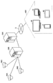
- FIG. 1 is a diagram illustrating an overall configuration of a camera system according to an embodiment of the present disclosure.
- the camera system includes a large number of fixed cameras 10A to 10C, a local server 30, and a cloud server 38.
- the fixed cameras 10A to 10C are a surveillance camera, a fixed point camera, or the like that is attached to a ceiling, a wall, or the like in a specific place and continuously images the surroundings. Further, the fixed cameras 10A to 10C can communicate with an information processing terminal (for example, the smartphone 2) possessed by the subject (user 3) and acquire device information.
- an information processing terminal for example, the smartphone 2 possessed by the subject (user 3) and acquire device information.
- the local server 30 manages a large number of fixed cameras 10A to 10C. Further, the local server 30 is installed in a place close to these camera groups. In the example shown in FIG. 1, only one camera group (fixed cameras 10A to 10C) and a pair of local servers 30 that manage them are shown, but for example, local cameras that manage camera groups installed in a theme park are shown. There may be a plurality of local servers, such as a server and a local server that manages a camera group installed in a shopping mall. The plurality of local servers also function as gateways for communication with an external network and communicate with the cloud server 38.
- the local server 30 transfers the captured images acquired from the fixed cameras 10A to 10C to the cloud server 38.
- the cloud server 38 stores the information disclosure attribute (privacy level) of the smartphone 2.
- the information disclosure attribute can be registered by the user 3 in advance, for example.
- the cloud server 38 displays the captured image transferred from the local server 30 in response to an access from an external monitor such as the display device 40 of a general home 400, a PC (Personal Computer) 41, a tablet terminal 42, or the smartphone 2. provide.
- an external monitor such as the display device 40 of a general home 400, a PC (Personal Computer) 41, a tablet terminal 42, or the smartphone 2. provide.
- the local server 30 and the cloud server 38 are separate devices, but the local server 30 may include the function of the cloud server 38.
- a display device 40 (a television device, a home projector, a wall display, etc.) of a general home 400 is connected to the network 5 by DSL (Digital Subscriber Line). Further, the PC 41, the tablet terminal 42, the smartphone 2, and the like are connected to the network 5 through a mobile phone network. Thereby, the user 3 accesses the cloud server 38 or the local server 30 from the external monitor such as the display device 40, the PC 41, the tablet terminal 42, or the smartphone 2 after returning home, with the image captured by the user 3 with the fixed cameras 10 ⁇ / b> A to 10 ⁇ / b> C when going out. You can browse.
- DSL Digital Subscriber Line
- the conventional camera system includes fixed cameras 50A to 50C, a local server 500, and a cloud server 520.
- the fixed cameras 50A to 50C transmit the captured images as they are to the local server 500, and transfer the captured images collected by the local server 500 to the cloud server 520 as they are.
- the captured image transferred to the cloud server 520 is provided in response to an access from an external monitor such as the display device 40, and the user can browse images captured by the fixed cameras 50A to 50C by the display device 40.
- the images captured by the fixed cameras 50A to 50C are provided to the external monitor as they are without any processing, so that personal information such as when and where the person was is provided to a third party. It was known. In addition, there is no problem for the user of the service of providing a captured image by the camera system, but a captured image in which a person who is near the user is reflected is also provided. I was concerned about the problem.
- the processing of deleting an object (part where privacy infringement is feared) that can identify an individual is performed on the captured image, and the image is distributed to prevent privacy infringement and the captured image.
- the image is distributed to prevent privacy infringement and the captured image.
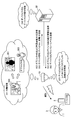
- FIG. 3 is a diagram for explaining an outline when a captured image is acquired in the camera system according to the present embodiment.
- the fixed camera 10 captures the user 3 and acquires a captured image 300.
- the fixed camera 10 cuts out a dynamic object object such as a person from the captured image 300 and separates it into an object part (hereinafter referred to as an object image 302) and another part (hereinafter referred to as a background image 301). Is performed (step S1). Further, the fixed camera 10 assigns an object ID to the separated object image 302.
- the background image 301 is an image in which an object that can identify an individual (a portion that is in danger of privacy infringement) is missing, and the missing portion is, for example, a silhouette (a portion in which an object is hollowed out) as shown in FIG.
- a non-privacy image such as a predetermined avatar or a fictional person may be synthesized, or mosaic processing or blurring processing may be performed.
- the fixed camera 10 transmits the object ID and the background image 301 to the local server 30 (step S2).
- the fixed camera 10 communicates with an information processing terminal (for example, the smartphone 2) possessed by the user 3 by constantly trying to communicate with an information processing terminal existing in the vicinity. It is possible to acquire device information.
- the device information includes a device ID (for example, a telephone number, a user name, or a password).
- the fixed camera 10 also extracts distance information between the fixed camera 10 and the smartphone 2 from the signal strength, the signal transmission / reception delay time, and the like based on communication with the smartphone 2.
- the fixed camera 10 transmits the device ID and distance information as device information to the local server 30 (step S3).
- the local server 30 associates the object (object ID) corresponding to the missing portion of the background image 301 and the device ID based on the device information, the background image 301, and the object ID received from the fixed camera 10 (steps). S4). Specifically, the local server 30 uses the distance information (distance between the fixed camera 10 and the smartphone 2) included in the device information to determine which object object of the background image 301 is the owner of the smartphone 2 indicated by the device ID. It is judged whether it is. At this time, the object portion that can identify the user 3 is missing, but can be recognized as a missing portion (silhouette or mosaic processing portion).
- the local server 30 transmits the association information (mapping information) between the object ID and the device ID to the fixed camera 10 (step S5).
- the local server 30 acquires an information disclosure attribute (hereinafter referred to as a privacy level) of the device (smart phone 2) with which the fixed camera 10 has communicated, and sends this to the fixed camera 10. Transmit (step S6).
- the privacy level is set, for example, as to whether or not to disclose (publish) a user's own image (an object that can identify the user) included in the captured image when the privacy level is registered in advance by the user and captured by the fixed camera 10. Information.
- a disclosure level such as whether to disclose only to oneself or to disclose to a specific other person.
- the fixed camera 10 deletes the object image 302 corresponding to the object ID associated with the device ID of the device according to the privacy level of the device transmitted from the local server 30. For example, when the privacy level of the smartphone 2 possessed by the user 3 is set to “high” (cannot be disclosed), the fixed camera 10 is connected to the object image 302 (separated from the captured image 300) that is associated with the smartphone 2. 3) is deleted. Thereby, by setting the privacy level to “high” in advance, even when the image is captured by the fixed camera 10, information for identifying itself (its own captured image) can be deleted.
- the fixed camera 10 stores the object image 302 associated with the smartphone 2.
- the user 3 can view the captured image captured by the fixed camera 10 from an external monitor later. Hereinafter, browsing of the captured image will be described with reference to FIG.
- FIG. 4 is a diagram for explaining an outline when browsing a captured image in the camera system according to the present embodiment.
- the user 3 requests the local server 30 to browse the captured image from the display device 40 (an example of an external monitor).
- the device ID for example, a telephone number, a user name, or a password
- the camera system according to the present embodiment includes the cloud server 38, and the display device 40 installed in the general home 400 is connected to the local server 30 via the cloud server 38 connected to the network 5.
- the cloud server 38 is not shown in the schematic diagram shown in FIG.
- the local server 30 makes an inquiry to the fixed camera 10A that stores the object image 302 indicated by the object ID associated with the object ID (step S12). .
- the fixed camera 10A transmits the object image 302 indicated by the object ID associated with the device ID to the local server 30 (step S13).
- the local server 30 combines the stored background image 301 and the received object image 302 to generate a restored image 303 and transmits it to the display device 40. Thereby, the user 3 can browse the restored image 303 in which the user 3 is reflected on the display device 40.
- information for identifying an individual can be deleted from a captured image captured by the fixed camera 10 according to the privacy level.
- a user who wants to view the captured image later can set the privacy level to a low level so that the separated captured image (object image 302) is stored in the fixed camera 10, and he / she can restore the captured image later by restoration processing.
- the local server 30 does not perform restoration processing and provides a background image 301 (an image in which the object image 302 is missing) to a person who does not have access authority (a person who is not made public due to the privacy level). By doing so, the privacy of the user can be protected.
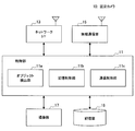
- FIG. 5 is a block diagram illustrating a basic configuration example of the fixed camera 10 according to the present embodiment.
- the fixed camera 10 includes a control unit 11, a network I / F (interface) 13, a wireless communication unit 15, an imaging unit 17, and a storage unit 19.
- the control unit 11 includes, for example, a microcomputer including a CPU (Central Processing Unit), a ROM (Read Only Memory), a RAM (Random Access Memory), a nonvolatile memory, and an interface unit, and controls each configuration of the fixed camera 10. To do.
- a microcomputer including a CPU (Central Processing Unit), a ROM (Read Only Memory), a RAM (Random Access Memory), a nonvolatile memory, and an interface unit, and controls each configuration of the fixed camera 10. To do.
- the control unit 11 functions as an object detection unit 11a, a storage control unit 11b, and a communication control unit 11c.
- the object detection unit 11 a detects an object that can identify an individual from the image data captured by the imaging unit 17. Specifically, the object detection unit 11a detects and extracts a human object from the dynamic object objects. The object detection unit 11a gives an object ID to the detected object.
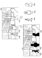
- the object detection unit 11 a detects human objects 310 a, 310 b, and 310 c that are dynamic objects in the captured image 300 captured by the fixed camera 10. Since the fixed camera 10 continuously captures the surroundings, the object detection unit 11a recognizes an object that does not move (background of buildings, trees, roads, etc.) and an object that moves (person, car, etc.). Is possible.
- object images 302a to 302c including information that can identify an individual are extracted from the captured image 300, and a background image 301 lacking the object images 302a to 302c is generated.
- the background image 301 as shown in FIG. 6, the areas corresponding to the object images 302a to 302c are silhouettes (shadow objects) 320a to 320c, and information that can identify an individual is missing.
- the storage control unit 11b performs control so as to record in the storage unit 19 information that can restore the object that is missing from the captured image.
- the storage control unit 11b stores the object image 302 detected (extracted) from the captured image 300 by the object detection unit 11a in the storage unit 19.
- the storage control unit 11b restores them.
- Information is stored in the storage unit 19.
- the storage destination of the information that can restore the object lost from the captured image is not limited to the storage unit 19 built in the fixed camera 10, and may be an external storage unit.
- the storage control unit 11b stores the association information between the device ID and the object ID transmitted from the local server 30 in the storage unit 19.
- the communication control unit 11c has a function of controlling communication with an external device.
- the communication control unit 11 c uses the background image 301 in which the object detection unit 11 a lacks information (object image 302) relating to an object that can identify an individual from the captured image 300 and the object ID assigned to the object image 302. Control is performed to transmit to the local server 30 via the network I / F 13.
- the communication control unit 11 c transmits device information acquired from the information processing terminal (for example, the smartphone 2) via the wireless communication unit 15 to the local server 30 via the network I / F 13.
- the communication control unit 11c includes distance information indicating the distance between the fixed camera 10 and the information processing terminal in addition to the device ID.
- the communication control unit 11c receives the association information between the device ID and the object ID from the local server 30. Further, in response to a request from the local server 30, the communication control unit 11 c extracts from the storage unit 19 the object image 302 to which the object ID associated with the device ID included in the request is added, and the local server 30. Control to reply to.
- the network I / F 13 has a function of connecting to the Internet and communicating with the local server 30.
- the wireless communication unit 15 performs wireless communication with information processing terminals (portable devices) existing in the vicinity.
- the communication means for example, Wi-Fi (registered trademark), Bluetooth (registered trademark), infrared communication or the like is used.
- the wireless communication unit 15 since the wireless communication unit 15 always tries to communicate with the information processing terminal, when the information processing terminal enters the imaging range of the fixed camera 10, the wireless communication unit 15 detects this instantaneously, and the device information from the information processing terminal Can be obtained.
- the information processing terminal is detected by, for example, periodically transmitting a beacon signal or confirming whether there is a response to the probe signal. Further, when detecting the information processing terminal, information according to the distance between the fixed camera 10 and the information processing terminal (hereinafter also referred to as distance information) is extracted from the signal strength, the signal transmission / reception delay time, and the like.
- the imaging unit 17 photoelectrically converts imaging light obtained by a lens system including an imaging lens, a diaphragm, a zoom lens, and a focus lens, a drive system that causes the lens system to perform a focus operation and a zoom operation, and the lens system.
- a solid-state imaging device array that generates an imaging signal.
- the solid-state imaging device array may be realized by a CCD (Charge Coupled Device) sensor array or a CMOS (Complementary Metal Oxide Semiconductor) sensor array, for example.
- the imaging unit 17 continuously images the surroundings and outputs the captured image to the control unit 11.
- the storage unit 19 stores a program for executing various processes by the control unit 11.
- the storage unit 19 stores the object image detected by the object detection unit 11a.
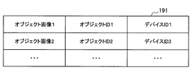
- a data configuration example of the storage unit 19 will be described with reference to FIG.
- FIG. 7 shows a data structure in which an object image is associated with an object ID and a device ID.
- object image 1 is associated with object ID1 and device ID1.
- the object ID is identification information given when an object image is detected from the captured image 300 by the object detection unit 11a.
- the device ID is stored based on the association information between the object ID and the device ID transmitted from the local server 30.
- the basic configuration of the fixed camera 10 according to the present embodiment has been described above. Next, the basic configuration of the local server 30 included in the camera system according to the present embodiment will be described.
- FIG. 8 is a block diagram illustrating a configuration example of the local server 30.
- the local server 30 includes a control unit 31, a network I / F 33, and a storage unit 35.
- the local server 30 starts managing the object ID.
- the control unit 31 is constituted by, for example, a microcomputer including a CPU, ROM, RAM, nonvolatile memory, and interface unit, and controls each configuration of the local server 30.
- control unit 31 functions as an association unit 31a, a storage control unit 31b, a communication control unit 31c, and a restoration unit 31d.
- the associating unit 31a associates the object ID transmitted from the fixed camera 10 with the device ID. Specifically, for example, the associating unit 31a performs associating based on the time-series change of the device distance information and the movement of the tracked object silhouette.
- the associating unit 31a tracks the movement of the silhouette (shadow object) 320 of the object, which is the portion of the background image 301 that is continuously transmitted from the fixed camera 10 that lacks information that identifies the individual. At this time, the associating unit 31a can also estimate the distance between the fixed camera 10 and the silhouette as the first distance based on image processing or the like. Similarly, when the background image 301 is continuously transmitted from the plurality of fixed cameras 10, the associating unit 31 a tracks the movement of the silhouette 320 in each background image 301 and captures the same object. It is also possible to detect the background image 301.
- the associating unit 31a includes the distance information (the change in the first distance) of the silhouette (shadow object) 320 and the distance information (the distance between the fixed camera 10 and the object included in the device information sent from the fixed camera 10). It is possible to determine which silhouette corresponds to the device information by comparing the time-series change of the second distance). Then, the associating unit 31a associates the corresponding silhouette object ID with the device ID included in the device information. Thereby, the association between the owner of the device and the object image obtained by capturing the owner with the camera is realized.
- the association between the object ID and the device ID according to the present embodiment is not limited to the case based on the distance information.
- the attribute according to the device ID face recognition (face feature pattern information), QR code (registered trademark) An image marker such as) may be used. That is, if the device ID includes “sex” and “age” as owner attributes, and the object ID also includes “sex” and “age” of the target object recognized by the fixed camera 10, these are compared.
- the associating unit 31a can determine which object corresponds to which device.
- the associating unit 31a determines which object is which device. Can be determined.
- the storage control unit 31 b performs control so that the association information between the object ID and the device ID by the association unit 31 a is stored in the storage unit 35. At this time, the storage control unit 31b stores the object ID in association with the information of the camera that captured the object and the time information. Further, when the information disclosure attribute (privacy level) of the device is acquired from the cloud server 38, the storage control unit 31b controls to store the device ID and the information disclosure attribute in the storage unit 35 in association with each other.
- the communication control unit 31c has a function of controlling communication with an external device via the network I / F 33. For example, the communication control unit 31 c receives the background image 301, the object ID, and the device information from the fixed camera 10. Further, the communication control unit 31 c transmits the association information between the object ID and the device ID to the fixed camera 10.
- the communication control unit 31c controls to inquire the cloud server 38 about the information disclosure attribute corresponding to the device ID received from the fixed camera 10. In addition, the communication control unit 31 c controls to transmit the information disclosure attribute corresponding to the device ID to the fixed camera 10. Further, the communication control unit 31c controls to transmit the original captured image restored by the restoration unit 31d described later to the local server 30.
- the restoration unit 31d restores original image data including information that can identify an individual based on information received from the fixed camera 10 that can restore an object. For example, the restoration unit 31d combines the object image 302 acquired from the fixed camera 10 with the background image 301 already stored in the storage unit 35, and generates an original captured image (hereinafter also referred to as a restored image).
- the network I / F 33 has a function of connecting to the Internet and communicating with the fixed camera 10 or the cloud server 38.
- the network I / F 33 can also communicate with the display device 40, the smartphone 2, and the like via the network 5.
- the storage unit 35 stores a program for executing various processes by the control unit 31.
- the storage unit 35 stores information related to the object ID received via the network I / F 33 and information related to the device ID.
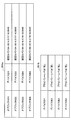
- a data configuration example of the storage unit 35 will be described with reference to FIG.
- FIG. 9 shows a data configuration example of the object ID related information 351a.
- the object ID is associated with the device ID, the storage location of the target object, and the imaging date / time.
- the object ID1 is associated with the device ID1
- the object image indicated by the object ID1 is stored in the fixed camera 10A (storage location information)
- the object image is 10:30 on February 17, 2014. The fact that the image was captured at 45 minutes (image date and time information) is associated.
- the device ID is associated with the privacy level (device disclosure attribute).
- the first record of the device ID related information 351b indicates that the privacy level of the device ID 1 is “low”.
- the configuration of the local server 30 according to the present embodiment has been specifically described above. Next, the operation process of this embodiment will be specifically described.
- Action processing In the camera system according to this embodiment, as outlined with reference to FIGS. 3 and 4, the process at the time of acquiring a captured image (see FIG. 3) and the process at the time of browsing the captured image (see FIG. 4). And execute.
- the processing at the time of acquiring a captured image will be specifically described with reference to FIGS. 10 to 12, and the processing at the time of browsing the captured image will be specifically described with reference to FIG.
- FIG. 10 is a sequence diagram showing processing (separation processing) at the time of captured image acquisition.
- the imaging unit 17 of the fixed camera 10 acquires a captured image (camera imaging).
- step S106 the object detection unit 11a detects a new object from the captured images continuously captured by the imaging unit 17.
- step S109 the object detection unit 11a assigns an object ID to the detected new object, and adds the object to the subsequent separation processing target (registration). ) In this way, by adding a new object to the separation processing target each time a new object is detected, the object can be continuously separated from captured images that are continuously captured.
- step S112 the object detection unit 11a separates (extracts) the object to be separated from the captured image, and deletes information for identifying an individual from the captured image.
- the object detection unit 11a separates the plurality of objects 310a to 310c from the captured image 300 as illustrated in FIG.
- step S115 the storage control unit 11b controls to store the separated object in the storage unit 19.
- the separated object is stored in association with the device ID.
- the separated object image is temporarily stored even when the device ID is not associated with the device ID. The association with the device ID can be performed later.
- step S118 the communication control unit 11c sends the background image 301 from which the object has been separated (the information specifying the individual is missing) and the object ID assigned to the separated object from the network I / F 13 to the local server 30. Send.
- step S121 the storage control unit 31b of the local server 30 stores the object ID received from the fixed camera 10 via the network I / F 33 in the storage unit 35.
- step S124 the associating unit 31a tracks a shadow object (area corresponding to the separated object) corresponding to the object ID in the background image 301 received from the fixed camera 10. Since the background image 301 is continuously transmitted from the fixed camera 10 or the background image 301 is periodically / irregularly transmitted as a moving image for a fixed time, the associating unit 31a includes the shadow object in the background image 301. Follow the movement.
- FIG. 11 is a sequence diagram showing a process (linking process) at the time of acquiring a captured image according to the present embodiment.
- the fixed camera 10 receives device information of an information processing terminal (for example, the smartphone 2) existing in the vicinity by the wireless communication unit 15, and detects a new device.
- the fixed camera 10 always tries to communicate with surrounding information processing terminals. Therefore, when the information processing terminal enters the imaging range of the fixed camera 10, this is detected instantaneously, and information processing is performed. Device information can be acquired from the terminal.
- step S130 the communication control unit 11c controls the network I / F 13 to transmit new device information to the local server 30.
- the communication control unit 11c controls the network I / F 13 to transmit new device information to the local server 30.
- FIG. 11 a case where new device information is transmitted only once is illustrated, but it may be transmitted a plurality of times due to a change in distance information or the like. That is, the fixed camera 10 continues to extract distance information with new device information for a certain period of time, and continuously transmits this information to the local server 30.
- step S133 the associating unit 31a of the local server 30 associates the device ID included in the received device information with the object ID. Specifically, the associating unit 31a compares the time series change of the distance information with respect to the fixed camera 10 included in the device information and the movement of the silhouette 320 included in the background image 301 (the movement tracked in S124). Thus, the silhouette 320 (shadow object) of the owner of the device is determined. Then, the associating unit 31a associates the device ID with the object ID of the corresponding silhouette 320.
- step S139 the communication control unit 31c controls to transmit the association information between the object ID and the device ID to the fixed camera 10.
- step S142 the storage control unit 31b of the fixed camera 10 refers to the association information received from the local server 30, and controls to store the object ID and the device ID in association with the object image separated in S112. To do.
- the process shown in S142 may be performed in combination with S115. Also, as will be described later, since the processes shown in FIGS. 10 to 12 are repeatedly performed, the device ID is subsequently associated with the same object (S127 / No, S142).
- FIG. 12 is a sequence diagram illustrating a process (deletion process) when a captured image is acquired.
- the process shown in FIG. 12 can be processed in parallel with the processes shown in FIGS.
- step S145 when the communication control unit 11c of the fixed camera 10 receives new device information (S127 / Yes), the device information is disclosed via the network I / F 13. Queries the local server 30 for attributes.
- step S148 the control unit 31 of the local server 30 determines whether or not the information disclosure attribute of the device inquired from the fixed camera 10 is known.
- step S151 when the information disclosure attribute of the inquired device is not stored in the storage unit 19 (S148 / No), in step S151, the communication control unit 31c sends the device information disclosure attribute of the device to the cloud server 38. Make an inquiry.
- step S154 the cloud server 38 returns the information disclosure attribute of the device in response to the inquiry from the local server 30.
- step S157 when the information disclosure attribute is received (S154), or when the information disclosure attribute is known (S148 / Yes), in step S157, the storage control unit 31b of the local server 30 determines the device ID and the information disclosure attribute ( Association information with “privacy level” is stored in the storage unit 19.
- step S160 the communication control unit 31c transmits the privacy level of the device corresponding to the inquiry to the fixed camera 10.
- the storage control unit 11b of the fixed camera 10 performs deletion control of the object image (see S142 above) associated with the device ID of the device according to the received privacy level of the device. Specifically, the storage control unit 11b determines whether the privacy level of the device is high or low.
- the privacy level “high” indicates that disclosure is impossible
- the privacy level “low” indicates that disclosure is possible.
- a user to be disclosed may be further specified. Specifically, for example, a device ID of a user who can be disclosed is specified.
- step S166 the storage control unit 11b performs control to delete the object image associated with the device ID of the device from the storage unit 19. To do. Further, the storage control unit 11b performs control so as not to store information related to the object. Thereby, when the user 3 sets the privacy level to “high” in advance, it is possible to delete the information (the captured image) identifying the user himself / herself when the image is captured by the fixed camera 10.
- the storage control unit 11b marks the object as a target that may be stored in the storage unit 19, and controls to store information related to the object thereafter.
- the processing at the time of obtaining a captured image according to the present embodiment has been specifically described above with reference to FIGS. Note that the processes shown in FIGS. 10 to 11 can be repeatedly performed continuously. Further, instead of S160 to S163, the local server 30 may determine whether the privacy level is high or low, and if it is “high”, a request for deleting the corresponding object image may be sent to the fixed camera 10. Next, processing at the time of browsing a captured image according to the present embodiment will be described with reference to FIG.
- FIG. 13 is a sequence diagram illustrating processing at the time of browsing a captured image.
- the local server 30 and the display apparatus 40 communicate via the network 5 and the cloud server 38
- the cloud server 38 is abbreviate
- the display device 40 makes a browsing request to the local server 30.
- the browsing request includes information necessary for specifying an image to be browsed, and includes, for example, time, place, and device ID. For example, when the user 3 wants to see a photograph at a predetermined tourist spot visited yesterday from 3:00 to 5:00, in addition to the date and time and location information, the user ID of the device that the user 3 has is displayed on the display device 40. Enter and send a browsing request.
- step S206 the local server 30 receives a browsing request from the display device 40.
- step S209 the storage control unit 31b of the local server 30 extracts the background image 301 at the time and place specified by the browsing request from the storage unit 35.
- step S212 the storage control unit 31b determines whether or not the device ID included in the browsing request is managed, and checks whether the object ID associated with the device ID exists. .
- step S215 the communication control unit 31c controls to transmit the extracted background image 301 to the display device 40. Since the background image 301 is in a state in which information that can identify an individual is missing, even if it is transferred to an unspecified number of display devices 40, a privacy problem does not occur.
- step S218 the communication control unit 31c displays an image to be reproduced with respect to the fixed camera 10 storing the object image corresponding to the object ID.
- Information time, place, device ID, object ID, etc.
- the inquiry can be made as an inquiry for requesting transmission of an object image when the privacy level of the device ID corresponding to the object ID is “low”.
- step S ⁇ b> 221 the communication control unit 11 c of the fixed camera 10 extracts the target object image 302 from the storage unit 19 based on the information included in the inquiry from the local server 30 and transfers it to the local server 30. .
- step S224 the restoration unit 31d of the local server 30 synthesizes the object image 302 received from the fixed camera 10 with the background image 301 stored in the storage unit 35 to obtain the original captured image (restored image). ) Is generated.
- the restoration unit 31d combines the object image 302a with the background image 301 to generate a restored image. Accordingly, it is possible to generate an image in which only information that can specify the corresponding user (object image 302a) is restored while information that can specify the other users (object images 302b and 302c) is missing. Thereby, the problem of privacy of other users does not occur.
- step S227 the communication control unit 31c transmits the restored image to the display device 40.
- step S230 the display device 40 displays the received restored image.
- the camera system distributes an image after performing a process of deleting an object (part where privacy infringement is feared) that can identify an individual from a captured image, Both prevention of privacy infringement and distribution of captured images can be achieved.
- the information (restored image) that is restored and transferred to the external monitor includes only information on the object object that is permitted to be disclosed by the information disclosure attribute (privacy level) registered in association with the device ID. Therefore, the privacy of others reflected in the image can be secured.
- a computer program for causing the functions of the fixed camera 10 and the local server 30 to be performed on hardware such as the CPU, ROM, and RAM incorporated in the fixed camera 10 and the local server 30 described above.
- a computer-readable storage medium storing the computer program is also provided.
- the assignment of the object ID to the separated object may be performed on the local server 30 side.
- this technique can also take the following structures.
- An object detection unit for detecting an object that can identify an individual from the image data captured by the imaging unit;
- a storage control unit for storing information capable of restoring the object in a storage unit;
- a communication control unit that controls to transfer image data generated by deleting information on the object that can identify the individual from the image data to a server;
- An information processing apparatus comprising: (2) The communication control unit further transfers an object ID corresponding to the object to the server, The information processing apparatus according to (1), wherein the storage control unit associates the object ID and stores information related to the object.
- the information processing apparatus further includes a wireless communication unit capable of communicating with a wireless terminal, The information processing apparatus according to (2), wherein the communication control unit transfers a device ID of the wireless terminal detected by the wireless communication unit and information regarding a distance to the wireless terminal to a server.
- the privacy level is managed in units of device IDs, the object ID transferred to the server and the device ID are linked according to the distance to the wireless terminal,
- the communication control unit receives, as an information processing apparatus storing information capable of restoring an object corresponding to an object ID having a high privacy level, a request for deleting information capable of restoring the object from the server,
- the information processing apparatus according to (3) wherein the storage control unit deletes information capable of restoring the object from the storage unit in response to the deletion request.
- the communication control unit transfers information that can restore the object corresponding to the object ID read from the storage unit in response to the browsing request including the object ID received from the server to the server.
- the information processing apparatus according to 3).
- a communication control unit that receives, from an external device, image data in which information about an object that can identify an individual from image data captured by the imaging unit is deleted;
- a storage control unit that assigns an object ID to an area corresponding to an object that can identify the individual and stores the object ID in association with the image data; With The information processing apparatus, wherein the communication control unit controls to return the object ID to the external apparatus.
- the communication control unit receives the device ID of the wireless terminal detected by the external device from surrounding wireless terminals
- the information processing apparatus includes: The information processing apparatus according to (6), further including an association unit that associates an object ID and the device ID with an area corresponding to an object that can identify the individual.
- the communication control unit receives the device ID of the wireless terminal received by the external device from surrounding wireless terminals, and information on the distance between the external device and the wireless terminal,
- the associating unit is estimated from information relating to a first distance indicating a distance between the external device and a region corresponding to an object that can identify the individual in the image data, and a distance between the external device and the wireless terminal.
- the information processing apparatus according to (7), wherein the object ID and the device ID are associated with each other.
- a privacy level is set for the device ID, The information processing apparatus according to (8), wherein the association unit sets a privacy level of the object ID based on a device ID. (10) The information processing apparatus according to (9), wherein the communication control unit transmits a deletion request to an external apparatus corresponding to the object ID when the privacy level is high. (11) The communication control unit receives a browsing target time, information that can identify the external device, and a device ID as a browsing request from the outside, The storage control unit receives image data corresponding to the time to be browsed from among image data received from an external device identified by information that can identify the external device and lacking information on an object that can identify an individual.
- the communication control unit transmits request information for requesting information capable of restoring the object corresponding to the object ID when the privacy level set in the object ID associated with the device ID is low.
- Receiving information capable of restoring the object returned in response to the request information The information processing apparatus includes: Based on the image data extracted from the storage unit and information that can restore the received object, further comprises a restoration unit that restores original image data including information that can identify an individual, The information processing apparatus according to (9), wherein the communication control unit transmits the original image data restored by the restoration unit to the browsing request source.
- An object detection unit for detecting an object that can identify an individual from the image data captured by the imaging unit; A storage control unit for storing information capable of restoring the object in a storage unit; A communication control unit that controls to transfer image data generated by deleting information on the object that can identify the individual from the image data to a server; A storage medium that stores a program for functioning as a computer.
Landscapes
- Engineering & Computer Science (AREA)
- Multimedia (AREA)
- Signal Processing (AREA)
- Physics & Mathematics (AREA)
- General Physics & Mathematics (AREA)
- Theoretical Computer Science (AREA)
- Astronomy & Astrophysics (AREA)
- Computing Systems (AREA)
- General Engineering & Computer Science (AREA)
- Studio Devices (AREA)
- Telephonic Communication Services (AREA)
Abstract
Description
1.本開示の一実施形態によるカメラシステムの概要
2.基本構成
2-1.固定カメラの構成例
2-2.ローカルサーバの構成例
3.動作処理
3-1.撮像画像取得時の処理
3-2.撮像画像閲覧時の処理
4.まとめ
まず、本開示の一実施形態によるカメラシステムの概要について図1を参照して説明する。図1は、本開示の一実施形態によるカメラシステムの全体構成を示す図である。
ここで、従来のカメラシステムについて図2を参照して説明する。図2に示すように、従来のカメラシステムは、固定カメラ50A~50Cと、ローカルサーバ500と、クラウドサーバ520と、を含む。
<2-1.固定カメラの構成例>
次に、本実施形態によるカメラシステムに含まれる固定カメラ10の構成について図5を参照して説明する。図5は、本実施形態による固定カメラ10の基本構成例を示すブロック図である。
ここで、図6を参照してオブジェクト検出部11aによるオブジェクトの検出について説明する。図6に示すように、固定カメラ10により撮像された撮像画像300に対して、オブジェクト検出部11aは、動的物体である人物のオブジェクト310a、310b、310cを検出する。固定カメラ10は周囲を継続的に撮像しているため、オブジェクト検出部11aは、動きのない物体(建物、木、道等の背景)と、動きのある物体(人物、車等)とを認識することが可能である。
図8は、ローカルサーバ30の構成例を示すブロック図である。図8に示すように、ローカルサーバ30は、制御部31、ネットワークI/F33、および記憶部35を有する。ローカルサーバ30は、固定カメラ10からオブジェクトIDを受信すると、当該オブジェクトIDの管理を開始する。
また、記憶制御部31bは、クラウドサーバ38からデバイスの情報開示属性(プライバシーレベル)を取得した場合、デバイスIDと当該情報開示属性とを対応付けて記憶部35に記憶するよう制御する。
本実施形態によるカメラシステムでは、図3および図4を参照して概要を説明したように、撮像画像の取得時における処理(図3参照)と、撮像画像の閲覧時における処理(図4参照)とを実行する。以下、撮像画像取得時の処理について図10~図12を参照して具体的に説明し、次いで撮像画像閲覧時の処理について図13を参照して具体的に説明する。
図10は、撮像画像取得時の処理(分離処理)を示すシーケンス図である。図10に示すように、まず、ステップS103において、固定カメラ10の撮像部17は、撮像画像の取得(カメラ撮影)を行う。
図13は、撮像画像閲覧時の処理を示すシーケンス図である。なおローカルサーバ30と表示装置40は、ネットワーク5およびクラウドサーバ38を介して通信を行うが、図13に示すシーケンス図ではクラウドサーバ38を省略する。
上述したように、本開示の実施形態によるカメラシステムでは、撮像画像に対して個人を特定できるオブジェクト(プライバシー侵害が懸念される部分)を欠落させる処理を行った上で画像を流通させることで、プライバシー侵害の防止と撮像画像の流通との両立を図ることができる。
(1)
撮像部により撮像された画像データから、個人を特定できるオブジェクトを検出するオブジェクト検出部と、
前記オブジェクトを復元可能な情報を記憶部に記憶する記憶制御部と、
前記画像データから前記個人を特定できるオブジェクトに関する情報を欠落させて生成された画像データを、サーバに転送するよう制御する通信制御部と、
を備える、情報処理装置。
(2)
前記通信制御部は、さらに前記オブジェクトに対応するオブジェクトIDをサーバに転送し、
前記記憶制御部は、前記オブジェクトIDを紐づけて、前記オブジェクトに関する情報を記憶する、前記(1)に記載の情報処理装置。
(3)
前記情報処理装置は、無線端末と通信可能な無線通信部をさらに備え、
前記通信制御部は、前記無線通信部により検出された無線端末のデバイスIDと、当該無線端末までの距離に関する情報とをサーバに転送する、前記(2)に記載の情報処理装置。
(4)
前記サーバでは、デバイスID単位でプライバシーレベルを管理し、前記サーバに転送されたオブジェクトIDと前記デバイスIDが前記無線端末までの距離に応じて紐づけられ、
前記通信制御部は、前記プライバシーレベルが高いオブジェクトIDに対応するオブジェクトを復元可能な情報を記憶している情報処理装置として、前記サーバから当該オブジェクトを復元可能な情報の削除要求を受信し、
前記記憶制御部は、前記削除要求に応じて、当該オブジェクトを復元可能な情報を前記記憶部から削除する、前記(3)に記載の情報処理装置。
(5)
前記通信制御部は、前記サーバから受信したオブジェクトIDを含む閲覧要求に応じて前記記憶部から読み出された当該オブジェクトIDに対応するオブジェクトを復元可能な情報を、前記サーバに転送する、前記(3)に記載の情報処理装置。
(6)
撮像部により撮像された画像データから個人を特定できるオブジェクトに関する情報を欠落させた画像データを、外部装置から受信する通信制御部と、
前記個人を特定できるオブジェクトに対応する領域にオブジェクトIDを割り当て、前記画像データと対応付けて記憶部に記憶する記憶制御部と、
を備え、
前記通信制御部は、前記オブジェクトIDを前記外部装置に返信するよう制御する、情報処理装置。
(7)
前記通信制御部は、前記外部装置が周辺の無線端末から検出した当該無線端末のデバイスIDを受信し、
前記情報処理装置は、
前記個人を特定できるオブジェクトに対応する領域にオブジェクトIDと前記デバイスIDとを紐づける紐付部をさらに備える、前記(6)に記載の情報処理装置。
(8)
前記通信制御部は、前記外部装置が周辺の無線端末から受信した当該無線端末のデバイスIDと、前記外部装置と前記無線端末間の距離に関する情報を受信し、
前記紐付部は、前記画像データ内の前記個人を特定できるオブジェクトに対応する領域と前記外部装置間の距離を示す第1の距離と、前記外部装置と前記無線端末間の距離に関する情報から推定される第2の距離とを比較して、前記オブジェクトIDと前記デバイスIDとを紐づける、前記(7)に記載の情報処理装置。
(9)
前記デバイスIDには、プライバシーレベルが設定され、
前記紐付部は、デバイスIDに基づいて、前記オブジェクトIDのプライバシーレベルを設定する、前記(8)に記載の情報処理装置。
(10)
前記通信制御部は、前記プライバシーレベルが高い場合、前記オブジェクトIDに対応する外部装置に対して削除要求を送信する、前記(9)に記載の情報処理装置。
(11)
前記通信制御部は、外部から閲覧要求として、閲覧対象の時刻、前記外部装置を特定可能な情報、およびデバイスIDを受信し、
前記記憶制御部は、当該外部装置を特定可能な情報によって特定された外部装置から受信した、個人を特定できるオブジェクトに関する情報を欠落させた画像データのうち、前記閲覧対象の時刻に対応する画像データを前記記憶部から抽出し、
前記通信制御部は、前記デバイスIDに紐付けられている前記オブジェクトIDに設定された前記プライバシーレベルが低いとき、前記オブジェクトIDに対応するオブジェクトを復元可能な情報を要求する要求情報を送信するとともに、前記要求情報に対応して返信されたオブジェクトを復元可能な情報を受信し、
前記情報処理装置は、
前記記憶部から抽出した画像データと、前記受信したオブジェクトを復元可能な情報とに基づいて、個人を特定できる情報を含む元画像データを復元する復元部をさらに備え、
前記通信制御部は、前記閲覧要求元に、前記復元部により復元された元画像データを送信する、前記(9)に記載の情報処理装置。
(12)
コンピュータを、
撮像部により撮像された画像データから、個人を特定できるオブジェクトを検出するオブジェクト検出部と、
前記オブジェクトを復元可能な情報を記憶部に記憶する記憶制御部と、
前記画像データから前記個人を特定できるオブジェクトに関する情報を欠落させて生成された画像データを、サーバに転送するよう制御する通信制御部と、
として機能させるためのプログラムを記憶した、記憶媒体。
(13)
撮像部により撮像された画像データから個人を特定できるオブジェクトに関する情報を欠落させた画像データを、外部装置から受信することと、
前記個人を特定できるオブジェクトに対応する領域にオブジェクトIDを割り当て、前記画像データと対応付けて記憶部に記憶することと、
前記オブジェクトIDを前記外部装置に返信するよう制御すること、
を含む、制御方法。
3 ユーザ
5 ネットワーク
10、10A~10C 固定カメラ
11 制御部
11a オブジェクト検出部
11b 記憶制御部
11c 通信制御部
13 ネットワークI/F
15 無線通信部
17 撮像部
19 記憶部
30 ローカルサーバ
31 制御部
31a 紐付部
31b 記憶制御部
31c 通信制御部
31d 復元部
33 ネットワークI/F
35 記憶部
38 クラウドサーバ
40 表示装置
41 PC
42 タブレット端末
300 撮像画像
302 オブジェクト画像
310 オブジェクト
320 シルエット(影オブジェクト)
Claims (13)
- 撮像部により撮像された画像データから、個人を特定できるオブジェクトを検出するオブジェクト検出部と、
前記オブジェクトを復元可能な情報を記憶部に記憶する記憶制御部と、
前記画像データから前記個人を特定できるオブジェクトに関する情報を欠落させて生成された画像データを、サーバに転送するよう制御する通信制御部と、
を備える、情報処理装置。 - 前記通信制御部は、さらに前記オブジェクトに対応するオブジェクトIDをサーバに転送し、
前記記憶制御部は、前記オブジェクトIDを紐づけて、前記オブジェクトに関する情報を記憶する、請求項1に記載の情報処理装置。 - 前記情報処理装置は、無線端末と通信可能な無線通信部をさらに備え、
前記通信制御部は、前記無線通信部により検出された無線端末のデバイスIDと、当該無線端末までの距離に関する情報とをサーバに転送する、請求項2に記載の情報処理装置。 - 前記サーバでは、デバイスID単位でプライバシーレベルを管理し、前記サーバに転送されたオブジェクトIDと前記デバイスIDが前記無線端末までの距離に応じて紐づけられ、
前記通信制御部は、前記プライバシーレベルが高いオブジェクトIDに対応するオブジェクトを復元可能な情報を記憶している情報処理装置として、前記サーバから当該オブジェクトを復元可能な情報の削除要求を受信し、
前記記憶制御部は、前記削除要求に応じて、当該オブジェクトを復元可能な情報を前記記憶部から削除する、請求項3に記載の情報処理装置。 - 前記通信制御部は、前記サーバから受信したオブジェクトIDを含む閲覧要求に応じて前記記憶部から読み出された当該オブジェクトIDに対応するオブジェクトを復元可能な情報を、前記サーバに転送する、請求項3に記載の情報処理装置。
- 撮像部により撮像された画像データから個人を特定できるオブジェクトに関する情報を欠落させた画像データを、外部装置から受信する通信制御部と、
前記個人を特定できるオブジェクトに対応する領域にオブジェクトIDを割り当て、前記画像データと対応付けて記憶部に記憶する記憶制御部と、
を備え、
前記通信制御部は、前記オブジェクトIDを前記外部装置に返信するよう制御する、情報処理装置。 - 前記通信制御部は、前記外部装置が周辺の無線端末から検出した当該無線端末のデバイスIDを受信し、
前記情報処理装置は、
前記個人を特定できるオブジェクトに対応する領域にオブジェクトIDと前記デバイスIDとを紐づける紐付部をさらに備える、請求項6に記載の情報処理装置。 - 前記通信制御部は、前記外部装置が周辺の無線端末から受信した当該無線端末のデバイスIDと、前記外部装置と前記無線端末間の距離に関する情報を受信し、
前記紐付部は、前記画像データ内の前記個人を特定できるオブジェクトに対応する領域と前記外部装置間の距離を示す第1の距離と、前記外部装置と前記無線端末間の距離に関する情報から推定される第2の距離とを比較して、前記オブジェクトIDと前記デバイスIDとを紐づける、請求項7に記載の情報処理装置。 - 前記デバイスIDには、プライバシーレベルが設定され、
前記紐付部は、デバイスIDに基づいて、前記オブジェクトIDのプライバシーレベルを設定する、請求項8に記載の情報処理装置。 - 前記通信制御部は、前記プライバシーレベルが高い場合、前記オブジェクトIDに対応する外部装置に対して削除要求を送信する、請求項9に記載の情報処理装置。
- 前記通信制御部は、外部から閲覧要求として、閲覧対象の時刻、前記外部装置を特定可能な情報、およびデバイスIDを受信し、
前記記憶制御部は、当該外部装置を特定可能な情報によって特定された外部装置から受信した、個人を特定できるオブジェクトに関する情報を欠落させた画像データのうち、前記閲覧対象の時刻に対応する画像データを前記記憶部から抽出し、
前記通信制御部は、前記デバイスIDに紐付けられている前記オブジェクトIDに設定された前記プライバシーレベルが低いとき、前記オブジェクトIDに対応するオブジェクトを復元可能な情報を要求する要求情報を送信するとともに、前記要求情報に対応して返信されたオブジェクトを復元可能な情報を受信し、
前記情報処理装置は、
前記記憶部から抽出した画像データと、前記受信したオブジェクトを復元可能な情報とに基づいて、個人を特定できる情報を含む元画像データを復元する復元部をさらに備え、
前記通信制御部は、前記閲覧要求元に、前記復元部により復元された元画像データを送信する、請求項9に記載の情報処理装置。 - コンピュータを、
撮像部により撮像された画像データから、個人を特定できるオブジェクトを検出するオブジェクト検出部と、
前記オブジェクトを復元可能な情報を記憶部に記憶する記憶制御部と、
前記画像データから前記個人を特定できるオブジェクトに関する情報を欠落させて生成された画像データを、サーバに転送するよう制御する通信制御部と、
として機能させるためのプログラムを記憶した、記憶媒体。 - 撮像部により撮像された画像データから個人を特定できるオブジェクトに関する情報を欠落させた画像データを、外部装置から受信することと、
前記個人を特定できるオブジェクトに対応する領域にオブジェクトIDを割り当て、前記画像データと対応付けて記憶部に記憶することと、
前記オブジェクトIDを前記外部装置に返信するよう制御すること、
を含む、制御方法。
Priority Applications (3)
| Application Number | Priority Date | Filing Date | Title |
|---|---|---|---|
| EP14885400.3A EP3119075A4 (en) | 2014-03-10 | 2014-12-05 | Information processing apparatus, storage medium and control method |
| US15/120,831 US10282619B2 (en) | 2014-03-10 | 2014-12-05 | Processing apparatus, storage medium, and control method |
| JP2016507272A JP6531341B2 (ja) | 2014-03-10 | 2014-12-05 | 情報処理装置、サーバ、記憶媒体、および制御方法 |
Applications Claiming Priority (2)
| Application Number | Priority Date | Filing Date | Title |
|---|---|---|---|
| JP2014046371 | 2014-03-10 | ||
| JP2014-046371 | 2014-03-10 |
Publications (1)
| Publication Number | Publication Date |
|---|---|
| WO2015136796A1 true WO2015136796A1 (ja) | 2015-09-17 |
Family
ID=54071261
Family Applications (1)
| Application Number | Title | Priority Date | Filing Date |
|---|---|---|---|
| PCT/JP2014/082298 Ceased WO2015136796A1 (ja) | 2014-03-10 | 2014-12-05 | 情報処理装置、記憶媒体、および制御方法 |
Country Status (4)
| Country | Link |
|---|---|
| US (1) | US10282619B2 (ja) |
| EP (1) | EP3119075A4 (ja) |
| JP (1) | JP6531341B2 (ja) |
| WO (1) | WO2015136796A1 (ja) |
Cited By (9)
| Publication number | Priority date | Publication date | Assignee | Title |
|---|---|---|---|---|
| WO2018088035A1 (ja) * | 2016-11-14 | 2018-05-17 | オムロン株式会社 | 画像認識処理方法、画像認識処理プログラム、データ提供方法、データ提供システム、データ提供プログラム、記録媒体、プロセッサ、及び電子機器 |
| JPWO2017155126A1 (ja) * | 2016-03-08 | 2018-06-14 | 一般社団法人 日本画像認識協会 | 情報伝送システム、情報受信装置、およびコンピュータプログラム |
| JP2020141212A (ja) * | 2019-02-27 | 2020-09-03 | 沖電気工業株式会社 | 画像処理システム、画像処理装置、画像処理プログラム、画像処理方法、及び表示装置 |
| WO2020179052A1 (ja) * | 2019-03-07 | 2020-09-10 | 日本電気株式会社 | 画像処理装置、制御方法、及びプログラム |
| JP2021072606A (ja) * | 2019-11-01 | 2021-05-06 | 昌樹 加藤 | 自動匿名化カメラによる個人追尾式監視ネットワークシステム |
| JPWO2023112269A1 (ja) * | 2021-12-16 | 2023-06-22 | ||
| JP2024016623A (ja) * | 2022-07-26 | 2024-02-07 | トヨタ自動車株式会社 | 画像伝達システム、画像伝達方法 |
| JP7531677B1 (ja) | 2023-10-13 | 2024-08-09 | セーフィー株式会社 | システム、方法、及びプログラム |
| WO2024202445A1 (en) * | 2023-03-27 | 2024-10-03 | Yokogawa Electric Corporation | Video management system, video management method, and management device |
Families Citing this family (8)
| Publication number | Priority date | Publication date | Assignee | Title |
|---|---|---|---|---|
| KR102308763B1 (ko) * | 2015-01-20 | 2021-10-05 | 삼성전자주식회사 | 개인 정보 데이터 보안을 강화하는 장치 및 방법 |
| JP2021121877A (ja) * | 2018-04-27 | 2021-08-26 | ソニーグループ株式会社 | 情報処理装置および情報処理方法 |
| US20190349517A1 (en) * | 2018-05-10 | 2019-11-14 | Hanwha Techwin Co., Ltd. | Video capturing system and network system to support privacy mode |
| JP6644337B1 (ja) * | 2018-09-20 | 2020-02-12 | 株式会社グラフシステム | 鍵写真電子アルバム、鍵写真電子アルバム化プログラムおよび鍵写真電子アルバム化方法 |
| JP7234718B2 (ja) * | 2019-03-18 | 2023-03-08 | 富士フイルムビジネスイノベーション株式会社 | 情報処理装置、情報処理システム及びプログラム |
| US11430088B2 (en) * | 2019-12-23 | 2022-08-30 | Samsung Electronics Co., Ltd. | Method and apparatus for data anonymization |
| EP3869391A1 (en) * | 2020-02-20 | 2021-08-25 | Aletheaid Limited | Secure facial recognition |
| EP3916620A1 (en) * | 2020-05-26 | 2021-12-01 | Aletheaid Limited | Mobile device-assisted facial recognition |
Citations (5)
| Publication number | Priority date | Publication date | Assignee | Title |
|---|---|---|---|---|
| JP2002281486A (ja) * | 2001-03-16 | 2002-09-27 | Dd Marketing:Kk | 画像取得システム |
| JP2005080156A (ja) * | 2003-09-03 | 2005-03-24 | Hitachi Kokusai Electric Inc | 映像監視システム |
| JP2006217161A (ja) * | 2005-02-02 | 2006-08-17 | Advanced Telecommunication Research Institute International | 画像撮影システム |
| JP2009033738A (ja) * | 2007-07-04 | 2009-02-12 | Sanyo Electric Co Ltd | 撮像装置、画像ファイルのデータ構造 |
| JP2009194687A (ja) * | 2008-02-15 | 2009-08-27 | Sony Corp | 画像処理装置、カメラ装置、通信システム、画像処理方法、およびプログラム |
Family Cites Families (13)
| Publication number | Priority date | Publication date | Assignee | Title |
|---|---|---|---|---|
| US7859551B2 (en) * | 1993-10-15 | 2010-12-28 | Bulman Richard L | Object customization and presentation system |
| JP3919437B2 (ja) | 1999-10-08 | 2007-05-23 | 富士フイルム株式会社 | 画像撮影システム、画像処理システムおよびこれらを接続した画像提供システム |
| EP1276320B1 (de) * | 2001-06-15 | 2015-05-27 | L-1 Identity Solutions AG | Verfahren zur Unkenntlichmachung und Wiederherstellung von Bildinhalten |
| JP4036051B2 (ja) * | 2002-07-30 | 2008-01-23 | オムロン株式会社 | 顔照合装置および顔照合方法 |
| US7623675B2 (en) * | 2005-09-19 | 2009-11-24 | International Business Machines Corporation | Video data management using encapsulation assets |
| JP5150067B2 (ja) * | 2006-07-05 | 2013-02-20 | パナソニック株式会社 | 監視システム、監視装置及び監視方法 |
| JP2008160354A (ja) * | 2006-12-22 | 2008-07-10 | Matsushita Electric Ind Co Ltd | 映像出力装置 |
| US8233677B2 (en) * | 2007-07-04 | 2012-07-31 | Sanyo Electric Co., Ltd. | Image sensing apparatus and image file data structure |
| US9582681B2 (en) * | 2012-04-27 | 2017-02-28 | Nokia Technologies Oy | Method and apparatus for privacy protection in images |
| US8973149B2 (en) * | 2013-01-14 | 2015-03-03 | Lookout, Inc. | Detection of and privacy preserving response to observation of display screen |
| US9110163B2 (en) * | 2013-06-14 | 2015-08-18 | Microsoft Technology Licensing, Llc | Lidar-based classification of object movement |
| US9420168B2 (en) * | 2013-09-20 | 2016-08-16 | Canon Kabushiki Kaisha | Image processing apparatus, image processing method, and storage medium |
| EP3183655B1 (en) * | 2014-08-21 | 2019-02-20 | Veeam Software Ag | User authorization for file level restoration from image level backups |
-
2014
- 2014-12-05 EP EP14885400.3A patent/EP3119075A4/en not_active Withdrawn
- 2014-12-05 WO PCT/JP2014/082298 patent/WO2015136796A1/ja not_active Ceased
- 2014-12-05 JP JP2016507272A patent/JP6531341B2/ja not_active Expired - Fee Related
- 2014-12-05 US US15/120,831 patent/US10282619B2/en active Active
Patent Citations (5)
| Publication number | Priority date | Publication date | Assignee | Title |
|---|---|---|---|---|
| JP2002281486A (ja) * | 2001-03-16 | 2002-09-27 | Dd Marketing:Kk | 画像取得システム |
| JP2005080156A (ja) * | 2003-09-03 | 2005-03-24 | Hitachi Kokusai Electric Inc | 映像監視システム |
| JP2006217161A (ja) * | 2005-02-02 | 2006-08-17 | Advanced Telecommunication Research Institute International | 画像撮影システム |
| JP2009033738A (ja) * | 2007-07-04 | 2009-02-12 | Sanyo Electric Co Ltd | 撮像装置、画像ファイルのデータ構造 |
| JP2009194687A (ja) * | 2008-02-15 | 2009-08-27 | Sony Corp | 画像処理装置、カメラ装置、通信システム、画像処理方法、およびプログラム |
Non-Patent Citations (1)
| Title |
|---|
| See also references of EP3119075A4 * |
Cited By (20)
| Publication number | Priority date | Publication date | Assignee | Title |
|---|---|---|---|---|
| JPWO2017155126A1 (ja) * | 2016-03-08 | 2018-06-14 | 一般社団法人 日本画像認識協会 | 情報伝送システム、情報受信装置、およびコンピュータプログラム |
| JP2018082234A (ja) * | 2016-11-14 | 2018-05-24 | オムロン株式会社 | 画像認識処理方法、画像認識処理プログラム、データ提供方法、データ提供システム、データ提供プログラム、記録媒体、プロセッサ、及び電子機器 |
| WO2018088035A1 (ja) * | 2016-11-14 | 2018-05-17 | オムロン株式会社 | 画像認識処理方法、画像認識処理プログラム、データ提供方法、データ提供システム、データ提供プログラム、記録媒体、プロセッサ、及び電子機器 |
| JP2020141212A (ja) * | 2019-02-27 | 2020-09-03 | 沖電気工業株式会社 | 画像処理システム、画像処理装置、画像処理プログラム、画像処理方法、及び表示装置 |
| US12094250B2 (en) | 2019-03-07 | 2024-09-17 | Nec Corporation | Image processing apparatus, control method, and non-transitory storage medium |
| WO2020179052A1 (ja) * | 2019-03-07 | 2020-09-10 | 日本電気株式会社 | 画像処理装置、制御方法、及びプログラム |
| JPWO2020179052A1 (ja) * | 2019-03-07 | 2020-09-10 | ||
| JP7211484B2 (ja) | 2019-03-07 | 2023-01-24 | 日本電気株式会社 | 画像処理装置、制御方法、及びプログラム |
| JP2021072606A (ja) * | 2019-11-01 | 2021-05-06 | 昌樹 加藤 | 自動匿名化カメラによる個人追尾式監視ネットワークシステム |
| JPWO2023112269A1 (ja) * | 2021-12-16 | 2023-06-22 | ||
| WO2023112269A1 (ja) * | 2021-12-16 | 2023-06-22 | 日本電気株式会社 | システム、サーバ装置、サーバ装置の制御方法及び記憶媒体 |
| JP2025100673A (ja) * | 2021-12-16 | 2025-07-03 | 日本電気株式会社 | システム、サーバ装置、サーバ装置の制御方法及びプログラム |
| JP2024016623A (ja) * | 2022-07-26 | 2024-02-07 | トヨタ自動車株式会社 | 画像伝達システム、画像伝達方法 |
| US12229853B2 (en) | 2022-07-26 | 2025-02-18 | Toyota Jidosha Kabushiki Kaisha | Image transmission system and image transmission method |
| JP7775793B2 (ja) | 2022-07-26 | 2025-11-26 | トヨタ自動車株式会社 | 画像伝達システム、画像伝達方法 |
| WO2024202445A1 (en) * | 2023-03-27 | 2024-10-03 | Yokogawa Electric Corporation | Video management system, video management method, and management device |
| JP2024139624A (ja) * | 2023-03-27 | 2024-10-09 | 横河電機株式会社 | 動画管理システム、動画管理方法、及び、管理装置 |
| JP7697487B2 (ja) | 2023-03-27 | 2025-06-24 | 横河電機株式会社 | 動画管理システム、動画管理方法、及び、管理装置 |
| JP2025067642A (ja) * | 2023-10-13 | 2025-04-24 | セーフィー株式会社 | システム、方法、及びプログラム |
| JP7531677B1 (ja) | 2023-10-13 | 2024-08-09 | セーフィー株式会社 | システム、方法、及びプログラム |
Also Published As
| Publication number | Publication date |
|---|---|
| US20160364615A1 (en) | 2016-12-15 |
| US10282619B2 (en) | 2019-05-07 |
| JPWO2015136796A1 (ja) | 2017-04-06 |
| EP3119075A1 (en) | 2017-01-18 |
| EP3119075A4 (en) | 2017-11-15 |
| JP6531341B2 (ja) | 2019-06-19 |
Similar Documents
| Publication | Publication Date | Title |
|---|---|---|
| JP6531341B2 (ja) | 情報処理装置、サーバ、記憶媒体、および制御方法 | |
| WO2013182101A1 (zh) | 目标人的确定方法、装置及移动终端 | |
| JP5150067B2 (ja) | 監視システム、監視装置及び監視方法 | |
| KR20170023747A (ko) | 사진을 공유하는 방법, 장치, 프로그램 및 기록매체 | |
| JP6192306B2 (ja) | 撮像装置、管理サーバ、画像送信方法およびプログラム | |
| JP6650936B2 (ja) | カメラ制御および画像ストリーミング | |
| WO2014180294A1 (zh) | 一种设备间建立连接的方法、装置与系统 | |
| US20120041982A1 (en) | Method and system for associating co-presence information with a media item | |
| CN108064388A (zh) | 人物搜寻方法、装置、终端及云端服务器 | |
| KR20190117477A (ko) | 제어 장치 및 방법 | |
| CN104685861A (zh) | 内容获取装置、便携装置、服务器、信息处理装置及存储介质 | |
| CN110291516A (zh) | 信息处理设备、信息处理方法和程序 | |
| CN103634547A (zh) | 客户端设备,服务器和存储介质 | |
| JP5782918B2 (ja) | 通信端末装置、サーバ装置及びプログラム | |
| JP2013219666A (ja) | 情報共有システム、照合装置、端末装置、情報共有方法及び情報共有プログラム | |
| JP2013077110A (ja) | サーバ装置、プログラム及び通信システム | |
| JP2015233204A (ja) | 画像記録装置及び画像記録方法 | |
| JP6435640B2 (ja) | 混雑度推定システム | |
| JP2003329762A (ja) | 対象物定位システム | |
| KR101527813B1 (ko) | 유아를 위한 보육 및 교육 시설에서 유아 보호를 위한 cctv 관리 단말, 그리고 cctv 정보 획득 방법 | |
| JP2020009087A (ja) | 情報収集サーバ、情報収集システム、及び情報収集方法 | |
| JP5885480B2 (ja) | 情報処理装置、情報処理装置の制御方法、プログラム | |
| JP5548057B2 (ja) | データ共有システム、制御方法及び制御プログラム | |
| CN108259831B (zh) | 一种摄像头及摄像头基站 | |
| JP7740497B2 (ja) | 情報提供装置、情報提供方法、及びプログラム |
Legal Events
| Date | Code | Title | Description |
|---|---|---|---|
| 121 | Ep: the epo has been informed by wipo that ep was designated in this application |
Ref document number: 14885400 Country of ref document: EP Kind code of ref document: A1 |
|
| ENP | Entry into the national phase |
Ref document number: 2016507272 Country of ref document: JP Kind code of ref document: A |
|
| WWE | Wipo information: entry into national phase |
Ref document number: 15120831 Country of ref document: US |
|
| REEP | Request for entry into the european phase |
Ref document number: 2014885400 Country of ref document: EP |
|
| WWE | Wipo information: entry into national phase |
Ref document number: 2014885400 Country of ref document: EP |
|
| NENP | Non-entry into the national phase |
Ref country code: DE |