WO2015137380A1 - 液滴製造デバイス、液滴の製造方法、リポソームの製造方法、固定具及び液滴製造キット - Google Patents
液滴製造デバイス、液滴の製造方法、リポソームの製造方法、固定具及び液滴製造キット Download PDFInfo
- Publication number
- WO2015137380A1 WO2015137380A1 PCT/JP2015/057113 JP2015057113W WO2015137380A1 WO 2015137380 A1 WO2015137380 A1 WO 2015137380A1 JP 2015057113 W JP2015057113 W JP 2015057113W WO 2015137380 A1 WO2015137380 A1 WO 2015137380A1
- Authority
- WO
- WIPO (PCT)
- Prior art keywords
- droplet
- outer tube
- inner tube
- tube
- fluid
- Prior art date
- Legal status (The legal status is an assumption and is not a legal conclusion. Google has not performed a legal analysis and makes no representation as to the accuracy of the status listed.)
- Ceased
Links
Images


Classifications
-
- B—PERFORMING OPERATIONS; TRANSPORTING
- B01—PHYSICAL OR CHEMICAL PROCESSES OR APPARATUS IN GENERAL
- B01L—CHEMICAL OR PHYSICAL LABORATORY APPARATUS FOR GENERAL USE
- B01L3/00—Containers or dishes for laboratory use, e.g. laboratory glassware; Droppers
- B01L3/50—Containers for the purpose of retaining a material to be analysed, e.g. test tubes
- B01L3/502—Containers for the purpose of retaining a material to be analysed, e.g. test tubes with fluid transport, e.g. in multi-compartment structures
- B01L3/5027—Containers for the purpose of retaining a material to be analysed, e.g. test tubes with fluid transport, e.g. in multi-compartment structures by integrated microfluidic structures, i.e. dimensions of channels and chambers are such that surface tension forces are important, e.g. lab-on-a-chip
- B01L3/502769—Containers for the purpose of retaining a material to be analysed, e.g. test tubes with fluid transport, e.g. in multi-compartment structures by integrated microfluidic structures, i.e. dimensions of channels and chambers are such that surface tension forces are important, e.g. lab-on-a-chip characterised by multiphase flow arrangements
- B01L3/502784—Containers for the purpose of retaining a material to be analysed, e.g. test tubes with fluid transport, e.g. in multi-compartment structures by integrated microfluidic structures, i.e. dimensions of channels and chambers are such that surface tension forces are important, e.g. lab-on-a-chip characterised by multiphase flow arrangements specially adapted for droplet or plug flow, e.g. digital microfluidics
-
- B—PERFORMING OPERATIONS; TRANSPORTING
- B01—PHYSICAL OR CHEMICAL PROCESSES OR APPARATUS IN GENERAL
- B01J—CHEMICAL OR PHYSICAL PROCESSES, e.g. CATALYSIS OR COLLOID CHEMISTRY; THEIR RELEVANT APPARATUS
- B01J13/00—Colloid chemistry, e.g. the production of colloidal materials or their solutions, not otherwise provided for; Making microcapsules or microballoons
- B01J13/02—Making microcapsules or microballoons
- B01J13/04—Making microcapsules or microballoons by physical processes, e.g. drying, spraying
-
- B—PERFORMING OPERATIONS; TRANSPORTING
- B01—PHYSICAL OR CHEMICAL PROCESSES OR APPARATUS IN GENERAL
- B01J—CHEMICAL OR PHYSICAL PROCESSES, e.g. CATALYSIS OR COLLOID CHEMISTRY; THEIR RELEVANT APPARATUS
- B01J19/00—Chemical, physical or physico-chemical processes in general; Their relevant apparatus
- B01J19/0093—Microreactors, e.g. miniaturised or microfabricated reactors
-
- B—PERFORMING OPERATIONS; TRANSPORTING
- B01—PHYSICAL OR CHEMICAL PROCESSES OR APPARATUS IN GENERAL
- B01L—CHEMICAL OR PHYSICAL LABORATORY APPARATUS FOR GENERAL USE
- B01L3/00—Containers or dishes for laboratory use, e.g. laboratory glassware; Droppers
- B01L3/50—Containers for the purpose of retaining a material to be analysed, e.g. test tubes
- B01L3/502—Containers for the purpose of retaining a material to be analysed, e.g. test tubes with fluid transport, e.g. in multi-compartment structures
- B01L3/5027—Containers for the purpose of retaining a material to be analysed, e.g. test tubes with fluid transport, e.g. in multi-compartment structures by integrated microfluidic structures, i.e. dimensions of channels and chambers are such that surface tension forces are important, e.g. lab-on-a-chip
- B01L3/502715—Containers for the purpose of retaining a material to be analysed, e.g. test tubes with fluid transport, e.g. in multi-compartment structures by integrated microfluidic structures, i.e. dimensions of channels and chambers are such that surface tension forces are important, e.g. lab-on-a-chip characterised by interfacing components, e.g. fluidic, electrical, optical or mechanical interfaces
-
- B—PERFORMING OPERATIONS; TRANSPORTING
- B01—PHYSICAL OR CHEMICAL PROCESSES OR APPARATUS IN GENERAL
- B01L—CHEMICAL OR PHYSICAL LABORATORY APPARATUS FOR GENERAL USE
- B01L3/00—Containers or dishes for laboratory use, e.g. laboratory glassware; Droppers
- B01L3/50—Containers for the purpose of retaining a material to be analysed, e.g. test tubes
- B01L3/502—Containers for the purpose of retaining a material to be analysed, e.g. test tubes with fluid transport, e.g. in multi-compartment structures
- B01L3/5027—Containers for the purpose of retaining a material to be analysed, e.g. test tubes with fluid transport, e.g. in multi-compartment structures by integrated microfluidic structures, i.e. dimensions of channels and chambers are such that surface tension forces are important, e.g. lab-on-a-chip
- B01L3/50273—Containers for the purpose of retaining a material to be analysed, e.g. test tubes with fluid transport, e.g. in multi-compartment structures by integrated microfluidic structures, i.e. dimensions of channels and chambers are such that surface tension forces are important, e.g. lab-on-a-chip characterised by the means or forces applied to move the fluids
-
- B—PERFORMING OPERATIONS; TRANSPORTING
- B01—PHYSICAL OR CHEMICAL PROCESSES OR APPARATUS IN GENERAL
- B01J—CHEMICAL OR PHYSICAL PROCESSES, e.g. CATALYSIS OR COLLOID CHEMISTRY; THEIR RELEVANT APPARATUS
- B01J2219/00—Chemical, physical or physico-chemical processes in general; Their relevant apparatus
- B01J2219/00781—Aspects relating to microreactors
- B01J2219/00788—Three-dimensional assemblies, i.e. the reactor comprising a form other than a stack of plates
- B01J2219/00792—One or more tube-shaped elements
- B01J2219/00797—Concentric tubes
-
- B—PERFORMING OPERATIONS; TRANSPORTING
- B01—PHYSICAL OR CHEMICAL PROCESSES OR APPARATUS IN GENERAL
- B01J—CHEMICAL OR PHYSICAL PROCESSES, e.g. CATALYSIS OR COLLOID CHEMISTRY; THEIR RELEVANT APPARATUS
- B01J2219/00—Chemical, physical or physico-chemical processes in general; Their relevant apparatus
- B01J2219/00781—Aspects relating to microreactors
- B01J2219/00891—Feeding or evacuation
-
- B—PERFORMING OPERATIONS; TRANSPORTING
- B01—PHYSICAL OR CHEMICAL PROCESSES OR APPARATUS IN GENERAL
- B01L—CHEMICAL OR PHYSICAL LABORATORY APPARATUS FOR GENERAL USE
- B01L2200/00—Solutions for specific problems relating to chemical or physical laboratory apparatus
- B01L2200/06—Fluid handling related problems
- B01L2200/0673—Handling of plugs of fluid surrounded by immiscible fluid
-
- B—PERFORMING OPERATIONS; TRANSPORTING
- B01—PHYSICAL OR CHEMICAL PROCESSES OR APPARATUS IN GENERAL
- B01L—CHEMICAL OR PHYSICAL LABORATORY APPARATUS FOR GENERAL USE
- B01L2300/00—Additional constructional details
- B01L2300/08—Geometry, shape and general structure
- B01L2300/0832—Geometry, shape and general structure cylindrical, tube shaped
-
- B—PERFORMING OPERATIONS; TRANSPORTING
- B01—PHYSICAL OR CHEMICAL PROCESSES OR APPARATUS IN GENERAL
- B01L—CHEMICAL OR PHYSICAL LABORATORY APPARATUS FOR GENERAL USE
- B01L2400/00—Moving or stopping fluids
- B01L2400/04—Moving fluids with specific forces or mechanical means
- B01L2400/0403—Moving fluids with specific forces or mechanical means specific forces
- B01L2400/0409—Moving fluids with specific forces or mechanical means specific forces centrifugal forces
Definitions
- the present invention is a droplet production device capable of producing droplets excellent in monodispersibility from a small amount of droplet raw material, a droplet production method using the same, a liposome production method, and a droplet production device used for fixing. And a droplet manufacturing kit.
- microchannels produced on a substrate by photolithography technology are used for the production of minute droplets.
- a liquid droplet material is caused to flow into the flow path, and the operation of a pump for liquid feeding is controlled to form the liquid droplet material into droplets.
- a cross-shaped channel shape in which a channel other than the channel intersects the channel at a right angle at the end of the channel through which the liquid droplet material flows. It has.
- the present invention has been made in view of the above circumstances, and can provide a droplet manufacturing device that can be manufactured from a small amount of droplet raw material, has excellent monodispersibility, and has high droplet productivity. Let it be an issue.
- the present inventors have found that the above problems can be solved by a droplet production device having the following characteristics, and have completed the present invention. That is, the present invention provides a droplet production device, a droplet production method, a fixture, and a droplet production kit having the following characteristics.
- a droplet manufacturing device comprising: an outer tube; and an inner tube disposed inside the outer tube and configured to send a droplet raw material, An inner tube discharge port opens at the tip of the inner tube formed downstream in the fluid feeding direction, and an outer tube discharge port opens at the tip of the outer tube formed downstream in the fluid feeding direction.
- a droplet manufacturing device wherein a gap is formed between the outer tube and the inner tube.
- a droplet manufacturing method using the droplet manufacturing device according to any one of (1) to (7) For a droplet production device in which a second fluid is introduced into a gap formed between the outer tube and the inner tube, and the first fluid is introduced into the inner tube, By simultaneously feeding the first fluid and the second fluid, the second fluid is an outer layer, and the first fluid is an inner layer, thereby forming a droplet. Production method. (9) The method for producing droplets according to (8), wherein the liquid feeding is performed using centrifugal force. (10) The method for producing a droplet according to (8) or (9), wherein the droplet is formed by Rayleigh plateau instability. (11) The method for producing droplets according to any one of (8) to (10), wherein the first fluid contains a biomolecule.
- a fixture used for disposing the inner tube constituting the droplet manufacturing device according to any one of (1) to (7) inside the outer tube A fixture having an outer tube fixing member for fixing the outer tube and an inner tube fixing member for fixing the inner tube.
- the outer tube fixing member and the inner tube fixing member are plate-shaped members having a hole in the center, The outer tube fixing member and the inner tube fixing member are connected by a connecting member, The inner tube is disposed inside the outer tube by fitting the outer tube and the inner tube into the hole of the outer tube fixing member and the hole of the inner tube fixing member, respectively (13 ).
- the fixture according to (13) or (14), wherein the connecting member is a screw that rotatably connects the outer tube fixing member and the inner tube fixing member.
- a droplet manufacturing kit comprising an outer tube and an inner tube, A droplet production kit that forms the droplet production device according to any one of (1) to (7) by disposing the inner tube inside the outer tube.
- the droplet manufacturing device of the present invention it is possible to manufacture droplets with high productivity and excellent monodispersibility from a small amount of droplet raw materials.
- (A)-(b) is a perspective view showing an example of an embodiment of a droplet manufacturing device according to the present invention.
- (A)-(c) It is a figure which shows a mode that a droplet is manufactured using the droplet manufacturing device which concerns on this invention. It is a perspective view for demonstrating the preferable shape of the droplet manufacturing device which concerns on this invention. It is a figure which shows a mode that the artificial cell membrane vesicle (liposome) is manufactured using the droplet manufacturing device which concerns on this invention. It is a perspective view showing an example of an embodiment of a fixture concerning the present invention.
- FIG. 1 It is a front view which shows a mode that an outer tube
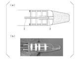
- (A) It is a schematic diagram which shows a mode that the fixing tool and droplet manufacturing device which concern on this invention were accommodated in the tube for droplet collection
- (B) It is a photograph which shows a mode that the fixing tool and droplet manufacturing device which concern on this invention were accommodated in the tube for droplet collection
- 2 is a photograph showing a state of water-in-oil droplets produced in Example 1.
- FIG. (A) It is a photograph which shows the mode of the water-in-oil droplet manufactured in Example 1.
- FIG. (B) It is a photograph which shows the mode of the water-in-oil droplet manufactured in Example 2.
- FIG. (C) It is a photograph which shows the mode of the water-in-oil droplet manufactured in Example 3.
- FIG. (D) is a graph showing the size distribution of water droplets produced in Examples 1 to 3.
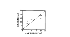
- 6 is a graph showing the relationship between the average value of water droplets produced in Examples 1 to 3 and the inner diameter of the inner tube tip. 6 is a graph showing the evaluation of monodispersity of water droplets produced in Examples 1 to 9.
- FIG. 2 is a photograph showing the state of liposomes produced in Example 11.
- the droplet production device of the present invention is a droplet production device having an outer tube and an inner tube that is disposed inside the outer tube and feeds a droplet raw material, and is downstream in the fluid feeding direction.
- the inner tube discharge port is opened at the tip of the inner tube formed on the outer tube
- the outer tube discharge port is opened at the tip of the outer tube formed on the downstream side in the fluid feeding direction, and the outer tube and the inner tube A gap is formed between the two. In the gap, a fluid that is not mixed with the droplet raw material or difficult to mix is sent.
- the cross-sectional shape of the flow path of the outer tube and the inner tube is not particularly limited, and may be a circle, an ellipse, a polygon, or the like.
- the shape of the inner tube is preferably a shape having no portion in contact with the inner wall of the outer tube so that the gap can be formed around the inner tube without interruption.
- the preferable value of a flow path internal diameter is mentioned later, when the cross-sectional shape of a flow path is not a perfect circle, it can convert into a perfect circle with the substantially same cross-sectional area of a flow path, and can be set as a preferable value of an internal diameter.
- the droplet manufacturing device of the present embodiment is a droplet manufacturing device having an outer tube and an inner tube arranged concentrically, and the inner tube is formed at the tip of the inner tube formed on the downstream side in the fluid feeding direction.
- a discharge port is opened, and an outer tube discharge port is opened at the distal end portion of the outer tube that is also formed on the downstream side in the fluid feeding direction, and a gap is formed between the outer tube and the inner tube.
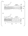
- Fig.1 (a) is an example of embodiment of the droplet manufacturing device based on this invention.
- the droplet manufacturing device 1 of the present embodiment has an outer tube 2 and an inner tube 3 arranged concentrically.
- the cross-sectional shape of the flow path of the outer tube and the inner tube is a perfect circle.
- the inner tube 3 is disposed inside the outer tube 2, and a gap 2 c is formed between the outer tube 2 and the inner tube 3. More specifically, a gap 2 c is formed between the inner wall of the outer tube 2 and the outer wall of the inner tube 3.
- the inner pipe 3 is filled with a fluid F1.
- the gap 2c is filled with a fluid F2. Note that the fluid F1 and the fluid F2 are not components of the droplet manufacturing device of the present embodiment.
- the fluid F1 and the fluid F2 are fed in the axial direction of the outer tube 2 and the inner tube 3.
- the liquid feeding directions of the fluid F1 and the fluid F2 in the outer tube 2 and the inner tube 3 are the same.
- the fluid feeding direction in the droplet manufacturing device 1 of the present embodiment is the direction indicated by the arrow in FIG. 1
- the inner tube discharge port 3b is opened in the inner tube tip 3a
- the outer tube tip An outer tube discharge port 2b is opened in 2a.
- the inner tube discharge port of the droplet manufacturing device of the first embodiment is provided inside the outer tube on the upstream side in the fluid feeding direction from the outer tube discharge port. It is what. Descriptions common to the droplet manufacturing device of the first embodiment are omitted. As shown in FIG.
- the inner tube discharge port 3b is provided inside the outer tube 2 on the upstream side in the liquid feeding direction from the outer tube discharge port 2b.
- the droplet manufacturing device 11 of the present embodiment has the composite tube portion 4 including the outer tube 2 and the inner tube 3 on the upstream side in the liquid feeding direction with respect to the inner tube tip portion 3a.
- a single tube portion 5 made of the outer tube 2 is provided downstream of the distal end portion 3a in the liquid feeding direction.
- FIG. 2 schematically shows how droplets are manufactured using the droplet manufacturing device 11.
- the fluid F2 is introduced into the gap 2c formed between the outer tube 2 and the inner tube 3 in the composite tube portion 4, and the fluid F1 is introduced into the inner tube 3 (FIG. 2 (a)).
- the fluid F1 is a droplet raw material.
- the fluid F2 is introduced into the outer pipe.
- the fluid F1 and the fluid F2 are fed in the direction indicated by the arrow in FIG.
- the fluid F1 and the fluid F2 are fed while maintaining the positional relationship between the concentric outer tube 2 and the inner tube 3, and a laminar flow in which the fluid F2 is the outer layer and the fluid F1 is the inner layer is formed in the single tube portion 5.
- the flow of the fluid F1 which is the inner layer, becomes discontinuous, and droplets of the fluid F1 are formed from the front end (downstream side) of the flow of the fluid F1. It is considered that the flow of the fluid F1 is discontinuous because the flow between the fluid F1 and the fluid F2 in the single pipe portion 5 becomes unstable due to Rayleigh plateau instability.
- the droplet manufacturing device 1 has an outer tube 2 and an inner tube 3, and a gap is formed between the outer tube 2 and the inner tube 3, so that a small amount of liquid droplet material (fluid F ⁇ b> 1)
- a liquid (fluid F2) that is disposed inside the inner tube 3 and that does not or does not easily mix with the liquid droplet material in the gap 2c and only sends the liquid
- droplets of the fluid F1 from a small amount of liquid droplet material can be obtained. It can be manufactured very easily.
- the produced droplets are of high quality with excellent monodispersity.
- the droplet manufacturing device 11 since the single tube portion 5 surrounded by the outer tube 2 is formed, a laminar flow in which the fluid F2 is the outer layer and the fluid F1 is the inner layer is efficiently formed. It is possible to more efficiently produce a droplet having excellent properties.
- the amount of the fluid F1 necessary for manufacturing the droplet of the fluid F1 is only the amount introduced into the inner tube 3, and according to the droplet manufacturing device 1 of the present embodiment, droplets are manufactured from a small amount of droplet raw material. It is possible. In addition, a large number of droplets can be produced in a short time without requiring complicated liquid feeding control.
- the inner diameter a of the inner tube tip 3a of the inner tube 3 constituting the droplet manufacturing device 11 is preferably 0.1 ⁇ m to 500 ⁇ m, more preferably 1 ⁇ m to 100 ⁇ m, and 5 ⁇ m to 30 ⁇ m. Further preferred.
- the manufactured droplet follows the laws of microfluidics, so that it is possible to more easily manufacture a droplet having excellent monodispersity. It becomes. Further, the diameter of the produced droplet and the inner diameter a are likely to show a positive correlation, and the size of the produced droplet can be controlled more easily.
- the ratio between the inner diameter a of the inner tube tip 3a and the inner diameter b of the outer tube tip 2a is not particularly limited as long as a laminar flow in which the fluid F2 is the outer layer and the fluid F1 is the inner layer can be formed.
- the ratio of the inner diameter a to the inner diameter b is preferably 2 to 30 times the inner diameter a, and preferably 3 to 20 times. More preferably, it is 4 to 18 times, more preferably 4.5 to 15 times, and particularly preferably 5 to 10 times.
- a laminar flow in which the fluid F2 is an outer layer and the fluid F1 is an inner layer is formed in the single tube portion 5.
- the shape of the laminar flow is also determined by the ratio between the inner diameter c and the inner diameter a.
- the ratio between the inner diameter c and the inner diameter a is not particularly limited as long as a laminar flow can be formed.
- the inner diameter c of the outer tube at the inner tube tip 3a is the inner tube.
- the inner diameter a of the tip 3a is preferably about 2 to 100 times, more preferably about 3 to 50 times, and further preferably about 5 to 10 times.
- the ratio of the inner diameter c to the inner diameter a is in the above range, a droplet excellent in monodispersity can be obtained more easily.
- the inner diameter c and the inner diameter b indicate the same portion, and therefore the ratio of the inner diameter a to the inner diameter c is This is the same as the ratio between the inner diameter a and the inner diameter b described above.
- the inner diameter b of the outer tube tip 2a is preferably 1 ⁇ m to 1000 ⁇ m, more preferably 10 ⁇ m to 400 ⁇ m, still more preferably 40 ⁇ m to 100 ⁇ m, and particularly preferably 40 ⁇ m to 60 ⁇ m.
- the inner diameter b is 1000 ⁇ m or less, the diameter of the produced droplet and the inner diameter a tend to show a positive correlation.
- the inner diameter b is 60 ⁇ m or less, the fluid discharged from the outer tube distal end portion 2a is unlikely to swell in a bowl shape, so that the diameter of the manufactured droplet and the inner diameter a are more likely to have a positive correlation. For this reason, it is easier to control the size of the droplet.
- Droplets are sequentially formed from the front end (downstream side) of the flow of the fluid F1. Since the droplet manufacturing device 11 has the single tube portion 5, the fluid is efficiently fed by the outer tube 2 constituting the single tube portion 5. Thus, it is preferable that the droplet is formed in the single tube portion 5.
- the distance required for forming the droplet is about 10 times the inner diameter of the droplet. Accordingly, the distance d between the inner tube tip 3a and the outer tube tip 2a is preferably about 2 to 1000 times the inner diameter a of the inner tube tip, more preferably about 5 to 500 times, More preferably, it is about 7 to 300 times.
- the droplet production device of the present invention is preferably a centrifugal droplet production device capable of producing droplets by feeding a droplet raw material by centrifugal force.
- a centrifugal droplet production device has a structure suitable for producing droplets by centrifugal force using a centrifugal separator or the like.
- a centrifugal force capable of producing droplets may be applied. It is strong enough not to break.
- the length of the droplet production device 11 is preferably in the range of 0.1 to 30 cm, preferably 0.5 to 15 cm. The range is more preferable, and the range of 1 to 5 cm is more preferable.
- the constituent materials of the outer tube 2 and the inner tube 3 are not particularly limited, and for example, materials such as resin, metal, glass and the like can be used. Especially, it is preferable that glass is used as a constituent material of the outer tube 2 and the inner tube 3.
- the glass tube can be easily produced by heating and stretching a commercially available glass tube. If the glass tube is cut at a portion having a desired diameter, the outer tube 2 having the desired diameter can be easily obtained. And the inner pipe
- the droplet manufacturing method of the present invention is a droplet manufacturing method using the droplet manufacturing device of the present invention, and the second fluid is introduced into a gap formed between the outer tube and the inner tube.
- the first fluid and the second fluid are simultaneously fed to cause the second fluid to flow into the outer layer.
- the fluid in which the first fluid is an inner layer is formed.
- a droplet manufacturing method using the droplet manufacturing device 11 of the second embodiment shown in the above ⁇ Droplet manufacturing device >>.
- the first fluid corresponds to the fluid F1
- the second fluid corresponds to the fluid F2.
- the method for producing droplets using the droplet production device 11 is the same as that described above with reference to FIG.
- a fluid in which the second fluid is an outer layer and the first fluid is an inner layer is formed between the inner tube tip and the outer tube tip.
- the liquid transfer operation required for manufacturing a droplet having excellent monodispersibility is sufficient in at least one direction and only once, and a complicated transfer operation is required. Liquid control is not required and high droplet productivity can be realized.
- the means for feeding the liquid is not particularly limited, and can be performed by a conventional method such as using a pump, but is preferably performed using centrifugal force. Liquid feeding using centrifugal force can be performed using a centrifuge or the like. A desktop small centrifuge is preferred as the centrifuge.
- the method for producing droplets of the present invention is also excellent in that liquid can be easily fed using a desktop small centrifuge. When a conventional method for producing liquid droplets using a microchannel is used to send a liquid by a syringe pump, the liquid of the liquid droplet material needs to be filled in the syringe or the connection between the syringe and the channel. It was.
- an extra droplet raw material that becomes a dead volume is required in the syringe or in the connection portion between the syringe and the flow path.
- mL of drop source liquid was required.
- the droplet material necessary for producing the droplet of the fluid F1 is not necessary. Since the amount is only introduced into the inner tube 3, for example, 10,000 droplets having a diameter of 10 ⁇ m can be produced from a 0.1 ⁇ L droplet raw material.
- liquid feeding by a centrifuge does not require complicated liquid feeding control, liquid feeding operation can be performed very easily as compared with liquid feeding using a pump.
- the combination of the first fluid and the second fluid is a combination of two liquid phase separation systems or a mixture of two liquids.
- a preferable combination of the fluid F1 and the fluid F2 includes a combination of oil and water.
- the fluid F1 may be a combination of water and the fluid F2 may be a combination of oil (water droplets in oil), or the opposite fluid F1 may be a combination of oil and the fluid F2 may be a combination of water (oil-in-water droplets).
- the oil include mineral oil, vegetable oil such as olive oil, silicone oil, decane and the like.
- the water may be in the form of an aqueous solution, and examples thereof include solutions derived from biological samples such as buffers and cell extracts.
- the droplet interface may be compartmentalized by amphiphilic molecules. Since the interface is partitioned by the amphiphilic molecules, the possibility that the droplets are fused is reduced.
- amphiphilic molecules include surfactants and lipids.
- the surfactant include Span 80, Tween 80, Tween 20, Triton X-100, sodium dodecyl sulfate (SDS) and the like.
- lipids include dioleoylphosphatidylcholine (DOPC), dipalmitoyl phosphatidylcholine (DPPC), cholesterol, sphingomyelin, glycolipid ganglioside and the like.
- Each droplet can be used as a small test tube. By containing a reactant in the droplet, a large number of chemical reactions can be caused independently in each droplet. Since the droplet produced by the method for producing a droplet of the present invention is excellent in monodispersity, the measurement result can be used as the measurement result of a homogeneous multi-sample. This is useful for obtaining an average value of reaction results. In addition, since different reaction conditions, samples, and the like can be included for each droplet, multiple specimens can be screened at once or various conditions can be tried at once. Examples of reactions that can be performed in the droplet include chemical synthesis, genetic analysis, PCR, protein crystallization, enzyme activity measurement and the like.
- ⁇ Method for producing artificial cell membrane vesicle (liposome)> it is possible to produce a large amount of minute droplets having a diameter of about 0.1 ⁇ m to 500 ⁇ m, for example.
- the droplet size of 0.1 ⁇ m to 500 ⁇ m in diameter includes a general cell size of about 5 ⁇ m to 30 ⁇ m in diameter, so that an artificial cell membrane vesicle (liposome) having a structure imitating a cell can be produced. .
- liposomes are included in droplets.
- FIG. 4 schematically shows an example of how artificial cell membrane vesicles (liposomes) using the droplet manufacturing device 11 are manufactured.
- FIG. 4 schematically shows an example of how artificial cell membrane vesicles (liposomes) using the droplet manufacturing device 11 are manufactured.
- Fluid F2 contains dioleoylphosphatidylcholine (DOPC) as an amphiphilic molecule.
- DOPC dioleoylphosphatidylcholine
- the outer tube tip 2a of the droplet manufacturing device 11 is disposed so as to be immersed in the same mineral oil as the fluid F2. Further, water or a buffer solution is arranged on the downstream side in the liquid feeding direction. DOPC is arranged as an amphiphilic molecule at the interface between water or buffer and mineral oil.
- the droplet manufactured by the droplet manufacturing device 11 is discharged into the mineral oil from the outer tube tip 2a.
- the droplets released at this time have a lipid monolayer.
- the liquid droplet travels straight in the liquid feeding direction, comes into contact with the DOPC disposed at the interface between the mineral oil and water or the buffer solution, and reaches the water or the buffer solution while being wrapped in the DOPC.
- the droplet has a lipid bilayer membrane.
- artificial cell membrane vesicles liposomes
- an artificial cell that is functionally similar to a cell can be obtained.
- various metabolic reactions that normally occur inside and outside the cell can occur inside the droplet.
- the outer layer and the inner layer of the lipid bilayer membrane can be made asymmetric.
- the fixture of the present invention is a fixture used to arrange the inner tube constituting the droplet manufacturing device of the present invention inside the outer tube, and is an outer tube fixing for fixing the outer tube.
- FIG. 5 is an example of an embodiment of the fixture 6 according to the present invention.
- the outer tube fixing member 7 and the inner tube fixing member 8 are plate-like members having a hole in the center, and the outer tube fixing member 7 and the inner tube fixing member 8 are connected by a connecting member 9.
- the connecting member 9 is a screw that rotatably connects the outer tube fixing member 7 and the inner tube fixing member 8.
- the fixture 6 is provided with support bodies 10 and 10 'which are plate-like members having a hole in the central portion in order to support the outer tube and the inner tube and to maintain the concentric arrangement more effectively. .
- FIG. 6 an example of the procedure which arrange
- the inner tube fixing member 8 and the support 10 ′ are rotated, and the centers of the holes of the outer tube fixing member 7 and the support 10 and the centers of the holes of the inner tube fixing member 8 and the support 10 ′
- the outer tube 2 is inserted into each hole of the outer tube fixing member 7 and the support 10 (FIG. 6B).
- the outer tube 2 is fitted by passing through the hole 7 a provided in the outer tube fixing member 7. Fixed.
- the inner tube fixing member 8 and the support 10 ′ are rotated, and the centers of the holes of the outer tube fixing member 7 and the support 10 and the centers of the holes of the inner tube fixing member 8 and the support 10 ′ And the inner tube 3 is inserted into each hole of the inner tube fixing member 8 and the support 10 '(FIG. 6C).
- the inner tube 3 is fitted by passing the inner tube 3 through the hole 8a provided in the inner tube fixing member 8, The inner tube 3 is fixed.
- the outer tube 2 and the inner tube 3 can be arranged concentrically.
- the outer tube fixing member 7, the support 10, the inner tube fixing member 8 and the support 10 ′ are connected by a connecting member 9 that is a screw. Therefore, it is possible to adjust the distance between members by rotating each member. Even if the outer tube 2 and the inner tube 3 are not arranged concentrically because the distance between the outer tube fixing member 7 and the inner tube fixing member 8 is too large, the outer tube fixing member 7 and the inner tube fixing member 8 The distance can be reduced and adjusted so that the inner tube 3 is concentrically arranged in the outer tube 2.
- the liquid droplets manufactured by the liquid droplet manufacturing device may be stored in a container disposed on the downstream side in the liquid feed direction of the liquid droplet raw material.
- the fixture 6 may be used to attach the inner tube and the outer tube to the container, in addition to being used to place the inner tube inside the outer tube.
- a part or all of the fixture 6 is inserted into the container, and the surfaces of the constituent members of the fixture 6 such as the outer tube fixing member 7, the inner tube fixing member 8, the support 10 and the support 10 ', and the container
- the inner tube and the outer tube can be attached to the container by contacting the inner wall surface (see also FIG. 7 described later).
- the droplet production kit of the present invention includes an outer tube and an inner tube, and the droplet production device of the present invention is formed by arranging the inner tube inside the outer tube.
- the droplet manufacturing device the above-described droplet manufacturing device 1 and droplet manufacturing device 11 are typified.
- the droplet manufacturing kit of the present invention may further include a fixing device of the present invention, reagents such as a droplet raw material, amphiphilic molecules and the like, a container for storing the manufactured droplets, and the like.
- the fixing tool is represented by the fixing tool 6 described above.
- the inner tube 3 constituting the droplet manufacturing device has a plurality of types of inner tubes having different inner diameters at the inner tube tip 3a for the purpose of manufacturing droplets of a plurality of types.
- a tube 3 may be provided. According to the droplet manufacturing kit including the inner tube 3 in which the inner tube tip 3a has different inner diameters, it is possible to easily manufacture droplets of a plurality of sizes simply by replacing the inner tube 3.
- Example 1 [Preparation of droplet production device with inner and outer tubes fixed using fixtures] (Inner tube / outer tube) Using a puller (manufacturer: Narishige, model number: PC-10), pull out a commercially available glass tube (manufacturer: Narishige, model number: G-1, manufacturer: World Precision Instruments, model number: 1B200-6). An outer tube 2 and an inner tube 3 having a shape were produced.
- Polyacetal resin is processed to produce four plates with a diameter of 0.9 cm, a thickness of 0.2 cm, and a hole with a diameter of 0.2 cm in the center, each of which is an outer tube fixing member 7, a support 10, and an inner tube
- the fixing member 8 and the support 10 ′ were used.
- two screw holes for penetrating two screws (standard: M2 ⁇ 15) were provided at the same position at the end of each plate. The first screw was passed through the outer tube fixing member 7, the support 10, the inner tube fixing member 8, and the support 10 'in the order shown in FIGS.
- the distance d between the inner tube tip 3a and the outer tube tip 2a was 2000 ⁇ m, and the inner diameter c of the outer tube at the inner tube tip 3a was 115 ⁇ m.
- the second screw was passed through the outer tube fixing member 7, the support 10, the inner tube fixing member 8, and the support 10 'to fix them.
- Example 2 In the production of the droplet production device of Example 1, a droplet production device was produced in the same manner as in Example 1 except that the inner diameter a of the inner tube tip 3a was changed to 5 ⁇ m, and a droplet was produced. [Confirmation of droplets] An image of water droplets produced in Example 2 is shown in FIG.
- Example 3 In the production of the droplet production device of Example 1, a droplet production device was produced in the same manner as in Example 1 except that the inner diameter a of the inner tube tip 3a was 20 ⁇ m, and a droplet was produced. [Confirmation of droplets] An image of water droplets produced in Example 3 is shown in FIG.
- the droplets produced from the droplet production devices of Examples 1, 2, 4 to 9 have a monodispersity control rate of 80% or more. According to these droplet production devices, the monodispersity is extremely high. It has been shown that excellent droplets can be produced.
- ⁇ Example 10 Synthesis of fluorescent protein> Protein synthesis was performed in droplets produced using a droplet production device. First, a buffer solution containing a protein expression system (green fluorescent protein (GFP) template DNA, amino acids, various factors necessary for protein synthesis) was introduced into the inner tube to produce droplets. The produced droplet was collected in a 1.5 mL tube. The 1.5 mL tube was then incubated at 37 ° C. As a result, template DNA information is transcribed, RNA is synthesized, and RNA information is translated to synthesize a protein. The state of the droplet before and after 37 ° C. incubation is shown in FIG. Since the expressed protein is GFP this time, green fluorescence was observed only in the droplet. It was shown that protein synthesis is possible in the droplets produced by the droplet production device according to the present invention.
- a protein expression system green fluorescent protein (GFP) template DNA, amino acids, various factors necessary for protein synthesis
- Example 11 Production of liposome>
- L- ⁇ -phosphatidylcholine Egg PC (100 %)
- mineral oil containing L- ⁇ -phosphatidylcholine Egg PC (100%)
- Liposomes were produced in the same manner as in Example 1 except that water was introduced.
- EggPC is uniformly arranged at the interface between mineral oil and water.
- FIG. 11 An image of the liposome produced in Example 11 is shown in FIG. According to this example, it was shown that liposomes can be produced by the droplet production device shown in Example 1 above.
- the present invention can be widely used in chemistry-related fields, physics-related fields, biological fields, and the like, and can also be used for chemical synthesis, gene analysis, and the like. Further, as shown in the examples, the present invention can be used for protein synthesis in droplets and for the production of artificial cell membrane vesicles (liposomes), and thus is particularly suitable in the fields related to biology and medicine. Is available.
Landscapes
- Chemical & Material Sciences (AREA)
- Health & Medical Sciences (AREA)
- Dispersion Chemistry (AREA)
- Chemical Kinetics & Catalysis (AREA)
- Organic Chemistry (AREA)
- Analytical Chemistry (AREA)
- General Health & Medical Sciences (AREA)
- Hematology (AREA)
- Clinical Laboratory Science (AREA)
- Manufacturing Of Micro-Capsules (AREA)
- Physical Or Chemical Processes And Apparatus (AREA)
- Immobilizing And Processing Of Enzymes And Microorganisms (AREA)
Abstract
Description
通常、流路への送液はシリンジポンプが用いられる。しかし、シリンジポンプを用いた場合では、シリンジ内やシリンジと流路との接続部に液滴原料の液が充填される必要があるため、製造した液滴分の液滴原料よりも多くの液滴原料を用意する必要がある。液滴原料としたいサンプルが希少である場合には、このような原料のロスを少なくすることが強く求められる。
また、単分散性に優れる高品質な液滴を製造しようとするとシリンジポンプの動作を正確に行わなければならず、その調整が煩雑である。さらには、正確な送液が求められることにより液滴の生産スピードが低下してしまうという欠点もある。
すなわち、本発明は、下記の特徴を有する液滴製造デバイス、液滴の製造方法、固定具及び液滴製造キットを提供する。
流体の送液方向で下流側に形成された内管先端部に内管吐出口が開口し、同じく流体の送液方向で下流側に形成された外管先端部に外管吐出口が開口し、
前記外管と前記内管との間には間隙が形成されることを特徴とする液滴製造デバイス。
(2)前記内管吐出口は前記外管吐出口よりも流体の送液方向で上流側の外管内部に設けられた前記(1)に記載の液滴製造デバイス。
(3)前記外管先端部の内径bが、前記内管先端部の内径aの2~30倍である前記(1)又は(2)に記載の液滴製造デバイス。
(4)前記内管先端部の内径aが0.1μm~500μmである前記(1)~(3)のいずれか一つに記載の液滴製造デバイス。
(5)前記内管先端部における前記外管の内径cが、前記内管先端部の内径aの2~100倍である前記(1)~(4)のいずれか一つに記載の液滴製造デバイス。
(6)前記外管先端部の内径bが1μm~1000μmである前記(1)~(5)のいずれか一つに記載の液滴製造デバイス。
(7)前記内管先端部と前記前記外管先端部との距離dが、前記内管先端部の内径aの2~1000倍である前記(2)~(6)のいずれか一つに記載の液滴製造デバイス。
前記外管と前記内管との間に形成された間隙に第2の流体が導入され、前記内管内部に第1の流体が導入された状態にある液滴製造デバイスに対して、
前記第1の流体及び前記第2の流体を同時に送液させることにより、前記第2の流体が外層であり前記第1の流体が内層である流体を形成させて液滴を形成させる液滴の製造方法。
(9)前記送液が遠心力を用いて行われる前記(8)に記載の液滴の製造方法。
(10)前記液滴がレイリー・プラトー不安定性により形成される前記(8)又は(9)に記載の液滴の製造方法。
(11)前記第1の流体が生体分子を含有する前記(8)~(10)のいずれか一つに記載の液滴の製造方法。
(12)前記(8)~(11)のいずれか一つに記載の液滴の製造方法を用いるリポソームの製造方法であって、
液の界面に配置された両親媒性分子と接触させ、両親媒性分子を含有する膜を前記液滴表面に多重に形成させるリポソームの製造方法。
前記外管を固定するための外管固定部材と、前記内管を固定するための内管固定部材とを有する固定具。
(14)前記外管固定部材及び前記内管固定部材は中央部に孔を有する板状の部材であり、
前記外管固定部材及び前記内管固定部材は連結部材により連結され、
前記外管固定部材が有する前記孔及び内管固定部材が有する前記孔の夫々に、前記外管及び前記内管が嵌め込まれることで、前記内管が前記外管内部に配置される前記(13)に記載の固定具。
(15)前記連結部材は、前記外管固定部材と前記内管固定部材とを回転自在に連結するネジである前記(13)又は(14)に記載の固定具。
(16)外管と、内管と、を備える液滴製造キットであって、
該内管を該外管内部に配置することにより、前記(1)~(7)のいずれか一つに記載の液滴製造デバイスを形成する液滴製造キット。
(17)前記(13)~(15)のいずれか一つに記載の固定具をさらに備える前記(16)に記載の液滴製造キット。
本発明の液滴製造デバイスは、外管と、該外管の内部に配置され液滴原料を送液する内管と、を有する液滴製造デバイスであって、流体の送液方向で下流側に形成された内管先端部に内管吐出口が開口し、同じく流体の送液方向で下流側に形成された外管先端部に外管吐出口が開口し、前記外管と前記内管との間には間隙が形成される。間隙では液滴原料とは混じり合わない又は混じり合い難い流体が送液される。
なお、好ましい流路内径の値について後述するが、流路の断面形状が真円でない場合、流路の断面積がほぼ同一の真円として換算し、好ましい内径の値とすることができる。
本実施形態の液滴製造デバイスは、同心円状に配置された外管及び内管を有する液滴製造デバイスであって、流体の送液方向で下流側に形成された内管先端部に内管吐出口が開口し、同じく流体の送液方向で下流側に形成された外管先端部に外管吐出口が開口し、前記外管と前記内管との間には間隙が形成されるものである。
以下、本発明に係る液滴製造デバイスの実施形態の一例を、図面を参照して説明する。
図1(a)は、本発明に係る液滴製造デバイスの実施形態の一例である。本実施形態の液滴製造デバイス1は、同心円状に配置された外管2及び内管3を有している。外管及び内管の流路の断面形状は真円である。図1に示すように、内管3は外管2の内部に配置され、外管2と内管3との間には間隙2cが形成されている。より詳しくは、外管2の内壁と内管3の外壁との間には間隙2cが形成されている。
内管3の内部には流体F1が充填されている。間隙2cには流体F2が充填されている。なお、流体F1及び流体F2は本実施形態の液滴製造デバイスの構成要素ではない。
前記流体F1及び流体F2は、外管2及び内管3の軸方向に送液される。外管2及び内管3における流体F1及び流体F2の送液方向は互いに同一である。本実施形態の液滴製造デバイス1における流体の送液方向を、図1中の矢印で示される方向としたとき、内管先端部3aには内管吐出口3bが開口し、外管先端部2aには外管吐出口2bが開口している。
<第二実施形態>
本実施形態の液滴製造デバイス11は、前記第一実施形態の液滴製造デバイスの内管吐出口が前記外管吐出口よりも流体の送液方向で上流側の外管内部に設けられているものである。第一実施形態の液滴製造デバイスと共通する点について、説明を省略する。
図1(b)に示すように、内管吐出口3bは、外管吐出口2bよりも当該送液方向の上流側の外管2内部に設けられている。このように、本実施形態の液滴製造デバイス11は、内管先端部3aよりも送液方向上流側では、外管2と内管3からなる複合管部4を有しており、内管先端部3aよりも送液方向下流側では、外管2からなる単管部5を有している。
流体F1の流れが不連続となるのは、単管部5における流体F1及び流体F2間の流れがレイリー・プラトー不安定性により不安定となることによると考えられる。
次に、単分散性に優れる液滴をより容易に製造可能とするとの観点から、本発明に係る液滴製造デバイスの好ましい形状について、図3を参照して説明する。
液滴製造デバイス11を構成する内管3の内管先端部3aの内径aは、0.1μm~500μmであることが好ましく、1μm~100μmであることがより好ましく、5μm~30μmであることがさらに好ましい。内管先端部3aの内径aが上記範囲にある液滴製造デバイス11では、製造される液滴はマイクロ流体力学の法則に従うため、単分散性に優れる液滴をより容易に製造することが可能となる。また、製造される液滴の直径と内径aとが正の相関を示し易く、製造される液滴のサイズ制御をより容易に行うことができる。
なお、上述の液滴製造デバイス1のように内管先端部3aが外管先端部2aと一致する場合は、内径cと内径bは同一部分を指すので、内径aと内径cの比は、上述した内径aと内径bとの比と同様である。
また、遠心分離機を用いた遠心力による送液を容易とするという観点から、液滴製造デバイス11の長さは、0.1~30cmの範囲であることが好ましく、0.5~15cmの範囲であることがより好ましく、1~5cmの範囲であることがさらに好ましい。
本発明の液滴の製造方法は、本発明の液滴製造デバイスを用いる液滴の製造方法であって、前記外管と前記内管との間に形成された間隙に第2の流体が導入され、前記内管内部に第1の流体が導入された状態にある液滴製造デバイスにおいて、前記第1の流体及び前記第2の流体を同時に送液させることにより、前記第2の流体が外層であり前記第1の流体が内層である流体を形成させるものである。
一例としては、上述の≪液滴製造デバイス≫で示した第二実施形態の液滴製造デバイス11を用いる液滴の製造方法である。第1の流体が流体F1に相当し、第2の流体が流体F2に相当する。液滴製造デバイス11を用いた液滴の製造方法については、上述の≪液滴製造デバイス≫の説明において先に図2を参照して説明したものと重複するため、説明を省略する。なお、液滴製造デバイス11を用いた場合、前記第2の流体が外層であり前記第1の流体が内層である流体を、前記内管先端部と前記前記外管先端部との間に形成させるので、送液が効率的となり、単分散性に優れる液滴をより効率的に製造することができる。
本発明の液滴の製造方法によれば、例えば、直径0.1μm~500μm程度の微小液滴を多量に製造することが可能である。この直径0.1μm~500μmの液滴サイズは、一般的な細胞のサイズである直径5μm~30μm程度を包含するので、細胞を模した構造の人工細胞膜小胞(リポソーム)を製造することができる。なお、本発明において、リポソームは液滴に包含されるものとする。
以下、図4に、液滴製造デバイス11を用いた人工細胞膜小胞(リポソーム)が製造される様子の一例を模式的に示す。図4は液滴製造デバイス11により液滴が製造される過程を示している。内管3には流体F1として水又は緩衝液が導入されている。間隙2cには流体F2としてミネラルオイルが導入されている。流体F2には両親媒性分子としてジオレオイルフォスファチヂルコリン(DOPC)が含有されている。液滴製造デバイス11の外管先端部2aは流体F2と同じミネラルオイルに没するように配置されている。さらに送液方向の下流側では、今度は水又は緩衝液が配置されている。水又は緩衝液とミネラルオイルの界面には両親媒性分子としてDOPCが配置されている。
まず、液滴製造デバイス11により製造された液滴が外管先端部2aからミネラルオイル内へと放出される。この時放出された液滴は脂質の一重膜を有している。このまま該液滴は送液方向を直進しミネラルオイルと水又は緩衝液の界面に配置されたDOPCに接触し、DOPCに包まれつつ水又は緩衝液内へと到達する。この時、液滴は脂質二重膜を有している。このようにして、細胞と同様に脂質二重膜を有する人工細胞膜小胞(リポソーム)を得ることができる。
さらに、流体F1内に予めタンパク質、DNA、RNA等の生体分子及び/又は生体物質を含有させることで、機能的にも細胞に類似した人工細胞とすることができる。これらの生体分子を用いて、細胞内及び細胞外で通常生じる種々の代謝の反応を、液滴内部にて生じさせることが可能である。
また、流体F2内に混合している脂質と下流側のミネラルオイル内に混合している脂質を異なる種類のものにすることで、脂質二重膜の外層と内層を非対称にすることができる。
本発明の固定具は、本発明の液滴製造デバイスを構成する前記内管を、前記外管内部に配置するために用いられる固定具であって、前記外管を固定するための外管固定部材と、前記内管を固定するための内管固定部材とを有する。
図5は本発明に係る固定具6の実施形態の一例である。
外管固定部材7及び内管固定部材8は中央部に孔を有する板状の部材であり、外管固定部材7及び内管固定部材8は連結部材9により連結されている。連結部材9は、外管固定部材7と内管固定部材8とを回転自在に連結するネジである。さらに固定具6には、外管及び内管を支えてより効果的に同心円状の配置を保つため、中央部に孔を有する板状の部材である支持体10,10’が備えられている。
まず、内管固定部材8及び支持体10’を回転させ、外管固定部材7及び支持体10の有する各孔の中心と、内管固定部材8及び支持体10’の有する各孔の中心とをずらし、外管固定部材7及び支持体10の有する各孔に外管2を挿入する(図6(b))。ここで外管2は流体の送液方向で上流側ほど外径が大きくされているので、外管固定部材7に設けられた孔7aに通すことで外管2が嵌め込まれ、外管2が固定される。
次いで、内管固定部材8及び支持体10’を回転させ、外管固定部材7及び支持体10の有する各孔の中心と、内管固定部材8及び支持体10’の有する各孔の中心とを一致させ、内管固定部材8及び支持体10’の有する各孔に内管3を挿入する(図6(c))。ここで内管3も流体の送液方向で上流側ほど外径が大きくされているので、内管3を内管固定部材8に設けられた孔8aに通すことで内管3が嵌め込まれ、内管3が固定される。このようにして、外管2及び内管3を同心円状に配置することができる。
固定具6では、外管固定部材7、支持体10、内管固定部材8及び支持体10’がネジである連結部材9によって連結されている。そのため、各部材を回転させて部材同士の距離を調節することが可能である。仮に外管固定部材7と内管固定部材8との距離が大きすぎるために外管2と内管3とが同心円状に配置されない場合でも、外管固定部材7と内管固定部材8との距離を小さくして、外管2内に内管3が同心円状に配置されるよう調節することができる。
本発明の液滴製造キットは外管と内管とを備え、内管を外管内部に配置することにより、本発明の液滴製造デバイスを形成する。液滴製造デバイスとしては、上述した液滴製造デバイス1及び液滴製造デバイス11に代表される。
また、本発明の液滴製造キットは、本発明の固定具、液滴原料、両親媒性分子等の試薬類、製造された液滴を溜めるための容器等をさらに備えてもよい。固定具としては、上述した固定具6に代表される。
本発明の液滴製造キットでは、複数種類のサイズの液滴を製造可能とする目的で、液滴製造デバイスを構成する内管3が、内管先端部3aの内径が夫々異なる複数種類の内管3を備えていてもよい。内管先端部3aの内径が異なる内管3を備える液滴製造キットによれば、内管3を取り換えるだけで簡便に複数サイズの液滴を製造可能である。
[固定具を使用して内管及び外管が固定された液滴製造デバイスの作製]
(内管・外管)
プーラー(製造元:ナリシゲ、型番:PC-10)を使用して、市販のガラス管(製造元:ナリシゲ、型番:G-1, 製造元:World Precision Instruments、型番:1B200―6)を引きのばし、以下の形状を有する外管2及び内管3を作製した。
内管先端部3aの内径a:10μm
外管先端部2aの内径b:60μm
(固定具)
ポリアセタール樹脂を加工し、直径0.9cm、厚み0.2cmで中心部に直径0.2cmの孔が設けられた板を4枚作製し、それぞれを外管固定部材7、支持体10、内管固定部材8及び支持体10’とした。さらに2本のネジ(規格:M2×15)を貫通させるための2か所ネジ穴を、各板の端部にそれぞれ同位置に設けた。外管固定部材7、支持体10、内管固定部材8及び支持体10’に図5及び図6に示される順で1本目のネジを通した。
外管2内部に、Span80を2%(w/w)含有するヘキサデカンを9μL封入した。
内管先端部3aを、水に浸し、毛細管現象により内管3内部に0.1μLの水を吸い上げた。なお、内管3内部には10μL程度の水を封入可能である。
(内管及び外管の固定)
図6に示す手順で、固定具6を用いて外管2と内管3とを同心円状に配置した。これにより外管2と内管3との間に形成された間隙2cにSpan80を含有したヘキサデカンが、内管3内部に水がそれぞれ導入された状態となった。内管先端部3aと前記外管先端部2aとの距離dは2000μmであり、内管先端部3aにおける外管の内径cは115μmであった。2本目のネジを外管固定部材7、支持体10、内管固定部材8及び支持体10’に通してこれらを固定した。
市販の1.5mLチューブ(製造元:日京テクノス(株)、型番:MP-150HC)に100μLのヘキサデカンを注ぎ、外管2及び内管3を固定した固定具6をチューブへと収納した(図7(a),(b))。このとき外管先端部はチューブ底に溜められたヘキサデカンの液中に浸っていた。
チューブを卓上小型遠心機(製造元:(株)ハイテック、型番:ATT-101)にセットし、1200G(使用した卓上小型遠心機の最大出力)の遠心力で3秒間遠心し、ヘキサデカン及び水を同時に送液し、レイリー・プラトー不安定性により水滴を製造した。製造された水滴はチューブ底に溜められたヘキサデカン中に放出された。
実施例1において製造された水滴の画像を図8及び図9(a)に示す。3秒間の送液操作で約5万個の液滴を製造することができた。
実施例1の液滴製造デバイスの作製において、内管先端部3aの内径aを5μmにした以外は実施例1と同様にして液滴製造デバイスの作製を行い、液滴を製造した。
[液滴の確認]
実施例2において製造された水滴の画像を図9(b)に示す。
実施例1の液滴製造デバイスの作製において、内管先端部3aの内径aを20μmにした以外は実施例1と同様にして液滴製造デバイスの作製を行い、液滴を製造した。
[液滴の確認]
実施例3において製造された水滴の画像を図9(c)に示す。
実施例1~3で製造された水滴のサイズを計測した結果を図9(d)のグラフに示す。図9(d)のグラフから単分散性に優れる液滴を、短時間で大量に製造できたことがわかる。
a = 5 μmで、x = 8.0±3.0 μm
a = 10 μmで、x = 13.0±3.3 μm
a = 20 μmで、x = 18.5±4.2 μm
この値をグラフにしたものを図10に示す。内管先端部の内径と油中水滴の直径は、ほぼ比例関係にあることがわかる。このことから、内管の先端部の内径(a)を変更するだけで、水滴の直径を制御可能であることが示された。
実施例1~3と同様にして、内径aがそれぞれ5μm、10μm、20μmである内管を製造し、内径bがそれぞれ40μm、60μm、80μm、100μmである外管を製造した。これらの外管と内管を組みわせ、以下の形状を有する液滴製造デバイスを製造した。

結果を図11に示す。実施例1~9の液滴製造デバイスにより製造された液滴は、単分散性制御率60%以上であり、これらの液滴製造デバイスによれば、単分散性に優れた液滴を製造可能であることが示された。特に、実施例1、2、4~9の液滴製造デバイスより製造された液滴は、単分散性制御率80%以上であり、これらの液滴製造デバイスによれば、単分散性に極めて優れた液滴を製造可能であることが示された。
液滴製造デバイスを用いて製造した液滴内で、タンパク質合成を行った。まず、内管内部にタンパク質発現システム(緑色蛍光タンパク質(GFP)の鋳型DNA、アミノ酸、タンパク質合成に必要な各種因子)を含む緩衝液を導入し、液滴を製造した。製造された液滴は1.5mLチューブに溜められた。
次いで、当該1.5mLチューブを37℃でインキュベーションした。これにより鋳型DNAの情報が転写され、RNAが合成され、さらにはRNAの情報が翻訳されて、タンパク質が合成される。37℃インキュベーション前と、37℃インキュベーション後の液滴の様子を図12に示す。今回、発現させたタンパク質はGFPなので、液滴内でのみ、緑色の蛍光が観察された。本発明に係る液滴製造デバイスにより製造された液滴内で、タンパク質の合成が可能であることが示された。
上記実施例1に示す液滴製造デバイス、及びそれを用いた液滴の製造において、間隙2Cに導入したSpan80を含有したヘキサデカンに代えて、終濃度5mMでL-α-phosphatidylcholine(Egg PC(100%))を含有したミネラルオイルを導入したこと、並びに、1.5mLチューブに注いだヘキサデカンに代えて、終濃度5mMでL-α-phosphatidylcholine(Egg PC(100%))を含有したミネラルオイル及び水を導入したこと以外は、実施例1と同様にして、リポソームの製造を行った。上記1.5mLチューブ内では、ミネラルオイルと水との界面にEggPCが一様に配置される。
内管先端部の内径(a)とリポソームの直径サイズ(x)については、以下の値であった。
a = 10 μmで、x = 10.0±4.0μm
6…固定具、7…外管固定部材、8…内管固定部材、9…連結部材、10,10’…支持体、F1,F2…流体
Claims (17)
- 外管と、該外管の内部に配置され、液滴原料を送液する内管と、を備える液滴製造デバイスであって、
流体の送液方向で下流側に形成された内管先端部に内管吐出口が開口し、同じく流体の送液方向で下流側に形成された外管先端部に外管吐出口が開口し、
前記外管と前記内管との間には間隙が形成されることを特徴とする液滴製造デバイス。 - 前記内管吐出口は前記外管吐出口よりも流体の送液方向で上流側の外管内部に設けられた請求項1に記載の液滴製造デバイス。
- 前記外管先端部の内径bが、前記内管先端部の内径aの2~30倍である請求項1又は2に記載の液滴製造デバイス。
- 前記内管先端部の内径aが0.1μm~500μmである請求項1~3のいずれか一項に記載の液滴製造デバイス。
- 前記内管先端部における前記外管の内径cが、前記内管先端部の内径aの2~100倍である請求項1~4のいずれか一項に記載の液滴製造デバイス。
- 前記外管先端部の内径bが1μm~1000μmである請求項1~5のいずれか一項に記載の液滴製造デバイス。
- 前記内管先端部と前記前記外管先端部との距離dが、前記内管先端部の内径aの2~1000倍である請求項2~6のいずれか一項に記載の液滴製造デバイス。
- 請求項1~7のいずれか一項に記載の液滴製造デバイスを用いる液滴の製造方法であって、
前記外管と前記内管との間に形成された間隙に第2の流体が導入され、前記内管内部に第1の流体が導入された状態にある液滴製造デバイスに対して、
前記第1の流体及び前記第2の流体を同時に送液させることにより、前記第2の流体が外層であり前記第1の流体が内層である流体を形成させて液滴を形成させる液滴の製造方法。 - 前記送液が遠心力を用いて行われる請求項8に記載の液滴の製造方法。
- 前記液滴がレイリー・プラトー不安定性により形成される請求項8又は9に記載の液滴の製造方法。
- 前記第1の流体が生体分子を含有する請求項8~10のいずれか一項に記載の液滴の製造方法。
- 請求項8~11のいずれか一項に記載の液滴の製造方法を用いるリポソームの製造方法であって、
液の界面に配置された両親媒性分子と接触させ、両親媒性分子を含有する膜を前記液滴表面に多重に形成させるリポソームの製造方法。 - 請求項1~7のいずれか一項に記載の液滴製造デバイスを構成する前記内管を、前記外管内部に配置するために用いられる固定具であって、
前記外管を固定するための外管固定部材と、前記内管を固定するための内管固定部材とを有する固定具。 - 前記外管固定部材及び前記内管固定部材は中央部に孔を有する板状の部材であり、
前記外管固定部材及び前記内管固定部材は連結部材により連結され、
前記外管固定部材が有する前記孔及び前記内管固定部材が有する前記孔の夫々に、前記外管及び前記内管が嵌め込まれることで、前記内管が前記外管内部に配置される請求項13に記載の固定具。 - 前記連結部材は、前記外管固定部材と前記内管固定部材とを回転自在に連結するネジである請求項14に記載の固定具。
- 外管と、内管と、を備える液滴製造キットであって、
該内管を該外管内部に配置することにより、請求項1~7のいずれか一項に記載の液滴製造デバイスを形成する液滴製造キット。 - 請求項13~15のいずれか一項に記載の固定具をさらに備える請求項16に記載の液滴製造キット。
Priority Applications (5)
| Application Number | Priority Date | Filing Date | Title |
|---|---|---|---|
| EP15762221.8A EP3117897A4 (en) | 2014-03-11 | 2015-03-11 | Droplet producing device, droplet producing method, liposome producing method, fixture, and droplet producing kit |
| CN201580012717.0A CN106255548A (zh) | 2014-03-11 | 2015-03-11 | 液滴制造器件、液滴的制造方法、脂质体的制造方法、固定工具及液滴制造工具盒 |
| SG11201607493QA SG11201607493QA (en) | 2014-03-11 | 2015-03-11 | Droplet producing device, droplet producing method, liposome producing method, fixture, and droplet producing kit |
| JP2016507781A JP6031711B2 (ja) | 2014-03-11 | 2015-03-11 | 液滴製造デバイス、液滴の製造方法、リポソームの製造方法、固定具及び液滴製造キット |
| US15/258,454 US20170056885A1 (en) | 2014-03-11 | 2016-09-07 | Droplet producing device, droplet producing method, liposome producing method, fixture, and droplet producing kit |
Applications Claiming Priority (2)
| Application Number | Priority Date | Filing Date | Title |
|---|---|---|---|
| JP2014-048037 | 2014-03-11 | ||
| JP2014048037 | 2014-03-11 |
Related Child Applications (1)
| Application Number | Title | Priority Date | Filing Date |
|---|---|---|---|
| US15/258,454 Continuation US20170056885A1 (en) | 2014-03-11 | 2016-09-07 | Droplet producing device, droplet producing method, liposome producing method, fixture, and droplet producing kit |
Publications (1)
| Publication Number | Publication Date |
|---|---|
| WO2015137380A1 true WO2015137380A1 (ja) | 2015-09-17 |
Family
ID=54071822
Family Applications (1)
| Application Number | Title | Priority Date | Filing Date |
|---|---|---|---|
| PCT/JP2015/057113 Ceased WO2015137380A1 (ja) | 2014-03-11 | 2015-03-11 | 液滴製造デバイス、液滴の製造方法、リポソームの製造方法、固定具及び液滴製造キット |
Country Status (6)
| Country | Link |
|---|---|
| US (1) | US20170056885A1 (ja) |
| EP (1) | EP3117897A4 (ja) |
| JP (1) | JP6031711B2 (ja) |
| CN (1) | CN106255548A (ja) |
| SG (1) | SG11201607493QA (ja) |
| WO (1) | WO2015137380A1 (ja) |
Cited By (3)
| Publication number | Priority date | Publication date | Assignee | Title |
|---|---|---|---|---|
| WO2017103967A1 (ja) * | 2015-12-14 | 2017-06-22 | 株式会社日立製作所 | 液滴生成装置、液滴生成方法、及び液体処理システム |
| JP2020519260A (ja) * | 2017-05-11 | 2020-07-02 | キング アブドラ ユニバーシティ オブ サイエンス アンド テクノロジー | マイクロ流体力学ベースの3dバイオプリンティングのためのデバイスおよび方法 |
| JP2023036672A (ja) * | 2016-12-16 | 2023-03-14 | デルファイ サイエンティフィック、エルエルシー | 層状粒子及びその方法 |
Families Citing this family (4)
| Publication number | Priority date | Publication date | Assignee | Title |
|---|---|---|---|---|
| CN108339578B (zh) * | 2017-01-25 | 2020-07-07 | 清华大学 | 液滴进样器以及使用其的液滴进样方法 |
| CN113117615B (zh) * | 2021-05-08 | 2024-11-08 | 南通东科激光科技有限公司 | 一种基于连续相流体的滴丸微胶囊制备装置 |
| CN114058495A (zh) * | 2021-10-29 | 2022-02-18 | 浙江大学 | 一种工业级非对称液滴发生装置及数字核酸扩增检测系统 |
| CN114958566A (zh) * | 2022-06-10 | 2022-08-30 | 珠海大略科技有限公司 | 一款和微流控芯片匹配的打印装置及打印方法 |
Citations (3)
| Publication number | Priority date | Publication date | Assignee | Title |
|---|---|---|---|---|
| JPS60110329A (ja) * | 1983-11-18 | 1985-06-15 | Mitsubishi Acetate Co Ltd | 多糖類球状物及びその製造方法 |
| JP2004255367A (ja) * | 2003-02-03 | 2004-09-16 | New Industry Research Organization | 微小粒子の製造方法及び製造装置 |
| JP2012176374A (ja) * | 2011-02-28 | 2012-09-13 | Univ Of Tokyo | 液体ゲル化装置及び液体ゲル化方法 |
Family Cites Families (12)
| Publication number | Priority date | Publication date | Assignee | Title |
|---|---|---|---|---|
| US2766478A (en) * | 1951-10-15 | 1956-10-16 | Gasoline Res Ind And Commercia | Encapsulating method and apparatus |
| JP3313124B2 (ja) * | 1991-07-31 | 2002-08-12 | 森下仁丹株式会社 | 親水性物質を内容物とするシームレスカプセルおよびその製法 |
| US8497330B2 (en) * | 1997-12-08 | 2013-07-30 | Univation Technologies, Llc | Methods for polymerization using spray dried and slurried catalyst |
| US6166379A (en) * | 1997-12-30 | 2000-12-26 | George Washington University | Direct injection high efficiency nebulizer for analytical spectrometry |
| JP2006507921A (ja) * | 2002-06-28 | 2006-03-09 | プレジデント・アンド・フェロウズ・オブ・ハーバード・カレッジ | 流体分散のための方法および装置 |
| GB0320337D0 (en) * | 2003-08-29 | 2003-10-01 | Syrris Ltd | A microfluidic system |
| EP1757357B1 (en) * | 2004-03-23 | 2013-04-24 | Japan Science and Technology Agency | Method and device for producing micro-droplets |
| JP2007098223A (ja) * | 2005-09-30 | 2007-04-19 | Fujifilm Corp | 化学装置の流体操作方法 |
| JP2010119938A (ja) * | 2008-11-18 | 2010-06-03 | Fuji Xerox Co Ltd | 混合装置、混合方法、転相乳化方法、及び、樹脂粒子分散物の製造方法 |
| JP4448552B1 (ja) * | 2009-03-09 | 2010-04-14 | 株式会社メニコン | ゲル状集合体中への物質の混合方法 |
| WO2011049996A1 (en) * | 2009-10-19 | 2011-04-28 | Calera Corporation | Methods and systems for treating industrial waste gases |
| PL216932B1 (pl) * | 2010-12-14 | 2014-05-30 | Inst Chemii Fizycznej Polskiej Akademii Nauk | Sposób wytwarzania kapsułek z hydrofilowym rdzeniem i polimerową otoczką |
-
2015
- 2015-03-11 WO PCT/JP2015/057113 patent/WO2015137380A1/ja not_active Ceased
- 2015-03-11 JP JP2016507781A patent/JP6031711B2/ja not_active Expired - Fee Related
- 2015-03-11 SG SG11201607493QA patent/SG11201607493QA/en unknown
- 2015-03-11 CN CN201580012717.0A patent/CN106255548A/zh active Pending
- 2015-03-11 EP EP15762221.8A patent/EP3117897A4/en not_active Withdrawn
-
2016
- 2016-09-07 US US15/258,454 patent/US20170056885A1/en not_active Abandoned
Patent Citations (3)
| Publication number | Priority date | Publication date | Assignee | Title |
|---|---|---|---|---|
| JPS60110329A (ja) * | 1983-11-18 | 1985-06-15 | Mitsubishi Acetate Co Ltd | 多糖類球状物及びその製造方法 |
| JP2004255367A (ja) * | 2003-02-03 | 2004-09-16 | New Industry Research Organization | 微小粒子の製造方法及び製造装置 |
| JP2012176374A (ja) * | 2011-02-28 | 2012-09-13 | Univ Of Tokyo | 液体ゲル化装置及び液体ゲル化方法 |
Non-Patent Citations (3)
| Title |
|---|
| MAEDA,KAZUKI ET AL.: "Controlled Synthesis of 3D Multi-Compartmental Particles with Centrifuge- Based Microdroplet Formation from a Multi- Barrelled Capillary", ADVANCED MATERIALS, vol. 24, no. Issue 10, 2012, pages 1340 - 1346, XP055223377 * |
| See also references of EP3117897A4 * |
| YAMASHITA,HITOYOSHI ET AL.: "Generation of monodisperse cell -sized microdroplets using a centrifuge-based axisymmetric co-flowing microfluidic device", JOURNAL OF BIOSCIENCE AND BIOENGINEERING, vol. 119, no. 4, April 2015 (2015-04-01), pages 492 - 495, XP055223380 * |
Cited By (4)
| Publication number | Priority date | Publication date | Assignee | Title |
|---|---|---|---|---|
| WO2017103967A1 (ja) * | 2015-12-14 | 2017-06-22 | 株式会社日立製作所 | 液滴生成装置、液滴生成方法、及び液体処理システム |
| JP2023036672A (ja) * | 2016-12-16 | 2023-03-14 | デルファイ サイエンティフィック、エルエルシー | 層状粒子及びその方法 |
| JP2020519260A (ja) * | 2017-05-11 | 2020-07-02 | キング アブドラ ユニバーシティ オブ サイエンス アンド テクノロジー | マイクロ流体力学ベースの3dバイオプリンティングのためのデバイスおよび方法 |
| JP7383484B2 (ja) | 2017-05-11 | 2023-11-20 | キング アブドラ ユニバーシティ オブ サイエンス アンド テクノロジー | マイクロ流体力学ベースの3dバイオプリンティングのためのデバイスおよび方法 |
Also Published As
| Publication number | Publication date |
|---|---|
| JP6031711B2 (ja) | 2016-11-24 |
| EP3117897A1 (en) | 2017-01-18 |
| US20170056885A1 (en) | 2017-03-02 |
| CN106255548A (zh) | 2016-12-21 |
| JPWO2015137380A1 (ja) | 2017-04-06 |
| EP3117897A4 (en) | 2017-10-18 |
| SG11201607493QA (en) | 2016-10-28 |
Similar Documents
| Publication | Publication Date | Title |
|---|---|---|
| JP6031711B2 (ja) | 液滴製造デバイス、液滴の製造方法、リポソームの製造方法、固定具及び液滴製造キット | |
| Trantidou et al. | Engineering compartmentalized biomimetic micro-and nanocontainers | |
| Deshpande et al. | On-chip microfluidic production of cell-sized liposomes | |
| Damiati et al. | Microfluidic devices for drug delivery systems and drug screening | |
| Kastner et al. | High-throughput manufacturing of size-tuned liposomes by a new microfluidics method using enhanced statistical tools for characterization | |
| van Swaay et al. | Microfluidic methods for forming liposomes | |
| Mashaghi et al. | Droplet microfluidics: A tool for biology, chemistry and nanotechnology | |
| Kamiya | Development of artificial cell models using microfluidic technology and synthetic biology | |
| Jahn et al. | Microfluidic mixing and the formation of nanoscale lipid vesicles | |
| Kovarik et al. | Micro total analysis systems for cell biology and biochemical assays | |
| Yeo et al. | Microfluidic devices for bioapplications | |
| Song et al. | Reactions in droplets in microfluidic channels | |
| US8293339B2 (en) | Droplet bilayers | |
| CN104826673B (zh) | 写入式二维微流控液滴阵列化装置、用途及其使用方法 | |
| Ushiyama et al. | Plug-and-play microfluidic production of monodisperse giant unilamellar vesicles using droplet transfer across Water–Oil interface | |
| JP4953044B2 (ja) | 脂質二重膜の形成方法およびその装置 | |
| Chen et al. | Chemical transfection of cells in picoliter aqueous droplets in fluorocarbon oil | |
| Sharma et al. | Droplet-based microfluidics | |
| Sato et al. | Creation of artificial cell-like structures promoted by microfluidics technologies | |
| Booth et al. | Controlled deprotection and release of a small molecule from a compartmented synthetic tissue module | |
| Paterson et al. | Integrating microfluidic generation, handling and analysis of biomimetic giant unilamellar vesicles | |
| Vladisavljević | Droplet microfluidics for high-throughput screening and directed evolution of biomolecules | |
| Ushiyama et al. | Identifying conditions for protein synthesis inside giant vesicles using microfluidics toward standardized artificial cell production | |
| US20130168885A1 (en) | Device and method for formation of vesicles | |
| Bakouei et al. | Facile and versatile PDMS-glass capillary double emulsion formation device coupled with rapid purification toward microfluidic giant liposome generation |
Legal Events
| Date | Code | Title | Description |
|---|---|---|---|
| 121 | Ep: the epo has been informed by wipo that ep was designated in this application |
Ref document number: 15762221 Country of ref document: EP Kind code of ref document: A1 |
|
| ENP | Entry into the national phase |
Ref document number: 2016507781 Country of ref document: JP Kind code of ref document: A |
|
| NENP | Non-entry into the national phase |
Ref country code: DE |
|
| REEP | Request for entry into the european phase |
Ref document number: 2015762221 Country of ref document: EP |
|
| WWE | Wipo information: entry into national phase |
Ref document number: 2015762221 Country of ref document: EP |