WO2015137649A1 - 무선 통신 시스템에서 낮은 지연을 위한 신호 송수신 방법 및 이를 위한 장치 - Google Patents
무선 통신 시스템에서 낮은 지연을 위한 신호 송수신 방법 및 이를 위한 장치 Download PDFInfo
- Publication number
- WO2015137649A1 WO2015137649A1 PCT/KR2015/001872 KR2015001872W WO2015137649A1 WO 2015137649 A1 WO2015137649 A1 WO 2015137649A1 KR 2015001872 W KR2015001872 W KR 2015001872W WO 2015137649 A1 WO2015137649 A1 WO 2015137649A1
- Authority
- WO
- WIPO (PCT)
- Prior art keywords
- uplink
- transmission
- special symbol
- subframe
- transmitted
- Prior art date
- Legal status (The legal status is an assumption and is not a legal conclusion. Google has not performed a legal analysis and makes no representation as to the accuracy of the status listed.)
- Ceased
Links
Classifications
-
- H—ELECTRICITY
- H04—ELECTRIC COMMUNICATION TECHNIQUE
- H04L—TRANSMISSION OF DIGITAL INFORMATION, e.g. TELEGRAPHIC COMMUNICATION
- H04L27/00—Modulated-carrier systems
- H04L27/26—Systems using multi-frequency codes
- H04L27/2601—Multicarrier modulation systems
- H04L27/2602—Signal structure
-
- H—ELECTRICITY
- H04—ELECTRIC COMMUNICATION TECHNIQUE
- H04J—MULTIPLEX COMMUNICATION
- H04J11/00—Orthogonal multiplex systems, e.g. using WALSH codes
- H04J11/0069—Cell search, i.e. determining cell identity [cell-ID]
- H04J11/0079—Acquisition of downlink reference signals, e.g. detection of cell-ID
-
- H—ELECTRICITY
- H04—ELECTRIC COMMUNICATION TECHNIQUE
- H04L—TRANSMISSION OF DIGITAL INFORMATION, e.g. TELEGRAPHIC COMMUNICATION
- H04L5/00—Arrangements affording multiple use of the transmission path
- H04L5/0001—Arrangements for dividing the transmission path
- H04L5/0003—Two-dimensional division
- H04L5/0005—Time-frequency
- H04L5/0007—Time-frequency the frequencies being orthogonal, e.g. OFDM(A) or DMT
-
- H—ELECTRICITY
- H04—ELECTRIC COMMUNICATION TECHNIQUE
- H04L—TRANSMISSION OF DIGITAL INFORMATION, e.g. TELEGRAPHIC COMMUNICATION
- H04L5/00—Arrangements affording multiple use of the transmission path
- H04L5/003—Arrangements for allocating sub-channels of the transmission path
- H04L5/0044—Allocation of payload; Allocation of data channels, e.g. PDSCH or PUSCH
-
- H—ELECTRICITY
- H04—ELECTRIC COMMUNICATION TECHNIQUE
- H04L—TRANSMISSION OF DIGITAL INFORMATION, e.g. TELEGRAPHIC COMMUNICATION
- H04L5/00—Arrangements affording multiple use of the transmission path
- H04L5/003—Arrangements for allocating sub-channels of the transmission path
- H04L5/0048—Allocation of pilot signals, i.e. of signals known to the receiver
-
- H—ELECTRICITY
- H04—ELECTRIC COMMUNICATION TECHNIQUE
- H04L—TRANSMISSION OF DIGITAL INFORMATION, e.g. TELEGRAPHIC COMMUNICATION
- H04L5/00—Arrangements affording multiple use of the transmission path
- H04L5/003—Arrangements for allocating sub-channels of the transmission path
- H04L5/0053—Allocation of signalling, i.e. of overhead other than pilot signals
- H04L5/0055—Physical resource allocation for ACK/NACK
-
- H—ELECTRICITY
- H04—ELECTRIC COMMUNICATION TECHNIQUE
- H04L—TRANSMISSION OF DIGITAL INFORMATION, e.g. TELEGRAPHIC COMMUNICATION
- H04L5/00—Arrangements affording multiple use of the transmission path
- H04L5/003—Arrangements for allocating sub-channels of the transmission path
- H04L5/0058—Allocation criteria
- H04L5/006—Quality of the received signal, e.g. BER, SNR, water filling
-
- H—ELECTRICITY
- H04—ELECTRIC COMMUNICATION TECHNIQUE
- H04L—TRANSMISSION OF DIGITAL INFORMATION, e.g. TELEGRAPHIC COMMUNICATION
- H04L5/00—Arrangements affording multiple use of the transmission path
- H04L5/0091—Signalling for the administration of the divided path, e.g. signalling of configuration information
- H04L5/0094—Indication of how sub-channels of the path are allocated
-
- H—ELECTRICITY
- H04—ELECTRIC COMMUNICATION TECHNIQUE
- H04W—WIRELESS COMMUNICATION NETWORKS
- H04W72/00—Local resource management
- H04W72/04—Wireless resource allocation
- H04W72/044—Wireless resource allocation based on the type of the allocated resource
- H04W72/0446—Resources in time domain, e.g. slots or frames
-
- H—ELECTRICITY
- H04—ELECTRIC COMMUNICATION TECHNIQUE
- H04W—WIRELESS COMMUNICATION NETWORKS
- H04W72/00—Local resource management
- H04W72/20—Control channels or signalling for resource management
- H04W72/23—Control channels or signalling for resource management in the downlink direction of a wireless link, i.e. towards a terminal
-
- H—ELECTRICITY
- H04—ELECTRIC COMMUNICATION TECHNIQUE
- H04W—WIRELESS COMMUNICATION NETWORKS
- H04W72/00—Local resource management
- H04W72/50—Allocation or scheduling criteria for wireless resources
- H04W72/54—Allocation or scheduling criteria for wireless resources based on quality criteria
- H04W72/542—Allocation or scheduling criteria for wireless resources based on quality criteria using measured or perceived quality
-
- H—ELECTRICITY
- H04—ELECTRIC COMMUNICATION TECHNIQUE
- H04L—TRANSMISSION OF DIGITAL INFORMATION, e.g. TELEGRAPHIC COMMUNICATION
- H04L27/00—Modulated-carrier systems
- H04L27/26—Systems using multi-frequency codes
- H04L27/2601—Multicarrier modulation systems
- H04L27/2602—Signal structure
- H04L27/2603—Signal structure ensuring backward compatibility with legacy system
-
- H—ELECTRICITY
- H04—ELECTRIC COMMUNICATION TECHNIQUE
- H04W—WIRELESS COMMUNICATION NETWORKS
- H04W72/00—Local resource management
- H04W72/20—Control channels or signalling for resource management
- H04W72/21—Control channels or signalling for resource management in the uplink direction of a wireless link, i.e. towards the network
Definitions
- the present invention relates to a wireless communication system, and more particularly to a method and apparatus for transmitting and receiving signals in a wireless communication system.
- Wireless communication systems are widely deployed to provide various kinds of communication services such as voice or data.
- a wireless communication system is a mult iple access system capable of supporting communication with multiple users by sharing available system resources (bandwidth, transmission power, etc.).
- multiple access systems include code division mult iple access (CDMA) systems, frequency division mult iple access (FDMA) systems, division mult iple access (TDMA) systems, orthogonal frequency division mult iple access (0FDMA).
- CDMA code division mult iple access
- FDMA frequency division mult iple access
- TDMA division mult iple access
- SC single carier frequency division mult iple access
- An object of the present invention to provide a method and apparatus for transmitting and receiving a signal in a wireless communication system. Another object of the present invention is to provide a method for allocating resources to minimize delay. Another object of the present invention is to provide a new resource structure to minimize delay. Another object of the present invention is to provide a method for efficiently performing downlink uplink transmission and reception through the new resource structure.
- a method for transmitting an uplink signal for a low transmission delay by a terminal in a wireless communication system includes an uplink control channel including control information for an uplink data channel. Transmitting to a base station; And transmitting the uplink data channel.
- the uplink data channel includes at least one or more M orthogonal frequency division multling (OFDM) symbols
- the uplink control channel is transmitted in an advanced subframe, and the uplink control channel is transmitted in at least one special symbol separate from the enhanced subframe.
- a method for receiving an uplink signal for a low transmission delay by a base station includes receiving an uplink control channel including control information about an uplink data channel to a terminal. step ; And receiving the uplink data channel based on the control information.
- the uplink data channel is transmitted in at least one enhanced subframe including M orthogonal frequency division multiplex (OFDM) symbols, and the uplink control channel is separate from the enhanced subframe. It is characterized in that transmitted in at least one special symbol of.
- OFDM orthogonal frequency division multiplex
- a terminal for transmitting an uplink signal for a low transmission delay, transmission and reception modules for transmitting and receiving signals; And a processor for transmitting an uplink control channel including control information about an uplink data channel, and controlling the transmission / reception modules to transmit the uplink data channel, wherein the uplink data channel is M pieces. Transmitted in at least one advanced subframe including an Orthogonal Frequency Division Multiplexing (OFDM) symbol, and the uplink control channel is transmitted in at least one special symbol separate from the enhanced subframe It is characterized by.
- OFDM Orthogonal Frequency Division Multiplexing
- the base station for receiving an uplink signal for a low transmission delay in a wireless communication system Transmitting and receiving modules for transmitting and receiving signals; And a processor configured to receive an uplink control channel including control information about an uplink data channel from a terminal and to control the transmission / reception modules to receive an uplink data channel based on the control information.
- the uplink data channel is M 0FDM
- the uplink control channel is transmitted in at least one Advanced (sub) advanced subframe including an Orthogonal Frequency Division Multiplex (symbol) symbol, and the uplink control channel is transmitted in at least one special symbol separate from the enhanced subframe It is done.
- Advanced (sub) advanced subframe including an Orthogonal Frequency Division Multiplex (symbol) symbol
- symbol Orthogonal Frequency Division Multiplex
- the uplink control channel can include the at least one enhanced subframe random configuration information.
- the sum of the transmission interval of the at least one enhanced subframe and the transmission interval of the special symbol including the at least one special symbol include N 0FDM symbols. It may be a transmission period of a legacy subframe.
- M may be 3.
- At least one of an uplink synchronization signal and an uplink channel sounding signal transmission certificate may be transmitted or may be used for the measurement of an interference signal.
- the position of the special symbol may vary depending on the use of the special symbol.
- the at least one special symbol enhancement first special symbol and the second special symbol may each include control information about an uplink data channel transmitted in a subsequent enhanced subframe.
- the first special symbol may include control information about an uplink control channel transmitted in the second special symbol.
- control information about the uplink control channel transmitted in the second special symbol may include a frequency band of the uplink control channel transmitted in the second special symbol.
- each subsequent enhanced subframe may be at least two enhanced subframes.
- the present invention provides a method for transmitting and receiving signals to minimize delay in a wireless communication system. Specifically, by providing a new resource structure and providing a method for allocating resources using the new resource structure, the terminal can transmit and receive physical channels correctly and efficiently.
- FIG. 2 is a diagram illustrating a resource grid (resource gr id) in a downlink slot.
- FIG. 2 is a diagram illustrating a resource grid (resource gr id) in a downlink slot.
- 3 is a diagram illustrating a structure of a downlink subframe.
- FIG. 4 is a diagram illustrating a structure of an uplink subframe.
- 5 is a diagram for explaining a reference of the transmission and reception delay in the case of downlink transmission and reception of the 3GPP LTE system.
- FIG. 6 is a view for explaining a reference of the delay of downlink transmission and reception according to an embodiment of the present invention.
- FIG. 7 is a diagram for describing a transmission resource structure in a 3GPP LTE system.
- FIG. 8 is a diagram for explaining a transmission resource structure according to an embodiment of the present invention.
- FIG. 9 is a diagram for explaining the position of a special symbol as an example of a resource structure applied to the present invention.
- FIG. 10 is a view for explaining the position of a special heart fire as another example of a resource structure applied to the present invention.
- FIG. 11 illustrates a time interval transmission resource structure for the purpose of interworking within a certain FFT / IFFT size as an example of a resource structure applied to the present invention.
- FIG. 12 is a diagram for explaining a method of using a special symbol for downlink transmission as an embodiment of the present invention.
- FIG. 13 is a diagram for explaining a method of using a special symbol for downlink transmission as another embodiment of the present invention.
- FIG. 14 is a diagram for describing a method of using a special heartbeat for uplink transmission as another embodiment of the present invention.
- FIG. 15 illustrates a resource structure according to the present invention in the case of an extended CP.
- FIG. 16 illustrates a block diagram of a communication device according to an embodiment of the present invention. [Form for implementation of invention]
- each component or feature may be considered to be optional unless otherwise stated.
- Each component or feature may be implemented in a form not combined with other components or features.
- some of the components and / or features may be combined to form an embodiment of the present invention.
- the order of the operations described in the embodiments of the present invention may be changed. have. Some configurations or features of one embodiment may be included in another embodiment, or may be replaced with other configurations or features of another embodiment.
- the base station has a meaning as a terminal node of the network that directly communicates with the terminal. Certain operations described as being performed by the base station in this document may be performed by an upper node of the base station in some cases.
- a 'base station (BS)' may be replaced by terms such as a fixed station, a Node B, an eNode B (eNB), and an access point (AP).
- the repeater may be replaced by terms such as relay node (RN) and relay station (RS).
- RN relay node
- RS relay station
- the term 'terminal' may be replaced with terms of UE Jser Equipment, MS (Mobi le Station), MSS (Mobi le Subscriber Station), and SS (Subscriber Stat ion).
- Embodiments of the present invention are supported by standard documents disclosed in at least one of the wireless access systems IEEE 802 system, 3GPP system, 3GPP LTE and LTE-Advanced (LTE-A) system and 3GPP2 system Can be. That is, steps or parts which are not described to clearly reveal the technical spirit of the present invention among the embodiments of the present invention may be supported by the above documents. In addition, all terms disclosed in the present document can be described by the above standard document.
- CDMA Code Division Multiple Access FDMA
- Frequency Division Multiple Access FDMA
- Time Division Multiple Access TDMA
- 0rthogonal Frequency Division Multiple Access FDMA
- SC-FDMAC Single Carrier Frequency Division It can be used in various wireless access systems such as Mult iple Access.
- CDMA can be implemented with radio technologies such as Universal Terrestial Radio Access (UTRA) or CDMA2000.
- TDMA may be implemented in a wireless technology such as Global System for Mobile Communications (GSM) / General Packet Radio Service (GPRS) / Enhanced Data Rates for GSM Evolut ion (EDGE).
- GSM Global System for Mobile Communications
- GPRS General Packet Radio Service
- EDGE Enhanced Data Rates for GSM Evolut ion
- 0FDMA may be implemented by a wireless technology such as IEEE 802.11 (Wi-Fi), IEEE 802.11 (WiMAX), IEEE 802-20, Evolved UTRA (E-UTRA).
- UTRA is part of the UMTSOJniversal Mobile Telecommuni- cation Systems.
- 3GPP (3rd Generat ion Partnershi Project) LTEC long term evolut ion is part of Evolved UMTS (E-UMTS) using E-UTRA, and employs 0FDMA in downlink and SC-FDMA in uplink.
- LTE-A Advanced is the evolution of 3GPP LTE.
- WiMAX can be described by the IEEE 802.11e standard (Wi relessMAN-OFDMA Reference System) and the advanced IEEE 802.16m standard (WirelessMAN-OFDMA Advanced system).
- WiMAX can be described by the IEEE 802.11e standard (Wi relessMAN-OFDMA Reference System) and the advanced IEEE 802.16m standard (WirelessMAN-OFDMA Advanced system).
- WiMAX can be described by the IEEE 802.11e standard (Wi relessMAN-OFDMA Reference System) and the advanced IEEE 802.16m standard (WirelessMAN-OFDMA Advanced system).
- WiMAX can be described by the IEEE 802.11e standard (Wi relessMAN-OFDMA Reference System) and the advanced IEEE 802.16m standard (WirelessMAN-OFDMA Advanced system).
- WiMAX can be described by the IEEE 802.11e standard (Wi relessMAN-OFDMA Reference System) and the advanced IEEE 802.16m standard (WirelessMAN-OFDMA Advanced system).
- uplink / downlink data packet transmission is performed in subframe units, and one subframe is defined as a certain time interval including a plurality of 0FDM symbols.
- the 3GPP LTE standard supports a type 1 radio frame structure applicable to frequency division duplex (FDD) and a type 2 radio frame structure applicable to time division duplex (TDD).
- Figure 1 (a) is a diagram showing the structure of a type 1 radio frame.
- One radio frame consists of 10 subframes, and one subframe consists of two slots in the time domain.
- the time it takes for one subframe to be transmitted is called a TTKtransmission time interval (TTK).
- TTK transmission time interval
- one subframe may have a length of 1 ms
- one slot may have a length of 0.5 ms.
- One pilot includes a plurality of 0FDM symbols in the time domain and includes a plurality of resource blocks (RBs) in the frequency domain.
- RBs resource blocks
- the 0FDM symbol may also be referred to as an SC-FDMA symbol or symbol period.
- Resource Block (RB) is a resource allocation stage Above, and may include a plurality of consecutive subcarriers in one slot.
- the number of OFDM symbols included in one slot may vary depending on the configuration of a cyclic prefix (CP).
- CP has an extended CP (normal CP) and a normal CP (normal CP).
- the number of OFDM symbols included in one slot may be seven.
- the OFDM symbol is configured by an extended CP, since the length of one OFDM symbol is increased, the number of OFDM symbols included in one slot is smaller than that of the general CP.
- the number of OFDM symbols included in one slot may be six. If the channel state is unstable, such as when the terminal moves at a high speed, an extended CP may be used to further reduce intersymbol interference.
- Figure 1 (b) is a diagram showing the structure of a type 2 radio frame.
- Type 2 radio frames consist of two half frames, each of which has five subframes, a downlink pilot time slot (DwPTS), a guard period (GP), and an uplink pilot time slot (UPPTS). ), And one subframe consists of two slots.
- DwPTS is used for initial cell discovery, synchronization, or channel estimation at the terminal.
- UpPTS is used for channel estimation at the base station and synchronization of uplink transmission of the terminal.
- the guard period is a period for removing interference caused by the uplink due to the multipath delay of the downlink signal between the uplink and the downlink.
- one subframe consists of two slots regardless of the radio frame type.
- the radio frame may be configured differently according to the duplex mode.
- FDD frequency division duplex
- DDD Time Division Duplex
- a radio frame since downlink transmission and uplink transmission are separated by time, a radio frame includes both a downlink subframe and an uplink subframe for a specific frequency band.
- Figure 1 (b) shows a radio frame structure for TDD used in 3GPP LTE (— A).
- Table 1 illustrates UL—DL configuration (Uplink-Downlink Configuration) of subframes in a radio frame in the TDD mode.
- D represents a downlink subframe
- U represents an uplink subframe
- S represents a special subframe.
- Special subframes include Down Ink Pilot TimeSlot (DwPTS), GPCGuard Period (DPC), and U link Pilot TimeSlot (UpPTS).
- DwPTS is a time interval reserved for downlink transmission
- UpPTS is a time interval reserved for uplink transmission.
- Table 2 illustrates the configuration of a special subframe.
- the structure of the radio frame is merely an example, and the number of subframes included in the radio frame or the number of slots included in the subframe and the number of symbols included in the slot may be variously changed.
- FIG. 2 is a diagram illustrating a resource grid in a downlink slot.
- FIG. Cotton One downlink slot includes seven OFDM symbols in the time domain, and one resource block (RB) is shown to include 12 subcarriers in the frequency domain, but the present invention is not limited thereto.
- one slot may include 7 OFDM symbols in the case of a Cyclic Pref ix (CP), but one slot may include 6 OFDM symbols in the case of an extended-CP (CP).
- CP Cyclic Pref ix
- Each element on the resource grid is called a resource element.
- One resource block includes 12 X 7 resource elements.
- the number of N DLs of resource blocks included in the downlink slot depends on the downlink transmission bandwidth.
- the structure of the uplink slot may be the same as the structure of the downlink slot.
- FIG. 3 is a diagram illustrating a structure of a downlink subframe.
- a maximum of four 0FDM symbols in the front part of the first slot in one subframe corresponds to a control region to which a control channel is allocated.
- the remaining OFDM symbols correspond to a data region to which a physical downlink shared channel (PDSCH) is allocated.
- Downlink control channels used in the 3GPP LTE system include, for example, a physical control format indicator channel (PCFICH), a physical downlink ink control channel (PDCCH), and a physical HARQ.
- Indicator channel Physical Hybr id aiitomat ic repeat request Indicator Channel; PHICH).
- the PCFICH is transmitted in the first 0FDM symbol of a subframe and includes information on the number of 0FDM symbols used for control channel transmission in the subframe.
- the PHICH includes a HARQ ACK / NACK signal as a response of uplink transmission.
- Control information transmitted through the PDCCH is called Downlink Control Information (DCI).
- DCI includes uplink or downlink scheduling information or an uplink transmit power control command for a certain terminal group.
- PDCCH is a resource allocation and transmission format of the downlink shared channel (DL-SCH), resource allocation information of the uplink shared channel (UL-SCH), paging information of the paging channel (PCH), the system on the DL-SCH Information, resource allocation of upper layer control messages such as random access responses transmitted on the PDSCH, a set of transmit power control commands for individual terminals in an arbitrary terminal group, transmit power control information, and VoIP (Voice) over IP) activation.
- a plurality of PDCCHs may be transmitted in the control region.
- the UE may monitor the plurality of PDCCHs.
- the PDCCH is transmitted in an aggregate of one or more consecutive control channel elements (CCEs).
- CCEs control channel elements
- CCE is a logical allocation unit used to provide a PDCCH at a coding rate based on the state of a radio channel.
- CCE is a group of resource elements Corresponds to.
- the format of the PDCCH and the number of available bits are determined according to the correlation between the number of CCEs and the coding rate provided by the CCEs.
- the base station determines the PDCCH format according to the DCI transmitted to the terminal and adds a Cyclic Redundancy Check (CRC) to the control information.
- CRC is masked with an identifier called Radio Network Tetra Ident if ier (RNTI) according to the owner or purpose of the PDCCH.
- RNTI Radio Network Tetra Ident if ier
- the cel l-RNTI (C—RNTI) identifier of the UE may be masked to the CRC.
- a paging indicator identifier P-RNTI
- the PDCCH is for system information (more specifically, system information block (SIB))
- SIB system information block
- the system information identifier and system information RNTKSI-RNTI may be masked to the CRC.
- the random access -RNTI RA-RNTI
- RA-RNTI may be masked to the CRC.
- CCE control channel element
- One CCE includes a plurality of (eg, nine) Resource Element Groups (REGs), and one REG is composed of four neighboring REs except for the reference signal RS.
- REGs Resource Element Groups
- the number of CCEs required for a specific PDCCH depends on the DCI payload, cell bandwidth, channel coding rate, etc., which are the size of control information.
- the number of CCEs for a specific PDCCH may be defined according to the PDCCH format as shown in Table 3 below.
- PDCCH may use any one of four formats, which is not known to the UE. Therefore, the UE needs to perform decoding without knowing the PDCCH format, which is called blind decoding.
- a search space is defined in consideration of the scheduler limitation and the number of decoding attempts.
- the search space is a combination of candidate PDCCHs consisting of CCEs that the UE should attempt to decode on an aggregate level.
- the combination level and the number of PDCCH candidates may be defined as shown in Table 4 below.
- the terminal has a plurality of search spaces according to each combination level.
- the search space may be divided into a terminal-specific search space and a common search space.
- UE Specific search space is for specific UEs, where each UE monitors UE-specific discovery spaces (attempting to decode combinations of PDCCH candidates according to possible DCI formats) and masks the RNTI and CRC masked on the PDCCH. If it is confirmed, the control information can be obtained.
- the common search space is for a case where a plurality of terminals or all terminals, such as dynamic scheduling or paging messages for system information, need to receive a PDCCH.
- the common search space may be used for a specific terminal for resource management.
- the common search space may also be overlaid with the terminal-specific search space.
- E-PDCCH Enhanced-PDCCH
- E-PDCCH Enhanced PDCCH
- E-PDCCH corresponds to a new type of control channel for carrying DCI such as scheduling allocation for UE, and may be introduced to effectively support techniques such as inter-cell interference coordination (ICIC), CoMP, and MU-MIM0. All.
- ICIC inter-cell interference coordination
- CoMP CoMP
- MU-MIM0 MU-MIM0
- Such an E-PDCCH is a time-frequency resource region (for example, FIG. 3) except for a region (for example, a control region of FIG. 3) defined for PDCCH transmission in an existing LTE / LTE-A system.
- the PDCCH is distinguished from the existing PDCCH in that it is allocated to the data area (hereinafter, referred to as legacy -PDCCH (l egacy-PDCCH) to distinguish the existing PDCCH from the E-PDCCH).
- legacy -PDCCH l egacy-PDCCH
- the resource element mapping of the E-PDCCH is mapped to the OFDM symbol, except for the first N (e.g., N ⁇ 4) OFDM symbols in the downlink subframe in the time domain, and semi-static in the frequency domain. It can be expressed as being mapped to a set of allocated resource blocks (RBs).
- E-PHICH may be defined as a new control channel carrying HARQ ACK / NAC information for uplink transmission, and used for downlink control channel transmission.
- E-PCFICH may be defined as a new control channel for carrying information on the resource region.
- Such E-PDCCH, E-PHICH and / or E-PCFICH may be collectively referred to as an enhanced-control channel.
- An Enhanced REG may be used to define the mapping of Enhanced-Control Channels to Resource Elements.
- ERP physical resource block pair
- DMRSCDeModul at ion Reference Signal (CMRS) is numbered from 0 to 15 for the remaining REs except for the mapped REs. The order of numbering follows first in the order of increasing frequency and then in the order of increasing time. For example, REs numbered i constitute one EREG i.
- An enhanced-control channel may be transmitted using an aggregate of one or a plurality of Enhanced CCEs (ECCEs).
- Each ECCE may include one or a plurality of EREGs.
- the number of EREGs per ECCE can be, for example, 4 or 8 (in general CP 4) for normal subframes.
- the available ECCEs for the enhanced-control channel may be numbered from 0 to N ECCE ⁇ 1.
- the value of N ECCE may be, for example, 1, 2, 4, 8, 16, or 32.
- the number of REs of a PRB pair configured for transmission of an enhanced-control channel may be defined as the number of REs satisfying the following conditions ⁇ , ⁇ ) and Hi). i) be part of one of the 16 EREGs of the PRB pair, ii) not used for Ce 11-specific Reference Signal (CRS) or Channel State Information-Reference Signal (CSI-RS), and iii) Enhanced- Belong to the OFDM symbol above the index of the OFDM symbol at which the control channel starts.
- CRS Ce 11-specific Reference Signal
- CSI-RS Channel State Information-Reference Signal
- the Enhanced-Control Channel may be mapped to the REs in a localized or distributed manner.
- the enhanced-control channel may be mapped to REs that satisfy the following conditions a) to d).
- a) is part of an EREG allocated for transmission;
- b) is not part of a Physical Broadcast Channel (PBCH) or a PRB pair used for transmission of synchronization signals;
- PBCH Physical Broadcast Channel
- CRS or special Not be used for CSI-RS for a given UE and d) belong to a 0FDM symbol above the index of the 0FDM symbol from which the Enhanced-Control Channel is started.
- Allocation of the enhanced-control channel may be performed as follows.
- One or a plurality of enhanced-control channel-PRB-sets may be configured for the terminal through higher layer signaling from the base station.
- the Enhanced-Control Channel-PRB-Set may be for monitoring the E-PDCCH.
- cross interleaving may or may not be applied to the RE mapping of the enhanced-control channel.
- one enhanced-control channel may be mapped to a specific set of resource blocks, and the number of resource blocks constituting the set of resource blocks is an aggregation level 1, 2 , 4 or 8. In addition, no other enhanced-control channel is transmitted in the corresponding resource block set.
- a plurality of enhanced-control channels may be multiplexed and interleaved together, and mapped onto a resource block allocated for enhanced-control channel transmission. That is, a plurality of enhanced-control channels may be mapped together on a specific resource block set.
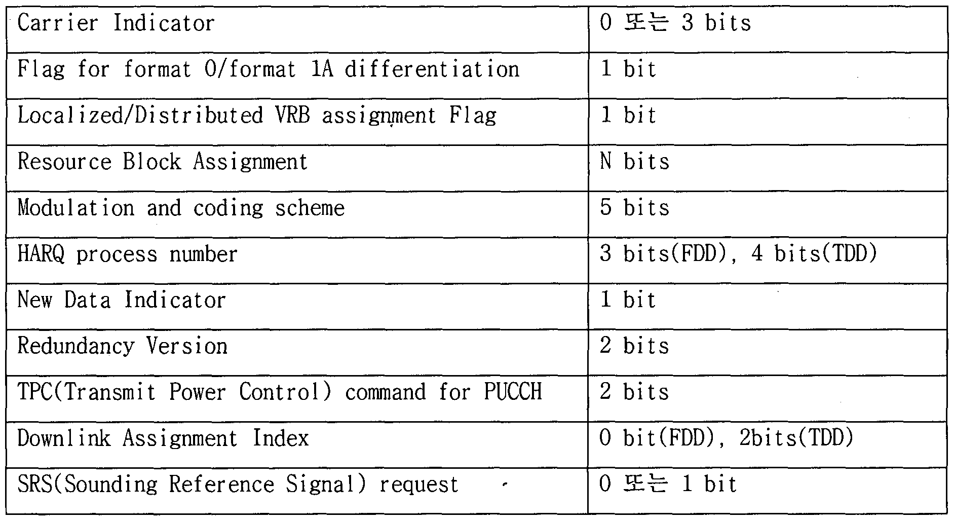
- DCI format 1A is a compact of one PDSCH codeword in one cell (compact) Refers to the DCI format used for scheduling. That is, the DCI format 1A may include control information used in the RAM 1 transmission such as single antenna transmission, single stream transmission, or transmission diversity transmission. Table 5 and Table 6 show an example of DCI format 1A defined in the existing 3GPP LTE / LTE-A standard.
- DCI format 1A including the control information as shown in Table 5 may be provided from the base station to the terminal through the PDCCH or E-PDCCH.
- DCI format 1A includes information scheduling the most basic downlink transmission (sending one PDSCH codeword to tank 1). Therefore, when a complex PDSCH transmission scheme such as tank 2 or more and / or a plurality of codeword transmissions is not performed correctly, it may be used for the purpose of supporting the most basic PDSCH transmission scheme (i.e., fal lback). .
- the uplink subframe may be divided into a control region and a data region in the frequency domain.
- a physical uplink control channel (PUCCH) including uplink control information is allocated.
- a physical uplink shared channel (PUSCH) including user data is allocated.
- PUCCH physical uplink control channel
- PUSCH physical uplink shared channel
- one UE does not simultaneously transmit a PUCCH and a PUSCH.
- the PUCCH for is allocated to an RB pair in a subframe. Resource blocks belonging to a resource block pair occupy different subcarriers for two slots.
- the resource block pair allocated to the PUCCH is said to be frequency-hopped at the slot boundary.
- a downlink signal is transmitted from any base station.
- the base station starts to transmit the downlink signal at point (a) of FIG.
- the downlink transmission signal undergoes propagation delay (PD) and starts to be received by any terminal at point (b).
- the terminal performs processing on the received signal.
- the receiving terminal buffers the received signal into a signal storage memory (0.5ms Buf f.) In one slot length and starts from the reception start point of the second 0.5tns slot in the subframe (point (c) of FIG. Decode the PDCCH to complete decoding of the PDCCH up to the second slot reception end point.
- the PDSCH is decoded according to the format indicated by the PDCCH.
- the UE performs less than 2ms from the start point to the completion point of decoding of the PDSCH.
- the terminal configures the decoding result as ACK / NACK information to perform transmission preparation and defines a delay required for a starting point (point (d) of FIG. 5) received from the base station within 1 ms.
- the time from when the base station transmits the downlink signal to the completion time of PDSCH decoding is defined as "one-way OTA (Over-The-Ai r) delay" and performs this within 3 ms as a reference.
- Delay from the time when the base station starts transmitting data on the 3GPP LTE system to the time when the base station starts receiving the ACK / NACK transmission of the wireless terminal is defined as "Roundtr ip OTA delay” and performs this to 1 ⁇ 2 s Make a reference.
- “Roundtr ip OTA delay” may be referred to as "ACK / NACK (A / N) RTT (Round Tr ip Time)”.
- Radio transmission and reception delay reference other values may be applied depending on the implementation of the terminal modem except for, for example, "Roundtr ip 0TA delay".
- 6 is a delay reference of downlink transmission and reception according to an embodiment of the present invention. It is a figure for demonstrating.
- FIG. 6 describes a delay reference of transmission and reception in terms of one-way OTA and Roundtr ip OTA delay. .
- downlink signals transmitted from the base station are received after being received by the user terminal through a transmission delay (PD).
- PD transmission delay
- Limitation of the interval and decoding time is required. Specifically, one 0FDM symbol interval sample buffering (0.071 ms Buf f.) Interval setting is required, and delays required for PDCCH decoding and PDSCH decoding are reduced by 1/4 and 1/5, respectively, as compared to FIG. 5. Required.
- delay according to ACK / NACK transmission should be excluded. If AC / NAC transmission is applied, the total delay of 1.5ms can be set as the target value.
- PDSCH decoding delay reduction TTKTransmit Time Interval
- subframe that is a unit that the packet scheduler schedules to limit the received processor event in symbol units and to limit the size of data information targeted for channel decoding. You can limit the size of the time period in (subframe).
- PDCCH decoding delay reduction limiting the PDCCH transmission symbol to define the PDCCH decoding delay and subsequent PDSCH decoding start point as quickly as possible or multiple downlink data transmission subframes over any user specific PDCCH Can deliver their scheduling information.
- Exclusion of user terminal ACK / NACK transmission ARQ (Automatic Repeat) on Layer 2 to determine the probability of error in downlink data transmission through enhanced downlink network radio node transmission performance and enhanced user terminal downlink signal reception performance "Roundt r ip 0TA delay" can be reduced by more than 0.5ms by excluding the ACK / NACK transmission under the condition that the request) processing alone is sufficient.
- the user-specific downlink-uplink transmission resource configuration (in order to increase the efficiency of the frequency band use and more smoothly support the differential up-downlink data asymmetry according to the service, application of the user unit)
- Fully Flexible UE-speci fic TDD (F2 UE-speci fic TDD) is proposed and effectively implements and applies a full duplex radio that performs simultaneous transmission and reception within a single frequency band. Describe how to do it.
- FIG. 7 illustrates a transmission resource structure in a 3GPP LTE system.
- 14 consecutive OFDM symbols are designated as one transmission unit in the case of a general cyclic prefix (CP) in 3GPP LTE and this is called a subframe.
- the length of the subframe is lnis and the LTE system performs user specific transmission data packet scheduling in units of 1ms subframes and defines this as a transmission time interval ( ⁇ ), and this unit becomes a 1ms subframe.
- ⁇ transmission time interval
- Ten of these subframes are bundled and defined again as a radio frame, and the total radio frame length is 10ms.
- FIG 8 illustrates a transmission resource structure according to an embodiment of the present invention.
- the present invention proposes a new transmission resource structure different from the existing subframe.
- a subframe consisting of N (where N ⁇ l) OFDM symbols is defined.
- an arbitrary radio frame structure is defined by combining M subframes each consisting of N OFDM symbols and P special symbols (SS) for a control physical signal or a control information transmission channel.
- the number M of repeating the new subframe in the legacy subframe transmission interval may be determined based on Equation 1 below.
- L is the number of 0FDM symbols of the legacy subframe
- N is the number of 0FDM symbols included in the new subframe.
- data may be transmitted through subframes, and a physical signal or a physical signal for control purposes may be transmitted through a special symbol for the purpose of data transmission and other control information.
- This new time resource transmission structure is specific per user. May be specified as a user specific transport structure. Or, it may be designated as a common transmission structure configured to be commonly applied to a cell or a system-wide user. Furthermore, the resource transmission structure may be configured to be limitedly applied over time.
- the resource transmission structure is a user common transmission structure, it may be indicated to the terminal through user common PDCCH or user common RRC signaling using system information for designation of a base station or network level.
- the resource transmission structure is a user specific transmission structure, it may be indicated to the UE through user specific PDCCH or user specific RRC signaling.
- the special symbols in the radio frame may be designed to be located at equal intervals in the radio frame or on a plurality of radio frames according to the purpose of transmitting a physical signal for measurement, detection, or information transmission purpose. Also, according to characteristics of information or signal to be transmitted, a plurality of special symbols may be continuously located at a specific position in a radio frame. Individual special symbols may be designed to be placed on a radio frame at irregular intervals.
- 9 and 10 illustrate the position of a special symbol in an example of a resource structure applied to the present invention.
- FIG. 10 proposes a resource structure in which two special symbols are consecutively arranged at the end of a radio frame as a resource structure applied to the present invention.
- Position of the special symbols on the time interval transmission resource structure proposed in the present invention is based on a special situation (for example, ACK / NACK transmission, reference signal transmission, etc.) given for each radio frame unit or a specific plurality of radio frames It may be arranged in units of radio frame sets.
- a special situation for example, ACK / NACK transmission, reference signal transmission, etc.
- the following method may be used to inform the terminal of the location of the special symbol. If the special symbol position of each radio frame has periodicity in a certain length unit, an index is generated for each pattern for the pattern of the special symbol position within the corresponding period. You can give it.
- a control information parameter in the form of a bitmap (bi t-map) in units of radio frames may be used.
- the base station can be delivered using RRC signaling, can be delivered through a downlink physical data channel using a MAC CE (control element), can also be delivered to the PDCCH,
- the new time interval transmission resource structure proposed in the present invention can be specified in a user specific transmission structure that is specified by the user unit in the frequency division duplex (Frequency division duplex (FDD)), the entire cell user It may be specified as a common transmission structure that is applied for In addition, the new time interval transmission resource structure may be applied to both the downlink transmission band and the uplink transmission band, or may be applied to only one of the transmission bands.
- FDD frequency division duplex
- the new time interval transmission resource structure is specified in units of users. It may be designated as a user specific transmission structure, or may be designated as a common transmission structure applied to an entire cell user. Further, the new time interval transmission resource structure may be applied to both a downlink resource and a downlink resource for the specific transport structure or the common transport structure, or may be applied only to a resource during one of two transmissions. have.
- the downlink transmission resource and the uplink transmission resource shown in FIG. 8 to FIG. 10 may be designated in units of radio frames, and in units of subframes within a radio frame. It can also be specified as. That is, the time interval transmission resource structure proposed by the present invention may be independently applied to an uplink transmission resource and a downlink transmission resource by using an independent parameter. The independent parameter may be delivered using a physical control channel or through RRC signaling. Meanwhile, the time interval transmission resource structure may be simultaneously applied to the uplink transmission resource and the downlink transmission resource according to the system application method. In this case, the time interval resource structure may be commonly applied to the uplink transmission resource and the downlink transmission resource by using one parameter, and the one parameter may be delivered to the terminal through a physical control channel or RRC signaling.
- the time interval transmission resource structure proposed by the present invention is defined such that a special symbol is included in the radio frame separately from the subframe.
- the special symbol may be utilized to transmit special cell common or user specific control information. It may be utilized to transmit a special sal common or user specific physical signal (pilot, reference signal, synchronization signal, etc.) for the purpose of measuring or detecting the terminal.
- the base station transmits the PDCCH to the terminal through a special symbol, the terminal may receive a target physical channel in the symbol.
- the PDCCH may include user common control information or user specific control information to be transmitted from the base station or any network radio node to the user terminal through downlink.
- the PDCCH used at this time may be designed on a frequency resource on one special symbol. If a plurality of special symbols are used, they may be designed on a plurality of symbol resources and frequency resources.
- the base station may transmit a downlink synchronization physical signal transmitted for the purpose of obtaining the downlink reception synchronization of the user terminal through one or more special symbols.
- the downlink synchronization physical signal may be, for example, a primary synchronization signal (PSS) and a secondary synchronization signal (SSS) in 3GPP LTE.
- PSS primary synchronization signal
- SSS secondary synchronization signal
- the position of the special symbol used for the synchronization signal transmission in any radio frame on the time interval transmission resource may be designated by the user. In this case, the location of the special symbol can be permanently designated by the base station and the terminal without additional signaling.
- the base station may transmit the downlink channel measurement pilot through a special symbol.
- a user may use a downlink channel measurement pilot for the purpose of system downlink control including supporting packet scheduler time-frequency resource setting and transmission scheme determination for a wireless channel on a wireless packet transmission system. It may be transmitted through one or more special symbols defined separately from the data channel transmission interval.
- the terminal may perform radio channel measurement using the pilot through the corresponding special symbol.
- a basic TDM or FDM multiple pilot resource pattern multiplexing method may be applied.
- a multiplex pilot resource pattern multiplexing method of a CDM method may be applied by applying a time interval orthogonal code application or a frequency interval orthogonal code application.
- the base station may define a special symbol so that the user terminal measures the interference signal.
- the user terminal may measure downlink reception interference signals generated between other network radio nodes or other terminals other than the network radio node (or base station) that the user terminal serves through one or more special symbols.
- a terminal that is being served through any network wireless node may apply a method of receiving a specific signal (which may define a pilot or reference signal) of neighboring network wireless nodes (or base stations) through the corresponding symbol.
- the corresponding network radio node (or base station) may exclude the transmission of radio signals in all subcarrier resources or some designated subcarrier resources in special symbols on time interval transmission resources used for transmission.
- a signal transmitted in a special symbol on multiple network radio nodes may be designated as a down channel measurement pilot (or reference signal), and a specific pilot pattern or all subcarrier resources within that symbol may be null to exclude transmission of radio signals.
- the terminal may perform an interference measurement operation in a situation in which the serving network wireless node transmits a signal by applying a specific resource pattern of a specific channel specific pilot (or reference signal).
- Downlink ACK / NACK signal transmission for uplink data transmission may be defined as a physical channel on any special symbol.
- the uplink data receiving network radio node (or base station) transmits a downlink ACK / NACK signal through a corresponding special symbol, and detects a system physical layer error so that a user terminal transmitting the uplink data receives the ACK / NACK through the corresponding special symbol. You can define corrective mechanism behavior.
- Downlink massive MIM0 beam scanning signal transmission massive in a wireless network node (or base station) to which the time interval transmission resource structure proposed in the present invention is applied.
- the network radio node or base station
- the user terminal may perform the operation of detecting the reception through the special symbol.
- Uplink synchronization signal transmission when the new time interval transmission resource structure according to the present invention is applied to the uplink transmission frame structure, the uplink synchronization signal of the user terminal (for example, PRACH preamble in 3GPP LTE ) May be transmitted in one special symbol length or a plurality of special symbol lengths.
- the uplink synchronization signal of the user terminal for example, PRACH preamble in 3GPP LTE
- the uplink channel sounding signal of the user terminal may be transmitted through a special symbol on the new time interval transmission resource structure according to the present invention. If the base station instructs transmission of the uplink channel sounding signal, the base station adds a channel sounding transmission indicator to the user specific uplink data transmission grant PDCCH at an arbitrary point before a corresponding length of the special symbol. You can trigger the sounding signal.
- the network may inform the transmission time of the channel sounding signal through a higher layer signal (eg, RRC signaling) in order to support more flexible operation.
- the predetermined length may be designated in units of radio frames or subframes.
- a transmission time of the channel sounding signal may be designated using a parameter through RRC signaling.
- the terminal may inform the terminal in advance of the time and resource configuration of the user specific channel sounding signal transmission attempt using the parameter.
- the timing and resource configuration may be specified and informed by a parameter.
- Uplink physical control channel transmission Uplink control information of any user terminal may be transmitted using an uplink physical control channel transmitted through one or a plurality of special symbols.
- the uplink control information of the user terminal that can be transmitted on the special symbol may be defined as follows.
- Method 1 One uplink physical control channel supporting error occurrence constraints required for each information on a bit size of a wide range of uplink control information may be defined and commonly applied to each control information case. .
- Method 2 For the case where the difference between the bit size of the individual uplink control information and the required error occurrence rate constraint is largely defined, the maximum possible control information bit size and error requirement of the corresponding information for each control information is defined. Supporting individual uplink physical control channels can be defined and transmitted through one or a plurality of special symbols.
- the base station may measure the uplink reception interference signal of another base station or a user terminal through one or more special symbols.
- the user terminal may measure downlink reception interference signals generated between other base stations or other terminals other than the base station served by the user terminal through one or more special symbols.
- any multi-user terminal or any base station may transmit a special pilot (or reference signal or signature) for the purpose of interference measurement using one or more special symbols.
- the base station can determine the surrounding interference situation by receiving and detecting the signal.
- the base station may exclude the pilot transmission through the special symbols of the user terminals that are the counterpart of the uplink reception, and for this purpose, a specific pilot pattern or all subcarrier resources within the symbol may be specifically defined as a null power pilot.
- FIG. 11 shows a time interval transmission resource structure for the purpose of interworking within an arbitrary FFT / IFFT size as an example of a resource structure applied to the present invention.
- a subframe including N (where N ⁇ l) OFDM symbols is defined.
- a random radio frame structure is defined by combining M subframes each consisting of N OFDM symbols and P special symbols (SS) for a control physical signal or a control information transmission channel.
- the subframe consisting of the N OFDM symbols is one packet slot
- a subframe in TTI which is a scheduling unit of the scheduler
- TTI which is a scheduling unit of the packet scheduler
- a subframe corresponding to a TTI which is an existing skelling unit is referred to as a legacy subframe.
- the CP length and the OFDM symbol length of the wireless communication system are defined to be the same.
- the present invention defines an improved subframe to reduce the radio transmission / reception delay.
- the number of OFDM symbols included in the enhanced subframe may be determined based on the one-way 0TA or Roundtr ip 0TA delay that is desired in the present invention. That is, the desired one-way 0TA delay or roundtr ip 0TA delay value is reduced compared to the 0TA delay value shown in FIG. 5.
- N may be determined by Equation 2 below.
- N corresponds to the minimum integer value larger than the value obtained by dividing the 0TA delay of the enhanced system by the 0TA delay of the legacy system.
- the 0TA delay of the enhanced system corresponds to the desired One-way 0TA delay or Roundtr ip 0TA delay value.
- the 0TA delay in the legacy system corresponds to the 0TA delay value in the system to which the new time resource structure is not applied.
- the 0TA delay of the enhanced system is designed to be 1/4 of the OTA delay in the existing legacy system, then N is 3. That is, the one enhanced subframe may be set to include three 0FDM symbols.
- the number P of special symbols included in the one legacy subframe may be determined by Equation 3 below.
- L is the number of 0FDM symbols included in a legacy subframe that is a subframe of the legacy system, and mod is an operator, where L is the remainder of L divided by N Indicates. That is, p corresponds to the remainder of L divided by N.
- the number P of special symbols included in the one legacy subframe may be determined by Equation 4 below.
- M corresponds to the number of transmissions of the enhanced subframe within the transmission interval of the legacy subframe.
- the improved subframe may be defined to include three OFDM symbols in consideration of the efficiency of such data resources.
- the CP length and the OFDM symbol length of the wireless communication system are defined to be the same. Define to include four enhanced subframes within the 1ms subframe length, which is a TTI unit of the existing wireless communication system. Four enhanced subframes and two special symbols are included in a 1ms unit length.
- the description of the present invention describes a case in which the two special symbols are used for PDCCH transmission purpose of transmitting control information of downlink transmission scheduling to a user terminal.
- the use of the special symbol is not limited to the PDCCH transmission, and may be used for various purposes as described above.
- FIG. 12 is a diagram for explaining a method of using a special symbol for PDCCH transmission as an embodiment of the present invention.
- the special symbols may be used for PDCCH transmission to realize a time interval transmission resource structure for a low transmission delay purpose.
- the time interval transmission resource structure is assumed to match with the existing frame structure of 3GPP LTE as shown in FIG. Referring to FIG. 12, the special symbol located first on the ln) s interval transmission resource structure may be used for a common resource setting purpose with the PDCCH transmission resource interval of 3GPP LTE. Any user terminal applying the interval resource structure at low transmission delay may perform blind decoding using the same method as the conventional PDCCH decoding method in the first special symbol.
- PDCCH transmission symbol interval length (or PDCCH symbol interval length inferred from PDSCH transmission start symbol index) designated as CFI information or RRC parameter of PCFICH of 3GPP LTE is one symbol (see FIG. 12 (a)) or It can be fixedly fixed by two symbols (refer to (b) of FIG. 12).
- the user terminal grasps information necessary for PDSCH reception for the first, second, third and fourth enhanced subframes, and the information. Decoding may be performed on the received PDSCH based on the. Information necessary for PDSCH reception is as follows.
- Control information indicating an enhanced subframe in which a PDSCH should be received by any user terminal An index or bit map for cases where enhanced subframe scheduling is possible (eg, FIG. 12) In the case of 4 bits) control information can be defined.
- Such control information may be transmitted to the user terminal via one or more individually decoded PDCCH transmitted on one or two designated special symbols.
- PDCCH configuration methods are proposed as follows.
- Method 1 The base station can transmit all the control information required for data reception within the entire lnis interval on the payload of one PDCCH.
- the user terminal may blind decode one PDCCH for receiving downlink data.
- the base station is a total of N enhanced subframes in the PDCCH transmission period
- the control information required for data reception described above can be divided into M ( ⁇ N) PDCCHs and transmitted.
- the user terminal may blind decode M PDCCHs for downlink data reception based on a pre-RCC configuration or a dynamic indication.
- PDCCH for transmitting the control information related to downlink data channel transmission for the first and second enhanced subframes in a payload and the control information for downlink data channel transmission for the third and fourth enhanced subframes.
- the PDCCH transmitting the payloads in the payload may be transmitted to the user terminal.
- the user terminal may perform blind decoding on the two PDCCHs for receiving the downlink data.
- Control information necessary for receiving the downlink data for each of all N enhanced subframes within a PDCCH transmission period may be transmitted by being divided into N PDCCHs.
- the user terminal may blind decode the N PDCCHs. For example, in FIG. 12, the user terminal may blind decode four PDCCHs for decoding a PDSCH of a subsequent enhanced subframe.
- the frequency resource settings of the PDSCHs of the four enhanced subframes appear to be the same, but this is only an example and the present invention is not limited thereto.
- Frequency transmission resources of different PDSCHs can be designated for each enhanced subframe.
- the frequency resource of the PDSCH may be configured in units of some plurality of enhanced subframes.
- the frequency resources of PDSCHs transmitted to any user terminal on the first and second enhanced subframes are the same and the PDSCHs transmitted to any user terminal on the third and fourth enhanced subframes. The manner in which the frequency resources are set identically can be applied.
- Control information related to transmission scheme designation such as a related MCS and a multi-antenna MIM0 transmission scheme are also the same when the frequency resources of individual PDSCHs transmitted to a user terminal through a plurality of enhanced subframes are the same. Can be set.
- Control information may be defined in consideration of the situations listed above.
- the control information for PDSCH reception may be defined as control information that is divided into enhanced subframe units, or may be defined as one control information commonly applied on one or more or all enhanced subframes.
- the second special symbol may be used for one purpose of the above-described objects described in the present invention. That is, in case of (b) of FIG. 12, the second special symbol includes downlink synchronization signal transmission, downlink channel measurement pilot (or reference signal) transmission described in the present invention, interference signal measurement utilization of the terminal, and uplink Downlink ACK / NACK signal transmission for data transmission, it can be utilized for downlink massive MIM0 beam scanning signal transmission. Accordingly, in the second special symbol, the base station may transmit a physical signal associated with each utilization scheme, and the user terminal may perform reception detection measurement of the signal.
- a downlink ACK / NACK signal for uplink data transmission may be transmitted by being multiplexed with PDCCHs on a special symbol used for decoding of the PDCCH and a user terminal.
- PDCCHs on a special symbol used for decoding of the PDCCH and a user terminal.
- it may be configured in the same manner as the PHICH channel transmission method and the user terminal reception method of the existing wireless communication system.
- FIG. 13 is a diagram for describing a method of using a special symbol for PDCCH transmission as another embodiment of the present invention.
- a PDCCH in a 1 ms period may be transmitted through a first special symbol resource in a 1 ms period to signal downlink data reception related control information of an arbitrary terminal.
- the time interval transmission resource structure is assumed to match with the existing frame structure of 3GPP LTE as shown in FIG.
- the base station may transmit the PDCCH through a special symbol resource specified in the seventh symbol position.
- the PDCCH may include scheduling information for supporting data channel decoding of a UE for a PDSCH transmitted through subsequent downlink enhanced subframes within a 1 ms designated period.
- the frequency resource of the second special symbol in the 1 ms period may be defined as the entire downlink system band or may be defined as a partial frequency resource band.
- the corresponding band of the special symbol may be designated in the following manner.
- the frequency band for the corresponding PDCCH transmission of the second special thimble may be designated as a frequency band designated in the most recent enhanced subframe before the second special symbol in the corresponding 1ms interval.
- the most recent enhanced subframe is scheduled to be incremented by enhanced subframe # 1 and enhanced subframe # 2 shown in FIG. 13.
- downlink transmission scheduling of the enhanced subframe # 3 and the enhanced subframe # 4 transmitted using the second special symbol within the lms interval is performed by the enhanced subframe # 1 and the improved subframe # 2 before the second special symbol. It is performed on the premise that at least one downlink data is transmitted.
- the terminal if the terminal does not detect the downlink data channel-related PDCCH for the terminal through the first special symbol of the designated period (that is, 1ms interval of FIG. 13), the terminal is second Assuming that a special symbol does not have a PDCCH to be decoded, it may not perform decoding on a second special symbol resource. Failure to detect the PDCCH may mean that there is no PDSCH to be received by the UE in enhanced subframe # 3 and enhanced subframe # 4. Therefore, the UE may not perform data channel decoding on the enhanced subframe # 3 and the enhanced subframe # 4.
- Method 2 The base station transmits at least one PDCCH through the first special symbol, the terminal receiving the decoding target frequency resource control information of the second special symbol through the demodulation decoding of the corresponding physical control channel Can be obtained.
- the PDCCH may include control information related to reception and transmission of a downlink or uplink data channel. If the base station transmits at least one or more PDCCHs including control information for a specific terminal through the first special symbol, the frequency resource information of the second special symbol is controlled in the payloads of all of the corresponding PDCCH or a specific part of the payload It can be included in the information and transmitted.
- the enhanced subframe index for scheduling the downlink or uplink data channel may be selected in ascending or descending order.
- a specific PDCCH transmitted from a base station to a terminal may have an attribute of control information indicating a result of uplink transmission scheduling to the terminal. This can be expressed as an uplink grant PDCCHOJpl ink Grant Physical Downl Ink Control Channel).
- the uplink transmission resource structure may also be applied to a structure for the purpose of low transmission delay.
- 3GPP LTE subframe 1ms which is a basic form of the time interval transmission resource structure of FIG. 11, may be applied.
- the position of the special symbol applied to the uplink may be applied differently according to the purpose of use.
- the time interval transmission resource structures proposed in FIG. 14 are applied for uplink transmission, in some cases, the time interval transmission resource structures may be applied to the downlink transmission resource structure according to a special use of a special symbol. Similarly, the time interval transmission resource structure for the downlink application purpose described in FIGS. 11 and 12 may be applied for uplink transmission as a whole to support a special use of a special heartbeat.
- the resource of the special symbols of a specific position proposed in FIG. 14 is one of an example of the uplink synchronization signal transmission, the uplink channel sounding signal transmission, the PUCCH transmission, and the physical signal transmission use case of the interference signal measurement of the terminal described in the present invention. It can be used to transmit physical signals for the purpose.
- Channel transmission scheme may be applied.
- the time interval transmission resource structure type is based on a general CP application case of 3GPP LTE that configures an lms subframe with 14 OFDM symbols, but is not limited thereto. That is, in case of an extended CP of 3GPP LTE, the proposals of the present invention may be applied based on a time interval transmission resource structure based on 12 OFDM symbols.
- FIG. 15 illustrates a resource structure according to the present invention when the extended CP.
- FIGS. 15A and 15B does not include a special symbol unlike the above-described resource structure.
- FIG. 15A illustrates a time interval transmission resource structure when three OFDM symbols are configured as one low delay subframe (LL-subframe) like a normal CP
- FIG. 15B Proposes a time interval transmission resource structure configured to include four 0FDM symbols with a general CP and one LL-subframe.
- (e) and (f) represents a time interval transmission resource structure defining three and four special thimbles, respectively.
- the specific positions of the special symbols in the individual time interval transmission resource structures shown in (c) to (f) of FIG. 15 may be set to forms other than those shown in FIG. 15 according to the purpose of using the special symbols.
- the description of the operation of the network radio node (or base station) and the user terminal according to the use of all the special symbols described above with respect to the general CP and the user terminal of the present invention is specifically set for the case of the extended CP The same can be applied to the transmission resource structure.
- FIG. 16 illustrates a block diagram of a communication device according to an embodiment of the present invention.
- a wireless communication system includes a base station (BS) 110 and a terminal (UE) 120.
- BS base station
- UE terminal
- the wireless communication system includes a relay
- the base station or the terminal may be replaced with a relay.
- a transmitter may be part of the base station 110 and a receiver may be part of the terminal 120.
- a transmitter may be part of the terminal 120 and a receiver may be part of the base station 110.
- the base station 110 includes a processor 112, a memory 114, and a radio frequency (RF) unit 116.
- Processor 112 may be configured to implement the procedures and / or methods proposed in the present invention.
- the memory 114 is connected with the processor 112 and stores various information related to the operation of the processor 112.
- the RF unit 116 is connected with the processor 112 and transmits and / or receives a radio signal.
- the terminal 120 is a processor 122, a memory 124 And an RF unit 126.
- the processor 122 may be configured to implement the procedures and / or methods proposed in the present invention.
- the memory 124 is connected with the processor 122 and stores various information related to the operation of the processor 122.
- the RF unit 126 is connected with the processor 122 and transmits and / or receives a radio signal.
- Embodiments described above are the components and features of the present invention are combined in a predetermined form. Each component or feature is to be considered optional unless stated otherwise. Each component or feature may be embodied in a form that is not combined with other components or features. In addition, it is also possible to configure the embodiments of the present invention by combining some components and / or features. The order of the operations described in the embodiments of the present invention may be changed. Some components or features of one embodiment may be included in another embodiment, or may be replaced with other components or features of another embodiment. It is obvious that the claims may be combined to form new embodiments by combining claims that do not have an explicit citation in the claims or by post-application correction.
- a specific operation described as performed by a base station may be performed by an upper node in some cases. That is, it is obvious that various operations performed for communication with the terminal in a network including a plurality of network nodes including a base station may be performed by the base station or other network nodes other than the base station.
- a base station may be replaced by terms such as fixed station, Node B, eNode B (eNB), and access point.
- the terminal may be replaced with terms such as UE Jser Equipment (MS), Mole le Stat ion (MS), Mole le Subscr iber Stat ion (MSS).
- Embodiments according to the present invention may be implemented by various means, for example, hardware, firmware (f irmware), software or a combination thereof.
- an embodiment of the present invention may include one or more ASICs ppl icat ion speci f ic integrated circuits, DSPs (digi tal signal processors), DSPDs (digi tal signal processing devices), and PLDs (PLDs).
- ASICs ppl icat ion speci f ic integrated circuits
- DSPs digi tal signal processors
- DSPDs digi tal signal processing devices
- PLDs PLDs
- FPGAs programmable logic devices
- FPGAs yield programmable gate arrays (FPGAs), processors, controllers, microcontrollers, microprocessors, and the like.
- an embodiment of the present invention is the above It may be implemented in the form of modules, procedures, functions, etc. that perform the functions or operations described in.
- Software code may be stored in a memory unit and driven by a processor.
- the memory unit may be located inside or outside the processor, and may exchange data with the processor by various known means.
- the present invention can be used in a terminal, base station, or other equipment of a wireless mobile communication system.
Landscapes
- Engineering & Computer Science (AREA)
- Signal Processing (AREA)
- Computer Networks & Wireless Communication (AREA)
- Quality & Reliability (AREA)
- Databases & Information Systems (AREA)
- Mobile Radio Communication Systems (AREA)
- Time-Division Multiplex Systems (AREA)
Abstract
Description



Claims
Priority Applications (5)
| Application Number | Priority Date | Filing Date | Title |
|---|---|---|---|
| CN201580003213.2A CN105830383B (zh) | 2014-03-13 | 2015-02-26 | 用于在无线通信系统中发送和接收低延迟信号的方法及其装置 |
| JP2016552261A JP6578292B2 (ja) | 2014-03-13 | 2015-02-26 | 無線通信システムにおいて低い遅延のための信号送受信方法及びこのための装置 |
| KR1020167021895A KR20160132375A (ko) | 2014-03-13 | 2015-02-26 | 무선 통신 시스템에서 낮은 지연을 위한 신호 송수신 방법 및 이를 위한 장치 |
| US15/108,553 US10084586B2 (en) | 2014-03-13 | 2015-02-26 | Method for transmitting and receiving signal for low latency in wireless communication system and apparatus therefor |
| EP15762074.1A EP3119026A4 (en) | 2014-03-13 | 2015-02-26 | Method for transmitting and receiving signal for low latency in wireless communication system and apparatus therefor |
Applications Claiming Priority (2)
| Application Number | Priority Date | Filing Date | Title |
|---|---|---|---|
| US201461952150P | 2014-03-13 | 2014-03-13 | |
| US61/952,150 | 2014-03-13 |
Publications (1)
| Publication Number | Publication Date |
|---|---|
| WO2015137649A1 true WO2015137649A1 (ko) | 2015-09-17 |
Family
ID=54072038
Family Applications (3)
| Application Number | Title | Priority Date | Filing Date |
|---|---|---|---|
| PCT/KR2015/001872 Ceased WO2015137649A1 (ko) | 2014-03-13 | 2015-02-26 | 무선 통신 시스템에서 낮은 지연을 위한 신호 송수신 방법 및 이를 위한 장치 |
| PCT/KR2015/001871 Ceased WO2015137648A1 (ko) | 2014-03-13 | 2015-02-26 | 무선 통신 시스템에서 낮은 지연을 위한 신호 송수신 방법 및 이를 위한 장치 |
| PCT/KR2015/001981 Ceased WO2015137654A1 (ko) | 2014-03-13 | 2015-03-02 | 무선 통신 시스템에서 낮은 지연을 위한 신호 송수신 방법 및 이를 위한 장치 |
Family Applications After (2)
| Application Number | Title | Priority Date | Filing Date |
|---|---|---|---|
| PCT/KR2015/001871 Ceased WO2015137648A1 (ko) | 2014-03-13 | 2015-02-26 | 무선 통신 시스템에서 낮은 지연을 위한 신호 송수신 방법 및 이를 위한 장치 |
| PCT/KR2015/001981 Ceased WO2015137654A1 (ko) | 2014-03-13 | 2015-03-02 | 무선 통신 시스템에서 낮은 지연을 위한 신호 송수신 방법 및 이를 위한 장치 |
Country Status (6)
| Country | Link |
|---|---|
| US (3) | US20160380732A1 (ko) |
| EP (3) | EP3119025A4 (ko) |
| JP (2) | JP6578292B2 (ko) |
| KR (1) | KR20160132375A (ko) |
| CN (3) | CN105830383B (ko) |
| WO (3) | WO2015137649A1 (ko) |
Cited By (1)
| Publication number | Priority date | Publication date | Assignee | Title |
|---|---|---|---|---|
| JP2020500461A (ja) * | 2016-10-28 | 2020-01-09 | テレフオンアクチーボラゲット エルエム エリクソン(パブル) | 受信機固有の送信長さ |
Families Citing this family (41)
| Publication number | Priority date | Publication date | Assignee | Title |
|---|---|---|---|---|
| WO2015137649A1 (ko) | 2014-03-13 | 2015-09-17 | 엘지전자 주식회사 | 무선 통신 시스템에서 낮은 지연을 위한 신호 송수신 방법 및 이를 위한 장치 |
| US9800363B2 (en) * | 2014-06-18 | 2017-10-24 | Qualcomm Incorporated | NAICS signaling for advanced LTE features |
| US10404441B2 (en) * | 2014-11-11 | 2019-09-03 | Electronics And Telecommunications Research Institute | Method and apparatus for configuring transmission time interval in mobile communication system |
| US10958391B2 (en) * | 2014-11-18 | 2021-03-23 | Qualcomm Incorporated | Tone plans for wireless communication networks |
| US10342016B2 (en) | 2015-03-06 | 2019-07-02 | Nec Corporation | Radio station, radio terminal apparatus, and method for these |
| EP3944551B1 (en) | 2015-04-02 | 2025-10-22 | Samsung Electronics Co., Ltd. | Transmission and reception method and apparatus for reducing transmission time interval in wireless cellular communication system |
| KR102316775B1 (ko) | 2015-04-02 | 2021-10-26 | 삼성전자 주식회사 | 무선 셀룰라 통신 시스템에서 전송시간구간 감소를 위한 송수신 방법 및 장치 |
| US9832790B2 (en) * | 2015-09-23 | 2017-11-28 | At&T Intellectual Property I, L.P. | Methods and apparatus to transmit data in a connectionless mode |
| US10868645B2 (en) * | 2015-11-06 | 2020-12-15 | Huawei Technologies Co., Ltd. | Method and base station for transmitting downlink data |
| SG11201805353WA (en) * | 2016-02-03 | 2018-07-30 | Sony Corp | Terminal device, base station device, and communication method |
| JP6797283B2 (ja) * | 2016-08-10 | 2020-12-09 | パナソニック インテレクチュアル プロパティ コーポレーション オブ アメリカPanasonic Intellectual Property Corporation of America | ワイヤレス通信方法、装置、およびシステム |
| US10205581B2 (en) * | 2016-09-22 | 2019-02-12 | Huawei Technologies Co., Ltd. | Flexible slot architecture for low latency communication |
| CN107872892B (zh) * | 2016-09-28 | 2023-04-18 | 中兴通讯股份有限公司 | 一种无线资源分配方法及装置 |
| EP4661332A3 (en) * | 2016-11-30 | 2026-03-04 | Guangdong Oppo Mobile Telecommunications Corp., Ltd. | Information transmission method, and terminal device |
| CN108243496B (zh) * | 2016-12-26 | 2020-04-07 | 工业和信息化部电信研究院 | 一种帧结构和移动通信方法 |
| CN110169177B (zh) * | 2017-01-12 | 2022-12-30 | Lg 电子株式会社 | 在无线通信系统中发送和接收下行链路控制信息的方法及其设备 |
| CN110268665B (zh) * | 2017-02-05 | 2022-04-15 | Lg 电子株式会社 | 在无线通信系统中支持多个传输时间间隔的方法和装置 |
| US10506566B2 (en) * | 2017-03-02 | 2019-12-10 | Lg Electronics Inc. | Caused by transmission beam tracking of UE in wireless communication system and UE therefor |
| KR102711790B1 (ko) * | 2017-03-23 | 2024-10-02 | 샤프 가부시키가이샤 | 단말 장치, 기지국 장치, 통신 방법, 및, 집적 회로 |
| CN114745084B (zh) * | 2017-03-24 | 2024-06-28 | 韦勒斯标准与技术协会公司 | 无线通信系统中发送和接收控制信道的方法、装置和系统 |
| EP3602936B1 (en) * | 2017-03-24 | 2021-09-01 | Motorola Mobility LLC | Method and apparatus for receiving downlink data transmissions |
| KR102377379B1 (ko) * | 2017-04-26 | 2022-03-22 | 삼성전자 주식회사 | 무선 통신 시스템에서 상향링크 신호 전송 타이밍 설정 방법 및 장치 |
| US11368275B2 (en) | 2017-06-16 | 2022-06-21 | Electronics And Telecommunications Research Institute | Method for configuring bandwidth for supporting broadband carrier in communication system |
| JP2020526084A (ja) | 2017-06-23 | 2020-08-27 | アイディーエーシー ホールディングス インコーポレイテッド | 無認可スペクトルにおける制限を有する送信 |
| CN109392072B (zh) * | 2017-08-14 | 2021-08-03 | 普天信息技术有限公司 | 功率余量的计算方法 |
| US11343124B2 (en) | 2017-08-15 | 2022-05-24 | At&T Intellectual Property I, L.P. | Base station wireless channel sounding |
| US10834689B2 (en) | 2017-08-15 | 2020-11-10 | At&T Intellectual Property I, L.P. | Base station wireless channel sounding |
| US10638340B2 (en) | 2017-08-15 | 2020-04-28 | At&T Intellectual Property I, L.P. | Base station wireless channel sounding |
| US10432330B2 (en) | 2017-08-15 | 2019-10-01 | At&T Intellectual Property I, L.P. | Base station wireless channel sounding |
| US10091662B1 (en) | 2017-10-13 | 2018-10-02 | At&T Intellectual Property I, L.P. | Customer premises equipment deployment in beamformed wireless communication systems |
| US11032721B2 (en) | 2017-10-13 | 2021-06-08 | At&T Intellectual Property I, L.P. | Minimization of drive tests in beamformed wireless communication systems |
| CN109842922B (zh) * | 2017-11-29 | 2021-09-17 | 中国电信股份有限公司 | 重要客户保障方法、装置和系统 |
| RU2669264C1 (ru) * | 2018-01-12 | 2018-10-09 | Общество с ограниченной ответственностью "Радио Гигабит" | Станция радиорелейной связи с многоканальным радиочастотным модулем и непрерывным сканированием луча и способ электронного сканирования |
| CN110034853B (zh) * | 2018-01-12 | 2021-09-21 | 华为技术有限公司 | 信号传输方法、相关设备及系统 |
| US12382462B2 (en) | 2018-02-07 | 2025-08-05 | Lg Electronics Inc. | Method for transmitting and receiving downlink signal between terminal and base station in wireless communication system supporting unlicensed band, and device supporting same |
| CN115243375B (zh) | 2018-04-04 | 2026-05-26 | 华为技术有限公司 | 通信方法及装置 |
| US11018929B2 (en) * | 2018-07-20 | 2021-05-25 | Kt Corporation | Method and apparatus for transmitting uplink channel in unlicensed band |
| CN111278160B (zh) * | 2019-03-29 | 2022-05-20 | 维沃移动通信有限公司 | 一种映射方法、终端设备及网络侧设备 |
| US11082265B2 (en) | 2019-07-31 | 2021-08-03 | At&T Intellectual Property I, L.P. | Time synchronization of mobile channel sounding system |
| WO2021060953A1 (ko) * | 2019-09-27 | 2021-04-01 | 엘지전자 주식회사 | 무선통신시스템에서 sci 전송 관련 ue의 동작 방법 |
| US20250119880A1 (en) * | 2023-10-06 | 2025-04-10 | Acer Incorporated | Method and Communication Device for Handling a Communication with a Serving Cell |
Citations (2)
| Publication number | Priority date | Publication date | Assignee | Title |
|---|---|---|---|---|
| KR20080002901A (ko) * | 2005-03-30 | 2008-01-04 | 모토로라 인코포레이티드 | 통신 시스템 내의 왕복 대기시간 및 오버헤드를 줄이기위한 방법 및 장치 |
| KR20140018894A (ko) * | 2011-03-23 | 2014-02-13 | 엘지전자 주식회사 | 무선 통신 시스템에서 동적 서브프레임 설정 시 재전송 방법 및 이를 위한 장치 |
Family Cites Families (29)
| Publication number | Priority date | Publication date | Assignee | Title |
|---|---|---|---|---|
| EP1900133B1 (en) | 2005-07-01 | 2012-03-21 | Telefonaktiebolaget LM Ericsson (publ) | Arrangement and method relating to time division duplex transmission |
| WO2007074841A1 (ja) | 2005-12-28 | 2007-07-05 | Matsushita Electric Industrial Co., Ltd. | 無線送信装置及び無線送信方法 |
| US8369301B2 (en) * | 2007-10-17 | 2013-02-05 | Zte (Usa) Inc. | OFDM/OFDMA frame structure for communication systems |
| AU2008312350B2 (en) * | 2007-10-17 | 2013-09-19 | Zte (Usa) Inc. | OFDM/OFDMA frame structure for communication systems |
| CN101911534B (zh) * | 2007-11-07 | 2014-07-30 | 蔚蓝公司 | 具有后向兼容性的改进技术帧结构 |
| US8396068B2 (en) * | 2007-12-20 | 2013-03-12 | Lg Electronics Inc. | Method for transmitting data in wireless communication system |
| WO2009084925A1 (en) * | 2008-01-03 | 2009-07-09 | Lg Electronics Inc. | Frame for flexibly supporting heterogeneous modes and tdd/fdd modes, and method for transmitting signals using the same |
| US8159979B2 (en) * | 2008-01-11 | 2012-04-17 | Lg Electronics Inc. | Enhanced TDD frame structure |
| US8537763B2 (en) | 2008-06-30 | 2013-09-17 | Motorola Mobility Llc | Frame allocation to support legacy wireless communication protocols on uplink transmission |
| KR101507852B1 (ko) * | 2008-08-28 | 2015-04-07 | 엘지전자 주식회사 | 서로 다른 길이의 순환전치부를 갖는 서브프레임을 다중화하는 프레임 구성방법 |
| RU2525084C2 (ru) * | 2008-11-14 | 2014-08-10 | Панасоник Корпорэйшн | Устройство терминала беспроводной связи, устройство базовой станции беспроводной связи и способ установки констелляции кластеров |
| CN103501217B (zh) | 2008-12-22 | 2017-01-04 | Lg电子株式会社 | 使用数据帧的数据传输方法 |
| WO2010074472A2 (ko) | 2008-12-22 | 2010-07-01 | (주)엘지전자 | 데이터 프레임을 이용한 데이터 송수신 방법 및 장치 |
| KR101530717B1 (ko) | 2009-01-08 | 2015-06-23 | 엘지전자 주식회사 | 무선통신 시스템에서 제어신호 전송방법 |
| KR101498066B1 (ko) * | 2009-04-14 | 2015-03-03 | 엘지전자 주식회사 | 무선 통신 시스템에서 데이터 전송 및 수신 방법 |
| KR101709511B1 (ko) | 2009-08-23 | 2017-02-23 | 엘지전자 주식회사 | 무선 통신 시스템에서 하향링크 신호 송신 방법 및 이를 위한 송신 장치 |
| CN102349252B (zh) * | 2010-01-08 | 2015-04-01 | 松下电器产业株式会社 | Ofdm发送装置、发送方法、ofdm接收装置和接收方法 |
| KR101684867B1 (ko) * | 2010-04-07 | 2016-12-09 | 삼성전자주식회사 | 공간 다중화 이득을 이용한 제어 정보 송수신 방법 |
| CN102238732A (zh) * | 2010-04-28 | 2011-11-09 | 中兴通讯股份有限公司 | 一种正交频分复用系统的无线资源分配、调度方法和装置 |
| KR101814396B1 (ko) * | 2010-04-28 | 2018-01-03 | 엘지전자 주식회사 | 경쟁 기반의 식별자를 이용한 상향링크 신호 전송 방법 |
| US9172513B2 (en) * | 2010-10-11 | 2015-10-27 | Qualcomm Incorporated | Resource assignments for uplink control channel |
| JP5487139B2 (ja) * | 2011-02-21 | 2014-05-07 | 日本電信電話株式会社 | 帯域割当方法及び受動光通信網システム |
| WO2012165877A2 (ko) | 2011-05-31 | 2012-12-06 | 엘지전자 주식회사 | 향상된 물리하향링크제어채널영역을 검색하는 방법 |
| US9247512B2 (en) | 2011-08-25 | 2016-01-26 | Ubiquiti Networks | Adaptive synchronous protocol for minimizing latency in TDD systems |
| JP5825353B2 (ja) * | 2011-09-28 | 2015-12-02 | 富士通株式会社 | 無線信号送信方法、無線信号送信装置及び無線信号受信装置 |
| US8718102B2 (en) | 2011-12-15 | 2014-05-06 | Intel Corporation | Minimalistic LTE maintenance timing advance method |
| CN103236910A (zh) * | 2013-03-25 | 2013-08-07 | 北京速通科技有限公司 | 一种专用短程通信协议的低速数据延迟响应方法 |
| US9313782B2 (en) * | 2013-05-08 | 2016-04-12 | Qualcomm Incorporated | Enhanced PDSCH operation |
| WO2015137649A1 (ko) | 2014-03-13 | 2015-09-17 | 엘지전자 주식회사 | 무선 통신 시스템에서 낮은 지연을 위한 신호 송수신 방법 및 이를 위한 장치 |
-
2015
- 2015-02-26 WO PCT/KR2015/001872 patent/WO2015137649A1/ko not_active Ceased
- 2015-02-26 US US15/039,006 patent/US20160380732A1/en not_active Abandoned
- 2015-02-26 EP EP15761486.8A patent/EP3119025A4/en not_active Withdrawn
- 2015-02-26 US US15/108,553 patent/US10084586B2/en active Active
- 2015-02-26 EP EP15762074.1A patent/EP3119026A4/en not_active Withdrawn
- 2015-02-26 CN CN201580003213.2A patent/CN105830383B/zh not_active Expired - Fee Related
- 2015-02-26 CN CN201580003556.9A patent/CN105874740A/zh active Pending
- 2015-02-26 KR KR1020167021895A patent/KR20160132375A/ko not_active Withdrawn
- 2015-02-26 JP JP2016552261A patent/JP6578292B2/ja active Active
- 2015-02-26 WO PCT/KR2015/001871 patent/WO2015137648A1/ko not_active Ceased
- 2015-03-02 US US15/116,194 patent/US10218486B2/en active Active
- 2015-03-02 WO PCT/KR2015/001981 patent/WO2015137654A1/ko not_active Ceased
- 2015-03-02 EP EP15762421.4A patent/EP3119014B1/en active Active
- 2015-03-02 JP JP2016552341A patent/JP6511464B2/ja active Active
- 2015-03-02 CN CN201580003269.8A patent/CN105830363B/zh not_active Expired - Fee Related
Patent Citations (2)
| Publication number | Priority date | Publication date | Assignee | Title |
|---|---|---|---|---|
| KR20080002901A (ko) * | 2005-03-30 | 2008-01-04 | 모토로라 인코포레이티드 | 통신 시스템 내의 왕복 대기시간 및 오버헤드를 줄이기위한 방법 및 장치 |
| KR20140018894A (ko) * | 2011-03-23 | 2014-02-13 | 엘지전자 주식회사 | 무선 통신 시스템에서 동적 서브프레임 설정 시 재전송 방법 및 이를 위한 장치 |
Non-Patent Citations (4)
| Title |
|---|
| CHINA TELECOM: "Discussion on multi-subframe scheduling", R1-131137, 3GPP TSG RAN WG1 #72BIS, 5 April 2013 (2013-04-05), CHICAGO, USA, XP050696766 * |
| HTC: "Discussion on TDD UL-DL Reconfiuration in TDD eIMTA Systems", RL-133252, 3GPP TSG RAN WG1 #74, 10 August 2013 (2013-08-10), Barcelona, Spain, XP050716410 * |
| SAMSUNG: "Considerations on Multi-Subframe Scheduling", R1-131023, 3GPP TSG RAN WG1 #72BIS, 5 April 2013 (2013-04-05), CHICAGO, USA, XP050696723 * |
| See also references of EP3119026A4 * |
Cited By (1)
| Publication number | Priority date | Publication date | Assignee | Title |
|---|---|---|---|---|
| JP2020500461A (ja) * | 2016-10-28 | 2020-01-09 | テレフオンアクチーボラゲット エルエム エリクソン(パブル) | 受信機固有の送信長さ |
Also Published As
| Publication number | Publication date |
|---|---|
| US10218486B2 (en) | 2019-02-26 |
| CN105830383B (zh) | 2020-01-10 |
| CN105830383A (zh) | 2016-08-03 |
| JP6578292B2 (ja) | 2019-09-18 |
| EP3119014A1 (en) | 2017-01-18 |
| US20170012747A1 (en) | 2017-01-12 |
| JP2017513273A (ja) | 2017-05-25 |
| WO2015137648A1 (ko) | 2015-09-17 |
| US20160330003A1 (en) | 2016-11-10 |
| EP3119025A1 (en) | 2017-01-18 |
| EP3119026A1 (en) | 2017-01-18 |
| US10084586B2 (en) | 2018-09-25 |
| EP3119014A4 (en) | 2017-10-25 |
| US20160380732A1 (en) | 2016-12-29 |
| CN105830363A (zh) | 2016-08-03 |
| KR20160132375A (ko) | 2016-11-18 |
| CN105874740A (zh) | 2016-08-17 |
| JP2017513275A (ja) | 2017-05-25 |
| EP3119014B1 (en) | 2019-07-17 |
| WO2015137654A1 (ko) | 2015-09-17 |
| EP3119025A4 (en) | 2017-10-25 |
| JP6511464B2 (ja) | 2019-05-15 |
| EP3119026A4 (en) | 2017-10-25 |
| CN105830363B (zh) | 2019-10-11 |
Similar Documents
| Publication | Publication Date | Title |
|---|---|---|
| JP6578292B2 (ja) | 無線通信システムにおいて低い遅延のための信号送受信方法及びこのための装置 | |
| JP6921181B2 (ja) | 無線通信システムにおいて端末が他の端末にデータを伝送する方法 | |
| KR101666286B1 (ko) | 무선통신 시스템에서 데이터 채널의 시작 위치 설정 방법 및 상기 방법을 이용하는 장치 | |
| KR102140744B1 (ko) | 무선 통신 시스템에서 무선 신호 송수신 방법 및 장치 | |
| EP3270526B1 (en) | Method for reducing transmission resource of control channel in short tti, and device using same | |
| JP5745182B2 (ja) | 無線通信システムにおいて制御情報伝送/獲得方法及び装置 | |
| KR20140122722A (ko) | 무선 통신 시스템에서 개선된 제어 채널 기반 동작 방법 및 장치 | |
| JP6321851B2 (ja) | 無線通信システムにおいて制御情報受信方法及び装置 | |
| WO2013100645A1 (ko) | 무선 통신 시스템에서 데이터 수신 방법 및 장치 | |
| KR20140082769A (ko) | 무선통신시스템에서 제어정보 송수신 방법 및 장치 | |
| WO2013048108A2 (ko) | 무선통신시스템에서 제어정보 획득 방법 및 장치 | |
| KR102078373B1 (ko) | 무선 통신 시스템에서 무선 신호 송수신 방법 및 장치 | |
| WO2015133860A1 (ko) | 무선 통신 시스템에서 제어 정보 전송 방법 및 장치 |
Legal Events
| Date | Code | Title | Description |
|---|---|---|---|
| 121 | Ep: the epo has been informed by wipo that ep was designated in this application |
Ref document number: 15762074 Country of ref document: EP Kind code of ref document: A1 |
|
| REEP | Request for entry into the european phase |
Ref document number: 2015762074 Country of ref document: EP |
|
| WWE | Wipo information: entry into national phase |
Ref document number: 2015762074 Country of ref document: EP |
|
| WWE | Wipo information: entry into national phase |
Ref document number: 15108553 Country of ref document: US |
|
| ENP | Entry into the national phase |
Ref document number: 20167021895 Country of ref document: KR Kind code of ref document: A |
|
| ENP | Entry into the national phase |
Ref document number: 2016552261 Country of ref document: JP Kind code of ref document: A |
|
| NENP | Non-entry into the national phase |
Ref country code: DE |