WO2015140916A1 - 車載機器のネジ構造 - Google Patents
車載機器のネジ構造 Download PDFInfo
- Publication number
- WO2015140916A1 WO2015140916A1 PCT/JP2014/057258 JP2014057258W WO2015140916A1 WO 2015140916 A1 WO2015140916 A1 WO 2015140916A1 JP 2014057258 W JP2014057258 W JP 2014057258W WO 2015140916 A1 WO2015140916 A1 WO 2015140916A1
- Authority
- WO
- WIPO (PCT)
- Prior art keywords
- screw
- hole
- vehicle
- fastened
- male
- Prior art date
- Legal status (The legal status is an assumption and is not a legal conclusion. Google has not performed a legal analysis and makes no representation as to the accuracy of the status listed.)
- Ceased
Links
Images






Classifications
-
- F—MECHANICAL ENGINEERING; LIGHTING; HEATING; WEAPONS; BLASTING
- F16—ENGINEERING ELEMENTS AND UNITS; GENERAL MEASURES FOR PRODUCING AND MAINTAINING EFFECTIVE FUNCTIONING OF MACHINES OR INSTALLATIONS; THERMAL INSULATION IN GENERAL
- F16B—DEVICES FOR FASTENING OR SECURING CONSTRUCTIONAL ELEMENTS OR MACHINE PARTS TOGETHER, e.g. NAILS, BOLTS, CIRCLIPS, CLAMPS, CLIPS OR WEDGES; JOINTS OR JOINTING
- F16B41/00—Measures against loss of bolts, nuts, or pins; Measures against unauthorised operation of bolts, nuts or pins
- F16B41/002—Measures against loss of bolts, nuts or pins
-
- F—MECHANICAL ENGINEERING; LIGHTING; HEATING; WEAPONS; BLASTING
- F16—ENGINEERING ELEMENTS AND UNITS; GENERAL MEASURES FOR PRODUCING AND MAINTAINING EFFECTIVE FUNCTIONING OF MACHINES OR INSTALLATIONS; THERMAL INSULATION IN GENERAL
- F16B—DEVICES FOR FASTENING OR SECURING CONSTRUCTIONAL ELEMENTS OR MACHINE PARTS TOGETHER, e.g. NAILS, BOLTS, CIRCLIPS, CLAMPS, CLIPS OR WEDGES; JOINTS OR JOINTING
- F16B5/00—Joining sheets or plates, e.g. panels, to one another or to strips or bars parallel to them
- F16B5/02—Joining sheets or plates, e.g. panels, to one another or to strips or bars parallel to them by means of fastening members using screw-thread
- F16B5/0275—Joining sheets or plates, e.g. panels, to one another or to strips or bars parallel to them by means of fastening members using screw-thread the screw-threaded element having at least two axially separated threaded portions
Definitions
- This invention relates to a screw structure for fixing an in-vehicle device to a vehicle.
- a screw is used to fix an in-vehicle device such as a display to a dashboard of a vehicle.
- an in-vehicle device such as a display to a dashboard of a vehicle.
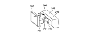
- the operator first slides the display 100 in the direction of the arrow X1 to place the housing 101 in the recess 201 of the design panel 200. Insert into.
- the operator sets and tightens the screws 203 in the through holes 202 provided on the upper surface of the design panel 200 as shown in FIG.
- the screw 203 is fastened, as shown in FIG. 17, the fastened portion 102 of the housing 101 is fixed to the design panel 200 by the screw 203.
- Patent Document 1 proposes a means for temporarily fixing a screw in order to reduce the trouble of setting the screw in the screw hole in the above-described attachment work.
- interference between the screw and the screw hole is proposed. There is no way to avoid it.
- the present invention has been made to solve the above-described problems, and an object thereof is to make an in-vehicle device detachable from a vehicle simply by loosening a screw.
- the screw structure of the in-vehicle device according to the present invention is formed in the in-vehicle device, and is to be fastened by being screwed into the screw hole through the through hole and the to-be-fastened portion having the through hole, the screw hole formed on the vehicle side.
- a first female screw portion having a male screw portion and a second male screw portion having a diameter larger than that of the first male screw portion, and the screw hole is screwed into the first male screw portion of the screw to fix the fastened portion to the vehicle side.
- the to-be-fastened portion has a second female screw portion that is screwed with the second male screw portion of the screw and holds the screw in a state of being removed from the screw hole when the in-vehicle device is removed.
- the screw structure of the in-vehicle device according to the present invention is formed in the in-vehicle device, and is to be fastened by being screwed into the screw hole through the through hole and the to-be-fastened portion having the through hole, the screw hole formed on the vehicle side.
- the screw structure of the in-vehicle device according to the present invention is formed in the in-vehicle device, and is to be fastened by being screwed into the screw hole through the through hole and the to-be-fastened portion having the through hole, the screw hole formed on the vehicle side.
- the to-be-fastened part slides in the direction perpendicular to the axial direction of the screw hole and disengages from the vehicle side.
- a male screw part and a cylindrical part formed between the head part and the male screw part and longer than the thickness of the fastened part.
- the first female thread part to be fixed to the side, and the through hole of the fastened part is screwed with the male thread part of the screw when removing the in-vehicle device, and the screw is removed from the screw hole. It has a 2nd female thread part which lets a part penetrate.
- the screw structure of the in-vehicle device according to the present invention is formed in the in-vehicle device, and is to be fastened by being screwed into the screw hole through the through hole and the to-be-fastened portion having the through hole, the screw hole formed on the vehicle side.
- It has a slope portion that has a through-hole side that is low and increases in the sliding direction of the fastened portion, and has a slope portion that pushes the head of a loose screw and pushes it up along with the slide when removing the in-vehicle device.
- the second female screw portion of the fastened portion is screwed with the second male screw portion of the screw so that the screw is removed from the screw hole.
- the screw does not interfere with the screw hole when the fastening part slides. Therefore, the vehicle-mounted device can be made removable from the vehicle simply by loosening the screw.
- the valve of the fastened portion is elastically contacted with the screw, and the screw is held in a state where it is removed from the screw hole when removing the in-vehicle device. Does not interfere with the screw holes. Therefore, the vehicle-mounted device can be made removable from the vehicle simply by loosening the screw.
- the second female screw portion of the through hole of the fastened portion is screwed with the male screw portion of the screw so that the screw is held out of the screw hole.
- the screw does not interfere with the screw hole when the fastened part slides. Therefore, the vehicle-mounted device can be made removable from the vehicle simply by loosening the screw.
- the vehicle-mounted device can be made removable from the vehicle simply by loosening the screw.
- FIG.1 (a) is the state which fastened the screw
- FIG.1 (b) and FIG.1 (c) are in the middle of loosening the screw.
- FIG. 1D shows a state in which the screw is completely loosened.
- FIG. 6 is a cross-sectional view showing a modification of the screw structure according to the first embodiment.
- FIG.5 (a) is a state before fastening a screw
- FIG.5 (b) is the state which fastened the screw
- FIG.5 (c) Is the state where the screw is completely loosened.
- 6 is a plan view illustrating a configuration example of a screw-structure valve according to Embodiment 2.
- FIG. 6 is a plan view illustrating a configuration example of a screw-structure valve according to Embodiment 2.
- FIG.8 (a) is a state before fastening a screw
- FIG.8 (b) is the state which fastened the screw
- FIG.8 (c) Is the state where the screw is completely loosened.
- FIG. 10 is a cross-sectional view showing a modified example of the screw structure according to Embodiment 3.
- FIG.11 (a) is the state which fastened the screw
- FIG.11 (b) is the state which loosened the screw completely
- FIG. 11 (d) show a state where the fastened portion is being slid.
- Drawing 12 (a) is a perspective view
- Drawing 12 (b) is a top view.
- Fig.13 (a) is a perspective view
- FIG.13 (b) is a top view.
- FIG. 16 is a diagram for explaining a process following the process in FIG. 15. It is a figure which shows the state in which the display was attached to the design panel by the side of the vehicle by the conventional method. It is a figure for demonstrating the process of removing a display from the design panel by the side of the vehicle by the conventional method.
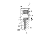
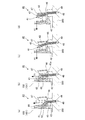
- FIG. 1 is a cross-sectional view showing a configuration of a screw structure 10 according to the first embodiment.
- FIG. 1A shows a state in which a screw 11 is fastened
- FIGS. 1B and 1C show a screw 11.
- FIG. 1 (d) shows a state in which the screw 11 is completely loosened.
- FIG. 2 is a cross-sectional view of the display 100 and the design panel 200 provided with the screw structure 10, and the same or corresponding parts as those in FIGS.
- the screw structure 10 according to Embodiment 1 two types of male screw portions having different diameters are formed on one screw 11.
- the first male screw portion 13 having a small diameter d13 is screwed into the first female screw portion 18 of the vehicle side screw hole 17 formed in the design panel 200 on the vehicle side.
- the second male screw portion 12 having a large diameter d12 is screwed into the second female screw portion 15 of the fastened portion 14 formed in the housing 101 of the display 100.
- the through hole 16 opened on the bottom surface of the fastened portion 14 is smaller in diameter than the second male screw portion 12 of the screw 11 and larger in diameter than the first male screw portion 13, and the peripheral portion of the through hole 16 is a seating surface of the screw 11. Become.
- the second female screw portion 15 of the fastened portion 14 is not used, and the first female screw portion 18 of the vehicle-side screw hole 17 and the first of the screw 11 are used.
- the male screw part 13 is used.
- the fastened portion 14 is fixed to the vehicle side by screwing the first female screw portion 18 of the vehicle-side screw hole 17 and the first male screw portion 13 of the screw 11.
- the screw 11 When the screw 11 is loosened when the screw 11 is loosened, the screw 11 is screwed by the first female screw portion 18 of the vehicle-side screw hole 17 and the first male screw portion 13 of the screw 11 as shown in FIG. Moving in the direction of the arrow Y1 (that is, the axial direction of the vehicle-side screw hole 17), the screw 11 is removed from the vehicle-side screw hole 17. At this time, when the screw 11 is removed from the vehicle-side screw hole 17 to some extent, the second female screw portion 15 of the fastened portion 14 and the second male screw portion 12 of the screw 11 are screwed together.
- the first female screw portion 18 of the vehicle-side screw hole 17 and the first male screw portion 13 of the screw 11 are screwed together for a while, and the second female screw portion of the fastened portion 14 is engaged. 15 and the second male screw portion 12 of the screw 11 continue to be screwed together.
- the first female screw portion 18 of the vehicle-side screw hole 17 and the first male screw portion 13 of the screw 11 are disengaged, and the second female screw portion 15 of the fastened portion 14 and the second male screw portion 12 of the screw 11 are connected. Only by screwing, the screw 11 moves in the direction of the arrow Y1.
- the screw 11 is completely removed from the vehicle-side screw hole 17 as shown in FIG.
- the screw 11 since the second male screw portion 12 of the screw 11 is screwed into the second female screw portion 15 of the fastened portion 14, the screw 11 is attached to the fastened portion 14.
- the height of the second female screw portion 15 is such that the screw 11 is completely removed from the vehicle-side screw hole 17 in a state where the second male screw portion 12 of the screw 11 is screwed to the second female screw portion 15. It should be a high position.
- the prior thread cutting of the 2nd female thread part 15 and the 1st female thread part 18 is unnecessary.
- the 2nd female thread part 15 may be formed over the inner wall whole periphery of the to-be-fastened part 14, and the 2nd female thread part 15 may be formed in the circumferential direction discontinuously.
- an inclined surface-shaped guide portion 19 may be formed at the lower end portion of the second female screw portion 15.
- the screw 11 includes the first male screw portion 13 and the second male screw portion 12 having a larger diameter than the first male screw portion 13, and the vehicle-side screw hole 17 is
- the first male screw part 13 of the screw 11 is screwed to fix the fastened part 14 to the design panel 200 on the vehicle side, and the fastened part 14 is a screw when the display 100 is removed.
- the second female screw portion 12 and the second female screw portion 15 for holding the screw 11 in a state of being removed from the vehicle-side screw hole 17.
- FIG. FIG. 5 is a cross-sectional view showing the configuration of the screw structure 20 according to the second embodiment.
- FIG. 5A is a state before the screw 21 is fastened
- FIG. 5B is a state where the screw 21 is fastened
- FIG. 5C shows a state in which the screw 21 is completely loosened.
- the screw structure 20 is formed on the housing 101 of the display 100 and the design panel 200 instead of the screw structure 10 shown in FIG.
- the basic configurations of the display 100 and the design panel 200 are the same as those in FIGS. 2 and 14 to 18.
- the screw 21 has a general shape having a head portion 22 and a male screw portion 23.
- the male screw portion 23 is screwed into a female screw portion 28 of a vehicle-side screw hole 27 formed in the design panel 200 on the vehicle side.
- the fastened portion 24 formed in the housing 101 of the display 100 includes a through hole 25 that allows the male screw portion 23 of the screw 21 to pass therethrough and a thin valve 26 that protrudes inward from the peripheral portion of the through hole 25. Is formed.
- the valve 26 is made of a resin material or a metal material, has an elastic force, and has a function of hooking and holding the screw 21. In the illustrated example, the thickness of the valve 26 is thinner than the thickness of the fastened portion 24, but it may be equal to or greater than that of the fastened portion 24 as long as the above function can be satisfied.
- the to-be-fastened part 24 and the valve 26 are fundamentally integral structure, even if it is a separate component, there is no problem.
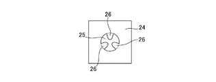
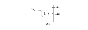
- FIG. 6 and 7 are plan views of the valve 26 as viewed from the direction of the arrow Y2 in FIG.
- three valves 26 are formed for one through hole 25.
- the valve 26 is formed over the entire circumference of the through hole 25.
- the diameter of the central hole 26a of the valve 26 is smaller than the diameter of the screw 21.
- the screw 21 enters and exits while expanding the central hole 26a of the valve 26. Is possible.
- FIG. 6 and FIG. 7 are examples, and there is no particular limitation on the size and number of the valves 26. An appropriate size and number may be set according to the size of the screw 21 and the like.
- the valve 21 is elastically contacted with the distal end portion, so that the screw 21 can be held.
- a tapping screw is used as the screw 21, it is not necessary to cut the female thread portion 28 in advance.
- the fastened portion 24 protrudes inward from the peripheral portion of the through hole 25 to elastically contact the screw 21, and the screw 21 is screwed to the vehicle side screw when removing the display 100.
- the valve 26 is configured to be held in a state of being removed from the hole 27.
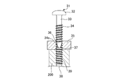
- FIG. 8 is a cross-sectional view showing the configuration of the screw structure 30 according to the third embodiment.
- FIG. 8A is a state before the screw 31 is fastened
- FIG. 8B is a state where the screw 31 is fastened
- FIG. 8C shows a state in which the screw 31 is completely loosened.
- This screw structure 30 is formed on the housing 101 of the display 100 and the design panel 200 instead of the screw structure 10 shown in FIG.
- the basic configurations of the display 100 and the design panel 200 are the same as those in FIGS. 2 and 14 to 18.
- a screw 31 is formed with a head portion 32, a cylindrical portion 33 without a screw thread, and a male screw portion 34 with a screw thread.
- the diameter d33 of the cylindrical portion 33 needs to be smaller than the diameter d34 of the male screw portion 34 (d33 ⁇ d34).
- the axial length t33 of the cylindrical portion 33 needs to be longer than the thickness t35 of the fastened portion 35 (t33> t35).
- a through-hole 36 is formed in the fastened portion 35 formed in the housing 101 of the display 100, and second female screw portions 37 corresponding to several pitches are formed in the through-hole 36.
- a vehicle-side screw hole 38 is formed in the design panel 200 on the vehicle side, and a first female screw portion 39 is formed in the vehicle-side screw hole 38. The second female screw portion 37 and the first female screw portion 39 are screwed into the male screw portion 34 of the screw 31.
- the first female screw portion 39 of the vehicle side screw hole 38 and the male screw portion 34 of the screw 31 are used.
- the fastened portion 35 is fixed to the vehicle side by screwing the first female screw portion 39 of the vehicle-side screw hole 38 and the male screw portion 34 of the screw 31.
- the cylindrical portion 33 of the screw 31 has no thread, the second female screw portion 37 of the fastened portion 35 is not used.
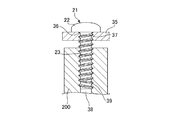
- the screw 21 shown as a reference example in FIG. 9 has a screw thread formed immediately below the head 22. That is, the male screw portion 23 is formed from directly below the head portion 22.
- the screw 21 is fastened to the second female screw part 37 of the through hole 36 in a state where a gap exists between the fastened part 35 and the design panel 200, the head 22 is caught on the edge of the through hole 36. Until then, the screw 21 rotates. However, since the male screw portion 23 and the second female screw portion 37 are screwed together, the screw 21 cannot be rotated. Therefore, a gap remains between the fastened portion 35 and the design panel 200, and the display 100 is rattled.
- the cylindrical portion 33 is not screwed into the second female screw portion 37 of the through hole 36, so that the fastened portion 35 is attached to the design panel 200.
- the screw 31 can rotate until it abuts. Therefore, no gap remains between the fastened portion 35 and the design panel 200.
- the diameter d33 of the cylindrical portion 33 is made smaller than the diameter d34 of the male screw portion 34, and the axial length t33 of the cylindrical portion 33 is made longer than the thickness t35 of the fastened portion 35. It is.
- the prior thread cutting of the 2nd female thread part 37 and the 1st female thread part 39 is unnecessary.
- the screw portion 34 and the screw portion 34 are in a state where the tip portion 34 a is completely removed from the vehicle-side screw hole 38 of the design panel 200.
- the to-be-fastened part 35 is made thick so that the 2nd female thread part 37 of the to-be-fastened part 35 may be screwed together.
- the screw 31 has the cylindrical portion 33 that is formed between the head portion 32 and the male screw portion 34 and is longer than the thickness of the fastened portion 35, and is a vehicle-side screw.
- the hole 38 has a first female screw portion 39 that is screwed into the male screw portion 34 of the screw 31 to fix the display 100 to the design panel 200, and the through hole 36 of the fastened portion 35 is a screw when the display 100 is removed.
- the screw 31 is screwed with the male screw 34 to hold the screw 31 in a state where it is removed from the vehicle-side screw hole 38, and the second female screw 37 for inserting the cylindrical portion 33 of the screw 31 is provided. Thereby, since the screw 31 does not interfere with the vehicle side screw hole 38 when the fastened part 35 slides, the display 100 can be removed from the design panel 200 only by loosening the screw 31.
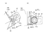
- FIG. 11A and 11B are cross-sectional views showing the configuration of the screw structure 40 according to the fourth embodiment.
- FIG. 11A shows a state where the screw 41 is fastened
- FIG. 11B shows a state where the screw 41 is loosened
- FIG. (C) and FIG.11 (d) are the states in the middle of the to-be-fastened part 44 sliding.
- 11A is a perspective view of the screw structure 40 of FIG. 11A
- FIG. 12B is a plan view thereof
- FIG. 13A is a perspective view of the screw structure 40 of FIG.
- a plan view is shown in FIG.
- the screw structure 40 is formed on the housing 101 of the display 100 and the design panel 200 instead of the screw structure 10 shown in FIG.
- the basic configurations of the display 100 and the design panel 200 are the same as those in FIGS. 2 and 14 to 18.
- the screw 41 has a general shape having a head portion 42 and a male screw portion 43.
- the male screw portion 43 is screwed into a female screw portion 49 of a vehicle-side screw hole 48 formed in the vehicle-side design panel 200.
- the fastened portion 44 formed in the housing 101 of the display 100 includes a through hole 45 that penetrates the male screw portion 43 of the screw 41, a long hole 46 that extends in one direction from the through hole 45, and a peripheral edge of the long hole 46. And a slope portion 47 is formed.
- the peripheral portion of the through hole 45 becomes a seating surface of the screw 41, and a step portion constituted by a head portion 42 and a male screw portion 43 is hooked.
- An elongated hole 46 extending in the sliding direction of the display 100 is connected to the through hole 45.
- a wall having an inclined upper surface is provided as a slope portion 47 on the peripheral edge of the long hole 46. The slope of the upper surface of the slope portion 47 is the lowest on the through hole 45 side and becomes higher in the direction of the arrow X2 that is slid when the display 100 is removed from the design panel 200.
- the detailed structure such as the position of the wall portion 47a contacting the head portion 42 of the screw 41 and the inclination angle of the upper surface of the slope portion 47 may be set according to the shape of each portion. For example, if the wall portion 47a is arranged at a position that is close to the edge of the head portion 42, shakiness in the sliding direction of the display 100 can be suppressed. Further, for example, if the inclination angle of the upper surface of the slope portion 47 is made steep, the screw 41 can be pulled out from the vehicle-side screw hole 48 with a short slide distance. However, if the inclination angle of the upper surface of the slope portion 47 is too steep, it becomes difficult for the head portion 42 of the screw 41 to be caught and go under the neck.
- the fastened portion 44 has an inclined surface shape that is low on the through-hole 45 side and becomes high in the sliding direction of the fastened portion 44 and removes the display 100.
- the head portion 42 of the loose screw 41 is hooked and is configured to have a slope portion 47 that pushes up along with the slide.
- the screw structure has been described taking the case where the display is attached to the design panel as an example.
- the screw structure is not limited to the display, and any in-vehicle device mounted on the vehicle may be used.
- orthogonal means substantially orthogonal, and arrows Y1,
- the angle formed by X2 may be an angle around 90 degrees as long as it is within the range where the above effect is achieved.
- the present invention can be freely combined with each embodiment, modified any component of each embodiment, or omitted any component in each embodiment. Is possible.
- the screw structure according to the present invention can make the in-vehicle device detachable from the vehicle simply by loosening the screw, so the in-vehicle device has a structure in which the sliding direction and the fastening direction of the screw are substantially orthogonal to each other. Suitable for screw structure used in
Landscapes
- Engineering & Computer Science (AREA)
- General Engineering & Computer Science (AREA)
- Mechanical Engineering (AREA)
- Fittings On The Vehicle Exterior For Carrying Loads, And Devices For Holding Or Mounting Articles (AREA)
Abstract
ネジ構造10は、貫通穴16のあいた被締結部14と、車両側ネジ穴17と、貫通穴16を貫通し車両側ネジ穴17に螺合することによって被締結部14を意匠パネル200に固定するネジ11とを備える。被締結部14を意匠パネル200から取り外す場合、緩んだネジ11の第2オネジ部12と被締結部14の第2メネジ部15とが螺合することにより、ネジ11が車両側ネジ穴17から外れた状態に保持される。よって、被締結部14が横方向にスライドするときネジ11が車両側ネジ穴17に干渉しない。
Description
この発明は、車載機器を車両に固定するネジ構造に関するものである。
ディスプレイなどの車載機器を車両のダッシュボードなどに固定する場合、一般的にネジが使用されている。例えば図14に示すように、車両側に固定された意匠パネル200にディスプレイ100を取り付ける場合、作業者は、先ずディスプレイ100を矢印X1の方向にスライドさせて筐体101を意匠パネル200の凹部201に挿入する。図15に示すようにディスプレイ100の挿入が完了したら、作業者は、図16に示すように意匠パネル200の上面に設けられた貫通穴202にネジ203をセットして締め付ける。
ネジ203が締結されると、図17に示すように、ネジ203によって筐体101の被締結部102が意匠パネル200に固定された状態になる。
ネジ203が締結されると、図17に示すように、ネジ203によって筐体101の被締結部102が意匠パネル200に固定された状態になる。
図14~図17に示したディスプレイ100を意匠パネル200から取り外す場合、作業者がネジ203を緩め、矢印X1とは反対の方向にディスプレイ100をスライドさせて、筐体101を意匠パネル200の凹部201から外す。このとき、図18に示すようにネジ203の軸先端にはネジ山が刻まれていないので、ネジ203を緩めても軸先端の不完全ネジ部203aが車両側ネジ穴204内に残ってしまう。この状態でディスプレイ100を矢印X2の方向に抜こうとしても、ネジ203が車両側ネジ穴204と干渉するため抜くことができない。
例えば特許文献1では、上述したような取り付け作業において、ネジをネジ穴にセットする手間を軽減するためにネジを仮固定する手段が提案されているが、取り外し作業においてネジとネジ穴の干渉を回避するための手段は無い。
図18に示したような取り外し作業において、ネジ203と車両側ネジ穴204との干渉を回避するためには、作業者がネジ203を緩めて車両側ネジ穴204から取り出す必要があり、作業性が悪いという課題があった。また、取り出すときにネジ203を落とすリスクもあった。
この発明は、上記のような課題を解決するためになされたもので、ネジを緩めるだけで車載機器を車両から取り外し可能な状態にすることを目的とする。
この発明に係る車載機器のネジ構造は、車載機器に形成され、貫通穴のあいた被締結部と、車両側に形成されたネジ穴と、貫通穴を貫通しネジ穴に螺合することによって被締結部を車両側に固定するネジとを備え、車載機器を車両側から取り外す場合、ネジ穴の軸方向と直交する方向に被締結部がスライドして車両側から離脱し、ネジは、第1オネジ部と、当該第1オネジ部より大径の第2オネジ部とを有し、ネジ穴は、ネジの第1オネジ部と螺合して被締結部を車両側に固定する第1メネジ部を有し、被締結部は、車載機器を取り外す場合にネジの第2オネジ部と螺合してネジをネジ穴から外れた状態で保持する第2メネジ部を有するものである。
この発明に係る車載機器のネジ構造は、車載機器に形成され、貫通穴のあいた被締結部と、車両側に形成されたネジ穴と、貫通穴を貫通しネジ穴に螺合することによって被締結部を車両側に固定するネジとを備え、車載機器を車両側から取り外す場合、ネジ穴の軸方向と直交する方向に被締結部がスライドして車両側から離脱し、被締結部は、貫通穴の周縁部から内側に突出してネジに弾性接触し、車載機器を取り外す場合にネジをネジ穴から外れた状態で保持する弁を有するものである。
この発明に係る車載機器のネジ構造は、車載機器に形成され、貫通穴のあいた被締結部と、車両側に形成されたネジ穴と、貫通穴を貫通しネジ穴に螺合することによって被締結部を車両側に固定するネジとを備え、車載機器を車両側から取り外す場合、ネジ穴の軸方向と直交する方向に被締結部がスライドして車両側から離脱し、ネジは、頭部と、オネジ部と、頭部とオネジ部との間に形成され被締結部の厚みよりも長い円筒部とを有し、ネジ穴は、ネジのオネジ部と螺合して、車載機器を車両側に固定する第1メネジ部を有し、被締結部の貫通穴は、車載機器を取り外す場合にネジのオネジ部と螺合してネジをネジ穴から外れた状態で保持し、ネジの円筒部を挿通させる第2メネジ部を有するものである。
この発明に係る車載機器のネジ構造は、車載機器に形成され、貫通穴のあいた被締結部と、車両側に形成されたネジ穴と、貫通穴を貫通しネジ穴に螺合することによって被締結部を車両側に固定するネジとを備え、車載機器を車両側から取り外す場合、ネジ穴の軸方向と直交する方向に被締結部がスライドして車両側から離脱し、被締結部は、貫通穴側が低く当該被締結部のスライド方向に向かって高くなる傾斜面状であって車載機器を取り外す場合に緩んだネジの頭部を引っ掛けスライドに伴って押し上げるスロープ部を有するものである。
この発明によれば、車載機器を取り外す場合に、被締結部の第2メネジ部がネジの第2オネジ部と螺合してネジをネジ穴から外れた状態で保持するようにしたので、被締結部がスライドするときにネジがネジ穴に干渉しない。従って、ネジを緩めるだけで車載機器を車両から取り外し可能な状態にすることができる。
この発明によれば、被締結部の弁がネジに弾性接触して、車載機器を取り外す場合にネジをネジ穴から外れた状態で保持するようにしたので、被締結部がスライドするときにネジがネジ穴に干渉しない。従って、ネジを緩めるだけで車載機器を車両から取り外し可能な状態にすることができる。
この発明によれば、車載機器を取り外す場合に、被締結部の貫通穴の第2メネジ部がネジのオネジ部と螺合してネジをネジ穴から外れた状態で保持するようにしたので、被締結部がスライドするときにネジがネジ穴に干渉しない。従って、ネジを緩めるだけで車載機器を車両から取り外し可能な状態にすることができる。
この発明によれば、被締結部のスロープ部が、緩んだネジの頭部を引っ掛けスライドに伴って押し上げるようにしたので、被締結部がスライドするときにネジがネジ穴に干渉しない。従って、ネジを緩めるだけで車載機器を車両から取り外し可能な状態にすることができる。
以下、この発明をより詳細に説明するために、この発明を実施するための形態について、添付の図面に従って説明する。
実施の形態1.
図1は、実施の形態1に係るネジ構造10の構成を示す断面図であり、図1(a)はネジ11を締結した状態、図1(b)および図1(c)はネジ11を緩めている途中の状態、図1(d)はネジ11を完全に緩めた状態である。図2は、ネジ構造10を備えたディスプレイ100と意匠パネル200の断面図であり、図14~図18と同一または相当の部分については同一の符号を付し説明を省略する。
実施の形態1.
図1は、実施の形態1に係るネジ構造10の構成を示す断面図であり、図1(a)はネジ11を締結した状態、図1(b)および図1(c)はネジ11を緩めている途中の状態、図1(d)はネジ11を完全に緩めた状態である。図2は、ネジ構造10を備えたディスプレイ100と意匠パネル200の断面図であり、図14~図18と同一または相当の部分については同一の符号を付し説明を省略する。
実施の形態1に係るネジ構造10では、1本のネジ11に径の異なる2種のオネジ部が形成されている。小さい径d13の第1オネジ部13は、車両側の意匠パネル200に形成された車両側ネジ穴17の第1メネジ部18に螺合する。大きい径d12の第2オネジ部12は、ディスプレイ100の筐体101に形成された被締結部14の第2メネジ部15に螺合する。被締結部14の底面に開口した貫通穴16は、ネジ11の第2オネジ部12より小径、かつ第1オネジ部13より大径であり、貫通穴16の周縁部がネジ11の座面になる。
図1(a)に示すようにネジ11が締結された状態では、被締結部14の第2メネジ部15は使用されず、車両側ネジ穴17の第1メネジ部18とネジ11の第1オネジ部13が使用される。被締結部14は、車両側ネジ穴17の第1メネジ部18とネジ11の第1オネジ部13との螺合により、車両側に固定される。
ネジ11を緩める際、ネジ11が回転すると、図1(b)に示すように車両側ネジ穴17の第1メネジ部18とネジ11の第1オネジ部13との螺合によって、ネジ11が矢印Y1の方向(つまり、車両側ネジ穴17の軸方向)に移動し、ネジ11が車両側ネジ穴17から外れていく。このとき、ある程度ネジ11が車両側ネジ穴17から外れたところで、被締結部14の第2メネジ部15とネジ11の第2オネジ部12とが螺合する。
図1(c)に示すように、しばらくの間、車両側ネジ穴17の第1メネジ部18とネジ11の第1オネジ部13とが螺合しつつ、被締結部14の第2メネジ部15とネジ11の第2オネジ部12とが螺合している状態が続く。やがて、車両側ネジ穴17の第1メネジ部18とネジ11の第1オネジ部13との螺合が外れ、被締結部14の第2メネジ部15とネジ11の第2オネジ部12との螺合だけで、ネジ11が矢印Y1の方向に移動していく。
最後に、図1(d)で示すようにネジ11が車両側ネジ穴17から完全に外れた状態になる。このとき、ネジ11の第2オネジ部12が被締結部14の第2メネジ部15に螺合しているので、ネジ11が被締結部14に取り付いた状態になる。なお、第2メネジ部15を形成する高さ位置は、第2メネジ部15にネジ11の第2オネジ部12が螺合している状態でネジ11が車両側ネジ穴17から完全に外れるような高さ位置とする。
従って、図3に示すように被締結部14が矢印X2の方向(つまり、車両側ネジ穴17の軸方向と直交する方向)にスライドするとき、ネジ11と車両側ネジ穴17とが干渉しないので、ディスプレイ100を矢印X2の方向にスライドさせて意匠パネル200から取り外し可能である。一方、第2メネジ部15が無い場合は、図18で説明したように不完全ネジ部203aが車両側ネジ穴204内に残った状態になるため、ディスプレイ100をスライドさせることができない。
この考え方は、以降の実施の形態2,3についても同様である。
この考え方は、以降の実施の形態2,3についても同様である。
なお、ネジ11にタッピングネジを使用する場合は、第2メネジ部15と第1メネジ部18の事前のネジ切りは不要である。
また、被締結部14の内壁全周にわたって第2メネジ部15を形成してもよいし、周方向に途切れ途切れに第2メネジ部15を形成してもよい。
さらに、図4に示すように、第2メネジ部15の下端部に傾斜面状のガイド部19を形成してもよい。ネジ11を緩める際、ネジ11の上端部がガイド部19に沿って矢印Y1の方向に移動することで、ネジ11の第2オネジ部12と第2メネジ部15との螺合がスムーズになる。
また、被締結部14の内壁全周にわたって第2メネジ部15を形成してもよいし、周方向に途切れ途切れに第2メネジ部15を形成してもよい。
さらに、図4に示すように、第2メネジ部15の下端部に傾斜面状のガイド部19を形成してもよい。ネジ11を緩める際、ネジ11の上端部がガイド部19に沿って矢印Y1の方向に移動することで、ネジ11の第2オネジ部12と第2メネジ部15との螺合がスムーズになる。
以上より、実施の形態1に係るネジ構造10において、ネジ11は、第1オネジ部13と当該第1オネジ部13より大径の第2オネジ部12とを有し、車両側ネジ穴17は、ネジ11の第1オネジ部13と螺合して被締結部14を車両側の意匠パネル200に固定する第1メネジ部18を有し、被締結部14は、ディスプレイ100を取り外す場合にネジ11の第2オネジ部12と螺合してネジ11を車両側ネジ穴17から外れた状態で保持する第2メネジ部15を有する構成にした。これにより、被締結部14がスライドするときにネジ11が車両側ネジ穴17に干渉しないので、ネジ11を緩めるだけでディスプレイ100を意匠パネル200から取り外し可能な状態にすることができる。
実施の形態2.
図5は、実施の形態2に係るネジ構造20の構成を示す断面図であり、図5(a)はネジ21を締結する前の状態、図5(b)はネジ21を締結した状態、図5(c)はネジ21を完全に緩めた状態である。このネジ構造20は、図2に示したネジ構造10の代わりに、ディスプレイ100の筐体101と意匠パネル200とに形成されるものである。また、ディスプレイ100と意匠パネル200の基本的な構成は、図2および図14~図18と同じである。
図5は、実施の形態2に係るネジ構造20の構成を示す断面図であり、図5(a)はネジ21を締結する前の状態、図5(b)はネジ21を締結した状態、図5(c)はネジ21を完全に緩めた状態である。このネジ構造20は、図2に示したネジ構造10の代わりに、ディスプレイ100の筐体101と意匠パネル200とに形成されるものである。また、ディスプレイ100と意匠パネル200の基本的な構成は、図2および図14~図18と同じである。
実施の形態2に係るネジ構造20では、ネジ21は、頭部22とオネジ部23とを有する一般的な形状である。オネジ部23は、車両側の意匠パネル200に形成された車両側ネジ穴27のメネジ部28に螺合する。
ディスプレイ100の筐体101に形成された被締結部24には、ネジ21のオネジ部23を貫通させる貫通穴25と、この貫通穴25の周縁部から内側に向かって突出した薄い弁26とが形成されている。弁26は、樹脂材または金属材などで構成されて弾性力を有し、ネジ21を引っ掛けて保持する機能をもつ。図示例では、弁26の厚みが被締結部24の厚みより薄いが、上記の機能が満足できるならば被締結部24と同じ厚みかそれ以上でもよい。また、被締結部24と弁26とは基本的には一体構造になっているが、別部品にしても問題は無い。
図6および図7は、弁26を図5(a)の矢印Y2の方向から見た平面図である。図6では、1個の貫通穴25に対して3個の弁26が形成されている。図7では、貫通穴25の全周にわたって弁26が形成されている。図7の場合、弁26の中央の穴26aの径がネジ21の径より小さいが、弁26が弾性力を有しているので、ネジ21は弁26の中央の穴26aを押し広げながら出入り可能である。
図6および図7は例であり、弁26のサイズおよび数について特に規定は無い。ネジ21のサイズなどに合わせて適切なサイズおよび数を設定すればよい。
図6および図7は例であり、弁26のサイズおよび数について特に規定は無い。ネジ21のサイズなどに合わせて適切なサイズおよび数を設定すればよい。
図5(a)に示すように、ネジ21を矢印Y2の方向に締結する際、ネジ21の先端部が弁26を押し下げながら貫通穴25に入り、ネジ21のオネジ部23が車両側ネジ穴27のメネジ部28に螺合する。弁26が弾性力を有しているため、ネジ21の挿入を妨げることは無い。図5(b)に示すようにネジ21が締結された状態では、弁26が下向きになっている。ただし、最初から弁26を下向きに形成してもよい。
ネジ21を緩める際、ネジ21が回転すると、ネジ21のオネジ部23と車両側ネジ穴27のメネジ部28との螺合によってネジ21が矢印Y1の方向に移動し、ネジ21が車両側ネジ穴27から外れていく。このとき、被締結部24の弁26がネジ21に弾性接触し、オネジ部23を引っ掛ける。そのため、ネジ21のオネジ部23と車両側ネジ穴27のメネジ部28との螺合が外れても、弁26がメネジの役割を果たし、ネジ21が矢印Y1の方向に移動していく。
最後に、図5(c)に示すようにネジ21が車両側ネジ穴27から完全に外れた状態になる。この状態では、ネジ21のオネジ部23が被締結部24の弁26に保持されているので、ディスプレイ100を矢印X2の方向(図2)にスライドさせて意匠パネル200から取り外し可能である。
なお、オネジ部23の先端部が先細り形状であっても、その先端部に弁26が弾性接触するので、ネジ21を保持可能である。
また、ネジ21にタッピングネジを使用する場合は、メネジ部28の事前のネジ切りは不要である。
また、ネジ21にタッピングネジを使用する場合は、メネジ部28の事前のネジ切りは不要である。
以上より、実施の形態2に係るネジ構造20において、被締結部24は、貫通穴25の周縁部から内側に突出してネジ21に弾性接触し、ディスプレイ100を取り外す場合にネジ21を車両側ネジ穴27から外れた状態で保持する弁26を有する構成にした。これにより、被締結部24がスライドするときにネジ21が車両側ネジ穴27に干渉しないので、ネジ21を緩めるだけでディスプレイ100を意匠パネル200から取り外し可能な状態にすることができる。
実施の形態3.
図8は、実施の形態3に係るネジ構造30の構成を示す断面図であり、図8(a)はネジ31を締結する前の状態、図8(b)はネジ31を締結した状態、図8(c)はネジ31を完全に緩めた状態である。
このネジ構造30は、図2に示したネジ構造10の代わりに、ディスプレイ100の筐体101と意匠パネル200とに形成されるものである。また、ディスプレイ100と意匠パネル200の基本的な構成は、図2および図14~図18と同じである。
図8は、実施の形態3に係るネジ構造30の構成を示す断面図であり、図8(a)はネジ31を締結する前の状態、図8(b)はネジ31を締結した状態、図8(c)はネジ31を完全に緩めた状態である。
このネジ構造30は、図2に示したネジ構造10の代わりに、ディスプレイ100の筐体101と意匠パネル200とに形成されるものである。また、ディスプレイ100と意匠パネル200の基本的な構成は、図2および図14~図18と同じである。
実施の形態3に係るネジ構造30では、ネジ31に、頭部32と、ネジ山の無い円筒部33と、ネジ山の有るオネジ部34とが形成されている。円筒部33の径d33は、オネジ部34の径d34よりも小さい径にする必要がある(d33<d34)。また、円筒部33の軸方向の長さt33は、被締結部35の厚みt35よりも長くする必要がある(t33>t35)。これらの理由については後述する。
ディスプレイ100の筐体101に形成された被締結部35には、貫通穴36が形成され、この貫通穴36に数ピッチ分の第2メネジ部37が形成されている。車両側の意匠パネル200には、車両側ネジ穴38が形成され、この車両側ネジ穴38に第1メネジ部39が形成されている。第2メネジ部37および第1メネジ部39は、ネジ31のオネジ部34に螺合する。
図8(a)に示すように、ネジ31を矢印Y2の方向に締結する際、ネジ31のオネジ部34は、先ず被締結部35の第2メネジ部37に螺合し、その次に車両側ネジ穴38の第1メネジ部39に螺合する。ネジ31は、頭部32が貫通穴36の縁に引っ掛かるまで、矢印Y2の方向に移動していく。
図8(b)に示すようにネジ31が締結された状態では、車両側ネジ穴38の第1メネジ部39とネジ31のオネジ部34が使用される。被締結部35は、車両側ネジ穴38の第1メネジ部39とネジ31のオネジ部34との螺合により、車両側に固定される。一方、ネジ31の円筒部33にはネジ山が無いため、被締結部35の第2メネジ部37は使用されない。
ここで、図9を参照して、ネジ山の無い円筒部33を設けたことによる効果を説明する。
図9に参考例として示したネジ21は、頭部22の直下からネジ山が形成されている。
つまり、頭部22の直下からオネジ部23が形成されている。被締結部35と意匠パネル200との間に隙間が存在している状態でネジ21を貫通穴36の第2メネジ部37に締結していくと、頭部22が貫通穴36の縁に引っ掛かるまではネジ21が回転するが、それ以上は、オネジ部23と第2メネジ部37とが螺合するので、回転できない。従って、被締結部35と意匠パネル200との間に隙間が残り、ディスプレイ100ががたついてしまう。
図9に参考例として示したネジ21は、頭部22の直下からネジ山が形成されている。
つまり、頭部22の直下からオネジ部23が形成されている。被締結部35と意匠パネル200との間に隙間が存在している状態でネジ21を貫通穴36の第2メネジ部37に締結していくと、頭部22が貫通穴36の縁に引っ掛かるまではネジ21が回転するが、それ以上は、オネジ部23と第2メネジ部37とが螺合するので、回転できない。従って、被締結部35と意匠パネル200との間に隙間が残り、ディスプレイ100ががたついてしまう。
これに対して、図8のようにネジ31に円筒部33を形成することにより、円筒部33は貫通穴36の第2メネジ部37に螺合しないので、被締結部35が意匠パネル200に当接するまでネジ31が回転できる。従って、被締結部35と意匠パネル200との間に隙間が残らない。
この効果を奏するために、円筒部33の径d33を、オネジ部34の径d34よりも小さい径にし、円筒部33の軸方向の長さt33を、被締結部35の厚みt35よりも長くしてある。
この効果を奏するために、円筒部33の径d33を、オネジ部34の径d34よりも小さい径にし、円筒部33の軸方向の長さt33を、被締結部35の厚みt35よりも長くしてある。
ネジ31を緩める際、ネジ31が回転すると、図8(c)に示すようにネジ31のオネジ部34と車両側ネジ穴38の第1メネジ部39との螺合、およびネジ31のオネジ部34と貫通穴36の第2メネジ部37との螺合によってネジ31が矢印Y1の方向に移動し、ネジ31が車両側ネジ穴38および貫通穴36から外れていく。ネジ31のオネジ部34は、車両側ネジ穴38の第1メネジ部39との螺合が外れても、被締結部35の第2メネジ部37とは螺合しているので、ネジ31が矢印Y1の方向に移動していく。
最後に、図8(c)に示すようにネジ31が車両側ネジ穴38から完全に外れた状態になる。この状態では、ネジ31のオネジ部34が被締結部35の第2メネジ部37と螺合しているので、ディスプレイ100を矢印X2の方向(図2)にスライドさせて意匠パネル200から取り外し可能である。
なお、ネジ31にタッピングネジを使用する場合は、第2メネジ部37と第1メネジ部39の事前のネジ切りは不要である。
また、図10に示すように、ネジ31の先端部34aが先細り形状になっている場合、その先端部34aが意匠パネル200の車両側ネジ穴38から完全に外れた状態で、オネジ部34と被締結部35の第2メネジ部37とが螺合するように、被締結部35を厚くする。
また、図10に示すように、ネジ31の先端部34aが先細り形状になっている場合、その先端部34aが意匠パネル200の車両側ネジ穴38から完全に外れた状態で、オネジ部34と被締結部35の第2メネジ部37とが螺合するように、被締結部35を厚くする。
以上より、実施の形態3に係るネジ構造30において、ネジ31は、頭部32とオネジ部34との間に形成され被締結部35の厚みよりも長い円筒部33を有し、車両側ネジ穴38は、ネジ31のオネジ部34と螺合してディスプレイ100を意匠パネル200に固定する第1メネジ部39を有し、被締結部35の貫通穴36は、ディスプレイ100を取り外す場合にネジ31のオネジ部34と螺合してネジ31を車両側ネジ穴38から外れた状態で保持し、ネジ31の円筒部33を挿通させる第2メネジ部37を有する構成にした。
これにより、被締結部35がスライドするときにネジ31が車両側ネジ穴38に干渉しないので、ネジ31を緩めるだけでディスプレイ100を意匠パネル200から取り外し可能な状態にすることができる。
これにより、被締結部35がスライドするときにネジ31が車両側ネジ穴38に干渉しないので、ネジ31を緩めるだけでディスプレイ100を意匠パネル200から取り外し可能な状態にすることができる。
実施の形態4.
図11は、実施の形態4に係るネジ構造40の構成を示す断面図であり、図11(a)はネジ41を締結した状態、図11(b)はネジ41を緩めた状態、図11(c)と図11(d)は被締結部44がスライドしている途中の状態である。また、図11(a)のネジ構造40の斜視図を図12(a)、平面図を図12(b)に示し、図11(d)のネジ構造40の斜視図を図13(a)、平面図を図13(b)に示す。このネジ構造40は、図2に示したネジ構造10の代わりに、ディスプレイ100の筐体101と意匠パネル200とに形成されるものである。また、ディスプレイ100と意匠パネル200の基本的な構成は、図2および図14~図18と同じである。
図11は、実施の形態4に係るネジ構造40の構成を示す断面図であり、図11(a)はネジ41を締結した状態、図11(b)はネジ41を緩めた状態、図11(c)と図11(d)は被締結部44がスライドしている途中の状態である。また、図11(a)のネジ構造40の斜視図を図12(a)、平面図を図12(b)に示し、図11(d)のネジ構造40の斜視図を図13(a)、平面図を図13(b)に示す。このネジ構造40は、図2に示したネジ構造10の代わりに、ディスプレイ100の筐体101と意匠パネル200とに形成されるものである。また、ディスプレイ100と意匠パネル200の基本的な構成は、図2および図14~図18と同じである。
実施の形態4に係るネジ構造40では、ネジ41は、頭部42とオネジ部43とを有する一般的な形状である。オネジ部43は、車両側の意匠パネル200に形成された車両側ネジ穴48のメネジ部49に螺合する。
ディスプレイ100の筐体101に形成された被締結部44には、ネジ41のオネジ部43を貫通させる貫通穴45と、貫通穴45から一方向に延びた長穴46と、長穴46の周縁を囲うスロープ部47とが形成されている。図12および図13に示すように、貫通穴45の周縁部がネジ41の座面になり、頭部42とオネジ部43とで構成される段部を引っ掛ける。この貫通穴45には、ディスプレイ100のスライド方向に延びる長穴46が連結されている。また、長穴46の周縁部には、スロープ部47として、上面が傾斜した壁が設けられている。スロープ部47の上面の傾斜面は、貫通穴45側が最も低く、ディスプレイ100を意匠パネル200から取り外すときにスライドさせる矢印X2の方向に向かうにつれて高くなる。
図11(a)および図12に示すようにネジ41が締結された状態では、ネジ41のオネジ部43が車両側ネジ穴48のメネジ部49に螺合している。また、ディスプレイ100を矢印X2の方向にスライドさせて意匠パネル200から無理に引き出そうとしても、貫通穴45と長穴46との切り替わり部分に立設されたスロープ部47の壁部47aが、ネジ41の頭部42に当接するため、引き出すことができない。
ネジ41を緩める際、ネジ41が回転すると、ネジ41のオネジ部43と車両側ネジ穴48のメネジ部49との螺合によってネジ41が矢印Y1の方向に移動し、ネジ41がメネジ部49から外れていく。図11(b)に示すように、完全にネジ41を緩めた場合でも、オネジ部43の先端の不完全ネジ部43aが車両側ネジ穴48内に残った状態になる。
もし、この状態でネジ41を矢印Y1の方向に引き抜けば、簡単に車両側ネジ穴48から抜けるような状態である。
もし、この状態でネジ41を矢印Y1の方向に引き抜けば、簡単に車両側ネジ穴48から抜けるような状態である。
図11(b)の状態のとき、被締結部44が矢印X2の方向にスライドすると、ネジ41の頭部42の首下に被締結部44のスロープ部47が潜り込み、図11(c)の状態になる。図11(c)で示される状態からさらに被締結部44が矢印X2の方向にスライドすると、スロープ部47がネジ41の頭部42を引っ掛けた状態で傾斜に沿ってネジ41を押し上げていくので、図11(d)および図13に示すようにネジ41が車両側ネジ穴48から完全に外れた状態になる。このとき、ネジ41の不完全ネジ部43a側の先端は、スロープ部47の内側に開口した長穴46に逃げる。
なお、ネジ41にタッピングネジを使用する場合は、メネジ部49の事前のネジ切りは不要である。
また、ネジ41の頭部42に当接する壁部47aの位置、およびスロープ部47の上面の傾斜角度等の詳細構造は、各部の形状等に応じて設定すればよい。例えば、壁部47aを頭部42の縁ぎりぎりになる位置に配置すれば、ディスプレイ100のスライド方向のがたつきが抑えられる。また例えば、スロープ部47の上面の傾斜角度を急にすれば、短いスライド距離でネジ41を車両側ネジ穴48から引き抜くことができる。ただし、スロープ部47の上面の傾斜角度が急すぎると、ネジ41の頭部42が引っ掛かって首下に潜り込むことが困難になる。
また、ネジ41の頭部42に当接する壁部47aの位置、およびスロープ部47の上面の傾斜角度等の詳細構造は、各部の形状等に応じて設定すればよい。例えば、壁部47aを頭部42の縁ぎりぎりになる位置に配置すれば、ディスプレイ100のスライド方向のがたつきが抑えられる。また例えば、スロープ部47の上面の傾斜角度を急にすれば、短いスライド距離でネジ41を車両側ネジ穴48から引き抜くことができる。ただし、スロープ部47の上面の傾斜角度が急すぎると、ネジ41の頭部42が引っ掛かって首下に潜り込むことが困難になる。
以上より、実施の形態4に係るネジ構造40において、被締結部44は、貫通穴45側が低く当該被締結部44のスライド方向に向かって高くなる傾斜面状であってディスプレイ100を取り外す場合に緩んだネジ41の頭部42を引っ掛けスライドに伴って押し上げるスロープ部47を有する構成にした。これにより、被締結部44がスライドするときにネジ41が車両側ネジ穴48に干渉しないので、ネジ41を緩めるだけでディスプレイ100を意匠パネル200から取り外し可能な状態にすることができる。
なお、上記実施の形態1~4では、ディスプレイを意匠パネルに取り付ける場合を例にしてネジ構造を説明したが、ディスプレイに限定されるものではなく、車両に搭載する車載機器であれば何でもよい。
また、ネジ穴の軸方向(矢印Y1の方向)と直交する方向(矢印X2の方向)にディスプレイをスライドする場合を例示したが、本発明において直交とは略直交の意味であり、矢印Y1,X2のなす角度は上記効果を奏する範囲内であれば90度近辺の角度であっても構わない。
また、ネジ穴の軸方向(矢印Y1の方向)と直交する方向(矢印X2の方向)にディスプレイをスライドする場合を例示したが、本発明において直交とは略直交の意味であり、矢印Y1,X2のなす角度は上記効果を奏する範囲内であれば90度近辺の角度であっても構わない。
上記以外にも、本発明はその発明の範囲内において、各実施の形態の自由な組み合わせ、あるいは各実施の形態の任意の構成要素の変形、もしくは各実施の形態において任意の構成要素の省略が可能である。
以上のように、この発明に係るネジ構造は、ネジを緩めるだけで車載機器を車両から取り外し可能な状態にできるので、取り外すときのスライド方向とネジの締結方向とが略直交する構造の車載機器に用いるネジ構造に適している。
10,20,30,40 ネジ構造、11,21,31,41,203 ネジ、12 第2オネジ部、13 第1オネジ部、14,24,35,44,102 被締結部、15,37 第2メネジ部、16,25,36,45,202 貫通穴、17,27,38,48,204 車両側ネジ穴、18,39 第1メネジ部、19 ガイド部、22,32,42 頭部、23,34,43 オネジ部、26 弁、28,49 メネジ部、33 円筒部、34a 先端部、43a,203a 不完全ネジ部、46 長穴、47 スロープ部、47a 壁部、100 ディスプレイ(車載機器)、101 筐体、200 意匠パネル、201 凹部。
Claims (4)
- 車載機器に形成され、貫通穴のあいた被締結部と、
車両側に形成されたネジ穴と、
前記貫通穴を貫通し前記ネジ穴に螺合することによって前記被締結部を前記車両側に固定するネジとを備え、
前記車載機器を前記車両側から取り外す場合、前記ネジ穴の軸方向と直交する方向に前記被締結部がスライドして前記車両側から離脱する、車載機器のネジ構造であって、
前記ネジは、第1オネジ部と、当該第1オネジ部より大径の第2オネジ部とを有し、
前記ネジ穴は、前記ネジの前記第1オネジ部と螺合して前記被締結部を前記車両側に固定する第1メネジ部を有し、
前記被締結部は、前記車載機器を取り外す場合に前記ネジの前記第2オネジ部と螺合して前記ネジを前記ネジ穴から外れた状態で保持する第2メネジ部を有することを特徴とする車載機器のネジ構造。 - 車載機器に形成され、貫通穴のあいた被締結部と、
車両側に形成されたネジ穴と、
前記貫通穴を貫通し前記ネジ穴に螺合することによって前記被締結部を前記車両側に固定するネジとを備え、
前記車載機器を前記車両側から取り外す場合、前記ネジ穴の軸方向と直交する方向に前記被締結部がスライドして前記車両側から離脱する、車載機器のネジ構造であって、
前記被締結部は、前記貫通穴の周縁部から内側に突出して前記ネジに弾性接触し、前記車載機器を取り外す場合に前記ネジを前記ネジ穴から外れた状態で保持する弁を有することを特徴とする車載機器のネジ構造。 - 車載機器に形成され、貫通穴のあいた被締結部と、
車両側に形成されたネジ穴と、
前記貫通穴を貫通し前記ネジ穴に螺合することによって前記被締結部を前記車両側に固定するネジとを備え、
前記車載機器を前記車両側から取り外す場合、前記ネジ穴の軸方向と直交する方向に前記被締結部がスライドして前記車両側から離脱する、車載機器のネジ構造であって、
前記ネジは、頭部と、オネジ部と、前記頭部と前記オネジ部との間に形成され前記被締結部の厚みよりも長い円筒部とを有し、
前記ネジ穴は、前記ネジの前記オネジ部と螺合して、前記車載機器を前記車両側に固定する第1メネジ部を有し、
前記被締結部の前記貫通穴は、前記車載機器を取り外す場合に前記ネジの前記オネジ部と螺合して前記ネジを前記ネジ穴から外れた状態で保持し、前記ネジの前記円筒部を挿通させる第2メネジ部を有することを特徴とする車載機器のネジ構造。 - 車載機器に形成され、貫通穴のあいた被締結部と、
車両側に形成されたネジ穴と、
前記貫通穴を貫通し前記ネジ穴に螺合することによって前記被締結部を前記車両側に固定するネジとを備え、
前記車載機器を前記車両側から取り外す場合、前記ネジ穴の軸方向と直交する方向に前記被締結部がスライドして前記車両側から離脱する、車載機器のネジ構造であって、
前記被締結部は、前記貫通穴側が低く当該被締結部のスライド方向に向かって高くなる傾斜面状であって前記車載機器を取り外す場合に緩んだ前記ネジの頭部を引っ掛け前記スライドに伴って押し上げるスロープ部を有することを特徴とする車載機器のネジ構造。
Priority Applications (3)
| Application Number | Priority Date | Filing Date | Title |
|---|---|---|---|
| PCT/JP2014/057258 WO2015140916A1 (ja) | 2014-03-18 | 2014-03-18 | 車載機器のネジ構造 |
| JP2016508364A JP6177425B2 (ja) | 2014-03-18 | 2014-03-18 | 車載機器のネジ構造および当該ネジ構造を備えた車載機器 |
| CN201490001372.XU CN206280358U (zh) | 2014-03-18 | 2014-03-18 | 车载设备的螺纹构造以及具备该螺纹构造的车载设备 |
Applications Claiming Priority (1)
| Application Number | Priority Date | Filing Date | Title |
|---|---|---|---|
| PCT/JP2014/057258 WO2015140916A1 (ja) | 2014-03-18 | 2014-03-18 | 車載機器のネジ構造 |
Publications (1)
| Publication Number | Publication Date |
|---|---|
| WO2015140916A1 true WO2015140916A1 (ja) | 2015-09-24 |
Family
ID=54143932
Family Applications (1)
| Application Number | Title | Priority Date | Filing Date |
|---|---|---|---|
| PCT/JP2014/057258 Ceased WO2015140916A1 (ja) | 2014-03-18 | 2014-03-18 | 車載機器のネジ構造 |
Country Status (3)
| Country | Link |
|---|---|
| JP (1) | JP6177425B2 (ja) |
| CN (1) | CN206280358U (ja) |
| WO (1) | WO2015140916A1 (ja) |
Cited By (1)
| Publication number | Priority date | Publication date | Assignee | Title |
|---|---|---|---|---|
| WO2017167531A1 (de) * | 2016-03-29 | 2017-10-05 | Audi Ag | Verbindungsanordnung |
Citations (7)
| Publication number | Priority date | Publication date | Assignee | Title |
|---|---|---|---|---|
| JPS4848327U (ja) * | 1971-10-07 | 1973-06-25 | ||
| JPS5628310A (en) * | 1979-08-09 | 1981-03-19 | Honda Motor Co Ltd | Fitting device for machine and equipment |
| JPS58195112U (ja) * | 1982-06-23 | 1983-12-26 | 株式会社東芝 | ねじの保持構造 |
| JPS6170614U (ja) * | 1984-10-16 | 1986-05-14 | ||
| JPS62173166U (ja) * | 1986-04-01 | 1987-11-04 | ||
| JPH02300510A (ja) * | 1989-02-03 | 1990-12-12 | Nec Corp | ねじによる締結構造 |
| JP2011117484A (ja) * | 2009-12-01 | 2011-06-16 | Yokogawa Electric Corp | 部材締結構造 |
-
2014
- 2014-03-18 JP JP2016508364A patent/JP6177425B2/ja not_active Expired - Fee Related
- 2014-03-18 CN CN201490001372.XU patent/CN206280358U/zh not_active Expired - Fee Related
- 2014-03-18 WO PCT/JP2014/057258 patent/WO2015140916A1/ja not_active Ceased
Patent Citations (7)
| Publication number | Priority date | Publication date | Assignee | Title |
|---|---|---|---|---|
| JPS4848327U (ja) * | 1971-10-07 | 1973-06-25 | ||
| JPS5628310A (en) * | 1979-08-09 | 1981-03-19 | Honda Motor Co Ltd | Fitting device for machine and equipment |
| JPS58195112U (ja) * | 1982-06-23 | 1983-12-26 | 株式会社東芝 | ねじの保持構造 |
| JPS6170614U (ja) * | 1984-10-16 | 1986-05-14 | ||
| JPS62173166U (ja) * | 1986-04-01 | 1987-11-04 | ||
| JPH02300510A (ja) * | 1989-02-03 | 1990-12-12 | Nec Corp | ねじによる締結構造 |
| JP2011117484A (ja) * | 2009-12-01 | 2011-06-16 | Yokogawa Electric Corp | 部材締結構造 |
Cited By (4)
| Publication number | Priority date | Publication date | Assignee | Title |
|---|---|---|---|---|
| WO2017167531A1 (de) * | 2016-03-29 | 2017-10-05 | Audi Ag | Verbindungsanordnung |
| CN108884857A (zh) * | 2016-03-29 | 2018-11-23 | 奥迪股份公司 | 连接组件 |
| US20190048920A1 (en) * | 2016-03-29 | 2019-02-14 | Audi Ag | Connection assembly |
| US11118619B2 (en) | 2016-03-29 | 2021-09-14 | Audi Ag | Connection assembly |
Also Published As
| Publication number | Publication date |
|---|---|
| JP6177425B2 (ja) | 2017-08-09 |
| JPWO2015140916A1 (ja) | 2017-04-06 |
| CN206280358U (zh) | 2017-06-27 |
Similar Documents
| Publication | Publication Date | Title |
|---|---|---|
| JP5407010B1 (ja) | 脱落防止具 | |
| JP6446741B2 (ja) | 留め具及び締結構造 | |
| US20100021263A1 (en) | Bushing assembly | |
| WO2010119900A1 (ja) | 固定具及び被取付部材の固定構造 | |
| JP4704446B2 (ja) | クリップ | |
| JP5855971B2 (ja) | バンパー固定クリップ | |
| JP6286774B2 (ja) | クリップ | |
| JP2019011841A (ja) | 雌ねじ用穴塞ぎプラグ | |
| EP2777991B1 (en) | Multifunctional adaptor | |
| JP6177425B2 (ja) | 車載機器のネジ構造および当該ネジ構造を備えた車載機器 | |
| JP2009079751A (ja) | 雌ねじ用穴塞ぎプラグ | |
| JP4520920B2 (ja) | クリップ | |
| JP2010281448A (ja) | 紛失不能な少なくとも1つの固定ねじを備えた固定装置 | |
| JP2011052767A (ja) | 回転戻り止めナットおよびその製造方法 | |
| JP6267955B2 (ja) | アタッチメント型螺合部材保持具 | |
| JP4150705B2 (ja) | 止め具 | |
| JP2006170266A (ja) | ビス脱落防止用スペーサ及びビス脱落防止構造 | |
| JP3178205U (ja) | ボルトの脱落防止構造 | |
| JP2009058089A (ja) | 締結具 | |
| JP5022409B2 (ja) | ネジの脱落防止具 | |
| KR20140046298A (ko) | 자석을 이용한 풀림방지 체결구 | |
| JP2011202677A (ja) | ネジ止め構造 | |
| US20210348346A1 (en) | Cone attachment device | |
| JP2010091021A (ja) | ナット | |
| JP6450136B2 (ja) | 留め具 |
Legal Events
| Date | Code | Title | Description |
|---|---|---|---|
| 121 | Ep: the epo has been informed by wipo that ep was designated in this application |
Ref document number: 14886083 Country of ref document: EP Kind code of ref document: A1 |
|
| ENP | Entry into the national phase |
Ref document number: 2016508364 Country of ref document: JP Kind code of ref document: A |
|
| NENP | Non-entry into the national phase |
Ref country code: DE |
|
| 122 | Ep: pct application non-entry in european phase |
Ref document number: 14886083 Country of ref document: EP Kind code of ref document: A1 |