WO2015141032A1 - 積層造形装置及び積層造形物の製造方法 - Google Patents
積層造形装置及び積層造形物の製造方法 Download PDFInfo
- Publication number
- WO2015141032A1 WO2015141032A1 PCT/JP2014/074298 JP2014074298W WO2015141032A1 WO 2015141032 A1 WO2015141032 A1 WO 2015141032A1 JP 2014074298 W JP2014074298 W JP 2014074298W WO 2015141032 A1 WO2015141032 A1 WO 2015141032A1
- Authority
- WO
- WIPO (PCT)
- Prior art keywords
- support
- modeling
- layer
- nozzle
- layered
- Prior art date
- Legal status (The legal status is an assumption and is not a legal conclusion. Google has not performed a legal analysis and makes no representation as to the accuracy of the status listed.)
- Ceased
Links
Images


Classifications
-
- B—PERFORMING OPERATIONS; TRANSPORTING
- B23—MACHINE TOOLS; METAL-WORKING NOT OTHERWISE PROVIDED FOR
- B23K—SOLDERING OR UNSOLDERING; WELDING; CLADDING OR PLATING BY SOLDERING OR WELDING; CUTTING BY APPLYING HEAT LOCALLY, e.g. FLAME CUTTING; WORKING BY LASER BEAM
- B23K26/00—Working by laser beam, e.g. welding, cutting or boring
- B23K26/14—Working by laser beam, e.g. welding, cutting or boring using a fluid stream, e.g. a jet of gas, in conjunction with the laser beam; Nozzles therefor
- B23K26/144—Working by laser beam, e.g. welding, cutting or boring using a fluid stream, e.g. a jet of gas, in conjunction with the laser beam; Nozzles therefor the fluid stream containing particles, e.g. powder
-
- B—PERFORMING OPERATIONS; TRANSPORTING
- B33—ADDITIVE MANUFACTURING TECHNOLOGY
- B33Y—ADDITIVE MANUFACTURING, i.e. MANUFACTURING OF THREE-DIMENSIONAL [3D] OBJECTS BY ADDITIVE DEPOSITION, ADDITIVE AGGLOMERATION OR ADDITIVE LAYERING, e.g. BY 3D PRINTING, STEREOLITHOGRAPHY OR SELECTIVE LASER SINTERING
- B33Y70/00—Materials specially adapted for additive manufacturing
-
- B—PERFORMING OPERATIONS; TRANSPORTING
- B22—CASTING; POWDER METALLURGY
- B22F—WORKING METALLIC POWDER; MANUFACTURE OF ARTICLES FROM METALLIC POWDER; MAKING METALLIC POWDER; APPARATUS OR DEVICES SPECIALLY ADAPTED FOR METALLIC POWDER
- B22F1/00—Metallic powder; Treatment of metallic powder, e.g. to facilitate working or to improve properties
- B22F1/10—Metallic powder containing lubricating or binding agents; Metallic powder containing organic material
-
- B—PERFORMING OPERATIONS; TRANSPORTING
- B22—CASTING; POWDER METALLURGY
- B22F—WORKING METALLIC POWDER; MANUFACTURE OF ARTICLES FROM METALLIC POWDER; MAKING METALLIC POWDER; APPARATUS OR DEVICES SPECIALLY ADAPTED FOR METALLIC POWDER
- B22F10/00—Additive manufacturing of workpieces or articles from metallic powder
- B22F10/20—Direct sintering or melting
- B22F10/25—Direct deposition of metal particles, e.g. direct metal deposition [DMD] or laser engineered net shaping [LENS]
-
- B—PERFORMING OPERATIONS; TRANSPORTING
- B22—CASTING; POWDER METALLURGY
- B22F—WORKING METALLIC POWDER; MANUFACTURE OF ARTICLES FROM METALLIC POWDER; MAKING METALLIC POWDER; APPARATUS OR DEVICES SPECIALLY ADAPTED FOR METALLIC POWDER
- B22F10/00—Additive manufacturing of workpieces or articles from metallic powder
- B22F10/40—Structures for supporting workpieces or articles during manufacture and removed afterwards
- B22F10/47—Structures for supporting workpieces or articles during manufacture and removed afterwards characterised by structural features
-
- B—PERFORMING OPERATIONS; TRANSPORTING
- B22—CASTING; POWDER METALLURGY
- B22F—WORKING METALLIC POWDER; MANUFACTURE OF ARTICLES FROM METALLIC POWDER; MAKING METALLIC POWDER; APPARATUS OR DEVICES SPECIALLY ADAPTED FOR METALLIC POWDER
- B22F10/00—Additive manufacturing of workpieces or articles from metallic powder
- B22F10/50—Treatment of workpieces or articles during build-up, e.g. treatments applied to fused layers during build-up
-
- B—PERFORMING OPERATIONS; TRANSPORTING
- B22—CASTING; POWDER METALLURGY
- B22F—WORKING METALLIC POWDER; MANUFACTURE OF ARTICLES FROM METALLIC POWDER; MAKING METALLIC POWDER; APPARATUS OR DEVICES SPECIALLY ADAPTED FOR METALLIC POWDER
- B22F12/00—Apparatus or devices specially adapted for additive manufacturing; Auxiliary means for additive manufacturing; Combinations of additive manufacturing apparatus or devices with other processing apparatus or devices
- B22F12/50—Means for feeding of material, e.g. heads
- B22F12/53—Nozzles
-
- B—PERFORMING OPERATIONS; TRANSPORTING
- B22—CASTING; POWDER METALLURGY
- B22F—WORKING METALLIC POWDER; MANUFACTURE OF ARTICLES FROM METALLIC POWDER; MAKING METALLIC POWDER; APPARATUS OR DEVICES SPECIALLY ADAPTED FOR METALLIC POWDER
- B22F12/00—Apparatus or devices specially adapted for additive manufacturing; Auxiliary means for additive manufacturing; Combinations of additive manufacturing apparatus or devices with other processing apparatus or devices
- B22F12/90—Means for process control, e.g. cameras or sensors
-
- B—PERFORMING OPERATIONS; TRANSPORTING
- B23—MACHINE TOOLS; METAL-WORKING NOT OTHERWISE PROVIDED FOR
- B23K—SOLDERING OR UNSOLDERING; WELDING; CLADDING OR PLATING BY SOLDERING OR WELDING; CUTTING BY APPLYING HEAT LOCALLY, e.g. FLAME CUTTING; WORKING BY LASER BEAM
- B23K26/00—Working by laser beam, e.g. welding, cutting or boring
- B23K26/34—Laser welding for purposes other than joining
- B23K26/342—Build-up welding
-
- B—PERFORMING OPERATIONS; TRANSPORTING
- B23—MACHINE TOOLS; METAL-WORKING NOT OTHERWISE PROVIDED FOR
- B23K—SOLDERING OR UNSOLDERING; WELDING; CLADDING OR PLATING BY SOLDERING OR WELDING; CUTTING BY APPLYING HEAT LOCALLY, e.g. FLAME CUTTING; WORKING BY LASER BEAM
- B23K26/00—Working by laser beam, e.g. welding, cutting or boring
- B23K26/70—Auxiliary operations or equipment
- B23K26/702—Auxiliary equipment
-
- B—PERFORMING OPERATIONS; TRANSPORTING
- B33—ADDITIVE MANUFACTURING TECHNOLOGY
- B33Y—ADDITIVE MANUFACTURING, i.e. MANUFACTURING OF THREE-DIMENSIONAL [3D] OBJECTS BY ADDITIVE DEPOSITION, ADDITIVE AGGLOMERATION OR ADDITIVE LAYERING, e.g. BY 3D PRINTING, STEREOLITHOGRAPHY OR SELECTIVE LASER SINTERING
- B33Y50/00—Data acquisition or data processing for additive manufacturing
- B33Y50/02—Data acquisition or data processing for additive manufacturing for controlling or regulating additive manufacturing processes
-
- B—PERFORMING OPERATIONS; TRANSPORTING
- B22—CASTING; POWDER METALLURGY
- B22F—WORKING METALLIC POWDER; MANUFACTURE OF ARTICLES FROM METALLIC POWDER; MAKING METALLIC POWDER; APPARATUS OR DEVICES SPECIALLY ADAPTED FOR METALLIC POWDER
- B22F10/00—Additive manufacturing of workpieces or articles from metallic powder
- B22F10/30—Process control
- B22F10/36—Process control of energy beam parameters
- B22F10/364—Process control of energy beam parameters for post-heating, e.g. remelting
-
- B—PERFORMING OPERATIONS; TRANSPORTING
- B22—CASTING; POWDER METALLURGY
- B22F—WORKING METALLIC POWDER; MANUFACTURE OF ARTICLES FROM METALLIC POWDER; MAKING METALLIC POWDER; APPARATUS OR DEVICES SPECIALLY ADAPTED FOR METALLIC POWDER
- B22F10/00—Additive manufacturing of workpieces or articles from metallic powder
- B22F10/30—Process control
- B22F10/38—Process control to achieve specific product aspects, e.g. surface smoothness, density, porosity or hollow structures
- B22F10/385—Overhang structures
-
- B—PERFORMING OPERATIONS; TRANSPORTING
- B22—CASTING; POWDER METALLURGY
- B22F—WORKING METALLIC POWDER; MANUFACTURE OF ARTICLES FROM METALLIC POWDER; MAKING METALLIC POWDER; APPARATUS OR DEVICES SPECIALLY ADAPTED FOR METALLIC POWDER
- B22F10/00—Additive manufacturing of workpieces or articles from metallic powder
- B22F10/60—Treatment of workpieces or articles after build-up
- B22F10/66—Treatment of workpieces or articles after build-up by mechanical means
-
- B—PERFORMING OPERATIONS; TRANSPORTING
- B22—CASTING; POWDER METALLURGY
- B22F—WORKING METALLIC POWDER; MANUFACTURE OF ARTICLES FROM METALLIC POWDER; MAKING METALLIC POWDER; APPARATUS OR DEVICES SPECIALLY ADAPTED FOR METALLIC POWDER
- B22F10/00—Additive manufacturing of workpieces or articles from metallic powder
- B22F10/80—Data acquisition or data processing
- B22F10/85—Data acquisition or data processing for controlling or regulating additive manufacturing processes
-
- B—PERFORMING OPERATIONS; TRANSPORTING
- B22—CASTING; POWDER METALLURGY
- B22F—WORKING METALLIC POWDER; MANUFACTURE OF ARTICLES FROM METALLIC POWDER; MAKING METALLIC POWDER; APPARATUS OR DEVICES SPECIALLY ADAPTED FOR METALLIC POWDER
- B22F12/00—Apparatus or devices specially adapted for additive manufacturing; Auxiliary means for additive manufacturing; Combinations of additive manufacturing apparatus or devices with other processing apparatus or devices
- B22F12/40—Radiation means
- B22F12/44—Radiation means characterised by the configuration of the radiation means
-
- B—PERFORMING OPERATIONS; TRANSPORTING
- B22—CASTING; POWDER METALLURGY
- B22F—WORKING METALLIC POWDER; MANUFACTURE OF ARTICLES FROM METALLIC POWDER; MAKING METALLIC POWDER; APPARATUS OR DEVICES SPECIALLY ADAPTED FOR METALLIC POWDER
- B22F12/00—Apparatus or devices specially adapted for additive manufacturing; Auxiliary means for additive manufacturing; Combinations of additive manufacturing apparatus or devices with other processing apparatus or devices
- B22F12/40—Radiation means
- B22F12/49—Scanners
-
- B—PERFORMING OPERATIONS; TRANSPORTING
- B22—CASTING; POWDER METALLURGY
- B22F—WORKING METALLIC POWDER; MANUFACTURE OF ARTICLES FROM METALLIC POWDER; MAKING METALLIC POWDER; APPARATUS OR DEVICES SPECIALLY ADAPTED FOR METALLIC POWDER
- B22F12/00—Apparatus or devices specially adapted for additive manufacturing; Auxiliary means for additive manufacturing; Combinations of additive manufacturing apparatus or devices with other processing apparatus or devices
- B22F12/50—Means for feeding of material, e.g. heads
- B22F12/55—Two or more means for feeding material
-
- B—PERFORMING OPERATIONS; TRANSPORTING
- B22—CASTING; POWDER METALLURGY
- B22F—WORKING METALLIC POWDER; MANUFACTURE OF ARTICLES FROM METALLIC POWDER; MAKING METALLIC POWDER; APPARATUS OR DEVICES SPECIALLY ADAPTED FOR METALLIC POWDER
- B22F12/00—Apparatus or devices specially adapted for additive manufacturing; Auxiliary means for additive manufacturing; Combinations of additive manufacturing apparatus or devices with other processing apparatus or devices
- B22F12/50—Means for feeding of material, e.g. heads
- B22F12/58—Means for feeding of material, e.g. heads for changing the material composition, e.g. by mixing
-
- B—PERFORMING OPERATIONS; TRANSPORTING
- B22—CASTING; POWDER METALLURGY
- B22F—WORKING METALLIC POWDER; MANUFACTURE OF ARTICLES FROM METALLIC POWDER; MAKING METALLIC POWDER; APPARATUS OR DEVICES SPECIALLY ADAPTED FOR METALLIC POWDER
- B22F12/00—Apparatus or devices specially adapted for additive manufacturing; Auxiliary means for additive manufacturing; Combinations of additive manufacturing apparatus or devices with other processing apparatus or devices
- B22F12/80—Plants, production lines or modules
- B22F12/82—Combination of additive manufacturing apparatus or devices with other processing apparatus or devices
- B22F12/86—Serial processing with multiple devices grouped
-
- B—PERFORMING OPERATIONS; TRANSPORTING
- B33—ADDITIVE MANUFACTURING TECHNOLOGY
- B33Y—ADDITIVE MANUFACTURING, i.e. MANUFACTURING OF THREE-DIMENSIONAL [3D] OBJECTS BY ADDITIVE DEPOSITION, ADDITIVE AGGLOMERATION OR ADDITIVE LAYERING, e.g. BY 3D PRINTING, STEREOLITHOGRAPHY OR SELECTIVE LASER SINTERING
- B33Y10/00—Processes of additive manufacturing
-
- B—PERFORMING OPERATIONS; TRANSPORTING
- B33—ADDITIVE MANUFACTURING TECHNOLOGY
- B33Y—ADDITIVE MANUFACTURING, i.e. MANUFACTURING OF THREE-DIMENSIONAL [3D] OBJECTS BY ADDITIVE DEPOSITION, ADDITIVE AGGLOMERATION OR ADDITIVE LAYERING, e.g. BY 3D PRINTING, STEREOLITHOGRAPHY OR SELECTIVE LASER SINTERING
- B33Y30/00—Apparatus for additive manufacturing; Details thereof or accessories therefor
-
- Y—GENERAL TAGGING OF NEW TECHNOLOGICAL DEVELOPMENTS; GENERAL TAGGING OF CROSS-SECTIONAL TECHNOLOGIES SPANNING OVER SEVERAL SECTIONS OF THE IPC; TECHNICAL SUBJECTS COVERED BY FORMER USPC CROSS-REFERENCE ART COLLECTIONS [XRACs] AND DIGESTS
- Y02—TECHNOLOGIES OR APPLICATIONS FOR MITIGATION OR ADAPTATION AGAINST CLIMATE CHANGE
- Y02P—CLIMATE CHANGE MITIGATION TECHNOLOGIES IN THE PRODUCTION OR PROCESSING OF GOODS
- Y02P10/00—Technologies related to metal processing
- Y02P10/25—Process efficiency
Definitions
- Embodiments of the present invention relate to an additive manufacturing apparatus and an additive manufacturing method.
- a powdery modeling material made of a metal material is sprayed, and a layer is formed by irradiating and melting the modeling material with a laser beam, and such processes are repeated.
- a technique called a so-called directional energy deposition method is known in which a three-dimensional layered object is manufactured by stacking layers.
- the problem to be solved by the present invention is to provide an additive manufacturing apparatus and an additive manufacturing method capable of forming an additive model that partially projects.
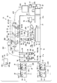
- FIG. 1 is an explanatory diagram schematically showing the configuration of the additive manufacturing apparatus according to the first embodiment.
- FIG. 2 is an explanatory view schematically showing a main part configuration of the layered manufacturing apparatus.
- FIG. 3 is a perspective view showing a configuration of a main part of the layered manufacturing apparatus.
- FIG. 4 is an explanatory view showing an example of manufacturing a layered object using the same layered manufacturing apparatus.
- FIG. 5 is an explanatory diagram illustrating an example of manufacturing a support model using the layered modeling apparatus.
- FIG. 6 is an explanatory view showing an example of manufacturing the layered object.
- FIG. 7 is an explanatory diagram illustrating an example of the configuration of the layered object and the support object.
- FIG. 1 is an explanatory diagram schematically showing the configuration of the additive manufacturing apparatus according to the first embodiment.
- FIG. 2 is an explanatory view schematically showing a main part configuration of the layered manufacturing apparatus.
- FIG. 3 is a perspective view showing a configuration of a main
- FIG. 8 is an explanatory diagram schematically showing the configuration of the additive manufacturing apparatus according to the second embodiment.
- FIG. 9 is an explanatory diagram illustrating an example of manufacturing a support model using the layered modeling apparatus.
- FIG. 10 is an explanatory diagram showing the configuration of the main material and the binding material of the support material used in the layered manufacturing apparatus.
- FIG. 11 is an explanatory diagram illustrating a configuration of a main material and a binding material used in the additive manufacturing apparatus according to the third embodiment.
- FIG. 12 is an explanatory diagram showing the configuration of the main material used in the layered manufacturing apparatus according to the fourth embodiment.
- FIG. 13 is an explanatory diagram illustrating an example of manufacturing a support model using the layered modeling apparatus according to the fifth embodiment and the sixth embodiment.
- the additive manufacturing apparatus of the embodiment includes the nozzle device, the optical system, and a control device.
- the nozzle device is capable of supplying powder to an elephant, and is formed so as to form a layer for modeling a molded object, and a nozzle formed so as to be able to irradiate the object with energy rays.
- a supply device that selectively supplies a powdery support material for forming a support layer capable of forming the layer formed of the material and the modeling material on the upper surface thereof;
- the optical system outputs the energy rays that can melt the modeling material supplied to the object and partially melt the support material supplied to the object to the nozzle.
- the control device is formed so as to control the supply amount of the modeling material and the supply amount of the support material that are driven to the nozzle and supplied to the nozzle, and is formed on the object by the modeling material.
- the layer and the support layer are stacked.
- FIG. 1 is an explanatory diagram schematically illustrating the configuration of the additive manufacturing apparatus 1 according to the first embodiment
- FIG. 2 is a cross-sectional view illustrating the configuration of nozzles 33 and 43 used in the additive manufacturing apparatus 1
- FIG. 4 is an explanatory view showing an example of manufacturing a layered object 100 using the layered manufacturing apparatus 1
- FIG. 5 shows the layered apparatus 1.
- FIG. 6 is an explanatory diagram illustrating an example of manufacturing the layered object 100
- FIG. 7 is an example of the configuration of the layered object 100 and the support object 101. It is explanatory drawing which shows the structure of 110b and the support layer 110c.
- the additive manufacturing apparatus 1 includes a processing tank 11, a stage 12, a moving device 13, a nozzle device 14, an optical device 15, a measuring device 16, a removing device 17, and a control device 18. And.
- the additive manufacturing apparatus 1 can form the additive object 100 having a predetermined shape by laminating a plurality of the forming materials 121 and 122 supplied by the nozzle device 14 as a layer on the object 110 provided on the stage 12. Is formed.
- the layered object 100 is formed in a so-called overhang shape having a protruding portion 100 a that partially projects.
- the layered modeling apparatus 1 causes the object 110 to stack a plurality of support materials 131 supplied by the nozzle device 14 in a layered manner, so that at least the projecting portion 100a below the projecting portion 100a of the layered model 100 is provided.
- projection part 110a is formed in the range provided so that modeling is possible.
- the object 110 is a base 110a for modeling the layered object 100 on its upper surface, a layer 110b that forms part of the layered object 100, or a support layer that forms part of the support object 101. 110c or the like.
- the object 110 is an object to which the modeling materials 121 and 122 and the support material 131 are supplied by the nozzle device 14.
- the modeling materials 121 and 122 are powder metal materials, and a single metal material or a plurality of different metal materials, for example, the first modeling material 121 and the second modeling material 122 are used. In the present embodiment, a configuration for modeling the layered object 100 using the two first modeling materials 121 and the second modeling material 122 will be described.
- the support material 131 is, for example, a powder metal material.
- the processing tank 11 includes a main chamber 21, a sub chamber 22 formed adjacent to the main chamber 21, and a door 23 that can open and close the main chamber 21 and can close the main chamber 21 in an airtight manner. ing.
- the main chamber 21 is formed so that the stage 12, the moving device 13, a part of the nozzle device 14, and the measuring device 16 can be arranged therein.
- the main chamber 21 includes, for example, a supply port 21a through which an inert gas such as nitrogen and argon is supplied, and a discharge port 21b through which the gas in the main chamber 21 is discharged.
- the main chamber 21 is connected to a supply device whose supply port 21a supplies an inert gas.
- the discharge port 21 b is connected to a discharge device that discharges the gas in the main chamber 21.
- the sub chamber 22 is formed so that the main chamber 21 and the space can continue through the door portion 23.
- the layered object 100 processed in the main chamber 21 is conveyed.
- the sub-chamber 22 is, for example, a transfer device 24 such as a transfer device that loads the manufactured layered product 100 and transports it from the main chamber 21 or a transport arm that adsorbs and transports the layered product 100 with a vacuum head or the like. It has. Moreover, the subchamber 22 is equipped with the removal apparatus 17 which removes the support modeling thing 101 from the laminated modeling thing 100 in the inside. The sub chamber 22 is isolated from the main chamber 21 by closing the door portion 23 when the layered object 100 is formed.
- a transfer device 24 such as a transfer device that loads the manufactured layered product 100 and transports it from the main chamber 21 or a transport arm that adsorbs and transports the layered product 100 with a vacuum head or the like. It has.
- the subchamber 22 is equipped with the removal apparatus 17 which removes the support modeling thing 101 from the laminated modeling thing 100 in the inside.
- the sub chamber 22 is isolated from the main chamber 21 by closing the door portion 23 when the layered object 100 is formed.
- the stage 12 is formed so as to be able to support the object 110 at the top thereof.
- the moving device 13 is formed to be able to move the stage 12 in three axial directions.
- the nozzle device 14 can selectively supply a plurality of types of modeling materials 121 and 122 to the object 110 on the stage 12 by a predetermined amount, and emits a laser beam 200 as energy rays for melting the modeling materials 121 and 122. It is made possible.
- the nozzle device 14 includes a first nozzle device 14 a that supplies modeling materials 121 and 122 that model the layered object 100, and a second nozzle device 14 b that supplies support material 131 that supports the layered object 100.
- symbol is attached
- the first nozzle device 14 a includes a first supply device 31 that can supply the first modeling material 121, a second supply device 32 that can supply the second modeling material 122, and the first supply device 31 and the second supply device 32.
- a nozzle 33 connected to the optical device 15 and a supply pipe 34 connecting the first supply device 31 and the nozzle 33 and the second supply device 32 and the nozzle 33 are provided.
- the first modeling material 121 is a powdered metal material.
- the second modeling material 122 is a metal material that is powdery and different from the first modeling material.
- the first supply device 31 includes a tank 31a that stores the first modeling material 121, and a supply unit 31b that supplies the first modeling material 121 from the tank 31a to the nozzle 33 by a predetermined amount.
- the supply means 31b is formed so as to be able to supply the first modeling material 121 in the tank 31a to the nozzle 33 using an inert gas such as nitrogen or argon as a carrier.
- the supply means 31b is formed so that the supply amount of the 1st modeling material 121 to supply and the injection speed (supply speed) of the 1st modeling material 121 injected from the nozzle 33 can be adjusted.
- the second supply device 32 includes a tank 32a that stores the second modeling material 122, and a supply unit 32b that supplies the second modeling material 122 from the tank 32a to the nozzle 33 by a predetermined amount.
- the supply means 32b is formed to be able to supply the second modeling material 122 in the tank 32a to the nozzle 33 using an inert gas such as nitrogen or argon as a carrier, for example.
- the supply means 32b is formed so that the supply amount of the 2nd modeling material 122 to supply and the injection speed (supply speed) of the 2nd modeling material 122 injected from the nozzle 33 can be adjusted.
- the nozzle 33 is connected to the first supply device 31 and the second supply device 32 via a supply pipe 34.
- the nozzle 33 is connected to the optical device 15 via a cable 210 that can pass the laser beam 200.
- the nozzle 33 is formed to be movable with respect to the stage 12.
- the nozzle 33 is provided in the outer shell 36, the injection port 37 that ejects the first modeling material 121 and the second modeling material 122 from the tip, and the optical path that allows the laser light 200 to pass therethrough. Part 38 and an optical lens 39 provided in the light path part 38.
- the nozzle 33 is formed so that the powdered first modeling material 121 and the second modeling material 122 supplied from the first supply device 31 and the second supply device 32 can be mixed.
- the nozzle 33 can mix the powdery 1st modeling material 121 and the 2nd modeling material 122 which were supplied from the 1st supply apparatus 31 and the 2nd supply apparatus 32 in the inside, for example, or the some injection nozzle 37
- the first modeling material 121 and the second modeling material 122 are respectively ejected from the first and second molding materials 122 so that the first modeling material 121 and the second modeling material 122 can be mixed after injection.
- a plurality of injection ports 37 are provided, one part is the first injection port 37 a connected to the first supply device 31, and the other part is connected to the second supply device 32. It demonstrates using the structure which is the 2nd injection nozzle 37b.
- the injection port 37 includes the injection port 37 in which the first modeling material 121 and the second modeling material 122 conveyed by the gas supplied from the first supply device 31 and the second supply device 32. Are formed so as to be inclined with respect to the axis of the outer body 36, more specifically, the optical axis of the emitted laser light 200, so as to intersect at a predetermined distance from the center.
- the light passage portion 38 is provided along the axis of the outer body 36.
- the optical lens 39 is provided in the light path portion 38, for example.
- Two optical lenses 39 are provided so as to convert the laser light 200 from the cable 210 into parallel light and to converge the parallel light.
- the optical lens 39 is configured to converge most at a predetermined position, specifically, at a position where the first modeling material 121 and the second modeling material 122 injected from the injection port 37 intersect.
- the second nozzle device 14 b includes a third supply device 41 that can supply the support material 131, a nozzle 43 connected to the third supply device 41 and the optical device 15, and a supply that connects the third supply device 41 and the nozzle 43.
- a tube 34 is
- the third supply device 41 includes a tank 41a for storing the support material 131, and a supply means 41b for supplying the support material 131 from the tank 41a to the nozzle 43 by a predetermined amount.
- the supply means 41b is formed to be able to supply the support material 131 in the tank 41a to the nozzle 43 using, for example, an inert gas such as nitrogen or argon as a carrier.
- the supply means 41 b is formed so as to be able to adjust the supply amount of the support material 131 to be supplied and the injection speed (supply speed) of the support material 131 injected from the nozzle 43.
- the support material 131 is a powdery metal material, and is composed of a material having a higher melting point than the first modeling material 121 and the second modeling material 122 that model the layered object 100.
- the nozzle 43 is connected to the third supply device 41 via the supply pipe 34.
- the nozzle 43 is connected to the optical device 15 via a cable 210 that can pass the laser beam 200.
- the nozzle 43 is formed to be movable with respect to the stage 12.
- the nozzle 43 is provided in the outer shell 36, a plurality of ejection ports 37 that eject the support material 131 from the tip thereof, a light passage portion 38 that allows the laser light 200 to pass, and a light passage. And an optical lens 39 provided in the section 38.
- the optical device 15 includes a light source 51 and an optical system 52 connected to the light source 51 via a cable 210.
- the light source 51 has a light emitting element and is a supply source of the laser light 200 formed so that the laser light 200 can be emitted from the light emitting element.
- the light source 51 is formed so that the power density of the emitted laser light can be changed.
- the optical system 52 is formed so that the laser beam 200 emitted from the light source 51 can be supplied to the nozzles 33 and 43, and the base 110a, the layer 110b, and the support layer 110c, which are the objects 110, can be irradiated.
- the optical system 52 includes a first lens 61, a second lens 62, a third lens 63, a fourth lens 64, and a galvano scanner 65.
- the first lens 61, the second lens 62, the third lens 63, and the fourth lens 64 are fixed.
- the optical system 52 is an adjustment device capable of moving the first lens 61, the second lens 62, the third lens 63, and the fourth lens 64 in two axial directions, specifically, in a direction orthogonal to or intersecting the optical path. May be provided.
- the first lens 61 is formed so that the laser beam 200 incident through the cable 210 can be converted into parallel light, and the converted laser beam 200 can be incident on the galvano scanner 65.
- the same number of second lenses 62 as the nozzles 33 and 43 are provided. In the present embodiment, three second lenses 62 are provided.
- the second lens 62 is formed so that the laser beam 200 emitted from the galvano scanner 65 is converged and the laser beam 200 can be emitted to the nozzle 33 via the cable 210.
- the third lens 63 is formed so that the laser beam 200 emitted from the galvano scanner 65 is converged and the laser beam 200 can be irradiated on the object 110.
- the fourth lens 64 is formed so that the laser beam 200 emitted from the galvano scanner 65 is converged and the laser beam 200 can be irradiated onto the object 110.
- the galvano scanner 65 is formed so that the parallel light converted by the first lens 61 can be divided into a second lens 62, a third lens 63, and a fourth lens 64.
- the galvano scanner 65 includes a first galvanometer mirror 67, a second galvanometer mirror 68, and a branch mirror 69.
- Each of the galvanometer mirrors 67 and 68 is formed so that the inclination angle can be varied and the laser beam 200 can be divided.
- the branch mirror 69 is formed so that the laser beam 200 can be split.
- the first galvanometer mirror 67 allows part of the laser beam 200 that has passed through the first lens 61 to pass therethrough so as to emit the laser beam 200 to the second galvanometer mirror 68 and reflect the other part of the laser beam 200. Then, the laser beam 200 is emitted to the fourth lens 64.
- the first galvanometer mirror 67 is formed such that the irradiation position of the laser beam 200 that has passed through the fourth lens 64 can be adjusted by the inclination angle.
- the second galvanometer mirror 68 emits a part of the laser light 200 to the branch mirror 69 and reflects the other part of the laser light 200 to the third lens 63.
- the second galvanometer mirror 68 is formed such that the irradiation position of the laser beam 200 that has passed through the third lens 63 can be adjusted by the inclination angle.
- the branch mirror 69 emits the laser beam 200 to the second lens 62.
- the branch mirror 69 has, for example, a configuration that reflects the laser light 200 and emits it to each second lens 62, or a configuration that selectively emits the laser light 200 to any one of the second lenses 62.
- Such an optical system 52 includes a first modeling material 121 (123) and a second modeling material 122 (123) supplied to the object 110 by the first galvanometer mirror 67, the second galvanometer mirror 68, and the third lens 63.
- the support material 131 is heated to form the layer 110b or the support layer 110c, and the melting device 55 that performs an annealing process is configured.
- the melting device 55 melts the first modeling material 121 and the second modeling material 122 supplied from the nozzle 33 on the base 110a or on the formed layer 110b by the laser beam 200 to form the layer 110b. In addition, the melting device 55 melts a part of the support material 131 supplied from the nozzle 43 on the base 110a, the layer 110b, or the support layer 110c with the laser beam 200 to form the support layer 110c.
- the optical system 52 includes unnecessary portions formed on the base 110a, the layer 110b, and the support layer 110c by the first modeling material 121, the second modeling material 122, and the support material 131, and the first galvanometer mirror 67 and the fourth lens.
- a trimming device 56 is configured to be removed by the laser beam 200 supplied by 64.
- the trimming device 56 is unnecessary when the first modeling material 121, the second modeling material 122, and the support material 131 are supplied from the nozzles 33 and 43, and is generated when the layer 110b and the support layer 110c are formed.
- the part is formed to be removable.
- the unnecessary part is a part different from the predetermined shape of the layered object 100 and the predetermined shape of the support object 101.
- the trimming device 56 is formed so as to emit a laser beam 200 having a power density capable of removing the portion.
- the measuring device 16 measures the shapes of the layer 110b and the support layer 110c, which are the shapes of the solidified materials 121, 122, and 131 on the base 110a, and the shapes of the formed layered object 100 and the support object 101. It is possible to be formed.
- the measuring device 16 is formed so as to be able to transmit the measured shape information to the control device 18.
- the measurement device 16 includes a camera 71 and an image processing device 72 that performs image processing based on information measured by the camera 71.
- the measuring device 16 is formed so as to be able to measure the shapes of the layer 110b, the support layer 110c, the layered object 100, and the support object 101 by, for example, an interference method or a light cutting method.
- the removal device 17 is formed so as to be able to mechanically remove the support molded article 101 by shot blasting, for example.
- the structure which removes the support molded article 101 by cutting etc. may be sufficient as the removal apparatus 17.
- the control device 18 includes a signal line 220 to the moving device 13, the removing device 17, the transport device 24, the first supply device 31, the second supply device 32, the third supply device 41, the light source 51, the galvano scanner 65, and the image processing device 72. It is electrically connected via.
- the control device 18 is configured to be able to move the stage 12 in three axial directions by controlling the moving device 13.
- the control device 18 can transport the shaped layered object 100 to the sub chamber 22 by controlling the conveying device 24, and can control the removal device 17 to control the layered object 100 conveyed to the sub chamber 22. It is formed so that the support modeling thing 101 can be removed from.
- the control device 18 is configured to be able to adjust the supply of the first modeling material 121, the supply amount and the supply speed of the first modeling material 121 by controlling the supply means 31b.
- the control device 18 is configured to be able to adjust the supply of the second modeling material 122, the supply amount and the supply speed of the second modeling material 122 by controlling the supply means 32b.
- the control device 18 is configured to be able to adjust the supply of the support material 131, the supply amount of the support material 131, and the supply speed by controlling the supply means 41b.
- the control device 18 is formed so as to be able to adjust the power density of the laser light 200 emitted from the light source 51 by controlling the light source 51.
- the control device 18 is configured to be able to adjust the tilt angles of the first galvanometer mirror 67, the second galvanometer mirror 68, and the branch mirror 69 by controlling the galvanometer scanner 65.
- the control apparatus 18 is formed so that the nozzle 33 can be moved.
- the control device 18 includes a storage unit 18a.
- the shape of the layered object 100 to be modeled and the shape of the support model 101 are stored as threshold values.
- the ratio of the modeling materials 121 and 122 in each layer 110b of the layered object 100 to be modeled is stored in the storage unit 18a.
- the support model 101 is, for example, In the lower layer of the overhang portion 100a, the overhang direction of the overhang portion 100a, in other words, the same shape as the surface direction of the layer 110b forming the layered object 100, or the shape of the overhang portion 100a in the surface direction. Is also set to a large shape.
- the support model 101 may have a shape smaller than the shape in the surface direction of the overhang 100a as long as the overhang 100a can be modeled.
- the control device 18 has the following functions (1) to (4).
- the function (1) is based on the ratio of the first modeling material 121 and the second modeling material 122 in each layer 110b of the preset layered object 100 stored in the storage unit 18a. 121 and the second modeling material 122 are selectively injected to form the layer 110b.
- the nozzle 33 is moved with respect to the object 110, and the supply means 31b and 32b of the first supply device 31 and the second supply device 32 are used. To control. Thereby, the ratio of the 1st modeling material 121 set to the said layer 110b and the 2nd modeling material 122 is adjusted, and the 1st modeling material is supplied from the nozzle 33 with respect to the target object 110 by the predetermined supply amount and supply speed. 121 and the second modeling material 122 are injected.
- the laser beam 200 is emitted from the nozzle 33, and the target 110 and the jetted first modeling material 121 and the second modeling material 122 are irradiated with the laser beam 200, and the first modeling material 121 and the second modeling material 122 are irradiated. Melt. Further, for example, the assembly of the layer 110b on the object 110 is further irradiated with the laser light 200, and the layer 110b is remelted to perform the annealing treatment.
- the gradient material is formed by changing the ratio of the first modeling material 121 and the second modeling material 122.
- the layer 110b is laminated to form a portion formed only by the first modeling material 121.
- the ratio of the 1st modeling material 121 and the 2nd modeling material 122 is changed gradually until the site
- the first modeling material 121 and the second modeling material 122 are changed by changing the ratio of the modeling material of the layer 110b so that the ratio of the first modeling material and the second modeling material is halved at the intermediate position of the part formed by Supply.
- the first modeling material 121 and the second modeling material 122 are irradiated with a laser beam 200 having a power density at which the first modeling material 121 and the second modeling material 122 are melted. 122 is melted to form each layer 110b.
- the function (1) is a function of forming each layer 110b of the preset layered object 100 on the object 110 so that the ratio of the first modeling material 121 and the second modeling material 122 can be varied.
- the function (2) is a function of selectively injecting the support material 131 from the nozzle 43 based on each support layer 110c of the preset support model 101 stored in the storage unit 18a to form the support layer 110c. It is.
- the support layer of the support model 101 formed at the same level as the layer 110b of the layered model 100 formed by the function (1).
- the nozzle 43 is moved relative to the object 110 within a range where 110c is formed, and the supply means 41b of the third supply device 41 is controlled.
- the support material 131 is ejected from the nozzle 43 to the object 110 at a predetermined supply amount and supply speed.
- a laser beam 200 having a power density at which a part of the support material 131 is melted is emitted from the nozzle 43 and irradiated to the support material 131 ejected from the nozzle 43. Accordingly, the support material 131 is partially melted without melting the support material 131 completely, thereby forming the support layer 110c in which the support materials 131 are partially bonded to each other. Note that the support layer 110c may be formed before the layer 110b of the same layer of the layered object 100 is formed by the function (1).
- the function (2) is a function of forming each support layer 110c of the support model 101 set in advance on the object 110.
- the function (3) includes a layer 110b formed by the first modeling material 121, the second modeling material 122, and the support material 131 ejected from the nozzles 33 and 43 on the base 110a, the layered object 100, the support layer 110c, or This is a function for determining whether or not the layer 110b and the support layer 110c have a predetermined shape by measuring the shape of the support modeling object 101 with the measuring device 16 and comparing it with the threshold value of the storage unit 18a.
- each material 121, 122, 131 is ejected from the nozzles 33, 43 using a gas toward the base 110a, and each material 121, 122, 131 is melted by the laser beam 200. For this reason, when material 121,122,131 is supplied on the target object 110, a part of the material 121,122,131 may scatter and a part different from a predetermined shape may be formed. . In addition, since the first modeling material 121 and the second modeling material 122 are melted, the melted first modeling material 121 and the second modeling material 122 flow, and the first modeling material 121 and the second modeling material 122 flow in a position different from the predetermined shape. The modeling material 121 and the second modeling material 122 may flow.
- the function (3) compares the shape measured by the measuring device 16 with the threshold value stored in the storage unit 18a, and determines whether or not the formed layer 110b and the support layer 110c have a predetermined shape. It is a function to do. In other words, the function (3) determines whether or not the material 121, 122, 131 is attached to a portion different from the predetermined shape of the layered object 100 and has a portion protruding from the predetermined shape (threshold). It is a function. The determination based on the function (3) is preferably performed every time the layer 110b and the support layer 110c are formed in the function (1) and the function (2), respectively.
- the function (4) removes the materials 121, 122, 131 of parts different from the predetermined shape measured in the function (3), so that the materials 121, 122, 131 supplied from the nozzles 33, 43 are removed.
- This is a function for trimming to a predetermined shape. Specifically, when it is determined in the function (3) that the materials 121, 122, 131 are supplied to parts different from the predetermined shape, the light is emitted from the fourth lens 64 via the first galvanometer mirror 67.
- the light source 51 is controlled so that the laser beam 200 thus obtained has a power density capable of evaporating the materials 121, 122, and 131.
- the first galvanometer mirror 67 is controlled to irradiate the portion with the laser beam 200 to evaporate the materials 121, 122, and 131.
- the function (4) is a function of trimming the formed layer 110b and the support layer 110c into a predetermined shape.
- the control device 18 controls the first supply device 31 and the second supply device 32 so that predetermined amounts of the first modeling material 121 and the second modeling material 122 are nozzles. It is sprayed from 33 to a predetermined range of the object 110 and melted (sprayed).
- the first supply device 31 and the second supply device 32 are controlled by the control device 18, and the first modeling material 121 and / or the injection material 37 so as to become a predetermined modeling material of the layer 110 b to be formed.
- the second modeling material 121 is sprayed at a predetermined ratio.
- the injected modeling material 121,122 is melted by irradiating the laser beam 200.
- a molten pool is formed in a range where the layer 110b on the base 110a is formed, and the first modeling material 121 and the second modeling material 122 supplied at a predetermined ratio are melted in the melting pool.
- the molten modeling material 123 constituted thereby is solidified by, for example, natural cooling, whereby the layer 110b is formed.
- the molten pool is a molten portion formed by the first modeling material 121, the second modeling material 122, and the object 110 that are melted by irradiation with the laser beam 200.
- the melting device 55 is controlled to irradiate the set of layers 110b with the laser beam 200, and the layer 110b made of the modeling material 123 is remelted to perform an annealing process.
- the measuring device 16 measures the layer 110b (the modeling material 123) on the base 110a subjected to the annealing treatment.
- the control device 18 compares the shape of the layer 110b on the base 110a measured by the measurement device 16 with the threshold value stored in the storage unit 18a.
- the control device 18 determines that the shape is abnormal.
- the control device 18 controls the trimming device 56 to irradiate the laser beam 200 to a part different from the predetermined shape or the attached modeling material 123a to evaporate unnecessary modeling material 123. In this way, the control device 18 removes the unnecessary modeling material 123 by irradiating the laser beam 200 to a portion where the shape of the layer 110b measured by the measurement device 16 is different from the predetermined shape, so that the layer 110b has a predetermined shape. Trimming is performed.
- the control device 18 When the modeling material 123 on the base 110a is formed on the layer 110b having a predetermined shape, or when the trimming of the layer 110b is completed, the control device 18 next forms the support layer 110c. Specifically, as shown in FIGS. 2 and 5, the control device 18 controls the third supply device 41 to inject a predetermined amount of the support material 131 from the nozzle 43 into a predetermined range of the object 110. Then, a part of the support material 131 is melted by irradiating the laser beam 200 so that the support materials 131 are bonded to each other. As a result, the support materials 131 are welded together, and a support layer 110c partially bonded to each other is formed.
- the formed support layer 110c (support material 131) is measured by the measuring device 16.
- the control device 18 compares the shape of the support layer 110c on the base 110a measured by the measurement device 16 with the threshold value stored in the storage unit 18a.
- the control device 18 controls the trimming device 56. Then, the laser beam 200 is irradiated to a portion different from the predetermined shape or the attached support material 131 to evaporate the unnecessary support material 131. As described above, the control device 18 removes the unnecessary support material 131 by irradiating the laser beam 200 to a portion where the shape of the support layer 110c measured by the measurement device 16 is different from the predetermined shape, so that the support layer 110c has a predetermined shape. Trimming is performed to obtain a shape.
- the control device 18 controls the first supply device 31 and the second supply device 32 again to form a new layer 110b on the formed layer 110b or the support layer 110c.
- the support layer 110c is formed in the same hierarchy as necessary.
- the control device 18 repeatedly forms the layer 110b and the support layer 110c, and stacks the layer 110b and the support layer 110c.
- the control device 18 repeatedly laminates these layers 110b and the support layer 110c to form the layered object 100 in which the projecting portion 100a is supported by the support object 101 as shown in FIG.
- the control device 18 transports the layered object 100 to the sub chamber 22 by the transport device 24.
- the control device 18 drives the removal device 17 to perform shot blasting on the layered object 100. Since the support model 101 has a configuration in which a part of the support material 131 is coupled, the joint part coupled to each other is broken by shot blasting, and the support model 101 is removed from the layered model 100.
- the layered object 100 is formed by these steps.
- the layered manufacturing apparatus 1 configured in this way can be supported by the support model 101 even if the modeled model 100 to be modeled has the projecting portion 100a.
- the layer 110b can be formed on the formed support layer 110c. For this reason, even if it is the structure which models the layered object 100 by what is called a directional energy deposition method which inject
- the support molded article 101 is configured to perform so-called pre-sintering in which only part of the support material 131 is melted and bonded to each other without being completely melted, and thus is mechanically removed by shot blasting or the like. It becomes possible.
- the support material 131 is a material having a melting point higher than those of the first modeling material 121 and the second modeling material 122 that model the layered object 100, so that the first modeling material 121 and the second modeling material 122 are layered.
- the support material 131 can be prevented from melting in the first modeling material 121 and the second modeling material 122.
- the layered object 100 having a protruding portion 100a which is an overhang shape in which a part protrudes. Can be shaped. Moreover, it becomes possible to remove easily the support molded article 101 for forming the overhang
- FIG. 8 is an explanatory view schematically showing the configuration of the additive manufacturing apparatus 1A according to the second embodiment
- FIG. 9 is an explanatory view showing an example of manufacturing the support object 101 using the additive manufacturing apparatus 1A
- FIG. 11 shows the relationship between the main material 132 of the support material 131 and the binding material 133 that form the support layer 110 c, and the laser beam 200 as a part of the configuration of the support model 101. It is explanatory drawing.
- the additive manufacturing apparatus 1 ⁇ / b> A includes a processing tank 11, a stage 12, a moving device 13, a nozzle device 14 ⁇ / b> A, an optical device 15, a measuring device 16, and a control device 18. Yes.
- the additive manufacturing apparatus 1A can form the additive object 100 having a predetermined shape by laminating a plurality of the forming materials 121 and 122 supplied by the nozzle device 14A as a layer on the object 110 provided on the stage 12. Is formed.
- the layered object 100 is formed in a so-called overhang shape having a projecting portion 100a that partially projects.
- the additive manufacturing apparatus 1 supports the object 110 to support the projecting portion 100a of the additive manufacturing object 100 by laminating a plurality of support materials 131 supplied by the nozzle device 14A as a layer. Is formed so that it can be shaped.
- the support material 131 includes a main material 132 and a bind material 133.
- the main material 132 is a powdery metal material.
- the binding material 133 is a powder metal material and is a binder that binds the main material 132.
- the main material 132 and the binding material 133 constitute the support material 131 (support layer 110c).
- the nozzle device 14A is formed so that a predetermined amount of a plurality of types of materials can be selectively supplied to the object 110 on the stage 12 and the laser beam 200 can be emitted.
- the nozzle device 14A includes a first nozzle device 14a that supplies a modeling material for modeling the layered object 100, and a second nozzle device 14c that supplies a support material 131 that supports the layered object 100. I have.
- the second nozzle device 14 c includes a third supply device 41 capable of supplying the main material 132, a fourth supply device 42 capable of supplying the binding material 133, the third supply device 41, the fourth supply device 42, and the optical device 15. And a supply pipe 34 for connecting the third supply device 41 and the nozzle 43 to each other. That is, the second nozzle device 14 c is configured by providing a fourth supply device 42 that can supply the binding material 133 to the nozzle 43 by the fourth supply device 42 in addition to the second nozzle device 14 b described above.
- the fourth supply device 42 includes a tank 42a for storing the bind material 133, and a supply means 42b for supplying the bind material 133 from the tank 42a to the nozzle 43 by a predetermined amount.
- the supply means 42 b is formed so as to be able to supply the bind material 133 in the tank 42 a to the nozzle 43 using an inert gas such as nitrogen or argon as a carrier.
- the supply means 42 b is formed so as to be able to adjust the supply amount of the bind material 133 to be supplied and the injection speed (supply speed) of the bind material 133 injected from the nozzle 43.
- the main material 132 is a powder metal material and is made of a material having a higher melting point than the first modeling material 121 and the second modeling material 122 that model the layered object 100.
- the binding material 133 is, for example, the same metal material as the main material 132 or a material having a melting point lower than that of the main material 132, and the particle size thereof is sufficiently smaller than the particle size of the main material 132. Further, as shown in FIGS. 9 and 10, the main material 132 and the binding material 133 are formed with a diameter smaller than the diameter of the irradiated laser beam 200.
- AlSi12 (A4047, melting point 580 ° C.) is used as the modeling material 123 that forms the layered object 100 using the first modeling material 121 and the second modeling material
- Al 50 ⁇ m in diameter
- A1050, melting point 660 ° C.) and AlSi12 (A4047, melting point 580 ° C.) having a particle diameter of 20 ⁇ m can be used as the binding material 133.
- the volume mixing ratio of the binding material 133 with respect to the main material 132 is set to 7.1% or less.
- flux such as KF and CeF may be added in order to remove oxide films formed on the surfaces of the main material 132 and the binding material 133.
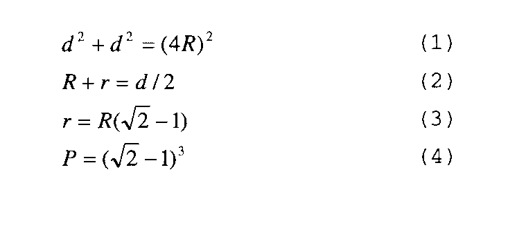
- the particle size and volume mixing ratio of the main material 132 and the binding material 133 can be obtained from the following equation, for example.
- the materials 132 and 133 are close-packed in the support layer 110c, the materials 132 and 133 are considered to be arranged in a face-centered cubic lattice.
- the radius of the main material 132 is R
- the radius of the binding material 133 is r
- the lattice constant is d
- the relationship between the radii R and r of the main material 132 and the binding material 133 is expressed by the following equations (1) and (2)
- the volume mixing ratio P with respect to the main material 132 is Equation (4).
- the particle size of the binding material 133 is 20 ⁇ m.
- the volume mixing ratio of the main material 132 and the binding material 133 is 7.1% or less.
- the particle sizes and volume mixing ratios of the main material 132 and the binding material 133 are not limited to these, and can be set as appropriate as long as the support layer 110c can be formed.
- the nozzle 43 can mix, for example, the powdery main material 132 and the binding material 133 supplied from the third supply device 41 and the fourth supply device 42 in the same manner as the nozzle 33, or a plurality of injections
- the main material 132 and the binding material 133 are respectively ejected from the mouth 37, and the main material 132 and the binding material 133 are formed so as to be mixed after the ejection.
- the nozzle 43 is connected to a gas supply means for supplying a shielding gas such as an inert gas, and is formed so as to be able to supply the shielding gas from the light passage portion 38 to the irradiation portion of the laser beam 200.
- the control device 18 includes a moving device 13, a removing device 17, a conveying device 24, a first supply device 31, a second supply device 32, a third supply device 41, a fourth supply device 42, a light source 51, a galvano scanner 65, and image processing. It is electrically connected to the device 72 via a signal line 220.
- the control device 18 is configured to be able to move the stage 12 in three axial directions by controlling the moving device 13.
- the control device 18 is formed so as to be able to convey the shaped layered object 100 to the sub chamber 22 by controlling the conveying device 24.
- the control device 18 is configured to be able to adjust the supply of the first modeling material 121, the supply amount and the supply speed of the first modeling material 121 by controlling the supply means 31b.
- the control device 18 is configured to be able to adjust the supply of the second modeling material 122, the supply amount and the supply speed of the second modeling material 122 by controlling the supply means 32b.
- the control device 18 is configured to be able to adjust the supply of the main material 132, the supply amount of the main material 132, and the supply speed by controlling the supply means 41b.
- the control device 18 is configured to be able to adjust the supply of the bind material 133, the supply amount of the bind material 133, and the supply speed by controlling the supply means 42b.
- the control device 18 is formed so as to be able to adjust the power density of the laser light 200 emitted from the light source 51 by controlling the light source 51.
- the control device 18 is configured to be able to adjust the tilt angles of the first galvanometer mirror 67, the second galvanometer mirror 68, and the branch mirror 69 by controlling the galvanometer scanner 65.
- the control apparatus 18 is formed so that the nozzle 33 can be moved.
- the control device 18 includes a storage unit 18a.
- the shape of the layered object 100 to be modeled and the shape of the support model 101 are stored as threshold values.
- the storage unit 18a stores the ratio of the modeling materials 121 and 122 in each layer 110b of the layered object 100 to be modeled.
- the ratio of the main material 132 and the binding material 133 in the support modeling object 101 to be modeled is stored in the storage unit 18a.
- the control device 18 has the functions (1), (3), and (4) described above, and the following function (5).
- Function (5) selectively selects the main material 132 and the binding material 133 from the nozzle 43 based on the support layers 110c of the support molded article 101 stored in the storage unit 18a and the ratio of the main material 132 and the binding material 133. It is a function to inject.
- the support layer of the support model 101 formed at the same level as the layer 110b of the layered model 100 formed by the function (1).
- the nozzle 43 is moved with respect to the object 110 within a range in which 110c is formed, and the supply means 41b and 42b of the third supply device 41 and the fourth supply device 42 are controlled. Thereby, the main material 132 and the binding material 133 are injected from the nozzle 43 at a predetermined supply amount and supply speed to the object 110.
- a laser beam 200 having a power density at which the binding material 133 is melted is emitted from the nozzle 43 and irradiated onto the binding material 133 that is injected onto the object 110. Even though the binding material 133 has the same melting point as the melting point of the main material 132, the binding material 133 is formed with a smaller diameter than the main material 132. Therefore, the binding material 133 is ahead of the main material 132. To melt.
- the bind material 133 is selectively melted, so that only the bind material 133 is melted in a state where the main material 132 is not melted, and the support layer 110c in which the main material 132 is bonded by the bind material 133 is formed. Is done.
- the structure which forms the support layer 110c before forming the layer 110b of the same hierarchy of the layered object 100 by function (1) may be sufficient.
- the function (5) is a function for forming each support layer 110c of the support model 101 set in advance on the object 110.
- the layered manufacturing apparatus 1A configured as described above has a predetermined shape by functions (1), (3) to (5), similarly to the method for manufacturing the layered object 100 using the layered manufacturing apparatus 1 described above.
- the layered object 100 in which the projecting portion 100a is supported by the support object 101 is formed.
- the layered manufacturing apparatus 1 configured as described above can be supported by the support modeled object 101 even if the layered model 100 to be modeled has the projecting portion 100a, similarly to the layered model manufacturing apparatus 1 described above. It becomes.
- the layer 110b can be formed on the formed support layer 110c. For this reason, even if it is the structure which models the laminate modeling thing 100 by what is called a directional energy deposition method which inject
- the support molded object 101 is configured to bind the main material 132 using the binding material 133 having a particle diameter smaller than that of the main material 132, it can be mechanically removed by shot blasting or the like.
- the modeled object 101 can be easily removed.
- the main material 132 is a material having a higher melting point than the first modeling material 121 and the second modeling material 122 for modeling the layered object 100, so that the first modeling material 121 and the second modeling material 122 are layered.
- the main material 132 can be prevented from melting in the first modeling material 121 and the second modeling material 122.
- the method for manufacturing the layered object 100 using the layered object modeling apparatus 1A it is possible to form the layered object 100 having a shape having the overhanging portion 100a that partially projects. It becomes.
- the support modeling thing 101 is the structure by which the main material 132 is couple
- the additive manufacturing apparatus 1A according to the third embodiment has the same configuration as the additive manufacturing apparatus 1A according to the second embodiment described above, and the binding material 133 of the support material 131 that forms the support object 101. Only the configuration is different.
- the binding material 133 is formed of a material having a melting point lower than that of the main material 132.
- the binding material 133 may be substantially the same as the particle size of the main material 132 or may be smaller than the particle size of the main material 132.
- FIG. A description will be given by using an example in which the particle diameter of the material 132 is substantially the same. That is, the support layer 110c is made of the support material 131 (the main material 132 and the bind material 133) having different melting points.
- pure aluminum (melting point 660 ° C.) is used for the main material 132
- an AlSi alloy (Si 12%, melting point 580 ° C.) is used for the binding material 133.
- the bind material 133 is ahead of the main material 132 when the support layer 110 c is formed.
- the main material 132 is bonded by the binding material 133 by being melted.
- projection part 100a of the laminated modeling object 100 is easily removed with the removal apparatus 17 similarly to the support modeling object 101 of 2nd Embodiment mentioned above. It becomes possible.
- the overhanging part 100a is provided as in the first and second embodiments described above.
- the layered object 100 can be formed, and the support object 101 can be easily removed.
- the additive manufacturing apparatus 1 according to the fourth embodiment has the same configuration as the additive manufacturing apparatus 1 according to the first embodiment described above, and only the support material 131 that forms the support object 101 is different. It is.
- the support material 131 is a powder metal material and has a higher melting point than the first modeling material 121 and the second modeling material 122 that model the layered object 100.
- a bind layer 131a as a binder is formed on the surface thereof.
- the bind layer 131a is made of a material having a melting point lower than that of the support material 131.
- the support material 131 is formed of copper (melting point: 1085 ° C.)
- the bind layer 131a is formed of a CuP alloy (melting point: about 800 ° C.).
- the support layer 131 is bound by the melt of the bind layer 131a before the support material 131. Combined by layer 131a. For this reason, the support modeling object 101 formed in order to support the overhang
- the overhang part 100a is provided as in the first to third embodiments described above.
- the layered object 100 can be formed, and the support object 101 can be easily removed.
- the additive manufacturing apparatus 1 according to the fifth embodiment has the same configuration as the additive manufacturing apparatus 1 according to the first embodiment described above, and the support material 131 that forms the removal apparatus 17 and the support object 101. Are different configurations.
- the removal device 17 is formed so as to be able to remove the support molded article 101 by an etching process using an etching solution 17a.
- the etching solution 17a used in the removing device 17 the support material 131 can be dissolved, and the modeling materials 121 and 122 forming the layered object 100 have non-dissolving characteristics.
- the support material 131 is composed of a powdered metal material having a dissolution characteristic that is dissolved by the etching solution 17a used in the removing device 17.
- the support material 131 is preferably formed with a higher melting point than the modeling materials 121 and 122.
- a material based on iron is used for the support material 131, and an etching solution 17 a that dissolves the support material 131 is used for the removing device 17.
- a material based on copper is used for the support material 131, and an etching solution 17 a that dissolves the support material 131 is used for the removing device 17.
- the support modeling object 101 formed by the etching process using the removing device 17 is dissolved and removed, thereby removing the support modeling.
- the object 101 can be easily removed.
- the overhang part 100a is provided as in the first to fourth embodiments.
- the layered object 100 can be formed, and the support object 101 can be easily removed.
- the additive manufacturing apparatus 1 according to the sixth embodiment has the same configuration as the additive manufacturing apparatus 1A according to the second embodiment described above, and the support material 131 that forms the removal apparatus 17 and the support object 101.
- the main material 132 and the binding material 133 are different in structure.
- the removal device 17 is formed so that the binding material 133 can be dissolved by an etching process using an etching solution 17a.
- the etching solution 17a used in the removing device 17 can dissolve the binding material 133, and the modeling materials 121 and 122 and the main material 132 forming the layered object 100 have non-dissolving characteristics. Used.
- the main material 132 is a powdery material having a melting point higher than that of the modeling materials 121 and 122, and is composed of a material that is insoluble in the etching solution 17a.
- the main material 132 is made of ceramic.
- the binding material 133 is made of a powdered metal material having a melting point lower than that of the main material 132.
- the binding material 133 is formed to have a particle size smaller than that of the main material 132.
- the binding material 133 has a dissolution characteristic that dissolves in the etching solution 17a.
- alumina Al 2 O 3 , melting point 2100 ° C.
- Al 12 Si melting point: 600 ° C.
- an etching solution 17 a that dissolves the binding material 133 is used for the removing device 17.
- the main material 132 is bonded by the etching process using the removing device 17.
- the support molded article 101 can be removed. Thereby, it becomes possible to remove the support modeling object 101 easily.
- the layered manufacturing apparatus 1 may have a configuration including a recovery device for the main material 132.
- the overhang part 100a is provided, as in the first to fifth embodiments described above.
- the layered object 100 can be formed, and the support object 101 can be easily removed. Further, according to the method for manufacturing the layered object 100, the main material 132 constituting the support material 131 can be reused.
- the manufacturing method of the additive manufacturing apparatus 1, 1 ⁇ / b> A and the additive manufacturing object 100 according to the present embodiment is not limited to the configuration described above.
- the additive manufacturing apparatus 1 or 1A has described the structure in which the additive manufacturing object 100 is formed using the first forming material 121 and the second forming material 122.
- the additive manufacturing object 100 is formed of a single material.
- the structure to model may be sufficient.
- the layered modeling apparatus 1 or 1 ⁇ / b> A has described the configuration in which the first modeling material 121 and the second modeling material 122 are supplied to one nozzle 33, but the configuration is not limited thereto.
- the first modeling material 121 and the second modeling material 122 may be supplied, and the first modeling material 121 and the second modeling material 122 may be mixed and melted on the object 110.
- the layered manufacturing apparatus 1A has been described with the configuration including the third supply device 41 and the fourth supply device 42 in order to supply the main material 132 and the binding material 133, but the present invention is not limited thereto.
- the configuration may be such that only the third supply device 41 is provided, the main material 132 and the bind material 133 are accommodated in the same tank 41a, and the main material 132 and the bind material 133 are supplied to the nozzle 43 by the supply means 41b.
- the main material 132 and the binding material 133 may be supplied using the nozzle 33 that supplies the modeling materials 121 and 122.
- the removal device 17 is configured to mechanically remove the support model 101 from the layered model 100 by shot blasting, cutting, or the like, or chemically support modeled by etching using an etching solution.
- the structure which removes the thing 101 from the laminate-molded article 100 was demonstrated, it is not limited to this.
- the removal device 17 heats the support modeling object 101 at a temperature at which the binding material 133 is made lower in temperature than the modeling materials 121 and 122 and the main material 132 and only the binding material 133 is melted, so that the layered modeling is thermally performed.
- the structure which removes the support modeling thing 101 from the thing 100 may be sufficient.
- the additive manufacturing apparatus 1, 1 ⁇ / b> A includes the main chamber 21 and the sub chamber 22, and the configuration including the removing device 17 in the sub chamber 22 is not limited thereto. May be arranged at a position away from the sub chamber 22.
- the configuration in which the object 110, the modeling materials 121 and 122, a part of the support material 131, the binding material 133 or the binding layer 131a are melted by irradiating the laser beam 200 has been described. It is not limited to. If the object 110 and the modeling materials 121 and 122, a part of the support material 131, the binding material 133, or the binding layer 131a can be melted, other energy rays, for example, an electron beam, radiation, etc. It is also possible to use a structure that melts at
Landscapes
- Engineering & Computer Science (AREA)
- Chemical & Material Sciences (AREA)
- Manufacturing & Machinery (AREA)
- Materials Engineering (AREA)
- Physics & Mathematics (AREA)
- Optics & Photonics (AREA)
- Mechanical Engineering (AREA)
- Plasma & Fusion (AREA)
- Analytical Chemistry (AREA)
- Automation & Control Theory (AREA)
- Powder Metallurgy (AREA)
Abstract
Description
以下、第1の実施形態に係る積層造形装置1及び積層造形物100の製造方法を、図1乃至図7を用いて説明する。
図1は第1の実施形態に係る積層造形装置1の構成を模式的に示す説明図、図2は積層造形装置1に用いられるノズル33,43の構成を示す断面図、図3は積層造形装置1に用いられる光学装置15のガルバノスキャナ65の構成を示す斜視図、図4は積層造形装置1を用いた積層造形物100の製造の一例を示す説明図、図5は積層造形装置1を用いたサポート造形物101の製造の一例を示す説明図、図6は積層造形物100の製造の一例を示す説明図、図7は積層造形物100及びサポート造形物101の構成の一例として、層110b及びサポート層110cの構成を示す説明図である。
機能(1)は、記憶部18aに記憶された、予め設定された積層造形物100の各層110bにおける第1造形材料121及び第2造形材料122の比率に基づいて、ノズル33から第1造形材料121及び第2造形材料122を選択的に噴射し、層110bを形成する機能である。
まず、図2及び図4に示すように、制御装置18は、第1供給装置31及び第2供給装置32を制御して所定の量の第1造形材料121及び第2造形材料122を、ノズル33から対象物110の所定の範囲に噴射して溶融する(溶射する)。具体的には、制御装置18により第1供給装置31及び第2供給装置32を制御し、形成を行う層110bの所定の造形材料となるように、噴射口37から第1造形材料121及び/又は第2造形材料121を所定の比率で噴射させる。また、レーザ光200を照射して、噴射した造形材料121,122を溶融させる。
次に、第2の実施形態に係る積層造形装置1A及び積層造形物100の製造方法を、図8乃至図10を用いて説明する。
図8は第2の実施形態に係る積層造形装置1Aの構成を模式的に示す説明図、図9は積層造形装置1Aを用いたサポート造形物101の製造の一例を示す説明図、図10はサポート造形物101の構成の一部として、サポート層110cの構成を示す説明図、図11はサポート層110cを形成するサポート材料131の主材料132及びバインド材料133とレーザ光200との関係を示す説明図である。なお、第2の実施形態に係る積層造形装置1Aのうち、上述した第1の実施形態に係る積層造形装置1と同様の構成には同一符号を付し、その詳細な説明は省略する。
機能(5)は、記憶部18aに記憶されたサポート造形物101の各サポート層110c並びに主材料132及びバインド材料133の比率に基づいて、ノズル43から主材料132及びバインド材料133を選択的に噴射する機能である。
次に、第3の実施形態に係る積層造形装置1Aを用いた積層造形物100の製造方法について、図11を用いて以下説明する。なお、第3の実施形態に係る積層造形装置1Aは、上述した第2の実施形態に係る積層造形装置1Aと同一の構成であって、サポート造形物101を形成するサポート材料131のバインド材料133のみが異なる構成である。
次に、第4の実施形態に係る積層造形装置1を用いた積層造形物100の製造方法について、以下説明する。なお、第4の実施形態に係る積層造形装置1は、上述した第1の実施形態に係る積層造形装置1と同一の構成であって、サポート造形物101を形成するサポート材料131のみが異なる構成である。
次に、第5の実施形態に係る積層造形装置1を用いた積層造形物100の製造方法について、図13以下説明する。なお、第5の実施形態に係る積層造形装置1は、上述した第1の実施形態に係る積層造形装置1と同一の構成であって、除去装置17及びサポート造形物101を形成するサポート材料131が異なる構成である。
次に、第6の実施形態に係る積層造形装置1Aを用いた積層造形物100の製造方法について、図13を用いて以下説明する。なお、第6の実施形態に係る積層造形装置1は、上述した第2の実施形態に係る積層造形装置1Aと同一の構成であって、除去装置17、サポート造形物101を形成するサポート材料131の主材料132及びバインド材料133が異なる構成である。
Claims (17)
- 対象物に対して粉体を供給可能、且つ、前記対象物に対してエネルギー線を照射可能に形成されたノズル、並びに、造形物を造形する層を形成する粉体状の造形材料及び前記造形材料により形成される前記層をその上面に形成可能なサポート層を形成する粉体状のサポート材料を選択的に前記ノズルに供給する供給装置を具備するノズル装置と、
前記対象物に供給された前記造形材料を溶融可能、且つ、前記対象物に供給された前記サポート材料を部分的に溶融させる前記エネルギー線を前記ノズルに出力する光学系と、
前記ノズルを駆動し、且つ、前記ノズルに対して供給する前記造形材料の供給量及び前記サポート材料の供給量を制御可能に形成され、前記対象物上に前記造形材料により形成される前記層及び前記サポート層を積層する制御装置と、
を備えることを特徴とする積層造形装置。 - 前記サポート材料は、前記造形材料よりも高い融点を有することを特徴とする請求項1に記載の積層造形装置。
- 前記サポート材料は、粉体状の主材料及び粉体状のバインド材料を備え、前記バインド材料は、前記主材料よりも小さな粒径に形成されていることを特徴とする請求項1に記載の積層造形装置。
- 前記サポート材料は、粉体状の主材料及び粉体状のバインド材料を備え、前記バインド材料は、前記主材料よりも融点が低い材料により形成されていることを特徴とする請求項1に記載の積層造形装置。
- 前記サポート材料は、前記造形材料よりも高い融点を有するとともに、その表面に自身よりも低い融点の材料で形成されたバインド層を備えることを特徴とする請求項1に記載の積層造形装置。
- 前記サポート材料は、前記造形材料と異なる溶解特性を有することを特徴とする請求項1に記載の積層造形装置。
- 前記サポート材料により形成された前記サポート層を除去する除去装置をさらに備えることを特徴とする請求項1に記載の積層造形装置。
- 積層造形物及びサポート造形物の形状を計測する計測装置と、
前記対象物上の前記造形材料及び前記サポート材料の一部を除去可能なトリミング装置と、
前記造形材料及び前記サポート材料により形成される所定の形状の前記層及び前記サポート層を閾値として記憶する記憶部と、を備え、
前記制御装置は、前記計測装置による計測結果及び前記閾値を比較し、前記閾値を外れた前記対象物上の前記造形材料及び前記サポート材料を前記トリミング装置により除去することを特徴とする請求項1に記載の積層造形装置。 - 前記制御装置は、前記ノズルを制御することで、形成される前記層の下方に前記サポート層を形成することを特徴とする請求項1に記載の積層造形装置。
- 造形物を造形する粉体状の造形材料をノズルから対象物に対して供給する工程と、
光学系から出力された前記造形材料を溶融可能なエネルギー線を、前記ノズルにより供給された前記造形材料に照射して前記層を形成する工程と、
前記造形材料により形成される前記層をその上面に形成可能なサポート層を形成する粉体状のサポート材料を前記ノズルから前記対象物に対して供給する工程と、
光学系から出力された前記サポート材料を部分的に溶融可能な前記エネルギー線を、前記ノズルにより前記対象物上に噴射された前記サポート材料に照射して前記サポート層を形成する工程と、
を備えることを特徴とする積層造形物の製造方法。 - 前記サポート材料は、前記造形材料よりも高い融点であることを特徴とする請求項10に記載の積層造形物の製造方法。
- 前記サポート材料は、粉体状の主材料及び粉体状のバインド材料を備え、前記バインド材料は、前記主材料よりも小さな粒径に形成されていることを特徴とする請求項10に記載の積層造形物の製造方法。
- 前記サポート材料は、粉体状の主材料及び粉体状のバインド材料を備え、前記バインド材料は、前記主材料よりも融点が低い材料により形成されていることを特徴とする請求項10に記載の積層造形物の製造方法。
- 前記サポート材料は、前記造形材料よりも高い融点であるとともに、その周囲に自身よりも低い融点の材料で形成されたバインド層を備えることを特徴とする請求項10に記載の積層造形物の製造方法。
- 前記サポート材料は、前記造形材料と異なる溶解特性を有することを特徴とする請求項10に記載の積層造形物の製造方法。
- 前記サポート材料により形成された前記サポート層を除去装置により除去することをさらに備えることを特徴とする請求項10に記載の積層造形物の製造方法。
- 積層造形物及びサポート造形物の形状を計測装置により計測する工程と、
記憶部に記憶された前記造形材料及び前記サポート材料により形成される所定の形状の前記層及び前記サポート層である閾値と前記計測装置とを比較する工程と、
前記対象物上の前記閾値を外れた前記対象物上の前記造形材料及び前記サポート材料を、トリミング装置により除去する工程と、
を備えることを特徴とする請求項10に記載の積層造形物の製造方法。
Priority Applications (4)
| Application Number | Priority Date | Filing Date | Title |
|---|---|---|---|
| CN201480076917.8A CN106068165B (zh) | 2014-03-18 | 2014-09-12 | 层叠造型装置以及层叠造型物的制造方法 |
| US15/124,566 US10759002B2 (en) | 2014-03-18 | 2014-09-12 | Stack forming apparatus and manufacturing method of stack formation |
| JP2015513924A JP5869182B1 (ja) | 2014-03-18 | 2014-09-12 | 積層造形物の製造方法 |
| DE112014006475.0T DE112014006475B4 (de) | 2014-03-18 | 2014-09-12 | Herstellungsverfahren für eine Stapelformation |
Applications Claiming Priority (2)
| Application Number | Priority Date | Filing Date | Title |
|---|---|---|---|
| JP2014-054356 | 2014-03-18 | ||
| JP2014054356 | 2014-03-18 |
Publications (1)
| Publication Number | Publication Date |
|---|---|
| WO2015141032A1 true WO2015141032A1 (ja) | 2015-09-24 |
Family
ID=54144030
Family Applications (1)
| Application Number | Title | Priority Date | Filing Date |
|---|---|---|---|
| PCT/JP2014/074298 Ceased WO2015141032A1 (ja) | 2014-03-18 | 2014-09-12 | 積層造形装置及び積層造形物の製造方法 |
Country Status (5)
| Country | Link |
|---|---|
| US (1) | US10759002B2 (ja) |
| JP (2) | JP5869182B1 (ja) |
| CN (1) | CN106068165B (ja) |
| DE (1) | DE112014006475B4 (ja) |
| WO (1) | WO2015141032A1 (ja) |
Cited By (21)
| Publication number | Priority date | Publication date | Assignee | Title |
|---|---|---|---|---|
| EP3156231A1 (en) * | 2015-10-15 | 2017-04-19 | Seiko Epson Corporation | Flowable composition set and flowable composition |
| JP2017075364A (ja) * | 2015-10-15 | 2017-04-20 | セイコーエプソン株式会社 | 三次元造形物の製造方法及び三次元造形物の製造装置 |
| JP2017075367A (ja) * | 2015-10-15 | 2017-04-20 | セイコーエプソン株式会社 | 三次元造形物の製造方法及び三次元造形物の製造装置 |
| JP2017075368A (ja) * | 2015-10-15 | 2017-04-20 | セイコーエプソン株式会社 | 三次元造形物の製造方法及び三次元造形物の製造装置 |
| JP2017087244A (ja) * | 2015-11-06 | 2017-05-25 | セイコーエプソン株式会社 | 三次元構造物の製造方法及びその製造装置 |
| JP2017128779A (ja) * | 2016-01-22 | 2017-07-27 | セイコーエプソン株式会社 | 三次元造形物の製造方法 |
| JP2017144723A (ja) * | 2016-02-18 | 2017-08-24 | ゼロックス コーポレイションXerox Corporation | 3次元プリンタにより作られる部品を自動でクリーニングするシステムおよび方法 |
| JP2018003078A (ja) * | 2016-06-30 | 2018-01-11 | 地方独立行政法人北海道立総合研究機構 | 三次元造形方法及び三次元造形物 |
| EP3278908A1 (en) * | 2016-08-02 | 2018-02-07 | Siemens Aktiengesellschaft | Support structure, method of providing the same and method of additively manufacturing |
| CN108025362A (zh) * | 2015-09-30 | 2018-05-11 | 西门子公司 | 用于控制激光束偏转的控制设备和方法 |
| JP2018075778A (ja) * | 2016-11-10 | 2018-05-17 | Dmg森精機株式会社 | 三次元形状物製造装置 |
| WO2018221563A1 (ja) * | 2017-05-31 | 2018-12-06 | キヤノン株式会社 | 造形方法及び造形装置 |
| JP2018204105A (ja) * | 2017-05-31 | 2018-12-27 | キヤノン株式会社 | 造形方法及び造形装置 |
| WO2019151239A1 (ja) * | 2018-01-31 | 2019-08-08 | 株式会社ニコン | 加工システム、加工方法、コンピュータプログラム、記録媒体及び制御装置 |
| WO2019150479A1 (ja) * | 2018-01-31 | 2019-08-08 | 株式会社ニコン | 造形システム、造形方法、材料保持装置及び基材 |
| JP2019210551A (ja) * | 2018-06-08 | 2019-12-12 | ロッキード マーティン コーポレイションLockheed Martin Corporation | 複合金属間化合物およびセラミック構造体の積層造形 |
| JP2020117812A (ja) * | 2015-10-15 | 2020-08-06 | セイコーエプソン株式会社 | 三次元造形物の製造方法及び三次元造形物の製造装置 |
| JP2020117814A (ja) * | 2015-10-15 | 2020-08-06 | セイコーエプソン株式会社 | 三次元造形物の製造方法及び三次元造形物の製造装置 |
| JP2020121553A (ja) * | 2018-10-24 | 2020-08-13 | 日本電気株式会社 | 積層造形装置および積層造形方法 |
| CN112025912A (zh) * | 2019-06-04 | 2020-12-04 | 精工爱普生株式会社 | 三维造型物的制造方法 |
| CN112025913A (zh) * | 2019-06-04 | 2020-12-04 | 精工爱普生株式会社 | 三维造型物的制造方法 |
Families Citing this family (16)
| Publication number | Priority date | Publication date | Assignee | Title |
|---|---|---|---|---|
| US20170203363A1 (en) * | 2014-07-09 | 2017-07-20 | Applied Materials ,Inc. | Layerwise heating, linewise heating, plasma heating and multiple feed materials in additive manufacturing |
| DE102015202347A1 (de) * | 2015-02-10 | 2016-08-11 | Trumpf Laser- Und Systemtechnik Gmbh | Bestrahlungseinrichtung, Bearbeitungsmaschine und Verfahren zum Herstellen einer Schicht eines dreidimensionalen Bauteils |
| DE102016124401A1 (de) | 2016-12-14 | 2018-06-14 | Cl Schutzrechtsverwaltungs Gmbh | Verfahren zur additiven Herstellung eines dreidimensionalen Objekts |
| US10857726B2 (en) * | 2017-01-24 | 2020-12-08 | Continuous Composites Inc. | Additive manufacturing system implementing anchor curing |
| JP6855846B2 (ja) * | 2017-03-06 | 2021-04-07 | セイコーエプソン株式会社 | ペースト及び三次元造形物の製造方法 |
| US12251884B2 (en) | 2017-04-28 | 2025-03-18 | Divergent Technologies, Inc. | Support structures in additive manufacturing |
| EP3668666A4 (en) * | 2017-08-15 | 2021-05-05 | Effusiontech Pty Ltd | 3D PRINTER |
| EP3694662A1 (en) * | 2017-10-09 | 2020-08-19 | SLM Solutions Group AG | Apparatus and method for producing three-dimensional work pieces |
| JP6718477B2 (ja) * | 2018-03-08 | 2020-07-08 | 三菱重工業株式会社 | 積層造形方法 |
| JP7063670B2 (ja) * | 2018-03-26 | 2022-05-09 | 技術研究組合次世代3D積層造形技術総合開発機構 | ノズルおよび積層造形装置 |
| KR102135825B1 (ko) * | 2018-08-07 | 2020-07-20 | 한국생산기술연구원 | 서포트 제거가 용이한 3d 프린팅 방법 |
| US11426818B2 (en) | 2018-08-10 | 2022-08-30 | The Research Foundation for the State University | Additive manufacturing processes and additively manufactured products |
| JP7339043B2 (ja) * | 2019-07-16 | 2023-09-05 | 三菱重工エンジン&ターボチャージャ株式会社 | 積層造形方法及びツインスクロールケーシング |
| JP7184713B2 (ja) | 2019-07-31 | 2022-12-06 | 技術研究組合次世代3D積層造形技術総合開発機構 | ノズル及び積層造形装置 |
| JP7365168B2 (ja) * | 2019-09-04 | 2023-10-19 | 株式会社荏原製作所 | Am装置 |
| DE102021204295A1 (de) | 2021-04-29 | 2022-11-03 | Robert Bosch Gesellschaft mit beschränkter Haftung | Tropfenapplikator und Verfahren zum Erzeugen von Metallschmelztropfen |
Citations (2)
| Publication number | Priority date | Publication date | Assignee | Title |
|---|---|---|---|---|
| JP2005105414A (ja) * | 2003-09-11 | 2005-04-21 | Shunji Murano | ライン状均一吐出装置、霧化装置、薄膜形成装置、パターン形成装置、三次元造形装置および洗浄装置。 |
| JP2012096428A (ja) * | 2010-11-01 | 2012-05-24 | Keyence Corp | 三次元造形装置及び三次元造形方法 |
Family Cites Families (17)
| Publication number | Priority date | Publication date | Assignee | Title |
|---|---|---|---|---|
| US5069714A (en) * | 1990-01-17 | 1991-12-03 | Quebec Metal Powders Limited | Segregation-free metallurgical powder blends using polyvinyl pyrrolidone binder |
| US5286573A (en) * | 1990-12-03 | 1994-02-15 | Fritz Prinz | Method and support structures for creation of objects by layer deposition |
| US5555481A (en) * | 1993-11-15 | 1996-09-10 | Rensselaer Polytechnic Institute | Method of producing solid parts using two distinct classes of materials |
| DE19533960C2 (de) | 1995-09-13 | 1997-08-28 | Fraunhofer Ges Forschung | Verfahren und Vorrichtung zur Herstellung von metallischen Werkstücken |
| US5745834A (en) | 1995-09-19 | 1998-04-28 | Rockwell International Corporation | Free form fabrication of metallic components |
| JP2003159754A (ja) | 2001-11-27 | 2003-06-03 | Casio Comput Co Ltd | 三次元像生成方法及び三次元像生成装置 |
| JP2006200030A (ja) | 2005-01-24 | 2006-08-03 | Aisan Ind Co Ltd | 立体造形物の製造方法及び製造装置 |
| ATE544548T1 (de) * | 2006-07-14 | 2012-02-15 | Avioprop S R L | Verfahren zum massenherstellen dreidimensionale gegenstände aus intermetallische verbindungen |
| EP2009146A1 (en) * | 2007-06-22 | 2008-12-31 | Danmarks Tekniske Universitet - DTU | A microporous coating or structure and a process for producing it |
| JP2011005658A (ja) | 2009-06-23 | 2011-01-13 | Altech Co Ltd | 三次元造型方法 |
| JP5616769B2 (ja) | 2010-12-13 | 2014-10-29 | 株式会社日立製作所 | レーザ加工ヘッド及び肉盛溶接方法 |
| DE202011003443U1 (de) * | 2011-03-02 | 2011-12-23 | Bego Medical Gmbh | Vorrichtung zur generativen Herstellung dreidimensionaler Bauteile |
| EP2502729A1 (en) | 2011-03-25 | 2012-09-26 | BAE Systems Plc | Additive layer manufacturing |
| CN102517579B (zh) * | 2012-01-09 | 2013-11-27 | 苏州大学 | 激光加工装置及监测方法 |
| CN103400165B (zh) * | 2013-07-30 | 2016-05-04 | 华南理工大学 | Slm制造具有内嵌rfid标签金属零件的方法及设备 |
| JP6275413B2 (ja) | 2013-08-19 | 2018-02-07 | デンカ株式会社 | 光造形用(メタ)アクリル系樹脂組成物及び支持体の製造方法 |
| WO2016047549A1 (ja) | 2014-09-24 | 2016-03-31 | キヤノン株式会社 | 立体物の製造に用いられる造形粒子、それを含む粉体、及びそれを用いた立体物の製造方法 |
-
2014
- 2014-09-12 DE DE112014006475.0T patent/DE112014006475B4/de active Active
- 2014-09-12 CN CN201480076917.8A patent/CN106068165B/zh active Active
- 2014-09-12 WO PCT/JP2014/074298 patent/WO2015141032A1/ja not_active Ceased
- 2014-09-12 JP JP2015513924A patent/JP5869182B1/ja not_active Expired - Fee Related
- 2014-09-12 US US15/124,566 patent/US10759002B2/en active Active
-
2015
- 2015-12-28 JP JP2015256841A patent/JP2016113701A/ja active Pending
Patent Citations (2)
| Publication number | Priority date | Publication date | Assignee | Title |
|---|---|---|---|---|
| JP2005105414A (ja) * | 2003-09-11 | 2005-04-21 | Shunji Murano | ライン状均一吐出装置、霧化装置、薄膜形成装置、パターン形成装置、三次元造形装置および洗浄装置。 |
| JP2012096428A (ja) * | 2010-11-01 | 2012-05-24 | Keyence Corp | 三次元造形装置及び三次元造形方法 |
Cited By (55)
| Publication number | Priority date | Publication date | Assignee | Title |
|---|---|---|---|---|
| CN108025362A (zh) * | 2015-09-30 | 2018-05-11 | 西门子公司 | 用于控制激光束偏转的控制设备和方法 |
| US11014193B2 (en) | 2015-09-30 | 2021-05-25 | Siemens Aktiengesellschaft | Control device and method for controlling the laser beam deflection |
| EP3150302B1 (de) * | 2015-09-30 | 2019-07-17 | Siemens Aktiengesellschaft | Verfahren zur steuerung der laserstrahlauslenkung |
| US12280534B2 (en) | 2015-10-15 | 2025-04-22 | Seiko Epson Corporation | Method of manufacturing three-dimensionally formed object and three-dimensionally formed object manufacturing apparatus |
| US11745418B2 (en) | 2015-10-15 | 2023-09-05 | Seiko Epson Corporation | Method of manufacturing three-dimensionally formed object and three-dimensionally formed object manufacturing apparatus |
| US20170106446A1 (en) * | 2015-10-15 | 2017-04-20 | Seiko Epson Corporation | Method of manufacturing three-dimensionally formed object and three-dimensionally formed object manufacturing apparatus |
| EP3159082A1 (en) * | 2015-10-15 | 2017-04-26 | Seiko Epson Corporation | Method of manufacturing three-dimensionally formed object and three-dimensionally formed object manufacturing apparatus |
| EP3162468A1 (en) * | 2015-10-15 | 2017-05-03 | Seiko Epson Corporation | Method of manufacturing three-dimensionally formed object and three-dimensionally formed object manufacturing apparatus |
| JP2020117814A (ja) * | 2015-10-15 | 2020-08-06 | セイコーエプソン株式会社 | 三次元造形物の製造方法及び三次元造形物の製造装置 |
| CN106808689A (zh) * | 2015-10-15 | 2017-06-09 | 精工爱普生株式会社 | 三维造型物的制造方法及三维造型物的制造装置 |
| CN106827508A (zh) * | 2015-10-15 | 2017-06-13 | 精工爱普生株式会社 | 三维造型物的制造方法以及三维造型物的制造装置 |
| CN107008901B (zh) * | 2015-10-15 | 2020-12-18 | 精工爱普生株式会社 | 三维造型物的制造方法以及三维造型物的制造装置 |
| CN107008901A (zh) * | 2015-10-15 | 2017-08-04 | 精工爱普生株式会社 | 三维造型物的制造方法以及三维造型物的制造装置 |
| EP3156231A1 (en) * | 2015-10-15 | 2017-04-19 | Seiko Epson Corporation | Flowable composition set and flowable composition |
| JP2020117812A (ja) * | 2015-10-15 | 2020-08-06 | セイコーエプソン株式会社 | 三次元造形物の製造方法及び三次元造形物の製造装置 |
| CN107098706A (zh) * | 2015-10-15 | 2017-08-29 | 精工爱普生株式会社 | 流动性组合物组及流动性组合物 |
| JP2017075368A (ja) * | 2015-10-15 | 2017-04-20 | セイコーエプソン株式会社 | 三次元造形物の製造方法及び三次元造形物の製造装置 |
| CN106808689B (zh) * | 2015-10-15 | 2021-04-23 | 精工爱普生株式会社 | 三维造型物的制造方法及三维造型物的制造装置 |
| JP2017075366A (ja) * | 2015-10-15 | 2017-04-20 | セイコーエプソン株式会社 | 流動性組成物セット及び流動性組成物 |
| CN106827508B (zh) * | 2015-10-15 | 2021-09-24 | 精工爱普生株式会社 | 三维造型物的制造方法以及三维造型物的制造装置 |
| CN113061042A (zh) * | 2015-10-15 | 2021-07-02 | 精工爱普生株式会社 | 三维造型系统及三维造型装置 |
| CN112872365A (zh) * | 2015-10-15 | 2021-06-01 | 精工爱普生株式会社 | 三维造型物的制造方法以及三维造型物的制造装置 |
| JP2017075367A (ja) * | 2015-10-15 | 2017-04-20 | セイコーエプソン株式会社 | 三次元造形物の製造方法及び三次元造形物の製造装置 |
| JP2017075364A (ja) * | 2015-10-15 | 2017-04-20 | セイコーエプソン株式会社 | 三次元造形物の製造方法及び三次元造形物の製造装置 |
| US11717984B2 (en) | 2015-11-06 | 2023-08-08 | Seiko Epson Corporation | Manufacturing method for three-dimensional structure and manufacturing apparatus therefor |
| US10894289B2 (en) | 2015-11-06 | 2021-01-19 | Seiko Epson Corporation | Manufacturing method for three-dimensional structure and manufacturing apparatus therefor |
| JP2017087244A (ja) * | 2015-11-06 | 2017-05-25 | セイコーエプソン株式会社 | 三次元構造物の製造方法及びその製造装置 |
| JP2017128779A (ja) * | 2016-01-22 | 2017-07-27 | セイコーエプソン株式会社 | 三次元造形物の製造方法 |
| JP2017144723A (ja) * | 2016-02-18 | 2017-08-24 | ゼロックス コーポレイションXerox Corporation | 3次元プリンタにより作られる部品を自動でクリーニングするシステムおよび方法 |
| KR102435842B1 (ko) | 2016-02-18 | 2022-08-23 | 제록스 코포레이션 | 3차원 물체 프린터에 의해 제조된 부품들의 자동화 세척 시스템 및 방법 |
| KR20170097559A (ko) * | 2016-02-18 | 2017-08-28 | 제록스 코포레이션 | 3차원 물체 프린터에 의해 제조된 부품들의 자동화 세척 시스템 및 방법 |
| JP2018003078A (ja) * | 2016-06-30 | 2018-01-11 | 地方独立行政法人北海道立総合研究機構 | 三次元造形方法及び三次元造形物 |
| EP3278908A1 (en) * | 2016-08-02 | 2018-02-07 | Siemens Aktiengesellschaft | Support structure, method of providing the same and method of additively manufacturing |
| JP2018075778A (ja) * | 2016-11-10 | 2018-05-17 | Dmg森精機株式会社 | 三次元形状物製造装置 |
| JP7191550B2 (ja) | 2017-05-31 | 2022-12-19 | キヤノン株式会社 | 物品の製造方法 |
| JP2023029359A (ja) * | 2017-05-31 | 2023-03-03 | キヤノン株式会社 | 物品の製造方法 |
| US11738504B2 (en) | 2017-05-31 | 2023-08-29 | Canon Kabushiki Kaisha | Shaping method and shaping device |
| JP2018204105A (ja) * | 2017-05-31 | 2018-12-27 | キヤノン株式会社 | 造形方法及び造形装置 |
| WO2018221563A1 (ja) * | 2017-05-31 | 2018-12-06 | キヤノン株式会社 | 造形方法及び造形装置 |
| JP7516488B2 (ja) | 2017-05-31 | 2024-07-16 | キヤノン株式会社 | 物品の製造方法 |
| WO2019151237A1 (ja) * | 2018-01-31 | 2019-08-08 | 株式会社ニコン | 造形システム、造形方法、材料保持装置、基材、コンピュータプログラム、記録媒体及び制御装置 |
| WO2019150480A1 (ja) * | 2018-01-31 | 2019-08-08 | 株式会社ニコン | 加工システム、及び、加工方法 |
| WO2019150479A1 (ja) * | 2018-01-31 | 2019-08-08 | 株式会社ニコン | 造形システム、造形方法、材料保持装置及び基材 |
| WO2019151239A1 (ja) * | 2018-01-31 | 2019-08-08 | 株式会社ニコン | 加工システム、加工方法、コンピュータプログラム、記録媒体及び制御装置 |
| US12162070B2 (en) | 2018-01-31 | 2024-12-10 | Nikon Corporation | Processing system, processing method, computer program, recording medium, and control apparatus |
| JP2019210551A (ja) * | 2018-06-08 | 2019-12-12 | ロッキード マーティン コーポレイションLockheed Martin Corporation | 複合金属間化合物およびセラミック構造体の積層造形 |
| US12454075B2 (en) | 2018-06-08 | 2025-10-28 | Lockheed Martin Corporation | Additive manufacture of complex intermetallic and ceramic structures |
| JP7377629B2 (ja) | 2018-06-08 | 2023-11-10 | ロッキード マーティン コーポレーション | 複合金属間化合物およびセラミック構造体の積層造形 |
| US11878442B2 (en) | 2018-06-08 | 2024-01-23 | Lockheed Martin Corporation | Additive manufacture of complex intermetallic and ceramic structures |
| JP2020121553A (ja) * | 2018-10-24 | 2020-08-13 | 日本電気株式会社 | 積層造形装置および積層造形方法 |
| JP7358821B2 (ja) | 2018-10-24 | 2023-10-11 | 日本電気株式会社 | 積層造形装置および積層造形方法 |
| US11465211B2 (en) | 2019-06-04 | 2022-10-11 | Seiko Epson Corporation | Method for manufacturing three-dimensional shaped object |
| US11759856B2 (en) | 2019-06-04 | 2023-09-19 | Seiko Epson Corporation | Method for manufacturing three-dimensional shaped object |
| CN112025913A (zh) * | 2019-06-04 | 2020-12-04 | 精工爱普生株式会社 | 三维造型物的制造方法 |
| CN112025912A (zh) * | 2019-06-04 | 2020-12-04 | 精工爱普生株式会社 | 三维造型物的制造方法 |
Also Published As
| Publication number | Publication date |
|---|---|
| JPWO2015141032A1 (ja) | 2017-04-06 |
| CN106068165B (zh) | 2018-05-04 |
| JP2016113701A (ja) | 2016-06-23 |
| DE112014006475B4 (de) | 2022-08-25 |
| US20170014950A1 (en) | 2017-01-19 |
| DE112014006475T5 (de) | 2016-12-22 |
| JP5869182B1 (ja) | 2016-02-24 |
| US10759002B2 (en) | 2020-09-01 |
| CN106068165A (zh) | 2016-11-02 |
Similar Documents
| Publication | Publication Date | Title |
|---|---|---|
| JP5869182B1 (ja) | 積層造形物の製造方法 | |
| JP6017400B2 (ja) | 積層造形装置及び積層造形物の製造方法 | |
| JP5981474B2 (ja) | ノズル装置、積層造形装置及び積層造形物の製造方法 | |
| JP5931948B2 (ja) | ノズル、積層造形装置、および積層造形物の製造方法 | |
| JP6092467B2 (ja) | 加工ノズル、加工ヘッド、加工装置 | |
| JP5931947B2 (ja) | ノズルおよび積層造形装置 | |
| US20180326525A1 (en) | Ded arc three-dimensional alloy metal powder printing method and apparatus using arc and alloy metal powder cored wire | |
| US20150328719A1 (en) | Additive manufacturing method using focused light heating source | |
| US10259159B2 (en) | Stack forming apparatus and manufacturing method of stack formation | |
| CN112719308B (zh) | 喷嘴以及层叠造型装置 | |
| JP6363042B2 (ja) | 積層造形装置 | |
| JP6227080B2 (ja) | 積層造形装置及び積層造形物の製造方法 | |
| CN115415552B (zh) | 造型系统、造型方法及计算机程序 | |
| US11351634B2 (en) | Inverted directed energy deposition | |
| KR102340525B1 (ko) | 등가적층 체적높이 제어방법 | |
| WO2022107238A1 (ja) | 撮像ヘッド、制御システム及び加工システム | |
| JP6400916B2 (ja) | 接合体の製造方法 | |
| JP2024038158A (ja) | 加工システム及び光学装置 | |
| JP2019157151A (ja) | 積層造形装置の造形方法及び積層造形装置 | |
| CN119855675A (zh) | 加工系统、数据结构以及加工方法 |
Legal Events
| Date | Code | Title | Description |
|---|---|---|---|
| ENP | Entry into the national phase |
Ref document number: 2015513924 Country of ref document: JP Kind code of ref document: A |
|
| 121 | Ep: the epo has been informed by wipo that ep was designated in this application |
Ref document number: 14886451 Country of ref document: EP Kind code of ref document: A1 |
|
| WWE | Wipo information: entry into national phase |
Ref document number: 15124566 Country of ref document: US |
|
| WWE | Wipo information: entry into national phase |
Ref document number: 112014006475 Country of ref document: DE |
|
| 122 | Ep: pct application non-entry in european phase |
Ref document number: 14886451 Country of ref document: EP Kind code of ref document: A1 |