WO2015141125A1 - ポイントツーポイント無線装置、モバイルバックホールシステム、及び通信制御方法 - Google Patents
ポイントツーポイント無線装置、モバイルバックホールシステム、及び通信制御方法 Download PDFInfo
- Publication number
- WO2015141125A1 WO2015141125A1 PCT/JP2015/000736 JP2015000736W WO2015141125A1 WO 2015141125 A1 WO2015141125 A1 WO 2015141125A1 JP 2015000736 W JP2015000736 W JP 2015000736W WO 2015141125 A1 WO2015141125 A1 WO 2015141125A1
- Authority
- WO
- WIPO (PCT)
- Prior art keywords
- point
- radio
- wireless
- channel
- channel search
- Prior art date
- Legal status (The legal status is an assumption and is not a legal conclusion. Google has not performed a legal analysis and makes no representation as to the accuracy of the status listed.)
- Ceased
Links
Images



Classifications
-
- H—ELECTRICITY
- H04—ELECTRIC COMMUNICATION TECHNIQUE
- H04W—WIRELESS COMMUNICATION NETWORKS
- H04W72/00—Local resource management
- H04W72/02—Selection of wireless resources by user or terminal
-
- H—ELECTRICITY
- H04—ELECTRIC COMMUNICATION TECHNIQUE
- H04L—TRANSMISSION OF DIGITAL INFORMATION, e.g. TELEGRAPHIC COMMUNICATION
- H04L5/00—Arrangements affording multiple use of the transmission path
- H04L5/0091—Signalling for the administration of the divided path, e.g. signalling of configuration information
- H04L5/0096—Indication of changes in allocation
-
- H—ELECTRICITY
- H04—ELECTRIC COMMUNICATION TECHNIQUE
- H04L—TRANSMISSION OF DIGITAL INFORMATION, e.g. TELEGRAPHIC COMMUNICATION
- H04L5/00—Arrangements affording multiple use of the transmission path
- H04L5/14—Two-way operation using the same type of signal, i.e. duplex
-
- H—ELECTRICITY
- H04—ELECTRIC COMMUNICATION TECHNIQUE
- H04W—WIRELESS COMMUNICATION NETWORKS
- H04W16/00—Network planning, e.g. coverage or traffic planning tools; Network deployment, e.g. resource partitioning or cells structures
- H04W16/24—Cell structures
- H04W16/26—Cell enhancers or enhancement, e.g. for tunnels, building shadow
-
- H—ELECTRICITY
- H04—ELECTRIC COMMUNICATION TECHNIQUE
- H04W—WIRELESS COMMUNICATION NETWORKS
- H04W24/00—Supervisory, monitoring or testing arrangements
- H04W24/04—Arrangements for maintaining operational condition
-
- H—ELECTRICITY
- H04—ELECTRIC COMMUNICATION TECHNIQUE
- H04W—WIRELESS COMMUNICATION NETWORKS
- H04W74/00—Wireless channel access
- H04W74/002—Transmission of channel access control information
-
- H—ELECTRICITY
- H04—ELECTRIC COMMUNICATION TECHNIQUE
- H04W—WIRELESS COMMUNICATION NETWORKS
- H04W76/00—Connection management
- H04W76/10—Connection setup
- H04W76/14—Direct-mode setup
-
- H—ELECTRICITY
- H04—ELECTRIC COMMUNICATION TECHNIQUE
- H04L—TRANSMISSION OF DIGITAL INFORMATION, e.g. TELEGRAPHIC COMMUNICATION
- H04L5/00—Arrangements affording multiple use of the transmission path
- H04L5/14—Two-way operation using the same type of signal, i.e. duplex
- H04L5/1461—Suppression of signals in the return path, i.e. bidirectional control circuits
-
- H—ELECTRICITY
- H04—ELECTRIC COMMUNICATION TECHNIQUE
- H04W—WIRELESS COMMUNICATION NETWORKS
- H04W92/00—Interfaces specially adapted for wireless communication networks
- H04W92/04—Interfaces between hierarchically different network devices
- H04W92/12—Interfaces between hierarchically different network devices between access points and access point controllers
Definitions
- the disclosure of this specification relates to channel search in a point-to-point wireless system.
- a point-to-point wireless system using microwaves or millimeter waves is known (see, for example, Patent Documents 1 and 2).
- two communication devices perform digital communication via a point-to-point wireless link.
- each communication device includes a directional antenna for communicating with the opposite device using point-to-point wireless technology, and directs a directional beam toward the opposite device.
- a point-to-point wireless link is established between the two communication devices.
- each of the two communication devices constituting the point-to-point wireless system that is, a communication device that communicates with the opposite device using the point-to-point wireless technology is referred to as a point-to-point wireless device.
- the point-to-point wireless system is used for mobile backhaul, for example.
- the mobile backhaul means a network for connecting between a base station of a cellular communication system and a site where an upper network node is installed, and a network for connecting between base stations.
- the base station is, for example, Base Transceiver Station (BTS), NodeB, or eNodeB.
- the host network node is, for example, Base Station Controller (BSC), Radio Network Controller (RNC), Serving General Packet Radio Service Support Node (SGSN), Serving Gateway (S-GW), or Mobility Management Entity (MME).
- BSC Base Station Controller
- RNC Radio Network Controller
- SGSN Serving General Packet Radio Service Support Node
- S-GW Serving Gateway
- MME Mobility Management Entity
- Point-to-point wireless systems generally support bidirectional simultaneous communication (full duplex communication).
- a point-to-point wireless link includes two bidirectional wireless links.
- one of the two bidirectional radio links is called a forward link, and the other is called a reverse link.
- a radio link in the direction from the upper network node to the base station is defined as a forward link, and a direction from the base station to the upper network node is defined as a reverse link. It is defined as
- the point-to-point radio system uses Frequency Division Duplexing (FDD) or Time Division Duplex (TDD) for bidirectional simultaneous communication (full duplex communication).
- FDD Frequency Division Duplexing
- TDD Time Division Duplex
- two different radio channels are used for two bidirectional radio links.
- one radio channel is used in a time division manner for two bidirectional radio links.
- a radio channel may also be referred to as a radio frequency carrier.
- the present inventors assume a mobile backhaul in which a plurality of point-to-point wireless systems are arranged on a communication path between a base station and a higher-level network node, and use wireless channels used for point-to-point wireless links. The procedure for switching was examined.
- the point-to-point wireless system fails. Therefore, it is necessary to switch the radio channel (carrier wave) used in the one radio link to another radio channel (carrier wave).
- the radio channel carrier wave
- it is generally necessary to search for an unused radio channel (clear channel or unoccupied channel) that can obtain good reception quality in the radio link. Searching for unused radio channels is called channel search, channel scan, channel selection, channel assessment, or the like.
- the channel search may be performed in advance prior to the occurrence of a failure.
- the point-to-point wireless device may perform a channel search during an operation suspension period scheduled by an operator.
- the service that is, communication on the point-to-point wireless link
- the opportunities for performing the channel search are limited. It is necessary to note that.
- the communication path is considered temporarily unavailable.
- other point-to-point wireless systems arranged on the downstream side closer to the base station than the point-to-point wireless system that performs the channel search temporarily loses the route connected to the upper network. Therefore, in one example, when an upstream point-to-point wireless system close to an upper network node performs a channel search, it is efficient for other point-to-point wireless systems downstream from that system to perform the channel search together. might exist.
- one of the objects to be achieved by the embodiments disclosed herein is to provide a point-to-point wireless device, a mobile backhaul system, a communication control method, and a program that contribute to efficient channel search. Is to provide. It should be noted that this object is only one of a plurality of objects that the embodiments disclosed herein intend to achieve. Other objects or problems and novel features will become apparent from the description of the present specification or the accompanying drawings.
- the point-to-point wireless device includes a wireless interface, a communication interface, a signal processing unit, and a control unit.
- the radio interface is configured to establish a first point-to-point radio link with a counterpart device and to communicate with the counterpart device using the first point-to-point radio link.
- the signal processing unit is configured to relay traffic between the wireless interface and the communication interface.
- the control unit receives a first notification indicating that a second point-to-point wireless link operated by the other point-to-point wireless system is unavailable, the first point-to-point A first channel search for searching for available radio channels that can be used for the radio link is performed.
- the mobile backhaul system includes first and second point-to-point wireless systems that operate first and second point-to-point wireless links, respectively.
- the first and second point-to-point wireless systems are both arranged on a communication path between a base station and an upper network node and used for communicatively connecting the base station and the upper network node. Is done.
- the first point-to-point wireless system is arranged on the communication path on the downstream side closer to the base station than the second point-to-point wireless system.
- the second point-to-point wireless system is arranged on the upstream side closer to the upper network node on the communication path than the first point-to-point wireless system.
- the first point-to-point wireless system is configured to perform the first point-to-point when a second channel search for searching for an available wireless channel that can be used for the second point-to-point wireless link is performed.
- a first channel search for searching for available radio channels that can be used for the radio link is performed.
- a communication control method performed by a point-to-point wireless device provides a first notification indicating that a second point-to-point wireless link operated by another point-to-point wireless system is unavailable.
- the program includes a group of instructions (software code) for causing the computer to perform the communication control method described above when read by the computer.
- FIG. 1 shows a configuration example of a mobile backhaul 1000 according to the present embodiment.
- the mobile backhaul 1000 is a network that connects between the base station 5 and the upper network node 6, and includes a plurality of point-to-point wireless systems 1.
- the base station 5 is, for example, Global System for Mobile Communications (GSM (registered trademark)) and CDMA2000 BTS, Universal Mobile Telecommunications System (UMTS) NodeB, or Long Term Evolution (LTE) eNodeB.
- the upper network node 6 may be a radio access network (RAN) entity or a core network entity.
- the upper network node 6 is a BSC, RNC, SGSN, S-GW, or MME.
- the mobile backhaul 1000 includes three point-to-point wireless systems 1A, 1C, and 1E for connecting between the two base stations 5A and 5B and the upper network node 6.
- the point-to-point wireless system 1A includes a pair of point-to-point wireless devices 10A and 10B.
- the wireless devices 10A and 10B are configured to establish a point-to-point wireless link 11A using, for example, a microwave or a millimeter wave and communicate with each other via the point-to-point wireless link 11A.
- the point-to-point wireless link 11A includes two bidirectional wireless links, that is, a forward link 12A and a reverse link 13A.
- the point-to-point wireless system 1C includes a pair of point-to-point wireless devices 10C and 10D.
- the wireless devices 10C and 10D communicate with each other via a point-to-point wireless link 11C.
- the point-to-point wireless link 11C includes a forward link 12C and a reverse link 13C.
- the point-to-point wireless system 1E includes a pair of point-to-point wireless devices 10E and 10F.
- the wireless devices 10E and 10F communicate with each other via a point-to-point wireless link 11E.
- the point-to-point wireless link 11E includes a forward link 12E and a reverse link 13E.
- Each of the wireless devices 10A to 10F has one or a plurality of communication interfaces (communication ports) in addition to the wireless interface (wireless port).
- the communication interface handles packet traffic, time division multiplexed (TDM) traffic, asynchronous transmission mode (ATM) traffic, or frame relay traffic.
- the communication interface for packet traffic is, for example, a LAN interface that can be connected to a Local Area Network (LAN) compliant with IEEE 802.3 series.
- the communication interface for TDM traffic is, for example, a T1 / E1 interface or a Synchronous / Optical / Network (SONET) / Synchronous / Digital Hierarchy (SDH) interface.
- TDM traffic, ATM traffic, and frame-relay traffic may be transferred in a packet switched network using pseudo-wire technology.
- each of the wireless devices 10A to 10F includes a signal processing unit that relays traffic between one or a plurality of communication interfaces and the wireless interface.
- This signal processing unit may be a multiplexer that fixedly multiplexes Layer 2 Protocol Data Unit (PDU) or Layer 3 PDU received at one or a plurality of communication interfaces.
- the signal processing unit may be a layer 2 switch or a layer 3 switch.
- the signal processor configured as a layer 2 switch or a layer 3 switch performs forwarding / routing based on address information included in the header of the layer 2 PDU or the layer 3 PDU.
- a typical Layer 2 PDU is a Media Access Control (MAC) frame
- a typical Layer 3 PDU is an Internet Protocol (IP) packet.
- MAC Media Access Control
- IP Internet Protocol
- the signal processing unit of the wireless device 10 may handle other layer 2 PDUs or layer 3 PDUs.
- the signal processing unit of the wireless device 10 may perform forwarding of an MPLS-labeled packet based on Multi-Protocol Label Switching (MPLS).
- MPLS Multi-Protocol Label Switching
- the point-to-point wireless systems 1A and 1E are arranged on a communication path between the base station 5A and the upper network node 6, and are used for communicably connecting the base station 5A and the upper network node 6.
- the point-to-point wireless systems 1C and 1E are arranged on a communication path between the base station 5B and the upper network node 6, and are used for communicably connecting the base station 5B and the upper network node 6. . That is, the upstream point-to-point wireless system 1E is coupled to the two downstream point-to-point wireless systems 1A and 1B, and aggregates and forwards traffic related to the plurality of base stations 5A and 5B.
- the packet communication device 20 relays a data packet (for example, layer 2 protocol data unit (PDU) or layer 3 packet PDU) between the base stations 5A and 5B and the upper network node 6.
- the packet communication device 20 may be a layer 2 switch or a layer 3 switch.
- the packet communication device 20 may be a label-switch-router (LSR) that forwards an MPLS-labeled packet based on Multi-Protocol-Label-Switching (MPLS).
- LSR label-switch-router
- the communication interface (for example, LAN interface) of the point-to-point wireless device 10B can communicate with the communication interface (for example, LAN interface) of the point-to-point wireless devices 10D and 10E.
- the point-to-point wireless devices 10B, 10D, and 10E are located at the same site.
- the packet communication device 20 may be omitted.
- the packet communication device 20 is effective when a plurality of base stations 5A and 5B are aggregated or a direct communication interface that does not pass through the upper network node 6 is provided between the plurality of base stations 5A and 5B.
- the simplest configuration example of the mobile backhaul 1000 is a configuration that does not include the packet communication device 20.
- an additional packet communication device may be arranged between the base station 5A and the wireless device 10A.
- an additional packet communication device may be disposed between the base station 5B and the wireless device 10C.
- an additional packet communication device may be disposed between the wireless devices 10B, 10D, and 10E.
- the downstream point-to-point wireless system 1A performs a channel search for the point-to-point wireless link 11E (forward link 12E and / or reverse link 13E) in the upstream point-to-point wireless system 1E, It is configured to perform a channel search of its own point-to-point wireless link 11A (forward link 12A and / or reverse link 13A).
- the downstream point-to-point wireless system 1A When the upstream point-to-point wireless system 1E performs a channel search of the wireless link 11E, the downstream point-to-point wireless system 1A temporarily loses the communication path connected to the upper network node 6. Therefore, it can be said that the period during which the channel search of the upstream radio link 11E is performed is a period during which the downstream radio link 11A is likely to be disconnected. This is because communication between the base station 5A and the upper network node 6 cannot be performed due to the disconnection of the wireless link 11E. Focusing on this point, in the present embodiment, when channel search is performed in the upstream point-to-point wireless system 1E, the downstream point-to-point wireless system 1A also performs channel search together. Therefore, this embodiment can efficiently perform a channel search.
- the wireless device 10A or 10B or both may explicitly or implicitly indicate that the upstream point-to-point wireless link 11E (forward link 12E or reverse link 13E or both) is unavailable.
- channel search for its point-to-point wireless link 11A forward link 12A or reverse link 13A or both
- the notification may be a notification that explicitly or implicitly indicates that the channel search of the upstream point-to-point wireless link 11E is performed.
- the notification may be a control message transmitted from the point-to-point wireless system 1E (for example, the wireless device 10E) when a channel search of the upstream point-to-point wireless link 11E is performed.
- the control message may be a channel search execution request from the upstream point-to-point wireless system 1E to the downstream point-to-point wireless system 1A.
- the notification may be detected as a link down of the communication interface due to the fact that the upstream point-to-point wireless link 11E is unusable.
- the wireless device 1E communicates with the wireless devices 10B and 10C when the wireless link 11E (forward link 12E and / or reverse link 13E) is unavailable (for example, (LAN interface) output may be stopped.
- wireless apparatus 10B can detect linkdown in its communication interface (for example, LAN interface), and can start the channel search of own radio
- the notification may be sent from the upstream point-to-point wireless system 1E to the downstream point-to-point wireless system 1A via an operation and maintenance (OAM) system (not shown).
- OAM operation and maintenance
- the channel search by the point-to-point wireless system 1A may be performed only for a one-way link (link 12A or 13A) or may be performed for two bidirectional links (links 12A and 13A). It may be done.
- the channel search by the point-to-point wireless system 1E is similar to this.
- the factor that triggers the channel search by the upstream point-to-point wireless system 1E is not particularly limited.
- the point-to-point wireless system 1E starts a channel search for the wireless link 11E in response to detecting a decrease in reception quality of the wireless link 11E due to interference or a disconnection of the wireless link 11E due to some factor. May be.
- the point-to-point wireless system 1E may start a channel search for the wireless link 11E in accordance with an operator instruction or a predetermined schedule.
- the result of channel search in the point-to-point wireless system 1A may be used as follows, for example.
- the reception quality of an empty radio channel (clear channel or unoccupied channel) obtained by channel search is better than the reception quality of the used radio channel currently used in the radio link 11A.
- the used radio channel may be changed to an unused radio channel obtained by channel search.
- the point-to-point wireless system 1A retains the channel search result and selects a new wireless channel when a failure occurs in the wireless link 11A in the future. It is also possible to use the result of channel search that has been made.
- the point-to-point wireless system 1A may transmit the channel search result to an OAM system not shown.
- point-to-point wireless system 1A has been mainly described.
- other downstream point-to-point wireless systems 1C may operate in the same manner as the system 1A.
- FIG. 2 is a block diagram illustrating a configuration example of the wireless device 10.
- a wireless interface (wireless port) 101 is connected to an antenna 105 and performs point-to-point wireless transmission with a facing wireless device.
- the wireless device 10 shown in FIG. 2 has at least one LAN interface (LAN port) 102.
- the LAN interface 102 may support a wired LAN or a wireless LAN.
- a LAN cable 106 such as a twisted pair cable or an optical fiber cable is connected to the LAN interface 102.
- the radio apparatus 10 shown in FIG. 2 includes a layer 2 switch unit 103.
- the layer 2 switch unit 103 transfers the layer 2 PDU between at least one LAN interface 102 and the wireless interface 101.
- the layer 2 switch unit 103 is merely an example of a signal processing unit included in the wireless device 10.
- the wireless device 10 may include a multiplexer or a layer 3 switch instead of the layer 2 switch unit 103.
- the controller 104 received a notification that explicitly or implicitly indicates that the point-to-point wireless link 11 operated by another point-to-point wireless system 1 (that is, the upstream point wireless system) is not usable. In this case, it is configured to perform a channel search for searching for an available wireless channel that can be used for a point-to-point wireless link operated by itself.
- FIG. 3 is a flowchart showing a control procedure performed by the controller 104.
- the controller 104 receives a notification indicating that a channel search for the upstream point-to-point wireless link is performed.
- the controller 104 performs a channel search for its own point-to-point radio link in step S12.
- FIG. 4 is a sequence diagram showing an example of a control procedure including channel search and use radio channel change in the mobile backhaul 1000.
- the point-to-point wireless device 10E detects a decrease in reception quality of the forward link 12E.
- the procedure of changing the used radio channel is typically performed in order to avoid interference that a specific radio channel receives from other radio systems. Therefore, the reception quality monitored in step S101 to trigger the change procedure of the used radio channel may typically be SignalSigntoInterference plus Noise Ratio (SINR).
- SINR SignalSigntoInterference plus Noise Ratio
- SINR SignalSigntoInterference plus Noise Ratio
- the received signal strength (Received Signal Strength Indicator (RSSI)) is also used to distinguish it from deterioration of the forward link 12E due to worsening weather conditions or shielding by some structure. May be used.
- RSSI Receiveived Signal Strength Indicator
- step S102 in response to detecting the deterioration of the reception quality of the forward link 12E, the wireless device 10E sends a predetermined notification to the wireless device 10F using the currently used wireless channel of the reverse link 13E.
- the predetermined notification in step S102 may indicate that the channel search of the forward link 12E is performed in the wireless device 10E (channel search notification).
- the predetermined notification in step S102 may indicate that a failure has been detected in the forward link 12E, or a request for performing a channel search for the reverse link 13E to the radio apparatus 10F. May be indicated.
- step S103 the wireless device 10E transmits a predetermined notification to the wireless device 10B configuring the downstream point-to-point wireless system 1A.
- the predetermined notification in step S103 may also indicate that a channel search for the forward link 12E is performed (channel search notification).
- the predetermined notification in step S103 may indicate that a failure has been detected in the forward link 12E, or perform a channel search for the downstream point-to-point wireless link 11A. A request may be indicated.
- the wireless device 10B transmits a channel search notification to the wireless device 10A in order to start the channel search of the forward link 12A by the wireless device 10A (step S104).
- step S105A the wireless device 10A performs a channel search for the forward link 12A.
- step S105E the wireless device 10E performs a channel search for the forward link 12E. Note that the channel search in step S105A does not have to be performed completely in synchronization with the channel search in step S105E.
- the channel search in step S105A is preferably performed within the stop period of forward link 12E including the channel search in step S105E.
- step S106 the radio apparatus 10E determines a new radio channel to be used as the radio channel used for the forward link 12E based on the channel search result in step S105E. Then, the wireless device 10E transmits a channel change instruction to the wireless device 10F using the reverse link 13E. The channel change instruction indicates a new radio channel to be used for the forward link 12E determined by the radio device 10E.
- both the radio devices 10E and 10F change the radio channel used by the forward link 12E to the new radio channel determined in step S106.
- the operation in step S107E may be started in response to the transmission of the change instruction in step S106 or in response to the elapse of a predetermined standby time from the transmission of the change instruction.
- the operation in step S107F may be started in response to the reception of the change instruction in step S106 or in response to the elapse of a predetermined standby time from the reception of the change instruction.
- the forward link 12E returns to a usable state.
- Steps S108, S109A, and S109B show a procedure for changing the radio channel used by the forward link 12A in the point-to-point radio system 1A on the downstream side.
- This change procedure may be performed similarly to the procedure (steps S106, S107E, and S107F) in the upstream point-to-point wireless system 1E.
- steps S108, S109A, and S109B are not necessarily required.
- the channel search result in the downstream point-to-point wireless system 1A is held in the point-to-point wireless system 1A for use in the event of a failure in the future forward link 12A, for example. It may also be transmitted to an OAM system not shown.
- FIG. 4 shows a procedure for switching only the used radio channel of the forward link (forward link 12E), but the used radio channels of the forward link 12E and the reverse link 13E may be switched simultaneously.
- FIG. 5 is a sequence diagram illustrating an example of a control procedure including a channel search and a change of a used radio channel.
- the channel search and the used radio channel change are modified so as to be performed on the bidirectional radio link.
- step S205A the wireless device 10A performs a channel search for the forward link 12A.
- step S205B the wireless device 10B performs a channel search for the reverse link 13A.
- step S205E the wireless device 10E performs a channel search for the forward link 12E.
- step S205F the wireless device 10F performs a channel search for the reverse link 13E.
- steps S206, S207E, and S207F in FIG. 5 is the same as the processing in steps S106, S107E, and S107F in FIG. 4, description thereof is omitted here.
- Steps S208, S209E, and S209F show a procedure for changing the radio channel used by the reverse link 13E in the upstream point-to-point radio system 1E.
- Steps S208, S209E, and S209F may be performed when a radio channel with better reception quality than the currently used radio channel of the reverse link 13E is found in the channel search of step S205F. That is, in step S208, the radio apparatus 10F determines a new radio channel to be used as a radio channel to be used for the reverse link 13E based on the channel search result in step S205F. And the radio
- the channel change instruction indicates a new use radio channel of the reverse link 13E determined in the radio apparatus 10F.
- steps S209E and S209F both of the wireless devices 10E and 10F change the used wireless channel of the reverse link 13E to the new used wireless channel determined in step S208.
- Steps S210 to S212, 213A, and S213B show a procedure for changing the radio channels used by the forward link 12A and the reverse link 13A in the downstream point-to-point radio system 1A.
- radio apparatus 10A transmits the result of channel search (step S205A) of forward link 12A to radio apparatus 10B.
- the radio apparatus 10B determines new radio channels to be used for the forward link 12A and the reverse link 13A based on the results of channel search (steps S205A and S205B) for the forward link 12A and the reverse link 13A. To do.
- step S212 the wireless device 10B transmits a channel change instruction to the wireless device 10A.
- This channel change instruction indicates the new radio channel used by the links 12A and 13A determined in step S211.
- steps S213A and S213B both the radio devices 10A and 10B change the used radio channel of the forward link 12A and the reverse link 13A to the new radio channel determined in step S211.
- the change procedure of steps S210 to S212, 213A, and S213B is a procedure in which one radio apparatus 10B determines a bidirectional use radio channel. However, this point may be changed as appropriate.
- the radio device 10A may determine the radio channel used for the forward link 12A
- the radio device 10B may determine the radio channel used for the reverse forward link 13A.
- the changing procedure of steps S210 to S212 and S213A and S213B may not be performed.
- FIG. 6 is a sequence diagram showing an example of a control procedure including a channel search and a change in used radio channel.
- the radio channels used by the point-to-point wireless systems 1A and 1E are determined.
- step S306 the wireless device 10A transmits the result of the channel search (step S305A) of the forward link 12A to the wireless device 10B.
- step S307 the wireless device 10B transfers the received channel search result of the forward link 12A (step S305A) to the wireless device 10E.
- step S308 the wireless device 10E uses both the channel search result of the forward link 12A by the wireless device 10A and the channel search result of the forward link 12E by itself (the wireless device 10E) to use the forward links 12A and 12E.
- the wireless channel to be used is determined.
- the radio apparatus 10E may determine the radio channels used so that different radio channels (radio frequency carriers) are used in the forward links 12A and 12E. Thereby, it is possible to prevent the forward links 12A and 12E from interfering with each other.
- the wireless device 10E may select the forward link 12A and the forward link 12A from the available wireless channels (clear channel or unoccupied channel) that have obtained good reception quality in the two channel searches of the forward links 12A and 12E.
- the radio channel used for each of 12E may be determined.
- the wireless device 10E is a product set (common part, intersection) of the free wireless channel set obtained by the channel search of the forward link 12A and the free wireless channel set obtained by the channel search of the forward link 12E. From among them, the radio channel used for each of the forward links 12A and 12E may be determined.
- the nearby point-to-point wireless system 1A may also be susceptible to interference in that wireless channel. According to the example shown here, it is possible to exclude radio channels that may cause such interference from selection.
- the wireless device 10E transmits a channel change instruction to the wireless device 10F.
- This channel change instruction indicates the new radio channel used for the forward link 12E determined in step S308.
- both the radio devices 10E and 10F change the radio channel used by the forward link 12E to the new radio channel determined in step S308.
- step S311 the wireless device 10E transmits a channel change instruction to the wireless device 10B.
- This channel change instruction indicates a new radio channel to be used for the forward link 12A determined in step S308.
- the radio apparatus 10B transfers the channel change instruction received from the radio apparatus 10E to the radio apparatus 10A.
- steps S313A and S313B both the radio devices 10A and 10B change the radio channel used by the forward link 12A to the new radio channel determined in step S308.
- the procedure in FIG. 6 is only an example.
- the subject that determines the radio channels used for the forward links 12A and 12E may be other radio devices, for example, the radio devices 10A or 10B, instead of the radio device 10F.
- the subject that determines the radio channels used for the forward links 12A and 12E may be an OAM system (not shown).
- the radio apparatuses 10A and 10E may transmit the channel search result of the forward link 12A and the channel search result of the forward link 12E to the OAM system, respectively.
- the first to third embodiments described above may be implemented in combination as appropriate.
- the second and third embodiments may be combined.
- the radio channels used by the reverse links 13A and 13E are determined using both the channel search result of the reverse link 13A by the radio device 10B and the channel search result of the reverse link 13E by the radio device 10F. Also good.
- the processing related to channel search and use radio channel change performed by the above-described radio apparatuses 10A, 10B, 10C, 10D, 10E, and 10F may be realized using a semiconductor processing apparatus including Application Specific Integrated Circuit (ASIC). .
- ASIC Application Specific Integrated Circuit
- These processes may be realized by causing a computer including at least one processor (e.g. microprocessor, Micro Processing Unit (MPU), Central Processing Unit (CPU)) to execute a program.
- MPU Micro Processing Unit
- CPU Central Processing Unit
- Non-transitory computer readable media include various types of tangible storage media (tangible storage medium). Examples of non-transitory computer-readable media are magnetic recording media (eg flexible disks, magnetic tapes, hard disk drives), magneto-optical recording media (eg magneto-optical discs), CompactComp Disc Read Only Memory (CD-ROM), CD-ROM Includes R, CD-R / W, semiconductor memory (eg mask ROM, Programmable ROM (PROM), Erasable PROM (EPROM), flash ROM, Random Access Memory (RAM)).
- the program may also be supplied to the computer by various types of temporary computer-readable media. Examples of transitory computer readable media include electrical signals, optical signals, and electromagnetic waves.
- the temporary computer-readable medium can supply the program to the computer via a wired communication path such as an electric wire and an optical fiber, or a wireless communication path.
Landscapes
- Engineering & Computer Science (AREA)
- Signal Processing (AREA)
- Computer Networks & Wireless Communication (AREA)
- Mobile Radio Communication Systems (AREA)
Abstract
ポイントツーポイント無線装置(10A又は10B)は、他のポイントツーポイント無線システム(1E)によって運用される第2のポイントツーポイント無線リンク(11E)が使用不能であることを示す第1の通知を受信した場合に(S11)、第1のポイントツーポイント無線リンク(11A)に使用可能な空き無線チャネルを探索する第1のチャネルサーチを行うよう構成されている(S12)。これにより、例えば、ポイントツーポイント無線システムにおけるチャネルサーチを効率よく行うことに寄与できる。
Description
本明細書の開示は、ポイントツーポイント無線システムにおけるチャネルサーチに関する。
マイクロ波又はミリ波等を用いたポイントツーポイント無線システムが知られている(例えば特許文献1及び2を参照)。ポイントツーポイント無線システムでは、2つの通信装置がポイントツーポイント無線リンクを介してデジタル通信を行う。具体的には、各通信装置は、ポイントツーポイント無線技術により対向装置と通信するための指向性アンテナを備えており、指向性ビームを対向装置に向ける。これにより、ポイントツーポイント無線リンクが2つの通信装置の間で確立される。本明細書では、ポイントツーポイント無線システムを構成する2つの通信装置の各々、すなわちポイントツーポイント無線技術を利用して対向装置と通信する通信装置を、ポイントツーポイント無線装置と呼ぶ。
ポイントツーポイント無線システムは、例えば、モバイルバックホールにて使用される。モバイルバックホールは、セルラ通信システムの基地局と上位ネットワークノードが設置されたサイトとの間を繋ぐためのネットワーク、及び基地局間を接続するネットワークを意味する。基地局は、例えば、Base Transceiver Station(BTS)、NodeB、又はeNodeBである。上位ネットワークノードは、例えば、Base Station Controller(BSC)、Radio Network Controller(RNC)、Serving General Packet Radio Service Support Node(SGSN)、Serving Gateway(S-GW)、又はMobility Management Entity(MME)である。ポイントツーポイント無線システムの利用は、光ファイバを用いた有線接続に比べて、ネットワーク構築の容易さ、高い経済性、及び基地局の設置場所に対する制約の緩和などの点でメリットがある。
ポイントツーポイント無線システムは、一般的に、双方向同時通信(全二重通信)をサポートする。したがって、ポイントツーポイント無線リンクは、双方向の2つの無線リンクを含む。本明細書では、双方向の2つの無線リンクの一方を順方向リンクと呼び、他方を逆方向リンクと呼ぶ。さらに、ポイントツーポイント無線システムがモバイルバックホールに使用される場合、上位ネットワークノードから基地局に向かう方向の無線リンクを順方向リンクと定義し、基地局から上位ネットワークノードに向かう方向を逆方向リンクと定義する。
一例において、ポイントツーポイント無線システムは、双方向同時通信(全二重通信)のためにFrequency Division Duplexing(FDD)又はTime Division Duplex(TDD)を用いる。FDDの場合、異なる2つの無線チャネルが双方向の2つの無線リンクに使用される。TDDの場合、1つの無線チャネルが双方向の2つの無線リンクに時分割で使用される。無線チャネルは、無線周波数搬送波(radio frequency carrier)と呼ぶこともできる。
本件発明者等は、基地局と上位ネットワークノードの間の通信経路上に複数のポイントツーポイント無線システムが配置されたモバイルバックホールを想定し、ポイントツーポイント無線リンクに使用される使用無線チャネルを切り替える手順について検討を行った。
ポイントツーポイント無線リンクで何らかの障害(例えば、干渉による受信品質の低下又は無線リンク切断)が発生し、当該無線リンクにおいて正常に受信することができなくなると、ポイントツーポイント無線システムは、障害が発生した当該一方の無線リンクで使用されていた無線チャネル(搬送波)を他の無線チャネル(搬送波)に切り替える必要がある。使用無線チャネルの切り替えの際には、一般的に、その無線リンクにおいて良好な受信品質を得られる未使用の無線チャネル(clear channel又はunoccupied channel)を探索することが必要である。未使用の無線チャネルを探索することは、チャネルサーチ、チャンネルスキャン、チャネルセレクション、又はチャネルアセスメント等と呼ばれる。
チャネルサーチは、障害発生に先立って予め行われてもよい。例えば、ポイントツーポイント無線装置は、オペレータによってスケジュールされた運用停止期間においてチャネルサーチを行ってもよい。いずれにしても、チャネルサーチを行うためにはサービス(つまり、ポイントツーポイント無線リンクでの通信)を一時的に停止しなければならないことから、チャネルサーチを行うことができる機会は限られていることに留意する必要がある。
基地局と上位ネットワークノードの間の通信経路上に配置された複数のポイントツーポイント無線システムのうちの1つのシステムがチャネルサーチを実行する場合、その通信経路は一時的に使用不能となると考えられる。特に、チャネルサーチを実行するポイントツーポイント無線システムよりも基地局に近い下流側に配置された他のポイントツーポイント無線システムは、上位ネットワークに繋がる経路を一時的に失うと考えられる。したがって、一例において、上位ネットワークノードに近い上流側のポイントツーポイント無線システムがチャネルサーチを行うとき、そのシステムより下流側の他のポイントツーポイント無線システムも一緒にチャネルサーチを行うことは効率的であるかもしれない。
したがって、本明細書に開示される実施形態が達成しようとする目的の1つは、チャネルサーチを効率よく行うことに寄与するポイントツーポイント無線装置、モバイルバックホールシステム、通信制御方法、及びプログラムを提供することである。なお、この目的は、本明細書に開示される実施形態が達成しようとする複数の目的の1つに過ぎないことに留意されるべきである。その他の目的又は課題と新規な特徴は、本明細書の記述又は添付図面から明らかにされる。
一実施形態において、ポイントツーポイント無線装置は、無線インタフェース、通信インタフェース、信号処理部、及び制御部を含む。前記無線インタフェースは、対向装置との間に第1のポイントツーポイント無線リンクを確立し、前記第1のポイントツーポイント無線リンクを用いて前記対向装置と通信するよう構成されている。前記信号処理部は、前記無線インタフェースと前記通信インタフェースの間でトラフィックを中継するよう構成されている。前記制御部は、前記他のポイントツーポイント無線システムによって運用される第2のポイントツーポイント無線リンクが使用不能であることを示す第1の通知を受信した場合に、前記第1のポイントツーポイント無線リンクに使用可能な空き無線チャネルを探索する第1のチャネルサーチを行うよう構成されている。
一実施形態において、モバイルバックホールシステムは、第1及び第2のポイントツーポイント無線リンクをそれぞれ運用する第1及び第2のポイントツーポイント無線システムを含む。前記第1及び第2のポイントツーポイント無線システムは共に、基地局と上位ネットワークノードの間の通信経路上に配置され且つ前記基地局と前記上位ネットワークノードの間を通信可能に接続するために使用される。前記第1のポイントツーポイント無線システムは、前記第2のポイントツーポイント無線システムに比べて、前記通信経路上において前記基地局に近い下流側に配置される。これに対して、前記第2のポイントツーポイント無線システムは、前記第1のポイントツーポイント無線システムに比べて、前記通信経路上において前記上位ネットワークノードに近い上流側に配置される。さらに、前記第1のポイントツーポイント無線システムは、前記第2のポイントツーポイント無線リンクに使用可能な空き無線チャネルを探索する第2のチャネルサーチが行われる場合に、前記第1のポイントツーポイント無線リンクに使用可能な空き無線チャネルを探索する第1のチャネルサーチを行うよう構成されている。
一実施形態において、ポイントツーポイント無線装置により行われる通信制御方法は、他のポイントツーポイント無線システムによって運用される第2のポイントツーポイント無線リンクが使用不能であることを示す第1の通知を受信した場合に、前記ポイントツーポイント無線装置によって運用される第1のポイントツーポイント無線リンクに使用可能な空き無線チャネルを探索する第1のチャネルサーチを行うことを含む。
一実施形態において、プログラムは、コンピュータに読み込まれた場合に、上述した通信制御方法をコンピュータに行わせるための命令群(ソフトウェアコード)を含む。
上述の実施形態によれば、チャネルサーチを効率よく行うことに寄与するポイントツーポイント無線装置、モバイルバックホールシステム、通信制御方法、及びプログラムを提供できる。
以下では、具体的な実施形態について、図面を参照しながら詳細に説明する。各図面において、同一又は対応する要素には同一の符号が付されており、説明の明確化のため、必要に応じて重複説明は省略される。
<第1の実施形態>
図1は、本実施形態に係るモバイルバックホール1000の構成例を示している。モバイルバックホール1000は、基地局5と上位ネットワークノード6の間を接続するネットワークであり、複数のポイントツーポイント無線システム1を含む。基地局5は、例えば、Global System for Mobile Communications(GSM(登録商標))及びCDMA2000のBTS、Universal Mobile Telecommunications System(UMTS)のNodeB、又はLong Term Evolution(LTE)のeNodeBである。上位ネットワークノード6は、Radio Access Network(RAN)のエンティティであってもよいし、コアネットワークのエンティティであってもよい。上位ネットワークノード6は、BSC、RNC、SGSN、S-GW、又はMMEである。図1の構成例では、モバイルバックホール1000は、2つの基地局5A及び5Bと上位ネットワークノード6の間を接続するために、3つのポイントツーポイント無線システム1A、1C、及び1Eを含む。
図1は、本実施形態に係るモバイルバックホール1000の構成例を示している。モバイルバックホール1000は、基地局5と上位ネットワークノード6の間を接続するネットワークであり、複数のポイントツーポイント無線システム1を含む。基地局5は、例えば、Global System for Mobile Communications(GSM(登録商標))及びCDMA2000のBTS、Universal Mobile Telecommunications System(UMTS)のNodeB、又はLong Term Evolution(LTE)のeNodeBである。上位ネットワークノード6は、Radio Access Network(RAN)のエンティティであってもよいし、コアネットワークのエンティティであってもよい。上位ネットワークノード6は、BSC、RNC、SGSN、S-GW、又はMMEである。図1の構成例では、モバイルバックホール1000は、2つの基地局5A及び5Bと上位ネットワークノード6の間を接続するために、3つのポイントツーポイント無線システム1A、1C、及び1Eを含む。
ポイントツーポイント無線システム1Aは、一対のポイントツーポイント無線装置10A及び10Bから構成される。無線装置10A及び10Bは、例えばマイクロ波又はミリ波を用いたポイントツーポイント無線リンク11Aを確立し、ポイントツーポイント無線リンク11Aを介して互いに通信するよう構成されている。ポイントツーポイント無線リンク11Aは、双方向の2つの無線リンク、つまり順方向リンク12A及び逆方向リンク13Aを含む。
ポイントツーポイント無線システム1Cは、一対のポイントツーポイント無線装置10C及び10Dから構成される。無線装置10C及び10Dは、ポイントツーポイント無線リンク11Cを介して互いに通信する。ポイントツーポイント無線リンク11Cは、順方向リンク12C及び逆方向リンク13Cを含む。
ポイントツーポイント無線システム1Eは、一対のポイントツーポイント無線装置10E及び10Fから構成される。無線装置10E及び10Fは、ポイントツーポイント無線リンク11Eを介して互いに通信する。ポイントツーポイント無線リンク11Eは、順方向リンク12E及び逆方向リンク13Eを含む。
無線装置10A~10Fの各々は、無線インタフェース(無線ポート)に加えて1又は複数の通信インタフェース(通信ポート)を有する。通信インタフェースは、パケットトラフィック、time division multiplexed(TDM)トラフィック、Asynchronous Transfer Mode (ATM)トラフィック、又はframe relayトラフィックを扱う。パケットトラフィックのための通信インタフェースは、例えば、IEEE 802.3 seriesに準拠したLocal Area Network(LAN)に接続可能なLANインタフェースである。また、TDMトラフィックのための通信インタフェースは、例えば、T1/E1インタフェース、又はSynchronous Optical Network(SONET)/Synchronous Digital Hierarchy(SDH)インタフェースである。TDMトラッフィク、ATMトラフィック、及びframe relayトラフィックは、pseudo-wire技術を用いてパケット交換ネットワークで転送されてもよい。
さらに、無線装置10A~10Fの各々は、1又は複数の通信インタフェースと無線インタフェースの間でトラフィックを中継する信号処理部を有する。この信号処理部は、1又は複数の通信インタフェースにおいて受信されたレイヤ2 Protocol Data Unit(PDU)又はレイヤ3 PDUを固定的に多重化するマルチプレクサであってもよい。また、この信号処理部は、レイヤ2スイッチ又はレイヤ3スイッチであってもよい。レイヤ2スイッチ又はレイヤ3スイッチとされた信号処理部は、レイヤ2 PDU又はレイヤ3 PDUのヘッダに含まれるアドレス情報に基づいてフォワーディング/ルーティングを行う。典型的なレイヤ2 PDUはMedia Access Control(MAC)フレームであり、典型的なレイヤ3 PDUはInternet Protocol(IP)パケットである。しかしながら、無線装置10の信号処理部は、他のレイヤ2 PDU又はレイヤ3 PDUを扱ってもよい。例えば、無線装置10の信号処理部は、Multi-Protocol Label Switching(MPLS)に基づいてMPLS-labeled パケットのフォワーディングを行なってもよい。
図1に示されたモバイルバックホール1000の構成例についてさらに詳細に説明する。ポイントツーポイント無線システム1A及び1Eは、基地局5Aと上位ネットワークノード6の間の通信経路に配置され、基地局5Aと上位ネットワークノード6の間を通信可能に接続するために使用される。また、ポイントツーポイント無線システム1C及び1Eは、基地局5Bと上位ネットワークノード6の間の通信経路に配置され、基地局5Bと上位ネットワークノード6の間を通信可能に接続するために使用される。すなわち、上流側のポイントツーポイント無線システム1Eは、下流側の2つのポイントツーポイント無線システム1A及び1Bに結合されており、複数の基地局5A及び5Bに関するトラフィックを集約して転送する。
パケット通信機器20は、基地局5A及び5Bと上位ネットワークノード6との間でデータパケット(例えば、レイヤ2 Protocol Data Unit(PDU)、又はレイヤ3 PDU)を中継する。パケット通信機器20は、レイヤ2スイッチ又はレイヤ3スイッチであってもよい。また、パケット通信機器20は、Multi-Protocol Label Switching(MPLS)に基づいてMPLS-labeled パケットのフォワーディングを行うlabel switch router (LSR)であってもよい。
ポイントツーポイント無線装置10Bの通信インタフェース(例えば、LANインタフェース)は、ポイントツーポイント無線装置10D及び10Eの通信インタフェース(例えば、LANインタフェース)と通信できる。例えば、ポイントツーポイント無線装置10B、10D、及び10Eは、同じサイトに配置される。
なお、図1の構成例は、一例に過ぎない。例えば、図1の構成例において、パケット通信機器20は省略されてもよい。パケット通信機器20は、複数の基地局5A及び5Bを集約したり、上位ネットワークノード6を経由しない直接的な通信インタフェースを複数の基地局5A及び5Bの間に提供したりする場合に有効である。モバイルバックホール1000の最も簡素な構成例は、パケット通信機器20を含まない構成である。しかしながら、基地局5Aと無線装置10Aの間に追加のパケット通信機器が配置されてもよい。同様に、基地局5Bと無線装置10Cの間に追加のパケット通信機器が配置されてもよい。さらに、無線装置10B、10D、及び10Eの間に追加のパケット通信機器が配置されてもよい。
以下では、本実施形態に係るポイントツーポイント無線システム1Aのチャネルサーチ動作について説明する。下流側のポイントツーポイント無線システム1Aは、上流側のポイントツーポイント無線システム1Eにおいてポイントツーポイント無線リンク11E(順方向リンク12E若しくは逆方向リンク13E又はこれら両方)のチャネルサーチが行われる場合に、自身のポイントツーポイント無線リンク11A(順方向リンク12A若しくは逆方向リンク13A又はこれら両方)のチャネルサーチを行うよう構成されている。
上流側のポイントツーポイント無線システム1Eが無線リンク11Eのチャネルサーチを行うとき、下流側のポイントツーポイント無線システム1Aは、上位ネットワークノード6に繋がる通信経路を一時的に失う。したがって、上流側の無線リンク11Eのチャネルサーチが行われている期間は、下流側の無線リンク11Aが切断することが許容されやすい期間であると言うことができる。なぜなら、無線リンク11Eの切断によって基地局5Aと上位ネットワークノード6の間の通信ができないためである。この点に着目し、本実施形態では、上流側のポイントツーポイント無線システム1Eにおいてチャネルサーチが行われているときに、下流側のポイントツーポイント無線システム1Aも一緒にチャネルサーチを行う。したがって、本実施形態は、チャネルサーチを効率よく行うことができる。
例えば、無線装置10A若しくは10B又はこれら両方は、上流側のポイントツーポイント無線リンク11E(順方向リンク12E若しくは逆方向リンク13E又はこれら両方)が使用不能であることを明示的又は暗示的に示す通知を受信したことに応答して、自身のポイントツーポイント無線リンク11A(順方向リンク12A若しくは逆方向リンク13A又はこれら両方)のチャネルサーチを開始してもよい。当該通知は、上流側のポイントツーポイント無線リンク11Eのチャネルサーチが行われることを明示的又は暗示的に示す通知であってよい。
当該通知は、上流側のポイントツーポイント無線リンク11Eのチャネルサーチが行われる場合に、ポイントツーポイント無線システム1E(例えば、無線装置10E)から送信される制御メッセージであってもよい。当該制御メッセージは、上流側のポイントツーポイント無線システム1Eから下流側のポイントツーポイント無線システム1Aに対するチャネルサーチの実行要求であってもよい。
また、当該通知は、上流側のポイントツーポイント無線リンク11Eが使用不能であることに起因する通信インタフェースのリンクダウンとして検出されてもよい。具体的には、無線装置1Eは、無線リンク11E(順方向リンク12E若しくは逆方向リンク13E又はこれら両方)が使用不能であるときに、無線装置10B及び10Cと通信するための通信インタフェース(例えば、LANインタフェース)の出力を停止してもよい。これにより、無線装置10Bは、自身の通信インタフェース(例えば、LANインタフェース)においてリンクダウンを検出することができ、リンクダウンの検出に応答して自身の無線リンク11Aのチャネルサーチを開始できる。
また、当該通知は、図示されていないOperation and Maintenance(OAM)システムを介して、上流側のポイントツーポイント無線システム1Eから下流側のポイントツーポイント無線システム1Aに送られてもよい。
ポイントツーポイント無線システム1Aによるチャネルサーチは、片方向のリンク(リンク12A又は13A)だけに対して行われてもよいし、双方向の2本のリンク(リンク12A及び13A)に対して合わせて行われてもよい。ポイントツーポイント無線システム1Eによるチャネルサーチもこれと同様である。
上流側のポイントツーポイント無線システム1Eによるチャネルサーチをトリガーする要因は、特に限定されない。例えば、ポイントツーポイント無線システム1Eは、干渉に起因する無線リンク11Eの受信品質の低下、又は何らかの要因による無線リンク11Eの切断を検出したことに応答して、無線リンク11Eのチャネルサーチを開始してもよい。また、ポイントツーポイント無線システム1Eは、オペレータの指示又は予め定められたスケジュールに従って、無線リンク11Eのチャネルサーチを開始してもよい。
ポイントツーポイント無線システム1Aでのチャネルサーチの結果は、例えば以下のように利用されてもよい。一例では、ポイントツーポイント無線システム1Aは、チャネルサーチで得られた空き無線チャネル(clear channel又はunoccupied channel)の受信品質が無線リンク11Aにおいて現在使用されている使用無線チャネルの受信品質よりも良好である場合に、チャネルサーチで得られた未使用の無線チャネルに使用無線チャネルを変更してもよい。また、他の例では、ポイントツーポイント無線システム1Aは、チャネルサーチの結果を保持しておき、将来的に無線リンク11Aの障害が発生したときに、新たな使用無線チャネルを選択するために保持しておいたチャネルサーチの結果を利用しもよい。さらに他の例では、ポイントツーポイント無線システム1Aは、チャネルサーチの結果を図示されていないOAMシステムに送信してもよい。
以上の説明では、ポイントツーポイント無線システム1Aの動作について主に説明したが、他の下流側のポイントツーポイント無線システム1Cもシステム1Aと同様に動作してもよい。
続いて以下では、本実施形態に係るポイントツーポイント無線装置10の構成例について説明する。図2は、無線装置10の構成例を示すブロック図である。無線インタフェース(無線ポート)101は、アンテナ105に接続され、対向する無線装置との間でポイントツーポイント無線伝送を行う。図2に示された無線装置10は、少なくとも1つのLANインタフェース(LANポート)102を有する。LANインタフェース102は、有線LANをサポートしてもよいし、無線LANをサポートしてもよい。有線LANをサポートする場合、LANインタフェース102には、ツイストペアケーブル又は光ファイバケーブル等のLANケーブル106が接続される。
図2に示された無線装置10は、レイヤ2スイッチ部103を含む。レイヤ2スイッチ部103は、少なくとも1つのLANインタフェース102及び無線インタフェース101の間でレイヤ2 PDUを転送する。なお、既に述べたように、レイヤ2スイッチ部103は、無線装置10が有する信号処理部の一例に過ぎない。例えば、無線装置10は、レイヤ2スイッチ部103に代えて、マルチプレクサ又はレイヤ3スイッチを有してもよい。
コントローラ104は、他のポイントツーポイント無線システム1(つまり、上流側のポイント無線システム)によって運用されるポイントツーポイント無線リンク11が使用不能であることを明示的又は暗示的に示す通知を受信した場合に、自身の運用するポイントツーポイント無線リンクに使用可能な空き無線チャネルを探索するチャネルサーチを行うよう構成されている。
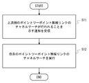
図3は、コントローラ104により行われる制御手順を示すフローチャートである。ステップS11では、コントローラ104は、上流側のポイントツーポイント無線リンクのチャネルサーチが行われることを示す通知を受信する。当該通知の受信に応答して、コントローラ104は、ステップS12において、自身のポイントツーポイント無線リンクのチャネルサーチを実行する。
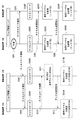
図4は、モバイルバックホール1000におけるチャネルサーチ及び使用無線チャネル変更を含む制御手順の一例を示すシーケンス図である。ステップS101では、ポイントツーポイント無線装置10Eは、順方向リンク12Eの受信品質の低下を検出する。使用無線チャネルの変更手順は、典型的には、特定の無線チャネルが他の無線システムから受ける干渉を回避するために行われる。したがって、使用無線チャネルの変更手順をトリガーするためにステップS101において監視される受信品質は、典型的には、Signal to Interference plus Noise Ratio(SINR)であってもよい。さらに、気象条件の悪化又は何らかの構造物による遮蔽によって順方向リンク12Eの見通し(line of sight)が劣化したことと区別するために、SINRに加えて受信信号強度(Received Signal Strength Indicator (RSSI))が使用されてもよい。
ステップS102では、順方向リンク12Eの受信品質の劣化が検出されたことに応答して、無線装置10Eは、逆方向リンク13Eの現在の使用無線チャネルを用いて、所定の通知を無線装置10Fに送信する。ステップS102の所定の通知は、一例において、無線装置10Eにおいて順方向リンク12Eのチャネルサーチが実行されることを示してもよい(チャネルサーチ通知)。これに代えて又はこれと組み合わせて、ステップS102の所定の通知は、順方向リンク12Eにおいて障害が検出されたことを示してもよいし、無線装置10Fに対する逆方向リンク13Eのチャネルサーチの実行要求を示してもよい。
ステップS103では、無線装置10Eは、下流側のポイントツーポイント無線システム1Aを構成する無線装置10Bに、所定の通知を送信する。ステップS103の所定の通知も、ステップS102の通知と同様に、順方向リンク12Eのチャネルサーチが実行されることを示してもよい(チャネルサーチ通知)。これに代えて又はこれと組み合わせて、ステップS103の所定の通知は、順方向リンク12Eにおいて障害が検出されたことを示してもよいし、下流側のポイントツーポイント無線リンク11Aのチャネルサーチの実行要求を示してもよい。無線装置10Bは、ステップS103の通知の受信に応答して、無線装置10Aによる順方向リンク12Aのチャネルサーチを開始するために、無線装置10Aにチャネルサーチ通知を送信する(ステップS104)。
ステップS105Aでは、無線装置10Aは、順方向リンク12Aのチャネルサーチを実行する。同様に、ステップS105Eでは、無線装置10Eは、順方向リンク12Eのチャネルサーチを実行する。なお、ステップS105Aでのチャネルサーチは、ステップS105Eでのチャネルサーチと完全に同期して行われる必要はない。ステップS105Aでのチャネルサーチは、ステップS105Eでのチャネルサーチを含む順方向リンク12Eの停止期間内において実行されることが好ましい。
ステップS106では、無線装置10Eは、ステップS105Eにおけるチャネルサーチの結果に基づいて、順方向リンク12Eの使用無線チャネルとして使用されるべき新たな無線チャネルを決定する。そして、無線装置10Eは、逆方向リンク13Eを用いて、チャネル変更指示を無線装置10Fに送信する。当該チャネル変更指示は、無線装置10Eにおいて決定された順方向リンク12Eの新たな使用無線チャネルを示す。
ステップS107E及びS107Fでは、無線装置10E及び10Fは共に、順方向リンク12Eの使用無線チャネルを、ステップS106において決定された新たな無線チャネルに変更する。ステップS107Eの動作は、ステップS106の変更指示の送信に応答して、又は当該変更指示の送信から所定の待機時間が経過したことに応答して開始されてもよい。ステップS107Fの動作は、ステップS106の変更指示の受信に応答して、又は当該変更指示の受信から所定の待機時間が経過したことに応答して開始されてもよい。これにより、順方向リンク12Eは、使用可能な状態に復帰する。
ステップS108、S109A、及びS109Bは、下流側のポイントツーポイント無線システム1Aでの順方向リンク12Aの使用無線チャネルの変更手順を示している。この変更手順は、上流側のポイントツーポイント無線システム1Eにおける手順(ステップS106、S107E、及びS107F)と同様に行われてもよい。なお、ステップS108、S109A、及びS109Bは、必ずしも必要ではない。既に説明したように、下流側のポイントツーポイント無線システム1Aでのチャネルサーチの結果は、例えば、将来の順方向リンク12Aの障害発生時に利用するためにポイントツーポイント無線システム1Aにて保持されてもよいし、図示されていないOAMシステムに送信されてもよい。
図4に示された使用無線チャネルの切り替え手順は、一例に過ぎない。使用無線チャネルを切り替えるためのシグナリング及び制御手順が様々に変形可能であることは、当業者であれば容易に理解されるであろう。例えば、図4では、順方向リンク(順方向リンク12E)の使用無線チャネルのみを切り替える手順を示しているが、順方向リンク12E及び逆方向リンク13Eの使用無線チャネルが同時に切り替えられてもよい。いくつかの変形例は、以下の第2及び第3の実施形態で説明される。
<第2の実施形態>
本実施形態は、第1の実施形態で説明された制御手順の変形例を説明する。本実施形態に係るポイントツーポイント無線システムの構成例は、図1と同様である。
本実施形態は、第1の実施形態で説明された制御手順の変形例を説明する。本実施形態に係るポイントツーポイント無線システムの構成例は、図1と同様である。
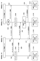
図5は、チャネルサーチ及び使用無線チャネル変更を含む制御手順の一例を示すシーケンス図である。図5の例では、図4の例と比べて、チャネルサーチ及び使用無線チャネル変更が双方向の無線リンクに対して行われるよう変形されている。
図5のステップS201~S204における処理は、図4のステップS101~S104における処理と同様であるから、ここでは説明を省略する。
ステップS205Aでは、無線装置10Aは、順方向リンク12Aのチャネルサーチを行う。ステップS205Bでは、無線装置10Bは、逆方向リンク13Aのチャネルサーチを行う。ステップS205Eでは、無線装置10Eは、順方向リンク12Eのチャネルサーチを行う。ステップS205Fでは、無線装置10Fは、逆方向リンク13Eのチャネルサーチを行う。
図5のステップS206、S207E、及びS207Fにおける処理は、図4のステップS106、S107E、及びS107Fにおける処理と同様であるから、ここでは説明を省略する。
ステップS208、S209E、及びS209Fは、上流側のポイントツーポイント無線システム1Eでの逆方向リンク13Eの使用無線チャネルの変更手順を示している。ステップS208、S209E、及びS209Fは、ステップS205Fのチャネルサーチにおいて逆方向リンク13Eの現在の使用無線チャネルよりも受信品質が良好な無線チャネルが発見された場合に行われるとよい。すなわち、ステップS208では、無線装置10Fは、ステップS205Fにおけるチャネルサーチの結果に基づいて、逆方向リンク13Eの使用無線チャネルとして使用されるべき新たな無線チャネルを決定する。そして、無線装置10Fは、順方向リンク12Eを用いて、チャネル変更指示を無線装置10Eに送信する。当該チャネル変更指示は、無線装置10Fにおいて決定された逆方向リンク13Eの新たな使用無線チャネルを示す。ステップS209E及びS209Fでは、無線装置10E及び10Fは共に、逆方向リンク13Eの使用無線チャネルを、ステップS208において決定された新たな使用無線チャネルに変更する。
ステップS210~S212、213A、及びS213Bは、下流側のポイントツーポイント無線システム1Aでの順方向リンク12A及び逆方向リンク13Aの使用無線チャネルの変更手順を示している。ステップS210では、無線装置10Aは、順方向リンク12Aのチャネルサーチ(ステップS205A)の結果を無線装置10Bに送信する。ステップS211では、無線装置10Bは、順方向リンク12A及び逆方向リンク13Aのチャネルサーチ(ステップS205A及びS205B)の結果に基づいて、順方向リンク12A及び逆方向リンク13Aの新たな使用無線チャネルを決定する。
ステップS212では、無線装置10Bは、チャネル変更指示を無線装置10Aに送信する。このチャネル変更指示は、ステップS211で決定されたリンク12A及び13Aの新たな使用無線チャネルを示す。ステップS213A及びS213Bでは、無線装置10A及び10Bは共に、順方向リンク12A及び逆方向リンク13Aの使用無線チャネルを、ステップS211において決定された新たな無線チャネルに変更する。
ステップS210~S212、213A、及びS213Bの変更手順は、一方の無線装置10Bが双方向の使用無線チャネルを決定する手順示している。しかしながら、この点は、適宜変更されてもよい。例えば、無線装置10Aが順方向リンク12Aの使用無線チャネルを決定し、無線装置10Bが逆順方向リンク13Aの使用無線チャネルを決定してもよい。また、ステップS210~S212並びにS213A及びS213Bの変更手順は、行われなくてもよい。
<第3の実施形態>
本実施形態は、第1の実施形態で説明された制御手順の変形例を説明する。本実施形態に係るポイントツーポイント無線システムの構成例は、図1と同様である。
本実施形態は、第1の実施形態で説明された制御手順の変形例を説明する。本実施形態に係るポイントツーポイント無線システムの構成例は、図1と同様である。
図6は、チャネルサーチ及び使用無線チャネル変更を含む制御手順の一例を示すシーケンス図である。図6の例では、2つのポイントツーポイント無線システム1A及び1Eの両方によるチャネルサーチの結果に基づいて、ポイントツーポイント無線システム1A及び1Eの各々の使用無線チャネルが決定される。
図6のステップS301~S304、S305A、及びS305Eにおける処理は、図4のステップS101~S104、S105A、及びS105Eにおける処理と同様であるから、ここでは説明を省略する。
ステップS306では、無線装置10Aは、順方向リンク12Aのチャネルサーチ(ステップS305A)の結果を無線装置10Bに送信する。ステップS307では、無線装置10Bは、受信した順方向リンク12Aのチャネルサーチ(ステップS305A)の結果を無線装置10Eに転送する。ステップS308では、無線装置10Eは、無線装置10Aによる順方向リンク12Aのチャネルサーチ結果、及び自身(無線装置10E)による順方向リンク12Eのチャネルサーチ結果の両方を用いて、順方向リンク12A及び12Eの各々の使用無線チャネルを決定する。
一例として、無線装置10Eは、順方向リンク12A及び12Eにおいて互いに異なる無線チャネル(無線周波数搬送波)が使用されるように、これらの使用無線チャネルを決定してもよい。これにより、順方向リンク12A及び12Eが互いに干渉し合うことを抑止できる。
他の例において、無線装置10Eは、順方向リンク12A及び12Eの2つのチャネルサーチにおいて共に良好な受信品質を得られた空き無線チャネル(clear channel又はunoccupied channel)の中から、順方向リンク12A及び12Eの各々の使用無線チャネルを決定してもよい。言い換えると、無線装置10Eは、順方向リンク12Aのチャネルサーチで得られた空き無線チャネル集合と順方向リンク12Eのチャネルサーチで得られた空き無線チャネル集合との積集合(共通部分、intersection)の中から、順方向リンク12A及び12Eの各々の使用無線チャネルを決定してもよい。ポイントツーポイント無線システム1Eがある無線チャネルにおいて他の無線システムから干渉を受けている場合、近くに配置されたポイントツーポイント無線システム1Aもその無線チャネルにおいて干渉を受けやすいかもしれない。ここで示した例によれば、このような干渉のおそれがある無線チャネルを選択から除外することができる。
図6に戻り説明を続ける。ステップS309では、無線装置10Eは、チャネル変更指示を無線装置10Fに送信する。このチャネル変更指示は、ステップS308で決定された順方向リンク12Eの新たな使用無線チャネルを示す。ステップS310E及びS310Fでは、無線装置10E及び10Fは共に、順方向リンク12Eの使用無線チャネルを、ステップS308において決定された新たな無線チャネルに変更する。
ステップS311では、無線装置10Eは、チャネル変更指示を無線装置10Bに送信する。このチャネル変更指示は、ステップS308で決定された順方向リンク12Aの新たな使用無線チャネルを示す。ステップS312では、無線装置10Bは、無線装置10Eから受信したチャネル変更指示を無線装置10Aに転送する。ステップS313A及びS313Bでは、無線装置10A及び10Bは共に、順方向リンク12Aの使用無線チャネルを、ステップS308において決定された新たな無線チャネルに変更する。
図6の手順は、一例に過ぎない。例えば、順方向リンク12A及び12Eの使用無線チャネルを決定する主体は、無線装置10Fではなく他の無線装置、例えば、無線装置10A又は10Bであってもよい。また、順方向リンク12A及び12Eの使用無線チャネルを決定する主体は、図示されていないOAMシステムであってもよい。この場合、無線装置10A及び10Eは、順方向リンク12Aのチャネルサーチ結果および順方向リンク12Eのチャネルサーチ結果をそれぞれOAMシステムに送信すればよい。
<その他の実施形態>
上述した第1~第3の実施形態は、適宜組み合わせて実施されてもよい。例えば、第2及び第3の実施形態を組み合わせてもよい。具体的は、逆方向リンク13A及び13Eの使用無線チャネルは、無線装置10Bによる逆方向リンク13Aのチャネルサーチ結果、及び無線装置10Fによる逆方向リンク13Eのチャネルサーチ結果の両方を用いて決定されてもよい。
上述した第1~第3の実施形態は、適宜組み合わせて実施されてもよい。例えば、第2及び第3の実施形態を組み合わせてもよい。具体的は、逆方向リンク13A及び13Eの使用無線チャネルは、無線装置10Bによる逆方向リンク13Aのチャネルサーチ結果、及び無線装置10Fによる逆方向リンク13Eのチャネルサーチ結果の両方を用いて決定されてもよい。
上述の無線装置10A、10B、10C、10D、10E、及び10Fによって行われるチャネルサーチ及び使用無線チャネル変更に関する処理は、Application Specific Integrated Circuit(ASIC)を含む半導体処理装置を用いて実現されてもよい。また、これらの処理は、少なくとも1つのプロセッサ(e.g. マイクロプロセッサ、Micro Processing Unit(MPU)、Central Processing Unit(CPU))を含むコンピュータにプログラムを実行させることによって実現されてもよい。具体的には、本明細書においてシーケンス図等を用いて説明されたアルゴリズムをコンピュータシステムに行わせるための命令群を含む一つ又は複数のプログラムを作成し、当該プログラムをコンピュータシステムに供給すればよい。
このプログラムは、様々なタイプの非一時的なコンピュータ可読媒体(non-transitory computer readable medium)を用いて格納され、コンピュータに供給することができる。非一時的なコンピュータ可読媒体は、様々なタイプの実体のある記録媒体(tangible storage medium)を含む。非一時的なコンピュータ可読媒体の例は、磁気記録媒体(e.g. フレキシブルディスク、磁気テープ、ハードディスクドライブ)、光磁気記録媒体(e.g. 光磁気ディスク)、Compact Disc Read Only Memory(CD-ROM)、CD-R、CD-R/W、半導体メモリ(e.g. マスクROM、Programmable ROM(PROM)、Erasable PROM(EPROM)、フラッシュROM、Random Access Memory(RAM))を含む。また、プログラムは、様々なタイプの一時的なコンピュータ可読媒体(transitory computer readable medium)によってコンピュータに供給されてもよい。一時的なコンピュータ可読媒体の例は、電気信号、光信号、及び電磁波を含む。一時的なコンピュータ可読媒体は、電線及び光ファイバ等の有線通信路、又は無線通信路を介して、プログラムをコンピュータに供給できる。
さらに、上述した実施形態は本件発明者により得られた技術思想の適用に関する例に過ぎない。すなわち、当該技術思想は、上述した実施形態のみに限定されるものではなく、種々の変更が可能であることは勿論である。
この出願は、2014年3月18日に出願された日本出願特願2014-054547を基礎とする優先権を主張し、その開示の全てをここに取り込む。
1A、1C、1E ポイントツーポイント無線システム
5A、5B 基地局
6 上位ネットワークノード
10A、10B、10C、10D、10E、10F ポイントツーポイント無線装置
11A、11C、11E ポイントツーポイント無線リンク
12A、12C、12E 順方向リンク
13A、13C、13E 逆方向リンク
20 パケット通信機器
101 無線インタフェース
102 LANインタフェース
103 レイヤ2スイッチ部
104 コントローラ
1000 モバイルバックホール
5A、5B 基地局
6 上位ネットワークノード
10A、10B、10C、10D、10E、10F ポイントツーポイント無線装置
11A、11C、11E ポイントツーポイント無線リンク
12A、12C、12E 順方向リンク
13A、13C、13E 逆方向リンク
20 パケット通信機器
101 無線インタフェース
102 LANインタフェース
103 レイヤ2スイッチ部
104 コントローラ
1000 モバイルバックホール
Claims (24)
- 対向装置との間に第1のポイントツーポイント無線リンクを確立し、前記第1のポイントツーポイント無線リンクを用いて前記対向装置と通信するよう構成された無線インタフェースと、
他のポイントツーポイント無線システムを含むネットワークに接続される通信インタフェースと、
前記無線インタフェースと前記通信インタフェースの間でトラフィックを中継するよう構成された信号処理手段と、
前記他のポイントツーポイント無線システムによって運用される第2のポイントツーポイント無線リンクが使用不能であることを示す第1の通知を受信した場合に、前記第1のポイントツーポイント無線リンクに使用可能な空き無線チャネルを探索する第1のチャネルサーチを行うよう構成された制御手段と、
を備えるポイントツーポイント無線装置。 - 前記第1の通知は、前記第2のポイントツーポイント無線リンクに使用可能な空き無線チャネルを探索する第2のチャネルサーチが行われる場合に前記他のポイントツーポイント無線システムから送信される制御メッセージを含む、請求項1に記載のポイントツーポイント無線装置。
- 前記制御メッセージは、前記第2のポイントツーポイント無線リンクに使用可能な空き無線チャネルを探索する第2のチャネルサーチが行われることを明示的又は暗示的に示す、請求項2に記載のポイントツーポイント無線装置。
- 前記制御メッセージは、前記第1のチャネルサーチの実行要求を含む、請求項2に記載のポイントツーポイント無線装置。
- 前記第1の通知は、前記第2のポイントツーポイント無線リンクが使用不能であることに起因する前記通信インタフェースのリンクダウンを含む、請求項1に記載のポイントツーポイント無線装置。
- 前記制御手段は、前記通信インタフェースを介して前記第1の通知を受信する、請求項1~5のいずれか1項に記載のポイントツーポイント無線装置。
- 前記ポイントツーポイント無線装置及び前記対向装置から構成される第1のポイントツーポイント無線システム並びに前記他のポイントツーポイント無線システムは共に、基地局と上位ネットワークノードの間の通信経路上に配置され且つ前記基地局と前記上位ネットワークノードの間を通信可能に接続するために使用され、
前記第1のポイントツーポイント無線システムは、前記他のポイントツーポイント無線システムに比べて、前記通信経路上において前記基地局に近い下流側に配置され、
前記他のポイントツーポイント無線システムは、前記第1のポイントツーポイント無線システムに比べて、前記通信経路上において前記上位ネットワークノードに近い上流側に配置される、
請求項1~6のいずれか1項に記載のポイントツーポイント無線装置。 - 前記制御手段は、前記第1のチャネルサーチの結果を前記他のポイントツーポイント無線システム、又はOperation and Maintenance(OAM)システムに送信し、前記第1のポイントツーポイント無線リンクで使用されるべき使用無線チャネルを示す第2の通知を前記他のポイントツーポイント無線システム又は前記OAMシステムから受信する、請求項1~7のいずれか1項に記載のポイントツーポイント無線装置。
- 前記使用無線チャネルは、前記第1のチャネルサーチの結果、及び前記第2のポイントツーポイント無線リンクに使用可能な空き無線チャネルを探索する第2のチャネルサーチの結果の両方に基づいて決定される、請求項8に記載のポイントツーポイント無線装置。
- 前記制御手段は、前記第2のポイントツーポイント無線リンクに使用可能な空き無線チャネルを探索する第2のチャネルサーチの結果を前記他のポイントツーポイント無線システムから受信し、前記第1のポイントツーポイント無線リンクで使用されるべき使用無線チャネルを前記第1のチャネルサーチの結果及び前記第2のチャネルサーチの結果の両方に基づいて決定する、請求項1~7のいずれか1項に記載のポイントツーポイント無線装置。
- 前記制御手段は、さらに、前記第1のチャネルサーチの結果及び前記第2のチャネルサーチの結果の両方に基づいて決定した前記第2のポイントツーポイント無線リンクで使用されるべき使用無線チャネルを前記他のポイントツーポイント無線システムに通知する、請求項10に記載のポイントツーポイント無線装置。
- 第1及び第2のポイントツーポイント無線リンクをそれぞれ運用する第1及び第2のポイントツーポイント無線システムを備え、
前記第1及び第2のポイントツーポイント無線システムは共に、基地局と上位ネットワークノードの間の通信経路上に配置され且つ前記基地局と前記上位ネットワークノードの間を通信可能に接続するために使用され、
前記第1のポイントツーポイント無線システムは、前記第2のポイントツーポイント無線システムに比べて、前記通信経路上において前記基地局に近い下流側に配置され、
前記第2のポイントツーポイント無線システムは、前記第1のポイントツーポイント無線システムに比べて、前記通信経路上において前記上位ネットワークノードに近い上流側に配置され、
前記第1のポイントツーポイント無線システムは、前記第2のポイントツーポイント無線リンクに使用可能な空き無線チャネルを探索する第2のチャネルサーチが行われる場合に、前記第1のポイントツーポイント無線リンクに使用可能な空き無線チャネルを探索する第1のチャネルサーチを行うよう構成されている、
モバイルバックホールシステム。 - 前記第1のポイントツーポイント無線システムは、前記第2のチャネルサーチが行われることを明示的又は暗示的に示す第1の通知を前記第2のポイントツーポイント無線システムから受信したことに応答して、前記第1のチャネルサーチを行う、請求項12に記載のモバイルバックホールシステム。
- 前記第1の通知は、前記第2のポイントツーポイント無線リンクが使用不能であることを示す、請求項13に記載のモバイルバックホールシステム。
- 前記第1の通知は、前記第1のチャネルサーチの実行要求を含む、請求項13に記載のモバイルバックホールシステム。
- 前記第1のポイントツーポイント無線システムは、前記第2のポイントツーポイント無線システムを含むネットワークに接続される通信インタフェースを備え、
前記第1の通知は、前記第2のポイントツーポイント無線リンクが使用不能であることに起因する前記通信インタフェースのリンクダウンを含む、請求項13に記載のモバイルバックホールシステム。 - 前記第1のポイントツーポイント無線システムは、前記第1のチャネルサーチの結果を前記第2のポイントツーポイント無線システム、又はOperation and Maintenance(OAM)システムに送信し、前記第1のポイントツーポイント無線リンクで使用されるべき使用無線チャネルを示す第2の通知を前記第2のポイントツーポイント無線システム又は前記OAMシステムから受信する、請求項12~16のいずれか1項に記載のモバイルバックホールシステム。
- 前記使用無線チャネルは、前記第1のチャネルサーチの結果及び前記第2のチャネルサーチの結果の両方に基づいて決定される、請求項17に記載のモバイルバックホールシステム。
- 前記第2のポイントツーポイント無線システムは、前記第1のチャネルサーチの結果を前記第1のポイントツーポイント無線システムから受信し、前記第2のポイントツーポイント無線リンクで使用されるべき使用無線チャネルを前記第1のチャネルサーチの結果及び前記第2のチャネルサーチの結果の両方に基づいて決定する、請求項12~18のいずれか1項に記載のモバイルバックホールシステム。
- 前記第2のポイントツーポイント無線システムは、さらに、前記第1のチャネルサーチの結果及び前記第2のチャネルサーチの結果の両方に基づいて決定した前記第1のポイントツーポイント無線リンクで使用されるべき使用無線チャネルを前記第1のポイントツーポイント無線システムに通知する、請求項19に記載のモバイルバックホールシステム。
- 前記第1のポイントツーポイント無線システムは、前記第2のチャネルサーチの結果を前記第2のポイントツーポイント無線システムから受信し、前記第1のポイントツーポイント無線リンクで使用されるべき使用無線チャネルを前記第1のチャネルサーチの結果及び前記第2のチャネルサーチの結果の両方に基づいて決定する、請求項12~16のいずれか1項に記載のモバイルバックホールシステム。
- 前記第1のポイントツーポイント無線システムは、さらに、前記第1のチャネルサーチの結果及び前記第2のチャネルサーチの結果の両方に基づいて決定した前記第2のポイントツーポイント無線リンクで使用されるべき使用無線チャネルを前記第2のポイントツーポイント無線システムに通知する、請求項21に記載のモバイルバックホールシステム。
- ポイントツーポイント無線装置により行われる通信制御方法であって、
他のポイントツーポイント無線システムによって運用される第2のポイントツーポイント無線リンクが使用不能であることを示す第1の通知を受信した場合に、前記ポイントツーポイント無線装置によって運用される第1のポイントツーポイント無線リンクに使用可能な空き無線チャネルを探索する第1のチャネルサーチを行うことを備える、
通信制御方法。 - 請求項23に記載の通信制御方法をコンピュータに行わせるためのプログラムを格納した非一時的なコンピュータ可読媒体。
Priority Applications (5)
| Application Number | Priority Date | Filing Date | Title |
|---|---|---|---|
| US15/121,473 US10123305B2 (en) | 2014-03-18 | 2015-02-18 | Point-to-point radio apparatus, mobile backhaul system, and communication control method |
| CN201580014473.XA CN106105297A (zh) | 2014-03-18 | 2015-02-18 | 点对点无线电设备、移动回程系统和通信控制方法 |
| EP15765382.5A EP3122101B1 (en) | 2014-03-18 | 2015-02-18 | Point-to-point wireless device, mobile backhaul system, and communication control method |
| US16/150,924 US10798681B2 (en) | 2014-03-18 | 2018-10-03 | Point-to-point radio apparatus, mobile backhaul system, and communication control method |
| US17/018,053 US11350386B2 (en) | 2014-03-18 | 2020-09-11 | Point-to-point radio apparatus, mobile backhaul system, and communication control method |
Applications Claiming Priority (2)
| Application Number | Priority Date | Filing Date | Title |
|---|---|---|---|
| JP2014-054547 | 2014-03-18 | ||
| JP2014054547A JP2015177497A (ja) | 2014-03-18 | 2014-03-18 | ポイントツーポイント無線装置、モバイルバックホールシステム、通信制御方法、及びプログラム |
Related Child Applications (2)
| Application Number | Title | Priority Date | Filing Date |
|---|---|---|---|
| US15/121,473 A-371-Of-International US10123305B2 (en) | 2014-03-18 | 2015-02-18 | Point-to-point radio apparatus, mobile backhaul system, and communication control method |
| US16/150,924 Continuation US10798681B2 (en) | 2014-03-18 | 2018-10-03 | Point-to-point radio apparatus, mobile backhaul system, and communication control method |
Publications (1)
| Publication Number | Publication Date |
|---|---|
| WO2015141125A1 true WO2015141125A1 (ja) | 2015-09-24 |
Family
ID=54144117
Family Applications (1)
| Application Number | Title | Priority Date | Filing Date |
|---|---|---|---|
| PCT/JP2015/000736 Ceased WO2015141125A1 (ja) | 2014-03-18 | 2015-02-18 | ポイントツーポイント無線装置、モバイルバックホールシステム、及び通信制御方法 |
Country Status (5)
| Country | Link |
|---|---|
| US (3) | US10123305B2 (ja) |
| EP (1) | EP3122101B1 (ja) |
| JP (1) | JP2015177497A (ja) |
| CN (1) | CN106105297A (ja) |
| WO (1) | WO2015141125A1 (ja) |
Families Citing this family (3)
| Publication number | Priority date | Publication date | Assignee | Title |
|---|---|---|---|---|
| CN116916458A (zh) | 2018-06-21 | 2023-10-20 | 中兴通讯股份有限公司 | 信息传输方法及装置 |
| WO2021115546A1 (en) | 2019-12-09 | 2021-06-17 | Telefonaktiebolaget Lm Ericsson (Publ) | Classification of microwave link data |
| JP7520515B2 (ja) | 2020-01-09 | 2024-07-23 | キヤノン株式会社 | 通信装置、制御方法、及びプログラム |
Citations (4)
| Publication number | Priority date | Publication date | Assignee | Title |
|---|---|---|---|---|
| WO2009014764A1 (en) * | 2007-07-25 | 2009-01-29 | Teenay Wireless, Inc. | A multi-tier backhaul network system with traffic differentiation and advanced processing capabilities and methods therefor |
| JP2011205638A (ja) * | 2010-03-25 | 2011-10-13 | Toshiba Corp | フェムトセルにおける自動障害報告 |
| JP2013021648A (ja) * | 2011-07-14 | 2013-01-31 | Nippon Telegr & Teleph Corp <Ntt> | 無線中継装置および無線中継方法 |
| JP2013102361A (ja) * | 2011-11-09 | 2013-05-23 | Hitachi Ltd | 移動体通信システム、迂回経路構築方法およびセンタ監視装置 |
Family Cites Families (26)
| Publication number | Priority date | Publication date | Assignee | Title |
|---|---|---|---|---|
| US6498844B1 (en) * | 1996-11-22 | 2002-12-24 | Siemens Aktiengesellschaft | Method and system of dynamic traffic control in a communication network |
| EP1435146B1 (en) | 2001-10-12 | 2005-05-18 | Nokia Corporation | Adaptive point-to-point microwave radio system |
| CN102595584B (zh) * | 2005-09-21 | 2015-07-22 | Lg电子株式会社 | 在多载波无线系统中建立附加反向链路载波 |
| US20070218910A1 (en) * | 2006-03-15 | 2007-09-20 | Motorola, Inc. | Dynamic beam steering of backhaul traffic |
| US7688835B2 (en) * | 2006-03-15 | 2010-03-30 | Motorola, Inc. | Dynamic wireless backhaul |
| WO2008026868A2 (en) * | 2006-08-31 | 2008-03-06 | Lg Electronics Inc. | Methods of changing channels and configuring a sub-networ in a wireless network |
| US8718561B2 (en) * | 2007-11-20 | 2014-05-06 | Aruba Networks, Inc. | Method and apparatus for detecting and avoiding interference in a communications network |
| WO2011099802A2 (en) * | 2010-02-11 | 2011-08-18 | Lg Electronics Inc. | Method and apparatus of recovering backhaul link failure between base station and relay node |
| US8948085B2 (en) * | 2010-03-17 | 2015-02-03 | Qualcomm Incorporated | Methods and apparatus for best-effort radio backhaul among cells on unlicensed or shared spectrum |
| JP5451521B2 (ja) | 2010-05-18 | 2014-03-26 | 日本電気株式会社 | データ通信システム、データ通信装置、データ通信装置の制御方法、プログラム及び記録媒体 |
| US8744506B2 (en) * | 2010-06-17 | 2014-06-03 | Qualcomm Incorporated | Device discovery on white space frequencies |
| CN102300270B (zh) * | 2010-06-25 | 2015-01-14 | 电信科学技术研究院 | 回程链路控制信道信息的资源配置方法和设备 |
| US8305966B2 (en) * | 2010-06-29 | 2012-11-06 | Intel Corporation | Femto backhaul fault detection and recovery |
| US9749880B2 (en) * | 2010-06-30 | 2017-08-29 | Verizon Patent And Licensing Inc. | Base station failover using neighboring base stations as relays |
| US8824311B2 (en) * | 2010-09-13 | 2014-09-02 | Blinq Wireless Inc. | System and method for co-channel interference measurement and managed adaptive resource allocation for wireless backhaul |
| WO2012068224A1 (en) * | 2010-11-16 | 2012-05-24 | Interdigital Patent Holdings, Inc. | Method and apparatus for wireless direct link operation |
| US20120224472A1 (en) * | 2011-03-04 | 2012-09-06 | Electronics And Telecommunications Research Institute | Method for relaying of base station, method for relaying of terminal and method for transmitting |
| US8804502B2 (en) * | 2011-06-28 | 2014-08-12 | At&T Mobility Ii Llc | Emergency backhaul links for wireless telecommunications networks |
| US8989762B1 (en) * | 2013-12-05 | 2015-03-24 | CBF Networks, Inc. | Advanced backhaul services |
| US8502733B1 (en) * | 2012-02-10 | 2013-08-06 | CBF Networks, Inc. | Transmit co-channel spectrum sharing |
| EP2842381B1 (en) * | 2012-04-23 | 2017-09-06 | Intel Corporation | Systems and methods for avoiding interference for a peer-to-peer network connection |
| WO2014043665A2 (en) * | 2012-09-17 | 2014-03-20 | Interdigital Patent Holdings, Inc. | Self-optimization of backhaul radio reseources and small cell backhaul delay estimation |
| US9078157B2 (en) * | 2012-12-31 | 2015-07-07 | Verizon Patent And Licensing Inc. | Quick recovery of RF sessions after backhaul link failure |
| KR20140088375A (ko) * | 2013-01-02 | 2014-07-10 | 삼성전자주식회사 | 무선 통신 시스템에서 기지국 간 무선 링크 복구를 위한 방법 및 장치 |
| US10021600B2 (en) * | 2013-01-02 | 2018-07-10 | Qualcomm Incorporated | Backhaul traffic reliability in unlicensed bands using spectrum sensing and channel reservation |
| US10554482B2 (en) * | 2016-03-18 | 2020-02-04 | Plume Design, Inc. | Optimization of distributed Wi-Fi networks estimation and learning |
-
2014
- 2014-03-18 JP JP2014054547A patent/JP2015177497A/ja not_active Abandoned
-
2015
- 2015-02-18 EP EP15765382.5A patent/EP3122101B1/en active Active
- 2015-02-18 CN CN201580014473.XA patent/CN106105297A/zh active Pending
- 2015-02-18 WO PCT/JP2015/000736 patent/WO2015141125A1/ja not_active Ceased
- 2015-02-18 US US15/121,473 patent/US10123305B2/en active Active
-
2018
- 2018-10-03 US US16/150,924 patent/US10798681B2/en active Active
-
2020
- 2020-09-11 US US17/018,053 patent/US11350386B2/en active Active
Patent Citations (4)
| Publication number | Priority date | Publication date | Assignee | Title |
|---|---|---|---|---|
| WO2009014764A1 (en) * | 2007-07-25 | 2009-01-29 | Teenay Wireless, Inc. | A multi-tier backhaul network system with traffic differentiation and advanced processing capabilities and methods therefor |
| JP2011205638A (ja) * | 2010-03-25 | 2011-10-13 | Toshiba Corp | フェムトセルにおける自動障害報告 |
| JP2013021648A (ja) * | 2011-07-14 | 2013-01-31 | Nippon Telegr & Teleph Corp <Ntt> | 無線中継装置および無線中継方法 |
| JP2013102361A (ja) * | 2011-11-09 | 2013-05-23 | Hitachi Ltd | 移動体通信システム、迂回経路構築方法およびセンタ監視装置 |
Also Published As
| Publication number | Publication date |
|---|---|
| US20200413375A1 (en) | 2020-12-31 |
| US11350386B2 (en) | 2022-05-31 |
| US20190037536A1 (en) | 2019-01-31 |
| US20170006579A1 (en) | 2017-01-05 |
| CN106105297A (zh) | 2016-11-09 |
| JP2015177497A (ja) | 2015-10-05 |
| US10798681B2 (en) | 2020-10-06 |
| EP3122101A1 (en) | 2017-01-25 |
| EP3122101B1 (en) | 2020-12-23 |
| EP3122101A4 (en) | 2017-11-08 |
| US10123305B2 (en) | 2018-11-06 |
Similar Documents
| Publication | Publication Date | Title |
|---|---|---|
| CN112689974B (zh) | 无线接入网中的路由选择和服务质量支持 | |
| JP6870856B2 (ja) | 二重接続における無線リンク障害ハンドリング | |
| EP3815324B1 (en) | Dynamic route selection in integrated access and backhaul system | |
| JP6451783B2 (ja) | 第1の基地局及びその方法 | |
| US9130834B2 (en) | Method and device for monitoring backbone inter base-station communication | |
| EP3028501B1 (en) | Methods and apparatus for dual connectivity | |
| KR20210141696A (ko) | 링크상태 통지 방법 및 장치, 링크 처리 방법 및 장치, 저장매체, 전자장치 | |
| CN112534874A (zh) | 用于处置链路转换的第一网络节点、无线装置以及由此执行的方法 | |
| EP4224902B1 (en) | Communication control method | |
| US20230269653A1 (en) | Rerouting method and apparatus, and communication device | |
| US11350386B2 (en) | Point-to-point radio apparatus, mobile backhaul system, and communication control method | |
| US12581386B2 (en) | Communication apparatus, control method of communication apparatus, and computer-readable storage medium | |
| US8954057B2 (en) | Base station, detection device, communication system and detection method | |
| EP3586561B1 (en) | Method and devices for dual connectivity between a dual protocol stack user equipment and two baseband units of a radio access telecommunications network | |
| WO2010123121A1 (ja) | 無線基地局及びコネクション確立制御方法 | |
| EP4080913B1 (en) | Communication method and apparatus | |
| JP2017509285A (ja) | 構成方法、ネットワークデバイス、およびユーザ機器 | |
| WO2023026681A1 (ja) | 中継装置、制御方法、プログラム、及び通信システム | |
| US20240388993A1 (en) | Control apparatus, control method, and non-transitory computer-readable storage medium |
Legal Events
| Date | Code | Title | Description |
|---|---|---|---|
| 121 | Ep: the epo has been informed by wipo that ep was designated in this application |
Ref document number: 15765382 Country of ref document: EP Kind code of ref document: A1 |
|
| WWE | Wipo information: entry into national phase |
Ref document number: 15121473 Country of ref document: US |
|
| NENP | Non-entry into the national phase |
Ref country code: DE |
|
| REEP | Request for entry into the european phase |
Ref document number: 2015765382 Country of ref document: EP |
|
| WWE | Wipo information: entry into national phase |
Ref document number: 2015765382 Country of ref document: EP |