WO2015141449A1 - 作業機械 - Google Patents
作業機械 Download PDFInfo
- Publication number
- WO2015141449A1 WO2015141449A1 PCT/JP2015/055943 JP2015055943W WO2015141449A1 WO 2015141449 A1 WO2015141449 A1 WO 2015141449A1 JP 2015055943 W JP2015055943 W JP 2015055943W WO 2015141449 A1 WO2015141449 A1 WO 2015141449A1
- Authority
- WO
- WIPO (PCT)
- Prior art keywords
- inverter
- synchronous generator
- motor
- short
- current
- Prior art date
- Legal status (The legal status is an assumption and is not a legal conclusion. Google has not performed a legal analysis and makes no representation as to the accuracy of the status listed.)
- Ceased
Links
Images


Classifications
-
- E—FIXED CONSTRUCTIONS
- E02—HYDRAULIC ENGINEERING; FOUNDATIONS; SOIL SHIFTING
- E02F—DREDGING; SOIL-SHIFTING
- E02F9/00—Component parts of dredgers or soil-shifting machines, not restricted to one of the kinds covered by groups E02F3/00 - E02F7/00
- E02F9/26—Indicating devices
- E02F9/267—Diagnosing or detecting failure of vehicles
- E02F9/268—Diagnosing or detecting failure of vehicles with failure correction follow-up actions
-
- B—PERFORMING OPERATIONS; TRANSPORTING
- B60—VEHICLES IN GENERAL
- B60L—PROPULSION OF ELECTRICALLY-PROPELLED VEHICLES; SUPPLYING ELECTRIC POWER FOR AUXILIARY EQUIPMENT OF ELECTRICALLY-PROPELLED VEHICLES; ELECTRODYNAMIC BRAKE SYSTEMS FOR VEHICLES IN GENERAL; MAGNETIC SUSPENSION OR LEVITATION FOR VEHICLES; MONITORING OPERATING VARIABLES OF ELECTRICALLY-PROPELLED VEHICLES; ELECTRIC SAFETY DEVICES FOR ELECTRICALLY-PROPELLED VEHICLES
- B60L3/00—Electric devices on electrically-propelled vehicles for safety purposes; Monitoring operating variables, e.g. speed, deceleration or energy consumption
- B60L3/0023—Detecting, eliminating, remedying or compensating for drive train abnormalities, e.g. failures within the drive train
- B60L3/003—Detecting, eliminating, remedying or compensating for drive train abnormalities, e.g. failures within the drive train relating to inverters
-
- B—PERFORMING OPERATIONS; TRANSPORTING
- B60—VEHICLES IN GENERAL
- B60L—PROPULSION OF ELECTRICALLY-PROPELLED VEHICLES; SUPPLYING ELECTRIC POWER FOR AUXILIARY EQUIPMENT OF ELECTRICALLY-PROPELLED VEHICLES; ELECTRODYNAMIC BRAKE SYSTEMS FOR VEHICLES IN GENERAL; MAGNETIC SUSPENSION OR LEVITATION FOR VEHICLES; MONITORING OPERATING VARIABLES OF ELECTRICALLY-PROPELLED VEHICLES; ELECTRIC SAFETY DEVICES FOR ELECTRICALLY-PROPELLED VEHICLES
- B60L3/00—Electric devices on electrically-propelled vehicles for safety purposes; Monitoring operating variables, e.g. speed, deceleration or energy consumption
- B60L3/0023—Detecting, eliminating, remedying or compensating for drive train abnormalities, e.g. failures within the drive train
- B60L3/0061—Detecting, eliminating, remedying or compensating for drive train abnormalities, e.g. failures within the drive train relating to electrical machines
-
- B—PERFORMING OPERATIONS; TRANSPORTING
- B60—VEHICLES IN GENERAL
- B60L—PROPULSION OF ELECTRICALLY-PROPELLED VEHICLES; SUPPLYING ELECTRIC POWER FOR AUXILIARY EQUIPMENT OF ELECTRICALLY-PROPELLED VEHICLES; ELECTRODYNAMIC BRAKE SYSTEMS FOR VEHICLES IN GENERAL; MAGNETIC SUSPENSION OR LEVITATION FOR VEHICLES; MONITORING OPERATING VARIABLES OF ELECTRICALLY-PROPELLED VEHICLES; ELECTRIC SAFETY DEVICES FOR ELECTRICALLY-PROPELLED VEHICLES
- B60L50/00—Electric propulsion with power supplied within the vehicle
- B60L50/10—Electric propulsion with power supplied within the vehicle using propulsion power supplied by engine-driven generators, e.g. generators driven by combustion engines
- B60L50/13—Electric propulsion with power supplied within the vehicle using propulsion power supplied by engine-driven generators, e.g. generators driven by combustion engines using AC generators and AC motors
-
- B—PERFORMING OPERATIONS; TRANSPORTING
- B60—VEHICLES IN GENERAL
- B60L—PROPULSION OF ELECTRICALLY-PROPELLED VEHICLES; SUPPLYING ELECTRIC POWER FOR AUXILIARY EQUIPMENT OF ELECTRICALLY-PROPELLED VEHICLES; ELECTRODYNAMIC BRAKE SYSTEMS FOR VEHICLES IN GENERAL; MAGNETIC SUSPENSION OR LEVITATION FOR VEHICLES; MONITORING OPERATING VARIABLES OF ELECTRICALLY-PROPELLED VEHICLES; ELECTRIC SAFETY DEVICES FOR ELECTRICALLY-PROPELLED VEHICLES
- B60L50/00—Electric propulsion with power supplied within the vehicle
- B60L50/50—Electric propulsion with power supplied within the vehicle using propulsion power supplied by batteries or fuel cells
- B60L50/60—Electric propulsion with power supplied within the vehicle using propulsion power supplied by batteries or fuel cells using power supplied by batteries
- B60L50/61—Electric propulsion with power supplied within the vehicle using propulsion power supplied by batteries or fuel cells using power supplied by batteries by batteries charged by engine-driven generators, e.g. series hybrid electric vehicles
-
- E—FIXED CONSTRUCTIONS
- E02—HYDRAULIC ENGINEERING; FOUNDATIONS; SOIL SHIFTING
- E02F—DREDGING; SOIL-SHIFTING
- E02F9/00—Component parts of dredgers or soil-shifting machines, not restricted to one of the kinds covered by groups E02F3/00 - E02F7/00
- E02F9/20—Drives; Control devices
- E02F9/2058—Electric or electro-mechanical or mechanical control devices of vehicle sub-units
- E02F9/2062—Control of propulsion units
- E02F9/2075—Control of propulsion units of the hybrid type
-
- B—PERFORMING OPERATIONS; TRANSPORTING
- B60—VEHICLES IN GENERAL
- B60L—PROPULSION OF ELECTRICALLY-PROPELLED VEHICLES; SUPPLYING ELECTRIC POWER FOR AUXILIARY EQUIPMENT OF ELECTRICALLY-PROPELLED VEHICLES; ELECTRODYNAMIC BRAKE SYSTEMS FOR VEHICLES IN GENERAL; MAGNETIC SUSPENSION OR LEVITATION FOR VEHICLES; MONITORING OPERATING VARIABLES OF ELECTRICALLY-PROPELLED VEHICLES; ELECTRIC SAFETY DEVICES FOR ELECTRICALLY-PROPELLED VEHICLES
- B60L2240/00—Control parameters of input or output; Target parameters
- B60L2240/40—Drive Train control parameters
- B60L2240/42—Drive Train control parameters related to electric machines
- B60L2240/421—Speed
-
- B—PERFORMING OPERATIONS; TRANSPORTING
- B60—VEHICLES IN GENERAL
- B60L—PROPULSION OF ELECTRICALLY-PROPELLED VEHICLES; SUPPLYING ELECTRIC POWER FOR AUXILIARY EQUIPMENT OF ELECTRICALLY-PROPELLED VEHICLES; ELECTRODYNAMIC BRAKE SYSTEMS FOR VEHICLES IN GENERAL; MAGNETIC SUSPENSION OR LEVITATION FOR VEHICLES; MONITORING OPERATING VARIABLES OF ELECTRICALLY-PROPELLED VEHICLES; ELECTRIC SAFETY DEVICES FOR ELECTRICALLY-PROPELLED VEHICLES
- B60L2240/00—Control parameters of input or output; Target parameters
- B60L2240/40—Drive Train control parameters
- B60L2240/42—Drive Train control parameters related to electric machines
- B60L2240/423—Torque
-
- B—PERFORMING OPERATIONS; TRANSPORTING
- B60—VEHICLES IN GENERAL
- B60L—PROPULSION OF ELECTRICALLY-PROPELLED VEHICLES; SUPPLYING ELECTRIC POWER FOR AUXILIARY EQUIPMENT OF ELECTRICALLY-PROPELLED VEHICLES; ELECTRODYNAMIC BRAKE SYSTEMS FOR VEHICLES IN GENERAL; MAGNETIC SUSPENSION OR LEVITATION FOR VEHICLES; MONITORING OPERATING VARIABLES OF ELECTRICALLY-PROPELLED VEHICLES; ELECTRIC SAFETY DEVICES FOR ELECTRICALLY-PROPELLED VEHICLES
- B60L2240/00—Control parameters of input or output; Target parameters
- B60L2240/40—Drive Train control parameters
- B60L2240/42—Drive Train control parameters related to electric machines
- B60L2240/427—Voltage
-
- B—PERFORMING OPERATIONS; TRANSPORTING
- B60—VEHICLES IN GENERAL
- B60L—PROPULSION OF ELECTRICALLY-PROPELLED VEHICLES; SUPPLYING ELECTRIC POWER FOR AUXILIARY EQUIPMENT OF ELECTRICALLY-PROPELLED VEHICLES; ELECTRODYNAMIC BRAKE SYSTEMS FOR VEHICLES IN GENERAL; MAGNETIC SUSPENSION OR LEVITATION FOR VEHICLES; MONITORING OPERATING VARIABLES OF ELECTRICALLY-PROPELLED VEHICLES; ELECTRIC SAFETY DEVICES FOR ELECTRICALLY-PROPELLED VEHICLES
- B60L2240/00—Control parameters of input or output; Target parameters
- B60L2240/40—Drive Train control parameters
- B60L2240/42—Drive Train control parameters related to electric machines
- B60L2240/429—Current
-
- B—PERFORMING OPERATIONS; TRANSPORTING
- B60—VEHICLES IN GENERAL
- B60L—PROPULSION OF ELECTRICALLY-PROPELLED VEHICLES; SUPPLYING ELECTRIC POWER FOR AUXILIARY EQUIPMENT OF ELECTRICALLY-PROPELLED VEHICLES; ELECTRODYNAMIC BRAKE SYSTEMS FOR VEHICLES IN GENERAL; MAGNETIC SUSPENSION OR LEVITATION FOR VEHICLES; MONITORING OPERATING VARIABLES OF ELECTRICALLY-PROPELLED VEHICLES; ELECTRIC SAFETY DEVICES FOR ELECTRICALLY-PROPELLED VEHICLES
- B60L2240/00—Control parameters of input or output; Target parameters
- B60L2240/40—Drive Train control parameters
- B60L2240/44—Drive Train control parameters related to combustion engines
- B60L2240/441—Speed
-
- B—PERFORMING OPERATIONS; TRANSPORTING
- B60—VEHICLES IN GENERAL
- B60L—PROPULSION OF ELECTRICALLY-PROPELLED VEHICLES; SUPPLYING ELECTRIC POWER FOR AUXILIARY EQUIPMENT OF ELECTRICALLY-PROPELLED VEHICLES; ELECTRODYNAMIC BRAKE SYSTEMS FOR VEHICLES IN GENERAL; MAGNETIC SUSPENSION OR LEVITATION FOR VEHICLES; MONITORING OPERATING VARIABLES OF ELECTRICALLY-PROPELLED VEHICLES; ELECTRIC SAFETY DEVICES FOR ELECTRICALLY-PROPELLED VEHICLES
- B60L2240/00—Control parameters of input or output; Target parameters
- B60L2240/40—Drive Train control parameters
- B60L2240/52—Drive Train control parameters related to converters
- B60L2240/527—Voltage
-
- B—PERFORMING OPERATIONS; TRANSPORTING
- B60—VEHICLES IN GENERAL
- B60L—PROPULSION OF ELECTRICALLY-PROPELLED VEHICLES; SUPPLYING ELECTRIC POWER FOR AUXILIARY EQUIPMENT OF ELECTRICALLY-PROPELLED VEHICLES; ELECTRODYNAMIC BRAKE SYSTEMS FOR VEHICLES IN GENERAL; MAGNETIC SUSPENSION OR LEVITATION FOR VEHICLES; MONITORING OPERATING VARIABLES OF ELECTRICALLY-PROPELLED VEHICLES; ELECTRIC SAFETY DEVICES FOR ELECTRICALLY-PROPELLED VEHICLES
- B60L2240/00—Control parameters of input or output; Target parameters
- B60L2240/40—Drive Train control parameters
- B60L2240/52—Drive Train control parameters related to converters
- B60L2240/529—Current
-
- Y—GENERAL TAGGING OF NEW TECHNOLOGICAL DEVELOPMENTS; GENERAL TAGGING OF CROSS-SECTIONAL TECHNOLOGIES SPANNING OVER SEVERAL SECTIONS OF THE IPC; TECHNICAL SUBJECTS COVERED BY FORMER USPC CROSS-REFERENCE ART COLLECTIONS [XRACs] AND DIGESTS
- Y02—TECHNOLOGIES OR APPLICATIONS FOR MITIGATION OR ADAPTATION AGAINST CLIMATE CHANGE
- Y02T—CLIMATE CHANGE MITIGATION TECHNOLOGIES RELATED TO TRANSPORTATION
- Y02T10/00—Road transport of goods or passengers
- Y02T10/60—Other road transportation technologies with climate change mitigation effect
- Y02T10/62—Hybrid vehicles
-
- Y—GENERAL TAGGING OF NEW TECHNOLOGICAL DEVELOPMENTS; GENERAL TAGGING OF CROSS-SECTIONAL TECHNOLOGIES SPANNING OVER SEVERAL SECTIONS OF THE IPC; TECHNICAL SUBJECTS COVERED BY FORMER USPC CROSS-REFERENCE ART COLLECTIONS [XRACs] AND DIGESTS
- Y02—TECHNOLOGIES OR APPLICATIONS FOR MITIGATION OR ADAPTATION AGAINST CLIMATE CHANGE
- Y02T—CLIMATE CHANGE MITIGATION TECHNOLOGIES RELATED TO TRANSPORTATION
- Y02T10/00—Road transport of goods or passengers
- Y02T10/60—Other road transportation technologies with climate change mitigation effect
- Y02T10/64—Electric machine technologies in electromobility
-
- Y—GENERAL TAGGING OF NEW TECHNOLOGICAL DEVELOPMENTS; GENERAL TAGGING OF CROSS-SECTIONAL TECHNOLOGIES SPANNING OVER SEVERAL SECTIONS OF THE IPC; TECHNICAL SUBJECTS COVERED BY FORMER USPC CROSS-REFERENCE ART COLLECTIONS [XRACs] AND DIGESTS
- Y02—TECHNOLOGIES OR APPLICATIONS FOR MITIGATION OR ADAPTATION AGAINST CLIMATE CHANGE
- Y02T—CLIMATE CHANGE MITIGATION TECHNOLOGIES RELATED TO TRANSPORTATION
- Y02T10/00—Road transport of goods or passengers
- Y02T10/60—Other road transportation technologies with climate change mitigation effect
- Y02T10/70—Energy storage systems for electromobility, e.g. batteries
-
- Y—GENERAL TAGGING OF NEW TECHNOLOGICAL DEVELOPMENTS; GENERAL TAGGING OF CROSS-SECTIONAL TECHNOLOGIES SPANNING OVER SEVERAL SECTIONS OF THE IPC; TECHNICAL SUBJECTS COVERED BY FORMER USPC CROSS-REFERENCE ART COLLECTIONS [XRACs] AND DIGESTS
- Y02—TECHNOLOGIES OR APPLICATIONS FOR MITIGATION OR ADAPTATION AGAINST CLIMATE CHANGE
- Y02T—CLIMATE CHANGE MITIGATION TECHNOLOGIES RELATED TO TRANSPORTATION
- Y02T10/00—Road transport of goods or passengers
- Y02T10/60—Other road transportation technologies with climate change mitigation effect
- Y02T10/7072—Electromobility specific charging systems or methods for batteries, ultracapacitors, supercapacitors or double-layer capacitors
Definitions
- the present invention relates to a work machine including a permanent magnet type synchronous generator for driving a drive unit such as a traveling device.
- Patent Document 1 a conventional technique using a permanent magnet type synchronous generator of this type is disclosed in Patent Document 1, for example.
- the inverter part which controls the three-phase alternating current motor which is a permanent magnet type synchronous generator, and the electric current detection means which detects the electric current which flows through this inverter part are provided. Then, when a current exceeding a preset current value is detected by the current detection means, after the operation of the inverter unit is stopped, a switching pattern for short circuit detection is applied to the switching element in the inverter unit. It is set as the structure which detects a short circuit location using.
- the present invention has been made from the actual situation in the above-described prior art, and an object of the present invention is to provide a work machine capable of reliably detecting a short circuit in a synchronous generator that generates power by a drive source.
- the present invention provides a drive source, a synchronous generator that generates electric power by the drive source, an inverter having a current detection unit and a switching element that detect a current flowing through the synchronous generator, and the inverter And a control unit that detects an electrical abnormality of the synchronous generator, and the control unit detects an electrical abnormality of the synchronous generator
- the gate of the switching element of the inverter is turned off, and the current detection unit continuously detects a current of a predetermined value or more for a predetermined time or longer in this state, it is determined that the inverter is in a short circuit state. It is characterized by that.
- the present invention is configured as described above, and even when the gate of the switching element of the inverter that controls the synchronous generator is turned off, a current larger than a predetermined value continuously flows in the inverter for a predetermined time or more. Since it is determined that the inverter is in a short-circuited state when detected, the short-circuited state of the inverter can be reliably detected even in a state where the synchronous generator generates electromotive force by the drive source. Problems, configurations, and effects other than those described above will be made clear from the following description of embodiments.
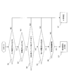
- FIG. 1 is a side view showing a hybrid wheel loader according to a first embodiment of the present invention. It is a schematic block diagram which shows the drive system of a hybrid type wheel loader. It is a flowchart for demonstrating the basic idea for detecting the inverter short circuit abnormality by this invention.
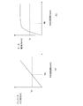
- 3 is a flowchart for detecting a short circuit state according to the first embodiment of the present invention; It is a figure which shows the characteristic with respect to the rotation speed of a synchronous generator, (a) is a graph which shows the inverter input voltage characteristic at the time of normal when the inverter input voltage is not controlled, (b) shows the motor current characteristic at the time of a short circuit state. It is a graph to show. It is a schematic block diagram which shows the drive system of the electrically driven wheel loader which concerns on 2nd Embodiment of this invention. It is a flowchart for detecting the short circuit state of the synchronous generator by 2nd Embodiment.
- FIG. 1 is a side view showing a hybrid wheel loader according to a first embodiment of the present invention.
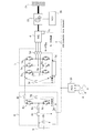
- FIG. 2 is a schematic configuration diagram showing a drive system of the hybrid wheel loader.
- a hybrid wheel loader 1 is a traveling electric drive type wheel loader having a drive system in which a traveling unit 2 is electrified, and is a hybrid construction vehicle equipped with a so-called series type hybrid system. is there.
- the hybrid work machine according to the present invention includes not only one that assists hydraulic driving but also one that assists driving by another electric motor.
- a front work machine 1b as a drive unit used for excavation work such as earth and sand is provided on the front side of the vehicle body 1a of the hybrid wheel loader 1.
- a traveling wheel 2a is attached to the vehicle body 1a as a traveling tire that allows the vehicle body 1a to move forward or backward, that is, to travel. These traveling wheels 2a constitute a part of the traveling unit 2, and are driven by an electric traveling motor 6 mounted on the vehicle body 1a.
- the front work machine 1b includes a lift arm 1c that is connected to the front side of the vehicle body 1a so as to be rotatable in the vertical direction, and a bucket 1d that is rotatably connected to a tip portion of the lift arm 1c.
- the lift arm 1c is driven by a lift arm cylinder (hydraulic cylinder) 1e which is a hydraulic actuator.
- the bucket 1d is driven by transmitting the operation of a bucket cylinder (hydraulic cylinder) 1f, which is a hydraulic actuator, to the bell crank 1g.
- the lift arm cylinder 1e and the bucket cylinder 1f are extended and contracted by hydraulic pressure of hydraulic oil supplied from an engine 3 as a drive source and a hydraulic pump (not shown) driven by a motor / generator (MG) 4 described later. Is done.
- the hybrid wheel loader 1 includes an engine 3 as a power source.
- a starter 3 a for starting the engine 3 is attached to the engine 3.
- the engine 3 has its engine speed controlled by a command from an engine control unit (ECU) 3b as an engine control device.
- An output shaft 3c of the engine 3 and a drive shaft of an MG (motor / generator) 4 serving as a generator motor are mechanically connected to each other, and each rotational torque is supplied to a hydraulic pump (not shown).
- This MG4 is constituted by a permanent magnet type synchronous generator.
- the MG 4 operates as a motor when torque assisting the engine 3 and contributes to driving of the hydraulic pump, while the motor / motor that operates as a generator that generates power using the engine 3 as a driving source during steady running or deceleration. It is a generator. Further, a rotation sensor 4a for detecting the rotation speed (motor rotation speed) of MG4 is attached to MG4.
- the MG 4 is connected to an MG inverter 5 as a power converter, and is controlled by the MG inverter 5.
- the MG inverter 5 supplies electric power from a power storage device 9 to be described later to the MG 4 to drive the MG 4 as a motor, or conversely, when the MG 4 is operating as a generator by the engine 3, It is a three-phase inverter device for supplying.
- the MG inverter 5 includes semiconductor switches 5a and 5b, such as IGBTs (Insulated Gate Bipolar Transistors), as switching elements. These semiconductor switches 5a and 5b are generally power semiconductor elements and are a bridge circuit composed of a total of six.
- the source of the semiconductor switch 5a and the drain of the semiconductor switch 5b are electrically connected to the MG 4 via the motor current sensor 5d.
- the motor current sensor 5d is a current detection unit that detects a current (motor current) output from the MG 4.
- a main smoothing capacitor 5e and an inverter input voltage sensor 5f are respectively connected in parallel between the drain of the semiconductor switch 5a and the source of the semiconductor switch 5b.
- the main smoothing capacitor 5e smoothes the DC voltage.
- the inverter input voltage sensor 5 f is a voltage detection unit that detects the input voltage of the inverter 5.
- the rotation sensor 4a, the motor current sensor 5d, and the inverter input voltage sensor 5f are connected to an inverter control circuit 5g built in the MG inverter 5.
- the traveling unit 2 includes a traveling motor 6 as a driving unit.
- the travel motor 6 is driven by electric power supplied from the power storage device 9.
- a traveling wheel 2 a is attached to a traveling propeller shaft 6 a that is an output shaft of the traveling motor 6.
- the travel motor 6 is provided with a rotation sensor 6b for detecting the rotation speed (motor rotation speed) of the travel motor 6.
- the inverter 7 for traveling motors as a power converter device is attached.
- the travel motor inverter 7 includes semiconductor switches 7a and 7b, a motor current sensor 7d, a main smoothing capacitor 7e, an inverter input voltage sensor 7f, and an inverter control circuit 7g, and has the same configuration as the MG inverter 5 described above. ing.
- the MG inverter 5 and the travel motor inverter 7 are connected to a power storage device 9 such as a capacitor via a chopper 8.
- the chopper 8 includes a reactor 8a that is an inductance, and semiconductor switches 8b and 8c such as IGBTs as switching elements.
- Reactor 8a has one end connected to the positive electrode of power storage device 9, and the other end connected to the source of semiconductor switch 8b and the drain of semiconductor switch 8c.
- the current flowing through the chopper 8 is detected by a chopper current sensor 8e.
- the drain of the semiconductor switch 8b is connected to one end of the MG inverter 5 and the travel motor inverter 7 via a relay 8f as a switch.
- the source of the semiconductor switch 8 c is connected to the other end of each of the MG inverter 5 and the travel motor inverter 7.
- a voltage sensor 8g is attached in parallel to the pair of semiconductor switches 8b and 8c.
- the voltage sensor 8g detects an input voltage between the pair of semiconductor switches 8b and 8c.
- a power storage device voltage sensor 8 h is attached in parallel to the power storage device 9.
- the power storage device voltage sensor 8 h detects the voltage of the power storage device 9.
- the voltage sensor 8g, the power storage device voltage sensor 8h, and the chopper current sensor 8e are connected to a chopper control circuit 8i built in the chopper 8.
- the power storage device 9 is charged with the power generated by the MG 4 via the chopper 8 and supplies power to the MG 4 and the travel motor 6 via the MG inverter 5 and the travel motor inverter 7.
- each ECU 3b, inverter control circuits 5g and 7g, chopper control circuit 8i, and HCU (hybrid control unit) 10 which is an integrated control device as a main controller are connected by using CAN (Controller Area Network) communication or the like.
- the command value and the state quantity can be transmitted and received mutually.
- the HCU 10 includes an activation signal A that is input when the hybrid wheel loader 1 is activated, a depression operation of an accelerator pedal (not shown) for traveling, or an operation of the front work machine 1b.
- An operation signal B or the like according to an operation of an operation lever (not shown) is input, and the HCU 10 controls the engine 3, the MG 4, the travel motor 6, and the chopper 8 in an integrated manner according to these input signals.
- the HCU 10 processes the start signal A, the operation signal B, and the like to drive the MG 4 and the traveling motor 6, the HCU 10 generates a torque command for each of them, the inverter control circuit 5 g of the MG inverter 5, the traveling Data is transmitted to the inverter control circuit 7g and the chopper control circuit 8i of the motor inverter 7 through the CAN. Further, the HCU 10 acquires each input voltage information of the MG inverter 5, the traveling motor inverter 7, and the chopper 8 through the CAN, and the MG inverter control circuit 5g, so that these voltage values coincide with a desired voltage value. Command values are transmitted to the traveling motor inverter control circuit 7g and the chopper control circuit 8i to control each input voltage.
- the inverter control circuit 5g of the MG inverter 5 receives the torque command from the HCU 10 via the CAN, and based on the information from the rotation sensor 4a, the motor current sensor 5d, and the inverter input voltage sensor 5f, each semiconductor switch 5a, The gate of 5b is turned on / off to perform PWM (Pulse Width Modulation) control, and the drive of MG4 is controlled so that a desired motor torque is generated.
- PWM Pulse Width Modulation
- the inverter control circuit 7g of the traveling motor inverter 7 receives the torque command from the HCU 10 via the CAN, and based on the information from the rotation sensor 6b, the motor current sensor 7d, and the inverter input voltage sensor 7f, PWM control is performed by turning on and off the gates of the semiconductor switches 7a and 7b, and driving of the traveling motor 6 is controlled so that a desired motor torque is generated.
- the chopper control circuit 8i receives a command related to power supply from the HCU 10 to the MG 4 and the traveling motor 6 through the CAN, and based on information from the chopper current sensor 8e and the voltage sensor 8g, the gates of the semiconductor switches 8b and 8c. Is turned on / off and PWM controlled, and the reactor 8a is used to supply the power stored in the power storage device 9 to the MG 4 and the travel motor 6 via the MG inverter 5 and the travel motor inverter 7. In the above, the case where the MG 4 and the traveling motor 6 are functioned as motors has been described.
- the HCU 10 can control each ECU 3b, inverter control circuits 5g, 7g based on the start signal A, the operation signal B, and the like.
- a command signal is output to the chopper control circuit 8i.
- the ECU 3b of the engine 3 receives an engine rotation command from the HCU 10 via the CAN, and controls the rotation speed of the engine 3. Further, the ECU 3b stops the engine 3 when receiving an engine stop request from the HCU 10.
- the input voltage [V MG ] detected by the inverter input voltage sensor 5f of the MG inverter 5 is equal to or lower than a predetermined value [Va], that is, whether V MG ⁇ Va. It is determined whether or not (S1). If it is determined in S1 that V MG is larger than Va, that is, V MG > Va (in the case of No), it is determined that there is no short circuit and the MG inverter 5 is normal (S2).
- the rotation speed [N MG ] of the MG 4 detected by the rotation sensor 4a attached to the MG 4 is determined in S1. Is greater than or equal to a predetermined value [Na], that is, whether N MG ⁇ Na (S3). If it is determined in S3 that N MG is smaller than Na, that is, N MG ⁇ Na (in the case of No), the process proceeds to S2, and it is determined that there is no short circuit and the MG inverter 5 is normal.
- I MG is greater than or equal to Ia, that is, if I MG ⁇ Ia (Yes), the MG 4 is in a rotating state and the MG inverter 5 is turned off. It is determined whether or not the state where the motor current I MG continues to flow for a predetermined current Ia or more even if a predetermined time [Ta] or more elapses, that is, whether the duration T MG is equal to or longer than the predetermined time Ta ( S6). When the determination in S6 is negative, if TMG is smaller than Ta, that is, if TMG ⁇ Ta (in the case of No), the process proceeds to S2, and it is determined that there is no short circuit and is normal.
- an engine stop command is sent from the HCU 10 to the ECU 3b. Thereby, the drive of the engine 3 is stopped.
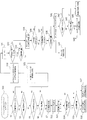
- FIG. 4 shows a determination method for determining the actual short-circuit location by applying the above-described short-circuit abnormality determination method for the MG inverter 5 to the entire drive system including the inverter 7 for the traveling motor and the chopper 8. This will be described with reference to a flowchart.
- the HCU 10 detects any abnormality such as a decrease in input voltage detected by the inverter input voltage sensor 5f or the like while the engine 3 is driven, the MG inverter 5, the travel motor inverter 7 and the chopper All the 8 semiconductor switches 5a, 5b, 7a, 7b, 8b, 8c are turned off, and immediately thereafter, the relay 8f is turned off (S11).
- the power storage device current [I CP ] detected by the chopper current sensor 8e is equal to or greater than a predetermined value [Ib], that is, I CP ⁇ Ib (S14). If it is determined in S14 that I CP is equal to or greater than Ib, that is, if I CP ⁇ Ib (in the case of Yes), the duration [T CP ] in which the state of I CP ⁇ Ib continues is a predetermined time. [Tb] or more, that is, whether or not T CP ⁇ Tb is determined (S15).
- T CP is equal to or greater than Tb as determined in S15, that is, if T CP ⁇ Tb (in the case of Yes), both the input portion of the chopper 8 and the MG inverter 5 including the main smoothing filter 5e are in a short circuit state. (S16). In this case, the drive system becomes unusable.
- I CP is smaller than Ib, that is, I CP ⁇ Ib (in the case of No) by the determination in S14, or if T CP is smaller than Tb, that is, T CP ⁇ Tb.
- T CP is smaller than Tb, that is, T CP ⁇ Tb.
- the relay 8f is turned on in order to detect a short circuit location other than the MG inverter 5 (S31). Thereafter, similarly to S14, it is determined whether or not the power storage device current [I CP ] detected by the chopper current sensor 8e is equal to or greater than a predetermined value [Ib], that is, I CP ⁇ Ib (S32).
- I CP is smaller than Ib, that is, I CP ⁇ Ib (in the case of No) by the determination in S32, or when T CP is smaller than Tb, that is, when T CP ⁇ Tb according to the determination in S33 ( In the case of No), the semiconductor switches 8b and 8c of the chopper 8 are turned on, and control of the input voltage of the power storage device 9 is started (S35). After S35, it is determined whether the input voltage [V MG ] detected by the inverter input voltage sensor 5f is equal to or lower than a predetermined control voltage [Vb], that is, V MG ⁇ Vb (S36).
- the power storage device voltage [V CC ] detected by the power storage device voltage sensor 8h is determined to be a predetermined value determined in S36. It is determined whether or not the value is less than [Vc], that is, whether V CC ⁇ Vc (S37).
- the power storage device voltage [V CC ] is, for example, about 200 to 300 V.
- the duration [T CC ] in which the state of V CC ⁇ Vc continues is determined in advance. It is determined whether or not the predetermined time [Td] or more, that is, T CC ⁇ Td (S38).
- T CC is Td or more, that in the case of T CC ⁇ Td (in the case of Yes)
- the process proceeds to S34, the semiconductor switch 8b of the chopper 8, 8c any one or more of which short-circuited
- the chopper 8 is determined to be unusable due to a short circuit state. Also in this case, the power storage device 9 cannot be used, but there remains a possibility that the MG 4 and the travel motor 6 can be used by turning off the relay 8f and electrically disconnecting the power storage device 9.
- V M is Va or less, that V M in the case of ⁇ Va (in the case of Yes)
- the duration state of V M ⁇ Va continues [T M] is a predetermined time set in advance It is determined whether or not [Te] or more, that is, T M ⁇ Te (S43).
- T M is equal to or greater than Te
- T M ⁇ Te in the case of Yes
- one or more of the semiconductor switches 7a and 7b of the traveling motor inverter 7 are short-circuited,
- the travel motor inverter 7 is determined to be in a short circuit state (S44).
- V M is greater than Va, i.e. the determination in V M> For Va (in the case of No), the or S43, T M is less than Te, that is, when the T M ⁇ Te ( In the case of No), it is determined that the traveling motor inverter 7 has not failed and the semiconductor switches 7a and 7b are not short-circuited (S45). In this case, it is determined that there is no short circuit abnormality in any of the MG inverter 5, the chopper 8, and the travel motor inverter 7.
- the cause is a short circuit abnormality. You can be sure whether it is due to. Further, when the cause of the short circuit abnormality is specified, it is possible to specify which one of the MG inverter 5, the traveling motor inverter 7, and the chopper 8 is short-circuited.
- the HCU 10 stops the driving of the engine 3 via the ECU 3b, whereby the rotational driving of the MG 4 by the engine 3 is stopped, and the motor of the MG 4 accompanying the driving of the engine 3 is stopped.
- the current can be zero.
- FIG. 6 is a schematic configuration diagram showing a drive system for an electric wheel loader according to the second embodiment of the present invention.
- the second embodiment of the present invention differs from the first embodiment described above in that the travel motor 6 in the first embodiment is charged with the power storage device 9 as a drive source by converting energy during travel deceleration into electric power. Therefore, a motor / generator having a power generation function is used.
- symbol is attached
- An electric wheel loader 1A as a work machine includes a load control device 21 that controls driving of the traveling wheels 2a, and the traveling wheels 2a are attached to the MG 4 via the load control device 21. .
- the MG 4 is supplied with electric power from the power storage device 9 when functioning as a traveling motor that rotationally drives the traveling wheels 2a. Then, the load control device 21 receives the driving force from the MG 4 and transmits the rotational force to the traveling wheels 2a.
- the load control device 21 includes an emergency mechanical brake 21a (not shown).
- the rotation of the traveling wheel 2a is transmitted to the MG 4 via the load control device, the MG 4 functions as a generator, and the electromotive force generated by the MG 4 is charged to the power storage device 9 via the MG inverter 5 and the chopper 8.
- the function of the MG4 as a motor or generator is controlled by the HCU 10 through the chopper control circuit 8i, the MG inverter control circuit 5g, and the load control device control circuit 3b based on the accelerator pedal signal and the brake signal described above. It has come to be.
- FIG. 7 is a flowchart for detecting a short-circuit state of the synchronous generator.
- the MG 4 Under the control of the load control device control circuit 3b, the MG inverter control circuit 5g, and the chopper control circuit 8i by the HCU 10, the MG 4 is rotationally driven by the power stored in the power storage device 9, that is, acts as a motor. If any abnormality such as a decrease in the input voltage detected by the inverter input voltage sensor 5f or the like is detected by the HCU 10 in a state of being in the state (for the traveling motor 6), as in the first embodiment. All semiconductor switches 5a, 5b, 8b, and 8c of MG inverter 5 and chopper 8 are turned off, and relay 8f is turned off (S11). The process proceeds to a process for determining a short-circuited location.
- the short-circuit determination of MG4 that is, the procedure up to step S7 is the same as that of the first embodiment, and the description thereof is omitted.
- an input command for emergency mechanical brake 21a is sent from HCU 10 to ECU 3b (S8). That is, in order to stop traveling, an instruction signal for stopping the rotation of MG4 is sent. Then, the rotational drive of MG4 is stopped, and the process proceeds to S13. After the stop of MG4 is completed, relay 8f is turned on.
- the cause when an abnormality is detected in the input voltage of the MG inverter 5 for traveling, as in the first embodiment described above, the cause is caused by a short circuit abnormality. You can be sure whether or not. Furthermore, when the cause is identified as a short circuit abnormality, it is possible to identify which one of the MG inverter 5 and the chopper 8 has a short circuit. Further, when it is determined that MG4 is in a short-circuit state, by stopping traveling using the emergency mechanical brake 21a, the rotational driving of MG4 due to the rotation of the traveling wheel 2a is stopped, and MG4 accompanying the rotational driving of the traveling wheel 2a is stopped. The motor current can be zero.
- the hybrid wheel loader or the electric wheel loader is taken as an example of the work machine, and the mode has been described.
- the present invention is not limited to this, and other devices such as a hydraulic excavator, a forklift, a dump truck, and a crane can be used as long as the energy obtained from the engine 3 or the traveling wheels 2a can be converted into electric power and stored in the power storage device 9.
- This work machine can be used in correspondence.
- a hydraulic pump that drives the front work machine 1b in the case of a hydraulic excavator, various hydraulic pumps and upper swing bodies that drive the front work machine are provided.
- the power storage device 9 only needs to be chargeable / dischargeable, and may be a battery such as a lead storage battery in addition to a capacitor, a lithium ion battery, or the like.
- the semiconductor switches of the MG inverter 5, the traveling motor inverter 7 and the chopper 8 may be switching elements such as other power semiconductor elements instead of the IGBT.
- the MG 4 may be directly coupled to the output shaft 3c of the engine 3, or the MG 4 may be coupled to the output shaft 3c such as a crankshaft of the engine 3 via a belt or gear.
- Hybrid wheel loader (work machine) 1a Car body 1b Front work machine (drive unit) 1c Lift arm 1d Bucket 1e Lift arm cylinder 1f Bucket cylinder 1g Bell crank 2 Traveling part (drive part) 2a Wheel 3 Engine (drive source) 3a Starter 3b ECU 3c Output shaft 4 MG (Permanent magnet type synchronous generator) 4a Rotation sensor 5 MG inverter (inverter) 5a, 5b Semiconductor switch (switching element) 5d Motor current sensor (current detector) 5e Main smoothing capacitor 5f Inverter input voltage sensor (voltage detector) 5g Inverter control circuit 6 Traveling motor (permanent magnet type synchronous generator) 6a Traveling propeller shaft 6b Rotation sensor 7 Traveling motor inverter 7a, 7b Semiconductor switch 7d Motor current sensor 7e Main smoothing capacitor 7f Inverter input voltage sensor 7g Inverter control circuit 8 Chopper 8a Reactor 8b, 8c Semiconductor switch 8e Chopper current sensor 8f
Landscapes
- Engineering & Computer Science (AREA)
- Power Engineering (AREA)
- Transportation (AREA)
- Mechanical Engineering (AREA)
- Life Sciences & Earth Sciences (AREA)
- Sustainable Energy (AREA)
- Sustainable Development (AREA)
- Mining & Mineral Resources (AREA)
- Structural Engineering (AREA)
- General Engineering & Computer Science (AREA)
- Civil Engineering (AREA)
- Hybrid Electric Vehicles (AREA)
- Electric Propulsion And Braking For Vehicles (AREA)
- Control Of Eletrric Generators (AREA)
- Operation Control Of Excavators (AREA)
- Control Of Electric Motors In General (AREA)
- Control Of Ac Motors In General (AREA)
Abstract
Description
以下、本発明に係る作業機械の第1実施形態として、ハイブリッド式ホイールローダ1を例に挙げて説明する。
図1に示すように、ハイブリッド式ホイールローダ1は、走行部2を電動化した駆動システムを備えた走行電動駆動式ホイールローダであって、いわゆるシリーズ型のハイブリッドシステムが搭載されたハイブリッド建設車両である。なお、本発明に係るハイブリッド式の作業機械としては、油圧駆動をアシストするものの他、別の電動モータによる駆動をアシストするものも含まれる。
図6は、本発明の第2実施形態に係る電動ホイールローダの駆動システムを示す概略構成図である。
1a 車体
1b フロント作業機(駆動部)
1c リフトアーム
1d バケット
1e リフトアームシリンダ
1f バケットシリンダ
1g ベルクランク
2 走行部(駆動部)
2a 走行輪
3 エンジン(駆動源)
3a スタータ
3b ECU
3c 出力軸
4 MG(永久磁石式の同期発電機)
4a 回転センサ
5 MG用インバータ(インバータ)
5a,5b 半導体スイッチ(スイッチング素子)
5d モータ電流センサ(電流検出部)
5e 主平滑コンデンサ
5f インバータ入力電圧センサ(電圧検出部)
5g インバータ制御回路
6 走行モータ(永久磁石式の同期発電機)
6a 走行用プロペラシャフト
6b 回転センサ
7 走行モータ用インバータ
7a,7b 半導体スイッチ
7d モータ電流センサ
7e 主平滑コンデンサ
7f インバータ入力電圧センサ
7g インバータ制御回路
8 チョッパ
8a リアクトル
8b,8c 半導体スイッチ
8e チョッパ電流センサ
8f リレー
8g 電圧センサ
8h 蓄電装置電圧センサ
8i チョッパ制御回路
9 蓄電装置(駆動源)
10 HCU(制御部)
21 負荷制御装置
A 起動信号
B アクセル信号
C CAN信号
D 負荷制動出力信号
Claims (3)
- 駆動源と、
この駆動源によって駆動する永久磁石式の同期発電機と、
前記同期発電機によって発生した電力によって駆動される駆動部と、
前記同期発電機に流れる電流を検出する電流検出部およびスイッチング素子を有するインバータと、
前記同期発電機の電気的な異常を検出する制御部と、を備え、
前記制御部は、前記同期発電機の電気的な異常を検出した際に、前記インバータのスイッチング素子のゲートをオフし、この状態で前記電流検出部により所定値以上の電流が所定時間以上継続して検出された場合に、前記インバータが短絡状態にあると判断することを特徴とする作業機械。 - 請求項1記載の作業機械において、
前記同期発電機の回転数を検出する回転数検出装置と、
前記インバータに入力される入力電圧を検出する電圧検出部とを備え、
前記制御部は、前記回転数検出装置からの回転数信号及び前記電圧検出部からの電圧信号を入力し、前記電圧検出部にて検出された入力電圧が所定電圧値以下であって、かつ、前記回転数検出装置によって検出された同期発電機の回転数が正常時における前記所定電圧値に相応する回転数以上のときに、前記同期発電機に電気的な異常が生じたと判断する
ことを特徴とする作業機械。 - 請求項1記載の作業機械において、
前記駆動部から回生されるエネルギにて前記同期発電機を駆動し、この同期発電機から前記インバータを介して出力される電力にて蓄電される蓄電装置を備えたことを特徴とする作業機械。
Priority Applications (4)
| Application Number | Priority Date | Filing Date | Title |
|---|---|---|---|
| EP15764694.4A EP3121958B1 (en) | 2014-03-18 | 2015-02-27 | Working machine |
| US14/915,736 US9828749B2 (en) | 2014-03-18 | 2015-02-27 | Working machine |
| JP2016508647A JP6173564B2 (ja) | 2014-03-18 | 2015-02-27 | 作業機械 |
| CN201580001789.5A CN105517837B (zh) | 2014-03-18 | 2015-02-27 | 作业机械 |
Applications Claiming Priority (2)
| Application Number | Priority Date | Filing Date | Title |
|---|---|---|---|
| JP2014055576 | 2014-03-18 | ||
| JP2014-055576 | 2014-03-18 |
Publications (1)
| Publication Number | Publication Date |
|---|---|
| WO2015141449A1 true WO2015141449A1 (ja) | 2015-09-24 |
Family
ID=54144424
Family Applications (1)
| Application Number | Title | Priority Date | Filing Date |
|---|---|---|---|
| PCT/JP2015/055943 Ceased WO2015141449A1 (ja) | 2014-03-18 | 2015-02-27 | 作業機械 |
Country Status (5)
| Country | Link |
|---|---|
| US (1) | US9828749B2 (ja) |
| EP (1) | EP3121958B1 (ja) |
| JP (1) | JP6173564B2 (ja) |
| CN (1) | CN105517837B (ja) |
| WO (1) | WO2015141449A1 (ja) |
Cited By (2)
| Publication number | Priority date | Publication date | Assignee | Title |
|---|---|---|---|---|
| JP2017139930A (ja) * | 2016-02-05 | 2017-08-10 | 住友重機械工業株式会社 | 動力発生装置およびそれを用いたショベル |
| JP2017163660A (ja) * | 2016-03-08 | 2017-09-14 | Ntn株式会社 | 風力発電システム |
Families Citing this family (7)
| Publication number | Priority date | Publication date | Assignee | Title |
|---|---|---|---|---|
| JP6173564B2 (ja) * | 2014-03-18 | 2017-08-02 | 日立建機株式会社 | 作業機械 |
| CN106223393B (zh) * | 2016-09-18 | 2019-04-05 | 唐忠盛 | 一种数字化电动液压挖掘机 |
| JP6773599B2 (ja) * | 2017-04-14 | 2020-10-21 | 日立建機株式会社 | 蓄電装置コントローラ及び電動システム並びに建設機械 |
| JP6984390B2 (ja) * | 2017-12-20 | 2021-12-17 | 株式会社デンソー | 電力制御ユニット |
| JP2020162254A (ja) * | 2019-03-26 | 2020-10-01 | 日本電産株式会社 | インバータ装置 |
| KR102727990B1 (ko) * | 2020-04-14 | 2024-11-07 | 현대자동차주식회사 | 차량용 충전시스템 및 이의 배터리 충전 중지 방법 |
| JP7666153B2 (ja) * | 2021-06-17 | 2025-04-22 | コベルコ建機株式会社 | 電動作業機械 |
Citations (4)
| Publication number | Priority date | Publication date | Assignee | Title |
|---|---|---|---|---|
| JPH05176478A (ja) * | 1991-12-25 | 1993-07-13 | Mazda Motor Corp | オルタネータ制御装置 |
| JP2006121844A (ja) * | 2004-10-22 | 2006-05-11 | Toyota Motor Corp | 交流電源装置 |
| JP2009142053A (ja) * | 2007-12-06 | 2009-06-25 | Toyota Motor Corp | インバータの短絡素子判定装置 |
| JP2010222815A (ja) * | 2009-03-23 | 2010-10-07 | Sumitomo Heavy Ind Ltd | ハイブリッド型建設機械 |
Family Cites Families (12)
| Publication number | Priority date | Publication date | Assignee | Title |
|---|---|---|---|---|
| EP1751862B1 (en) * | 2004-04-26 | 2014-07-23 | LeTourneau Technologies Drilling Systems, Inc. | Adaptive gate drive for switching devices of inverter |
| US8036008B2 (en) * | 2006-09-15 | 2011-10-11 | Mitsubishi Electric Corporation | DC/DC power converting apparatus |
| JP4438833B2 (ja) | 2007-07-04 | 2010-03-24 | トヨタ自動車株式会社 | 電力変換装置の異常検出装置および異常検出方法 |
| JP2009201194A (ja) * | 2008-02-19 | 2009-09-03 | Toyota Motor Corp | 回転電機の異常検出装置および異常検出方法 |
| KR101482481B1 (ko) * | 2008-11-18 | 2015-01-15 | 스미도모쥬기가이고교 가부시키가이샤 | 작업기계 |
| JP4968698B2 (ja) * | 2008-12-26 | 2012-07-04 | 本田技研工業株式会社 | 電動機の制御装置 |
| JP5201245B2 (ja) * | 2010-09-17 | 2013-06-05 | 株式会社デンソー | 回転機の制御装置 |
| CN103250339B (zh) * | 2010-12-07 | 2015-11-25 | 日立汽车系统株式会社 | 电力变换装置 |
| JP5290345B2 (ja) * | 2011-03-31 | 2013-09-18 | 株式会社小松製作所 | 発電電動機および作業機械 |
| EP2733843B1 (en) * | 2011-07-12 | 2017-08-23 | Toyota Jidosha Kabushiki Kaisha | Vehicle and vehicle control method |
| JP5925079B2 (ja) * | 2012-07-31 | 2016-05-25 | 日立オートモティブシステムズ株式会社 | モータ制御装置 |
| JP6173564B2 (ja) * | 2014-03-18 | 2017-08-02 | 日立建機株式会社 | 作業機械 |
-
2015
- 2015-02-27 JP JP2016508647A patent/JP6173564B2/ja not_active Expired - Fee Related
- 2015-02-27 WO PCT/JP2015/055943 patent/WO2015141449A1/ja not_active Ceased
- 2015-02-27 EP EP15764694.4A patent/EP3121958B1/en not_active Not-in-force
- 2015-02-27 US US14/915,736 patent/US9828749B2/en not_active Expired - Fee Related
- 2015-02-27 CN CN201580001789.5A patent/CN105517837B/zh not_active Expired - Fee Related
Patent Citations (4)
| Publication number | Priority date | Publication date | Assignee | Title |
|---|---|---|---|---|
| JPH05176478A (ja) * | 1991-12-25 | 1993-07-13 | Mazda Motor Corp | オルタネータ制御装置 |
| JP2006121844A (ja) * | 2004-10-22 | 2006-05-11 | Toyota Motor Corp | 交流電源装置 |
| JP2009142053A (ja) * | 2007-12-06 | 2009-06-25 | Toyota Motor Corp | インバータの短絡素子判定装置 |
| JP2010222815A (ja) * | 2009-03-23 | 2010-10-07 | Sumitomo Heavy Ind Ltd | ハイブリッド型建設機械 |
Non-Patent Citations (1)
| Title |
|---|
| See also references of EP3121958A4 * |
Cited By (2)
| Publication number | Priority date | Publication date | Assignee | Title |
|---|---|---|---|---|
| JP2017139930A (ja) * | 2016-02-05 | 2017-08-10 | 住友重機械工業株式会社 | 動力発生装置およびそれを用いたショベル |
| JP2017163660A (ja) * | 2016-03-08 | 2017-09-14 | Ntn株式会社 | 風力発電システム |
Also Published As
| Publication number | Publication date |
|---|---|
| EP3121958A1 (en) | 2017-01-25 |
| CN105517837B (zh) | 2017-08-15 |
| EP3121958B1 (en) | 2021-11-03 |
| JP6173564B2 (ja) | 2017-08-02 |
| EP3121958A4 (en) | 2017-11-29 |
| JPWO2015141449A1 (ja) | 2017-04-06 |
| CN105517837A (zh) | 2016-04-20 |
| US9828749B2 (en) | 2017-11-28 |
| US20160194855A1 (en) | 2016-07-07 |
Similar Documents
| Publication | Publication Date | Title |
|---|---|---|
| JP6173564B2 (ja) | 作業機械 | |
| EP2181905B1 (en) | Hybrid working machine | |
| JP5149826B2 (ja) | ハイブリッド式作業機械及びサーボ制御システム | |
| JP5265754B2 (ja) | ハイブリッド型ショベル | |
| KR101686004B1 (ko) | 하이브리드 작업 기계 및 하이브리드 작업 기계의 제어 방법 | |
| WO2010087363A1 (ja) | ハイブリッド型作業機械及び蓄電制御装置 | |
| JP4949288B2 (ja) | ハイブリッド型建設機械 | |
| JP5421074B2 (ja) | ハイブリッド型建設機械 | |
| CN104838580A (zh) | 混合动力作业机械 | |
| JP5674086B2 (ja) | ハイブリッド型建設機械 | |
| JP5583901B2 (ja) | ハイブリッド型建設機械 | |
| JP7683169B2 (ja) | 作業機械 | |
| US9007003B2 (en) | Method for controlling an inverter for driving a swing motor | |
| JP5307692B2 (ja) | リフティングマグネット式自走機械 | |
| JP5178666B2 (ja) | ハイブリッド型掘削機械 | |
| JP5122548B2 (ja) | ハイブリッド型建設機械 | |
| JP5449806B2 (ja) | ハイブリッド型作業機械及びその制御方法 | |
| JP5037558B2 (ja) | ハイブリッド型建設機械 | |
| JP6900112B2 (ja) | 作業機械 | |
| JP2016014264A (ja) | ハイブリッド式作業機械 | |
| JP2014231297A (ja) | ハイブリッド作業機械 |
Legal Events
| Date | Code | Title | Description |
|---|---|---|---|
| 121 | Ep: the epo has been informed by wipo that ep was designated in this application |
Ref document number: 15764694 Country of ref document: EP Kind code of ref document: A1 |
|
| ENP | Entry into the national phase |
Ref document number: 2016508647 Country of ref document: JP Kind code of ref document: A |
|
| REEP | Request for entry into the european phase |
Ref document number: 2015764694 Country of ref document: EP |
|
| WWE | Wipo information: entry into national phase |
Ref document number: 2015764694 Country of ref document: EP |
|
| WWE | Wipo information: entry into national phase |
Ref document number: 14915736 Country of ref document: US |
|
| NENP | Non-entry into the national phase |
Ref country code: DE |