WO2015141837A1 - 車両用シート - Google Patents
車両用シート Download PDFInfo
- Publication number
- WO2015141837A1 WO2015141837A1 PCT/JP2015/058520 JP2015058520W WO2015141837A1 WO 2015141837 A1 WO2015141837 A1 WO 2015141837A1 JP 2015058520 W JP2015058520 W JP 2015058520W WO 2015141837 A1 WO2015141837 A1 WO 2015141837A1
- Authority
- WO
- WIPO (PCT)
- Prior art keywords
- vehicle seat
- seat
- rotation mechanism
- escape
- stitching
- Prior art date
- Legal status (The legal status is an assumption and is not a legal conclusion. Google has not performed a legal analysis and makes no representation as to the accuracy of the status listed.)
- Ceased
Links
Images


Classifications
-
- B—PERFORMING OPERATIONS; TRANSPORTING
- B60—VEHICLES IN GENERAL
- B60N—SEATS SPECIALLY ADAPTED FOR VEHICLES; VEHICLE PASSENGER ACCOMMODATION NOT OTHERWISE PROVIDED FOR
- B60N2/00—Seats specially adapted for vehicles; Arrangement or mounting of seats in vehicles
- B60N2/24—Seats specially adapted for vehicles; Arrangement or mounting of seats in vehicles for particular purposes or particular vehicles
- B60N2/38—Seats specially adapted for vehicles; Arrangement or mounting of seats in vehicles for particular purposes or particular vehicles specially constructed for use on tractors or like off-road vehicles
- B60N2/40—Seats specially adapted for vehicles; Arrangement or mounting of seats in vehicles for particular purposes or particular vehicles specially constructed for use on tractors or like off-road vehicles saddle type
-
- B—PERFORMING OPERATIONS; TRANSPORTING
- B62—LAND VEHICLES FOR TRAVELLING OTHERWISE THAN ON RAILS
- B62J—CYCLE SADDLES OR SEATS; AUXILIARY DEVICES OR ACCESSORIES SPECIALLY ADAPTED TO CYCLES AND NOT OTHERWISE PROVIDED FOR, e.g. ARTICLE CARRIERS OR CYCLE PROTECTORS
- B62J1/00—Saddles or other seats for cycles; Arrangement thereof; Component parts
- B62J1/12—Box-shaped seats; Bench-type seats, e.g. dual or twin seats
-
- B—PERFORMING OPERATIONS; TRANSPORTING
- B62—LAND VEHICLES FOR TRAVELLING OTHERWISE THAN ON RAILS
- B62J—CYCLE SADDLES OR SEATS; AUXILIARY DEVICES OR ACCESSORIES SPECIALLY ADAPTED TO CYCLES AND NOT OTHERWISE PROVIDED FOR, e.g. ARTICLE CARRIERS OR CYCLE PROTECTORS
- B62J1/00—Saddles or other seats for cycles; Arrangement thereof; Component parts
- B62J1/14—Separate pillions
-
- B—PERFORMING OPERATIONS; TRANSPORTING
- B62—LAND VEHICLES FOR TRAVELLING OTHERWISE THAN ON RAILS
- B62J—CYCLE SADDLES OR SEATS; AUXILIARY DEVICES OR ACCESSORIES SPECIALLY ADAPTED TO CYCLES AND NOT OTHERWISE PROVIDED FOR, e.g. ARTICLE CARRIERS OR CYCLE PROTECTORS
- B62J1/00—Saddles or other seats for cycles; Arrangement thereof; Component parts
- B62J1/18—Covers for saddles or other seats; Paddings
- B62J1/20—Detachable covers; Detachable pads
-
- B—PERFORMING OPERATIONS; TRANSPORTING
- B62—LAND VEHICLES FOR TRAVELLING OTHERWISE THAN ON RAILS
- B62J—CYCLE SADDLES OR SEATS; AUXILIARY DEVICES OR ACCESSORIES SPECIALLY ADAPTED TO CYCLES AND NOT OTHERWISE PROVIDED FOR, e.g. ARTICLE CARRIERS OR CYCLE PROTECTORS
- B62J1/00—Saddles or other seats for cycles; Arrangement thereof; Component parts
- B62J1/28—Other additional equipment, e.g. back-rests for children
Definitions
- the present invention relates to a vehicle seat, and more particularly, to a vehicle seat suitable for a straddle-type seat for two- or three-wheeled vehicles that can move between a flip-up state and a seating state by moving the rear side.
- Patent Document 1 a technique has been known in which a vehicle seat can be switched between a seating state and a flip-up state via a rotation mechanism such as a hinge mechanism.
- the “side portion” means a seat outer peripheral portion excluding a seating portion, and is used as an expression including front and rear side portions and left and right side portions.
- a two- or three-wheeled vehicle seat that does not interfere with the side portion even when the rotation mechanism changes, such as the shape and size of the rotation mechanism, is desired.
- An object of the present invention is a vehicle seat that can be switched between a flip-up state and a seated state by a turning mechanism, and is suitable for a straddle-type seat for a two- or three-wheeled vehicle that does not cause interference between the turning mechanism and the seat.
- the object is to provide a vehicle seat.
- the subject includes a bottom plate, a seating portion, and a side portion, and in the vehicle seat formed by covering the seating portion and the side portion with a skin material,
- the vehicle seat can be switched between a sitting state and a flip-up state via a rotation mechanism, and a relief portion of the rotation mechanism is provided on the side portion facing the rotation mechanism. It is solved by.
- the escape portion since the escape portion is formed, the escape portion can suppress an increase in the size of the seat while suppressing interference between the side portion and the rotation mechanism.
- the escape portion is a notch portion formed by notching the bottom plate.
- the escape portion is formed by a notch, and only the notch is formed, so the configuration of the escape portion is simple.
- the escape portion is more preferably a cutout portion cut out in an arc shape. As described above, when the arc-shaped cutout portion is used, it is possible to suppress a reduction in rigidity of the side portion, that is, the outer peripheral portion of the seat.
- the outside of the escape portion is covered with a cover member.
- a cover member By covering with the cover member, intrusion of foreign matter can be suppressed via the escape portion.
- the cutout portion has an arc shape in this way, when the skin is attached along the cutout, the work of attaching the skin becomes easier and wrinkles and the like are reduced as compared with the rectangular cutout.
- an extension part is provided on the cover member and the extension part is attached to the inner surface of the side part.
- the cover member can be stably attached.
- the escape portion can suppress the increase in size of the seat while suppressing the interference between the side portion and the rotation mechanism. Further, since the escape portion is formed by a notch and only the notch is formed, the configuration of the escape portion is simple. Further, when the arc-shaped cutout portion is used, it is possible to suppress a decrease in rigidity of the side portion, that is, the seat outer peripheral portion. By covering with the cover member, the intrusion of foreign matter can be suppressed through the escape portion. Since the notch has an arc shape, when the skin is attached along the notch, the work of attaching the skin becomes easier and wrinkles and the like are reduced as compared to the rectangular notch. When the extension portion is attached to the inner surface of the side portion, the cover member can be stably attached.
- FIG. 4 is a partially enlarged explanatory view of FIG. 3. It is the perspective view made into the seating state. It is a perspective view of a flip-up state. It is explanatory drawing by the side of the back surface of the state which attached the cover of the straddle-type seat for two and three-wheeled vehicles of the flip-up state.
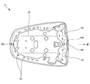
- the straddle-type seat S for two- and three-wheeled vehicles includes a bottom plate 10, a seating portion 20, and a side portion 30.
- the “side portion 30” in this specification refers to the seat outer peripheral portion excluding the seating portion 20, and is used as an expression including the front and rear side portions and the left and right side portions.
- the symbol Sf in the drawings shown in the present embodiment is a front seat, and the symbol B is a belt.
- the straddle-type seat S for two- and three-wheeled vehicles has the cushion K placed on the bottom plate 10 and covered with the skin material H. More specifically, the cushion K is covered with the skin material H, the side portion 30 of the bottom plate 10 is wrapped, and the end portion of the skin material H is connected to the back side surface (the surface side facing the vehicle body) of the bottom plate 10.
- the staple 40 is driven in and attached with a mounting tool such as a tucker at the position of the outer periphery of.
- the upper surface side is the seating portion 20, and the side portion side of the seating portion 20 is formed as the side portion 30.
- the skin material H is composed of a large format portion H1, a side gusset H2, and a middle-prevention cover H3.
- the large format portion H1 is previously formed into a predetermined shape according to the seat shape of the straddle-type seat S for two- and three-wheeled vehicles.
- the side gusset H2 is made of non-molded Woolley nylon which is not molded, and the anti-glare cover H3 is made of non-molded Woolley nylon.
- the large format part H1, the side gusset H2, and the middle appearance prevention cover H3 are formed of the same material, a sense of unity of the skin material H can be ensured.
- the intermediate appearance prevention cover H3 covers the outer side of a notch that is an escape portion 70 described later to improve the appearance.
- the same thickness is used for the large-size portion H1 and the side gusset H2 of the skin material H, and the thickness of the intermediate prevention cover H3 is smaller than the thickness of the large-size portion H1 and the side gusset H2. .
- the medium-color prevention cover H ⁇ b> 3 of the present embodiment is sewn with a large line portion H ⁇ b> 1 that covers the seating portion 20 and a stitching line 50 at the front position of the seating portion 20, The portion 30 is covered.
- the stitching line 50 is configured so as to be covered and not visible from the exterior by disposing the belt B described above. For this reason, combined with the large format portion H1, the side gusset H2, and the middle-visible prevention cover H3 made of the same material, the unity as the skin material H is secured.
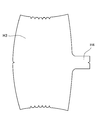
- FIG. 11 illustrates a stitching method corresponding to the section aa in FIG. 1.
- three large format portions H1, side gussets H2, and a medium-visible prevention cover H3 are attached to the first stitched portion 51.
- the large-sized portion H1 and the middle-image preventing cover H3 are temporarily stitched by the second stitching portion 52.
- a portion (removal portion 54) below the first stitching portion 51 of the side gusset H2 located on the inside appearance prevention cover H3 side is cut.
- the three large stitch portions H1, the side gusset H2, and the middle-visible prevention cover H3 are simultaneously stitched by the third stitching portion 53 with a single stitch.
- the third stitching portion 53 in a single stitch becomes four layers of the epidermis, and unevenness is likely to occur in the appearance.
- the stitching portion (removal portion 54) of the side gusset H2 is cut by one after the stitching at the first stitching portion 51, the outer appearance is obtained when the stitching is performed at the third stitching portion 53. As a result, it is possible to prevent the appearance from being affected.
- FIG. 10 is an explanatory view of the fixing skin H4.
- This fixing skin H4 suppresses the flickering of the anti-smearing cover H3, and is integrated with the anti-smearing cover H3 as a cover member on the end side. It is formed as an extending part extending from the center position (center).
- the fixing skin H4 is fixed to the bottom plate 10 by a staple 40.
- the bottom plate 10 of the present embodiment is made of a single plate made of resin (for example, PP; polypropylene, etc.), and a bead, an uneven portion, etc. for improving strength are appropriately formed at a predetermined location.
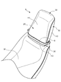
- a rotation mechanism 60 to be described later is attached to a position on the front side facing the vehicle side, and a connecting portion 80 (see FIG. 5) detachably connected to the vehicle body side on a position on the rear side facing the vehicle body side. 3) is formed.
- the connecting portion 80 is a gate-type engaging portion and is detachably formed by a catch portion (not shown) on the vehicle body side.
- a front side portion which is the side portion 30 of the bottom plate 10 is a cutout portion formed by cutting out the bottom plate 10 in order to form the relief portion 70.
- the cutout portion of the present embodiment is cut out in an arc shape, and the arcuate cutout portion forms an escape portion 70.
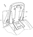
- FIG. 8 is an explanatory view on the back side in a state in which the cover 90 of the straddle-type seat S for two- and three-wheeled vehicles in a flip-up state is attached
- FIG. 9 is an explanatory view on the back side in a state in which the cover 90 in FIG. .
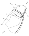
- the two- or three-wheeled vehicle seat S which is a vehicle seat, can be switched between a sitting state and a flip-up state via the rotation mechanism 60.
- the front side portion 30 facing the rotation mechanism 60 is provided with a relief portion 70 of the rotation mechanism 60.
- the relief portion 70 covers the notch portion in which the bottom plate 10 is notched along the side gusset H2, and when the notch portion that is the relief portion 70 is arcuate, When attaching the skin (side gusset H2) along the notch, it is easier to attach the skin and reduce wrinkles as compared to the rectangular notch.
- the cover prevention member H3 that is a cover member, even if the front side portion 30 that is in the seating state is exposed, the escape portion is not exposed to the appearance, and the appearance is good. Become.
Landscapes
- Engineering & Computer Science (AREA)
- Mechanical Engineering (AREA)
- Aviation & Aerospace Engineering (AREA)
- Transportation (AREA)
- Seats For Vehicles (AREA)
Abstract
回動機構によって、跳ね上げ状態と着座状態とを切り替えが可能な車両用シートにおいて、回動機構とシートとの干渉が生じない二・三輪車用跨座式シートに好適な車両用シートを提供する。本発明の車両用シート(S)は、ボトムプレート(10)と、着座部(20)と、サイド部(30)と、を有するものである。そして、表皮材(H)で着座部(20)及びサイド部(30)を被覆している。この車両用シート(S)には、回動機構(60)を介して、着座状態と跳ね上げ状態に切り替え可能であって、回動機構(60)と相対するサイド部(30)に回動機構の逃げ部(70)を設けている。
Description
本発明は車両用シートに係り、特に、後部側が可動して跳ね上げ状態と着座状態とを切り替えが可能な二・三輪車用跨座式シートに好適な車両用シートに関する。
従来から車両用シートについて、ヒンジ機構などの回動機構を介して、着座状態と跳ね上げ状態に切り替え可能になっている技術は知られている(特許文献1)。
回動機構の形状や大きさによっては、車両用シートの回動機構とシート、例えばシート外周部であるサイド部などが干渉する虞が生じる場合がある。なお、本明細書における「サイド部」とは着座部を除くシート外周部をいい、前後の側部、左右の側部を含んだ表現として用いる。
回動機構の形状や大きさなど、回動機構が変わっても、サイド部などが干渉する虞のない二・三輪車用シートが望まれている。
本発明の目的は、回動機構によって、跳ね上げ状態と着座状態とを切り替えが可能な車両用シートにおいて、回動機構とシートとの干渉が生じない二・三輪車用跨座式シートに好適な車両用シートを提供することにある。
前記課題は、本発明の車両用シートによれば、ボトムプレートと、着座部と、サイド部と、を有し、表皮材で前記着座部及び前記サイド部を被覆してなる車両用シートにおいて、前記車両用シートには、回動機構を介して、着座状態と跳ね上げ状態に切り替え可能であって、前記回動機構と相対する前記サイド部に前記回動機構の逃げ部を設けたこと、により解決される。
このように、逃げ部が形成されているので、この逃げ部によって、サイド部と回動機構との干渉を抑制しつつ、シートの大型化を抑制できる。
このように、逃げ部が形成されているので、この逃げ部によって、サイド部と回動機構との干渉を抑制しつつ、シートの大型化を抑制できる。
このとき、前記逃げ部は、前記ボトムプレートを切り欠いて形成した切欠き部であると好適である。
このように、逃げ部を切欠き部で形成しており、切り欠くだけであるので逃げ部の構成が簡単である。
このように、逃げ部を切欠き部で形成しており、切り欠くだけであるので逃げ部の構成が簡単である。
また前記逃げ部は、円弧状に切り欠いた切欠き部であるとより好適である。
このように、円弧状の切欠き部にすると、サイド部、つまりシート外周部の剛性低下を抑制できる。
このように、円弧状の切欠き部にすると、サイド部、つまりシート外周部の剛性低下を抑制できる。
そして、前記逃げ部の外側をカバー部材で覆って構成すると好適である。
このように、カバー部材で覆うことにより、逃げ部を介して異物の侵入を抑制できる。
このように、カバー部材で覆うことにより、逃げ部を介して異物の侵入を抑制できる。
さらに、前記切欠き部に沿わせて表皮を取り付けると好適である。
このように切欠き部が円弧状であるので、切欠きに沿わせて表皮を取付けるときに、四角形状の切欠きに比べて、表皮の取付け作業が容易になり、シワなども少なくなる。
このように切欠き部が円弧状であるので、切欠きに沿わせて表皮を取付けるときに、四角形状の切欠きに比べて、表皮の取付け作業が容易になり、シワなども少なくなる。
また、前記カバー部材に延出部を設け、該延出部を前記サイド部の内面に取り付けると好適である。このように延出部をサイド部の内面に取り付けると、カバー部材の安定した取付けが出来る。
本発明によれば、逃げ部によって、サイド部と回動機構との干渉を抑制しつつ、シートの大型化を抑制できる。また逃げ部を切欠き部で形成しており、切り欠くだけであるので逃げ部の構成が簡単である。
また、円弧状の切欠き部にすると、サイド部、つまりシート外周部の剛性低下を抑制できる。カバー部材で覆うことにより、逃げ部を介して異物の侵入を抑制できる。
欠き部が円弧状であるので、切欠きに沿わせて表皮を取付けるときに、四角形状の切欠きに比べて、表皮の取付け作業が容易になり、シワなども少なくなる。そして延出部をサイド部の内面に取り付けると、カバー部材の安定した取付けが出来る。
また、円弧状の切欠き部にすると、サイド部、つまりシート外周部の剛性低下を抑制できる。カバー部材で覆うことにより、逃げ部を介して異物の侵入を抑制できる。
欠き部が円弧状であるので、切欠きに沿わせて表皮を取付けるときに、四角形状の切欠きに比べて、表皮の取付け作業が容易になり、シワなども少なくなる。そして延出部をサイド部の内面に取り付けると、カバー部材の安定した取付けが出来る。
以下、本発明の一実施形態を図面に基づいて説明する。なお、以下に説明する部材,配置等は本発明を限定するものでなく、本発明の趣旨の範囲内で種々改変することができるものである。
本実施形態では、車両用シートとして、二・三輪車用跨座式シートを例にして説明する。本実施形態の二・三輪車用跨座式シートSは、ボトムプレート10と、着座部20と、サイド部30と、を有している。なお前述したように、本明細書において「サイド部30」とは着座部20を除くシート外周部をいい、前後の側部、左右の側部を含んだ表現として用いている。また本実施形態で示す図中の記号Sfは前席用のシートであり、記号Bはベルトである。
そして、二・三輪車用跨座式シートSは、ボトムプレート10に、クッションKを載置して、表皮材HでクッションKを被覆している。より具体的には、表皮材HでクッションKを被覆して、ボトムプレート10のサイド部30を巻き込んで、表皮材Hの端末部を、ボトムプレート10の裏側面(車体と対向する面側)の外周の位置で、タッカー等の取着具でステイプル40を打ち込んで取り付けている。このようにして、上面側が着座部20となっており、この着座部20の側部側はサイド部30として形成されている。
表皮材Hは、大判部H1と、サイドマチH2と、中見え防止カバーH3とから構成されており、大判部H1は二・三輪車用跨座式シートSのシート形状に合わせて予め所定形状に成形された成形用ウーリーナイロンで構成し、サイドマチH2は成形されていない非成形ウーリーナイロンで構成し、中見え防止カバーH3は成形されていない非成形ウーリーナイロンで構成している。このように本実施形態では、大判部H1とサイドマチH2と中見え防止カバーH3とが同じ素材で形成されているので、表皮材Hの一体感を確保することができる。また中見え防止カバーH3は、後述する逃げ部70である切欠き部の外側を覆って外観を良好にするものである。
本実施形態では、表皮材Hの大判部H1及びサイドマチH2の厚さは同じものを用いており、中見え防止カバーH3の厚さは大判部H1及びサイドマチH2の厚さより薄いものを用いている。
本実施形態では、表皮材Hの大判部H1及びサイドマチH2の厚さは同じものを用いており、中見え防止カバーH3の厚さは大判部H1及びサイドマチH2の厚さより薄いものを用いている。
本実施形態の中見え防止カバーH3は、図1で示すように、着座部20の前方位置で、着座部20を被覆する大判部H1と縫合ライン50で縫合されて、前側の側部のサイド部30を被覆するものである。なお、この縫合ライン50は、前述したベルトBを配置することにより、覆われて外観から見えないように構成されている。このため、大判部H1とサイドマチH2と中見え防止カバーH3が同一素材で形成されているのと相俟って、表皮材Hとしての一体感を確保している。
この表皮材Hの着座部20とサイド部30との縫合は、図11の(A)~(C)で示すように大判部H1とサイドマチH2と中見え防止カバーH3の縫合により行われる。すなわち、図11は図1のa-a断面に相当する縫合方法を説明するものであるが、先ず、大判部H1と、サイドマチH2と、中見え防止カバーH3の三枚を第1縫合部51で合わせ縫いを行う。次に、大判部H1と中見え防止カバーH3とを第2縫合部52で仮縫いする。そして、中見え防止カバーH3側に位置するサイドマチH2の第1縫合部51より下側の部分(切除部54)を切断する。そして、大判部H1とサイドマチH2、中見え防止カバーH3の三枚を第3縫合部53で同時にシングルステッチ縫製する。
このように、サイドマチH2の一部を切除部54でカットすると、通常であれば、シングルステッチでの第3縫合部53が表皮の4枚重ねになってしまい、外観に凹凸が発生しやすくなるが、本実施形態のように、第1縫合部51での合わせ縫い後に、サイドマチH2の縫い代部分(切除部54)を1枚カットすることにより、第3縫合部53で縫合したときに、外観に凹凸がでないようにして、外観に影響を及ぼさないようにできる。
図10は、固定用表皮H4の説明図であるが、この固定用表皮H4は中見え防止カバーH3のバタツキを抑えるものであり、カバー部材としての中見え防止カバーH3と一体で端部側の中心位置(センター)から延出する延出部として形成されている。そして、固定用表皮H4は、ステイプル40によってボトムプレート10に固定されている。
本実施形態のボトムプレート10は樹脂製(例えばPP;ポリプロピレンなど)の一枚の板体から構成されており、所定箇所に強度向上のためのビード、凹凸部などが適宜形成されており、車体側と対向する前方側の位置には、後述する回動機構60が取付けられるものであり、車体側と対向する後方側の位置には、車体側と着脱可能に連結される連結部80(図3参照)が形成されている。連結部80は門型の係合部で車体側のキャッチ部(不図示)などによって着脱可能に形成されている。
またボトムプレート10のサイド部30である前側の側部には、逃げ部70を形成するためボトムプレート10を切り欠いて形成した切欠き部となっている。
本実施形態の切欠き部は、円弧状に切り欠いたもので、この円弧状の切欠き部が逃げ部70を形成している。
またボトムプレート10のサイド部30である前側の側部には、逃げ部70を形成するためボトムプレート10を切り欠いて形成した切欠き部となっている。
本実施形態の切欠き部は、円弧状に切り欠いたもので、この円弧状の切欠き部が逃げ部70を形成している。
図8は跳ね上げ状態の二・三輪車用跨座式シートSのカバー90を取り付けた状態の裏面側の説明図、図9は図8のカバー90を取り外した状態の裏面側の説明図である。これらの図では回動機構の詳細は省略している。そして、車両用シートである二・三輪車用跨座式シートSは、回動機構60を介して、着座状態と跳ね上げ状態に切り替え可能となっている。
そして、回動機構60と相対する前側のサイド部30には、回動機構60の逃げ部70が設けられている。この逃げ部70は前述したように、ボトムプレート10を切り欠いた切欠き部にサイドマチH2を沿わせて被覆しており、この逃げ部70である切欠き部が円弧状の場合には、切欠きに沿わせて、表皮(サイドマチH2)を取付けるときに、四角形状の切欠きに比べて、表皮の取付け作業が容易になり、シワなども少なくなる。
そして、逃げ部の外側をカバー部材である中見え防止カバーH3で覆っているので、着座状態となる前側のサイド部30が露見しても、外観に逃げ部が露見しないで、外観が良好となる。
そして、逃げ部の外側をカバー部材である中見え防止カバーH3で覆っているので、着座状態となる前側のサイド部30が露見しても、外観に逃げ部が露見しないで、外観が良好となる。
10 ボトムプレート
20 着座部
30 サイド部
40 ステイプル
50 縫合ライン
51 第1縫合部
52 第2縫合部
53 第3縫合部
54 切除部
60 回動機構
70 逃げ部
80 連結部
90 カバー
K クッション
H 表皮材
H1 大判部
H2 サイドマチ
H3 中見え防止カバー(カバー部材)
H4 固定用表皮(延出部)
Sf 前席用のシート
B ベルト
S 二・三輪車用跨座式シート
20 着座部
30 サイド部
40 ステイプル
50 縫合ライン
51 第1縫合部
52 第2縫合部
53 第3縫合部
54 切除部
60 回動機構
70 逃げ部
80 連結部
90 カバー
K クッション
H 表皮材
H1 大判部
H2 サイドマチ
H3 中見え防止カバー(カバー部材)
H4 固定用表皮(延出部)
Sf 前席用のシート
B ベルト
S 二・三輪車用跨座式シート
Claims (6)
- ボトムプレートと、着座部と、サイド部と、を有し、表皮材で前記着座部及び前記サイド部を被覆してなる車両用シートにおいて、
該車両用シートは、回動機構を介して、着座状態と跳ね上げ状態に切り替え可能であって、
前記回動機構と相対する前記サイド部に前記回動機構の逃げ部を設けたことを特徴とする車両用シート。 - 前記逃げ部は、前記ボトムプレートを切り欠いて形成した切欠き部であることを特徴とする請求項1記載の車両用シート。
- 前記逃げ部は円弧状に切り欠いた切欠き部であることを特徴とする請求項1記載の車両用シート。
- 前記逃げ部の外側をカバー部材で覆ってなることを特徴とする請求項1乃至3のいずれか1項に記載の車両用シート。
- 前記切欠き部に沿わせて表皮を取り付けることを特徴とする請求項3記載の車両用シート。
- 前記カバー部材に延出部を設け、該延出部を前記サイド部の内面に取り付けてなることを特徴とする請求項4記載の車両用シート。
Priority Applications (2)
| Application Number | Priority Date | Filing Date | Title |
|---|---|---|---|
| EP15765630.7A EP3133003B1 (en) | 2014-03-20 | 2015-03-20 | Vehicle seat |
| US15/127,071 US10214122B2 (en) | 2014-03-20 | 2015-03-20 | Vehicle seat |
Applications Claiming Priority (2)
| Application Number | Priority Date | Filing Date | Title |
|---|---|---|---|
| JP2014058898A JP6333593B2 (ja) | 2014-03-20 | 2014-03-20 | 車両用シート |
| JP2014-058898 | 2014-03-20 |
Publications (1)
| Publication Number | Publication Date |
|---|---|
| WO2015141837A1 true WO2015141837A1 (ja) | 2015-09-24 |
Family
ID=54144798
Family Applications (1)
| Application Number | Title | Priority Date | Filing Date |
|---|---|---|---|
| PCT/JP2015/058520 Ceased WO2015141837A1 (ja) | 2014-03-20 | 2015-03-20 | 車両用シート |
Country Status (4)
| Country | Link |
|---|---|
| US (1) | US10214122B2 (ja) |
| EP (1) | EP3133003B1 (ja) |
| JP (1) | JP6333593B2 (ja) |
| WO (1) | WO2015141837A1 (ja) |
Families Citing this family (3)
| Publication number | Priority date | Publication date | Assignee | Title |
|---|---|---|---|---|
| US20170341693A1 (en) * | 2016-05-31 | 2017-11-30 | Josef Rzepecki | Pivotable adaptor for a saddle-type seat |
| US11077902B1 (en) * | 2020-02-04 | 2021-08-03 | Polaris Industries Inc. | Seating assembly in multiple configurations in a two-wheeled vehicle |
| US20230174181A1 (en) * | 2021-12-03 | 2023-06-08 | Polaris Industries Inc. | All-terrain vehicle |
Citations (7)
| Publication number | Priority date | Publication date | Assignee | Title |
|---|---|---|---|---|
| JP2004331042A (ja) * | 2003-05-09 | 2004-11-25 | Honda Motor Co Ltd | 自動二輪車 |
| JP2005262993A (ja) * | 2004-03-17 | 2005-09-29 | Honda Motor Co Ltd | 二・三輪車両用シート構造 |
| JP2007153265A (ja) * | 2005-12-08 | 2007-06-21 | Honda Motor Co Ltd | シート構造体 |
| JP2009173269A (ja) * | 2007-12-25 | 2009-08-06 | Ts Tech Co Ltd | 二三輪車用シート及びその製造方法 |
| JP2013112114A (ja) * | 2011-11-28 | 2013-06-10 | Ts Tech Co Ltd | 二輪車用シート |
| JP2013184608A (ja) * | 2012-03-08 | 2013-09-19 | Honda Motor Co Ltd | 自動二輪車 |
| WO2013153193A1 (en) * | 2012-04-13 | 2013-10-17 | Piaggio & C. S.P.A. | Assembly composed of a saddle and a saddle compartment for motorcycles |
Family Cites Families (7)
| Publication number | Priority date | Publication date | Assignee | Title |
|---|---|---|---|---|
| JPH01202587A (ja) * | 1988-02-08 | 1989-08-15 | Suzuki Motor Co Ltd | 自動2輪車収納室の照明装置 |
| US7147281B2 (en) * | 2003-05-09 | 2006-12-12 | Honda Motor Co., Ltd. | Motorcycle seat structure |
| JP4188136B2 (ja) * | 2003-05-09 | 2008-11-26 | 本田技研工業株式会社 | 自動二輪車のシート構造 |
| TWI253423B (en) | 2004-03-17 | 2006-04-21 | Honda Motor Co Ltd | Longitudinally slidable seat structure for two- or three-wheeled vehicle |
| US6971714B1 (en) * | 2004-10-14 | 2005-12-06 | Corbin Pacific, Inc. | Motorcycle seat with convertible backrest |
| US7681950B2 (en) * | 2007-06-29 | 2010-03-23 | Harley-Davidson Motor Company Group, LLC | Flip-up seat with rear seat storage |
| JP5579000B2 (ja) * | 2010-09-17 | 2014-08-27 | 本田技研工業株式会社 | 鞍乗型車両 |
-
2014
- 2014-03-20 JP JP2014058898A patent/JP6333593B2/ja active Active
-
2015
- 2015-03-20 EP EP15765630.7A patent/EP3133003B1/en active Active
- 2015-03-20 WO PCT/JP2015/058520 patent/WO2015141837A1/ja not_active Ceased
- 2015-03-20 US US15/127,071 patent/US10214122B2/en active Active
Patent Citations (7)
| Publication number | Priority date | Publication date | Assignee | Title |
|---|---|---|---|---|
| JP2004331042A (ja) * | 2003-05-09 | 2004-11-25 | Honda Motor Co Ltd | 自動二輪車 |
| JP2005262993A (ja) * | 2004-03-17 | 2005-09-29 | Honda Motor Co Ltd | 二・三輪車両用シート構造 |
| JP2007153265A (ja) * | 2005-12-08 | 2007-06-21 | Honda Motor Co Ltd | シート構造体 |
| JP2009173269A (ja) * | 2007-12-25 | 2009-08-06 | Ts Tech Co Ltd | 二三輪車用シート及びその製造方法 |
| JP2013112114A (ja) * | 2011-11-28 | 2013-06-10 | Ts Tech Co Ltd | 二輪車用シート |
| JP2013184608A (ja) * | 2012-03-08 | 2013-09-19 | Honda Motor Co Ltd | 自動二輪車 |
| WO2013153193A1 (en) * | 2012-04-13 | 2013-10-17 | Piaggio & C. S.P.A. | Assembly composed of a saddle and a saddle compartment for motorcycles |
Also Published As
| Publication number | Publication date |
|---|---|
| EP3133003A1 (en) | 2017-02-22 |
| US10214122B2 (en) | 2019-02-26 |
| US20170106774A1 (en) | 2017-04-20 |
| EP3133003A4 (en) | 2018-01-10 |
| JP2015182503A (ja) | 2015-10-22 |
| JP6333593B2 (ja) | 2018-05-30 |
| EP3133003B1 (en) | 2020-01-29 |
Similar Documents
| Publication | Publication Date | Title |
|---|---|---|
| JP5375432B2 (ja) | 車両用シートカバー構造 | |
| JP6085676B2 (ja) | カバーを含む車両座席 | |
| JP6333593B2 (ja) | 車両用シート | |
| US20180022254A1 (en) | Seat | |
| JP2015182503A5 (ja) | ||
| JP2015136482A (ja) | 車両用シート | |
| JP2012218666A (ja) | 車両シート用エアバッグ装置 | |
| JP3200484U (ja) | 車両用シートカバー | |
| JP3187374U (ja) | スペアタイヤカバー | |
| JP6198619B2 (ja) | バックパッド及びバックパッド用裏面材 | |
| JP6944121B2 (ja) | 乗物用シート | |
| JP5115074B2 (ja) | 車両用シート | |
| JP6103485B2 (ja) | シートバック | |
| JP3208779U (ja) | シートバッグ固定ベルト連結具 | |
| JP5424321B2 (ja) | アームレスト | |
| JP4832924B2 (ja) | 車両用シートバック | |
| JP2004161213A (ja) | ヘッドレストサイドガード | |
| JP5928798B2 (ja) | 車両用シート | |
| JP2013043494A (ja) | ハンドルカバー | |
| JP2017124694A (ja) | ハンドルカバー | |
| JP3208202U (ja) | シフトレバーブーツの取付構造 | |
| KR20080000767U (ko) | 봉재선이 감추어진 자동차 핸들커버 | |
| JP2016107660A (ja) | スペアタイヤ固定部、スペアタイヤ収容システム及び車両 | |
| JP6099367B2 (ja) | 乗物用シート | |
| JP2007089869A (ja) | 車両用シートカバー及びその装着方法 |
Legal Events
| Date | Code | Title | Description |
|---|---|---|---|
| 121 | Ep: the epo has been informed by wipo that ep was designated in this application |
Ref document number: 15765630 Country of ref document: EP Kind code of ref document: A1 |
|
| WWE | Wipo information: entry into national phase |
Ref document number: 15127071 Country of ref document: US |
|
| NENP | Non-entry into the national phase |
Ref country code: DE |
|
| REEP | Request for entry into the european phase |
Ref document number: 2015765630 Country of ref document: EP |
|
| WWE | Wipo information: entry into national phase |
Ref document number: 2015765630 Country of ref document: EP |