WO2015143481A1 - Film - Google Patents
Film Download PDFInfo
- Publication number
- WO2015143481A1 WO2015143481A1 PCT/AU2015/000170 AU2015000170W WO2015143481A1 WO 2015143481 A1 WO2015143481 A1 WO 2015143481A1 AU 2015000170 W AU2015000170 W AU 2015000170W WO 2015143481 A1 WO2015143481 A1 WO 2015143481A1
- Authority
- WO
- WIPO (PCT)
- Prior art keywords
- layer
- film
- attaching
- support
- nanostructured material
- Prior art date
- Legal status (The legal status is an assumption and is not a legal conclusion. Google has not performed a legal analysis and makes no representation as to the accuracy of the status listed.)
- Ceased
Links
Classifications
-
- B—PERFORMING OPERATIONS; TRANSPORTING
- B32—LAYERED PRODUCTS
- B32B—LAYERED PRODUCTS, i.e. PRODUCTS BUILT-UP OF STRATA OF FLAT OR NON-FLAT, e.g. CELLULAR OR HONEYCOMB, FORM
- B32B5/00—Layered products characterised by the non- homogeneity or physical structure, i.e. comprising a fibrous, filamentary, particulate or foam layer; Layered products characterised by having a layer differing constitutionally or physically in different parts
- B32B5/02—Layered products characterised by the non- homogeneity or physical structure, i.e. comprising a fibrous, filamentary, particulate or foam layer; Layered products characterised by having a layer differing constitutionally or physically in different parts characterised by structural features of a fibrous or filamentary layer
-
- B—PERFORMING OPERATIONS; TRANSPORTING
- B32—LAYERED PRODUCTS
- B32B—LAYERED PRODUCTS, i.e. PRODUCTS BUILT-UP OF STRATA OF FLAT OR NON-FLAT, e.g. CELLULAR OR HONEYCOMB, FORM
- B32B15/00—Layered products comprising a layer of metal
- B32B15/20—Layered products comprising a layer of metal comprising aluminium or copper
-
- B—PERFORMING OPERATIONS; TRANSPORTING
- B32—LAYERED PRODUCTS
- B32B—LAYERED PRODUCTS, i.e. PRODUCTS BUILT-UP OF STRATA OF FLAT OR NON-FLAT, e.g. CELLULAR OR HONEYCOMB, FORM
- B32B27/00—Layered products comprising a layer of synthetic resin
- B32B27/06—Layered products comprising a layer of synthetic resin as the main or only constituent of a layer, which is next to another layer of the same or of a different material
- B32B27/08—Layered products comprising a layer of synthetic resin as the main or only constituent of a layer, which is next to another layer of the same or of a different material of synthetic resin
-
- B—PERFORMING OPERATIONS; TRANSPORTING
- B32—LAYERED PRODUCTS
- B32B—LAYERED PRODUCTS, i.e. PRODUCTS BUILT-UP OF STRATA OF FLAT OR NON-FLAT, e.g. CELLULAR OR HONEYCOMB, FORM
- B32B27/00—Layered products comprising a layer of synthetic resin
- B32B27/12—Layered products comprising a layer of synthetic resin next to a fibrous or filamentary layer
-
- B—PERFORMING OPERATIONS; TRANSPORTING
- B32—LAYERED PRODUCTS
- B32B—LAYERED PRODUCTS, i.e. PRODUCTS BUILT-UP OF STRATA OF FLAT OR NON-FLAT, e.g. CELLULAR OR HONEYCOMB, FORM
- B32B27/00—Layered products comprising a layer of synthetic resin
- B32B27/18—Layered products comprising a layer of synthetic resin characterised by the use of special additives
-
- B—PERFORMING OPERATIONS; TRANSPORTING
- B32—LAYERED PRODUCTS
- B32B—LAYERED PRODUCTS, i.e. PRODUCTS BUILT-UP OF STRATA OF FLAT OR NON-FLAT, e.g. CELLULAR OR HONEYCOMB, FORM
- B32B27/00—Layered products comprising a layer of synthetic resin
- B32B27/30—Layered products comprising a layer of synthetic resin comprising vinyl (co)polymers; comprising acrylic (co)polymers
- B32B27/304—Layered products comprising a layer of synthetic resin comprising vinyl (co)polymers; comprising acrylic (co)polymers comprising vinyl halide (co)polymers, e.g. PVC, PVDC, PVF, PVDF
-
- B—PERFORMING OPERATIONS; TRANSPORTING
- B32—LAYERED PRODUCTS
- B32B—LAYERED PRODUCTS, i.e. PRODUCTS BUILT-UP OF STRATA OF FLAT OR NON-FLAT, e.g. CELLULAR OR HONEYCOMB, FORM
- B32B27/00—Layered products comprising a layer of synthetic resin
- B32B27/32—Layered products comprising a layer of synthetic resin comprising polyolefins
- B32B27/322—Layered products comprising a layer of synthetic resin comprising polyolefins comprising halogenated polyolefins, e.g. PTFE
-
- B—PERFORMING OPERATIONS; TRANSPORTING
- B32—LAYERED PRODUCTS
- B32B—LAYERED PRODUCTS, i.e. PRODUCTS BUILT-UP OF STRATA OF FLAT OR NON-FLAT, e.g. CELLULAR OR HONEYCOMB, FORM
- B32B37/00—Methods or apparatus for laminating, e.g. by curing or by ultrasonic bonding
- B32B37/02—Methods or apparatus for laminating, e.g. by curing or by ultrasonic bonding characterised by a sequence of laminating steps, e.g. by adding new layers at consecutive laminating stations
- B32B37/025—Transfer laminating
-
- B—PERFORMING OPERATIONS; TRANSPORTING
- B32—LAYERED PRODUCTS
- B32B—LAYERED PRODUCTS, i.e. PRODUCTS BUILT-UP OF STRATA OF FLAT OR NON-FLAT, e.g. CELLULAR OR HONEYCOMB, FORM
- B32B37/00—Methods or apparatus for laminating, e.g. by curing or by ultrasonic bonding
- B32B37/06—Methods or apparatus for laminating, e.g. by curing or by ultrasonic bonding characterised by the heating method
-
- B—PERFORMING OPERATIONS; TRANSPORTING
- B32—LAYERED PRODUCTS
- B32B—LAYERED PRODUCTS, i.e. PRODUCTS BUILT-UP OF STRATA OF FLAT OR NON-FLAT, e.g. CELLULAR OR HONEYCOMB, FORM
- B32B38/00—Ancillary operations in connection with laminating processes
- B32B38/10—Removing layers, or parts of layers, mechanically or chemically
-
- B—PERFORMING OPERATIONS; TRANSPORTING
- B32—LAYERED PRODUCTS
- B32B—LAYERED PRODUCTS, i.e. PRODUCTS BUILT-UP OF STRATA OF FLAT OR NON-FLAT, e.g. CELLULAR OR HONEYCOMB, FORM
- B32B5/00—Layered products characterised by the non- homogeneity or physical structure, i.e. comprising a fibrous, filamentary, particulate or foam layer; Layered products characterised by having a layer differing constitutionally or physically in different parts
- B32B5/02—Layered products characterised by the non- homogeneity or physical structure, i.e. comprising a fibrous, filamentary, particulate or foam layer; Layered products characterised by having a layer differing constitutionally or physically in different parts characterised by structural features of a fibrous or filamentary layer
- B32B5/022—Non-woven fabric
-
- B—PERFORMING OPERATIONS; TRANSPORTING
- B32—LAYERED PRODUCTS
- B32B—LAYERED PRODUCTS, i.e. PRODUCTS BUILT-UP OF STRATA OF FLAT OR NON-FLAT, e.g. CELLULAR OR HONEYCOMB, FORM
- B32B5/00—Layered products characterised by the non- homogeneity or physical structure, i.e. comprising a fibrous, filamentary, particulate or foam layer; Layered products characterised by having a layer differing constitutionally or physically in different parts
- B32B5/02—Layered products characterised by the non- homogeneity or physical structure, i.e. comprising a fibrous, filamentary, particulate or foam layer; Layered products characterised by having a layer differing constitutionally or physically in different parts characterised by structural features of a fibrous or filamentary layer
- B32B5/08—Layered products characterised by the non- homogeneity or physical structure, i.e. comprising a fibrous, filamentary, particulate or foam layer; Layered products characterised by having a layer differing constitutionally or physically in different parts characterised by structural features of a fibrous or filamentary layer the fibres or filaments of a layer being of different substances, e.g. conjugate fibres, mixture of different fibres
-
- B—PERFORMING OPERATIONS; TRANSPORTING
- B32—LAYERED PRODUCTS
- B32B—LAYERED PRODUCTS, i.e. PRODUCTS BUILT-UP OF STRATA OF FLAT OR NON-FLAT, e.g. CELLULAR OR HONEYCOMB, FORM
- B32B5/00—Layered products characterised by the non- homogeneity or physical structure, i.e. comprising a fibrous, filamentary, particulate or foam layer; Layered products characterised by having a layer differing constitutionally or physically in different parts
- B32B5/22—Layered products characterised by the non- homogeneity or physical structure, i.e. comprising a fibrous, filamentary, particulate or foam layer; Layered products characterised by having a layer differing constitutionally or physically in different parts characterised by the presence of two or more layers which are next to each other and are fibrous, filamentary, formed of particles or foamed
- B32B5/24—Layered products characterised by the non- homogeneity or physical structure, i.e. comprising a fibrous, filamentary, particulate or foam layer; Layered products characterised by having a layer differing constitutionally or physically in different parts characterised by the presence of two or more layers which are next to each other and are fibrous, filamentary, formed of particles or foamed one layer being a fibrous or filamentary layer
- B32B5/26—Layered products characterised by the non- homogeneity or physical structure, i.e. comprising a fibrous, filamentary, particulate or foam layer; Layered products characterised by having a layer differing constitutionally or physically in different parts characterised by the presence of two or more layers which are next to each other and are fibrous, filamentary, formed of particles or foamed one layer being a fibrous or filamentary layer another layer next to it also being fibrous or filamentary
-
- B—PERFORMING OPERATIONS; TRANSPORTING
- B32—LAYERED PRODUCTS
- B32B—LAYERED PRODUCTS, i.e. PRODUCTS BUILT-UP OF STRATA OF FLAT OR NON-FLAT, e.g. CELLULAR OR HONEYCOMB, FORM
- B32B7/00—Layered products characterised by the relation between layers; Layered products characterised by the relative orientation of features between layers, or by the relative values of a measurable parameter between layers, i.e. products comprising layers having different physical, chemical or physicochemical properties; Layered products characterised by the interconnection of layers
- B32B7/04—Interconnection of layers
- B32B7/06—Interconnection of layers permitting easy separation
-
- D—TEXTILES; PAPER
- D01—NATURAL OR MAN-MADE THREADS OR FIBRES; SPINNING
- D01D—MECHANICAL METHODS OR APPARATUS IN THE MANUFACTURE OF ARTIFICIAL FILAMENTS, THREADS, FIBRES, BRISTLES OR RIBBONS
- D01D5/00—Formation of filaments, threads, or the like
- D01D5/0007—Electro-spinning
-
- B—PERFORMING OPERATIONS; TRANSPORTING
- B32—LAYERED PRODUCTS
- B32B—LAYERED PRODUCTS, i.e. PRODUCTS BUILT-UP OF STRATA OF FLAT OR NON-FLAT, e.g. CELLULAR OR HONEYCOMB, FORM
- B32B37/00—Methods or apparatus for laminating, e.g. by curing or by ultrasonic bonding
- B32B37/14—Methods or apparatus for laminating, e.g. by curing or by ultrasonic bonding characterised by the properties of the layers
- B32B37/24—Methods or apparatus for laminating, e.g. by curing or by ultrasonic bonding characterised by the properties of the layers with at least one layer not being coherent before laminating, e.g. made up from granular material sprinkled onto a substrate
- B32B2037/243—Coating
-
- B—PERFORMING OPERATIONS; TRANSPORTING
- B32—LAYERED PRODUCTS
- B32B—LAYERED PRODUCTS, i.e. PRODUCTS BUILT-UP OF STRATA OF FLAT OR NON-FLAT, e.g. CELLULAR OR HONEYCOMB, FORM
- B32B2255/00—Coating on the layer surface
- B32B2255/10—Coating on the layer surface on synthetic resin layer or on natural or synthetic rubber layer
-
- B—PERFORMING OPERATIONS; TRANSPORTING
- B32—LAYERED PRODUCTS
- B32B—LAYERED PRODUCTS, i.e. PRODUCTS BUILT-UP OF STRATA OF FLAT OR NON-FLAT, e.g. CELLULAR OR HONEYCOMB, FORM
- B32B2255/00—Coating on the layer surface
- B32B2255/20—Inorganic coating
-
- B—PERFORMING OPERATIONS; TRANSPORTING
- B32—LAYERED PRODUCTS
- B32B—LAYERED PRODUCTS, i.e. PRODUCTS BUILT-UP OF STRATA OF FLAT OR NON-FLAT, e.g. CELLULAR OR HONEYCOMB, FORM
- B32B2255/00—Coating on the layer surface
- B32B2255/26—Polymeric coating
-
- B—PERFORMING OPERATIONS; TRANSPORTING
- B32—LAYERED PRODUCTS
- B32B—LAYERED PRODUCTS, i.e. PRODUCTS BUILT-UP OF STRATA OF FLAT OR NON-FLAT, e.g. CELLULAR OR HONEYCOMB, FORM
- B32B2262/00—Composition or structural features of fibres which form a fibrous or filamentary layer or are present as additives
- B32B2262/02—Synthetic macromolecular fibres
- B32B2262/0223—Vinyl resin fibres
- B32B2262/023—Aromatic vinyl resin, e.g. styrenic (co)polymers
-
- B—PERFORMING OPERATIONS; TRANSPORTING
- B32—LAYERED PRODUCTS
- B32B—LAYERED PRODUCTS, i.e. PRODUCTS BUILT-UP OF STRATA OF FLAT OR NON-FLAT, e.g. CELLULAR OR HONEYCOMB, FORM
- B32B2262/00—Composition or structural features of fibres which form a fibrous or filamentary layer or are present as additives
- B32B2262/02—Synthetic macromolecular fibres
- B32B2262/0276—Polyester fibres
-
- B—PERFORMING OPERATIONS; TRANSPORTING
- B32—LAYERED PRODUCTS
- B32B—LAYERED PRODUCTS, i.e. PRODUCTS BUILT-UP OF STRATA OF FLAT OR NON-FLAT, e.g. CELLULAR OR HONEYCOMB, FORM
- B32B2262/00—Composition or structural features of fibres which form a fibrous or filamentary layer or are present as additives
- B32B2262/14—Mixture of at least two fibres made of different materials
-
- B—PERFORMING OPERATIONS; TRANSPORTING
- B32—LAYERED PRODUCTS
- B32B—LAYERED PRODUCTS, i.e. PRODUCTS BUILT-UP OF STRATA OF FLAT OR NON-FLAT, e.g. CELLULAR OR HONEYCOMB, FORM
- B32B2307/00—Properties of the layers or laminate
- B32B2307/40—Properties of the layers or laminate having particular optical properties
- B32B2307/412—Transparent
-
- B—PERFORMING OPERATIONS; TRANSPORTING
- B32—LAYERED PRODUCTS
- B32B—LAYERED PRODUCTS, i.e. PRODUCTS BUILT-UP OF STRATA OF FLAT OR NON-FLAT, e.g. CELLULAR OR HONEYCOMB, FORM
- B32B2307/00—Properties of the layers or laminate
- B32B2307/70—Other properties
- B32B2307/716—Degradable
- B32B2307/7166—Water-soluble, water-dispersible
-
- B—PERFORMING OPERATIONS; TRANSPORTING
- B32—LAYERED PRODUCTS
- B32B—LAYERED PRODUCTS, i.e. PRODUCTS BUILT-UP OF STRATA OF FLAT OR NON-FLAT, e.g. CELLULAR OR HONEYCOMB, FORM
- B32B2307/00—Properties of the layers or laminate
- B32B2307/70—Other properties
- B32B2307/728—Hydrophilic
-
- B—PERFORMING OPERATIONS; TRANSPORTING
- B32—LAYERED PRODUCTS
- B32B—LAYERED PRODUCTS, i.e. PRODUCTS BUILT-UP OF STRATA OF FLAT OR NON-FLAT, e.g. CELLULAR OR HONEYCOMB, FORM
- B32B2307/00—Properties of the layers or laminate
- B32B2307/70—Other properties
- B32B2307/73—Hydrophobic
-
- B—PERFORMING OPERATIONS; TRANSPORTING
- B32—LAYERED PRODUCTS
- B32B—LAYERED PRODUCTS, i.e. PRODUCTS BUILT-UP OF STRATA OF FLAT OR NON-FLAT, e.g. CELLULAR OR HONEYCOMB, FORM
- B32B2307/00—Properties of the layers or laminate
- B32B2307/70—Other properties
- B32B2307/748—Releasability
-
- B—PERFORMING OPERATIONS; TRANSPORTING
- B32—LAYERED PRODUCTS
- B32B—LAYERED PRODUCTS, i.e. PRODUCTS BUILT-UP OF STRATA OF FLAT OR NON-FLAT, e.g. CELLULAR OR HONEYCOMB, FORM
- B32B2405/00—Adhesive articles, e.g. adhesive tapes
-
- B—PERFORMING OPERATIONS; TRANSPORTING
- B32—LAYERED PRODUCTS
- B32B—LAYERED PRODUCTS, i.e. PRODUCTS BUILT-UP OF STRATA OF FLAT OR NON-FLAT, e.g. CELLULAR OR HONEYCOMB, FORM
- B32B2457/00—Electrical equipment
-
- B—PERFORMING OPERATIONS; TRANSPORTING
- B32—LAYERED PRODUCTS
- B32B—LAYERED PRODUCTS, i.e. PRODUCTS BUILT-UP OF STRATA OF FLAT OR NON-FLAT, e.g. CELLULAR OR HONEYCOMB, FORM
- B32B2457/00—Electrical equipment
- B32B2457/12—Photovoltaic modules
-
- B—PERFORMING OPERATIONS; TRANSPORTING
- B32—LAYERED PRODUCTS
- B32B—LAYERED PRODUCTS, i.e. PRODUCTS BUILT-UP OF STRATA OF FLAT OR NON-FLAT, e.g. CELLULAR OR HONEYCOMB, FORM
- B32B2457/00—Electrical equipment
- B32B2457/18—Fuel cells
-
- B—PERFORMING OPERATIONS; TRANSPORTING
- B32—LAYERED PRODUCTS
- B32B—LAYERED PRODUCTS, i.e. PRODUCTS BUILT-UP OF STRATA OF FLAT OR NON-FLAT, e.g. CELLULAR OR HONEYCOMB, FORM
- B32B2551/00—Optical elements
-
- B—PERFORMING OPERATIONS; TRANSPORTING
- B32—LAYERED PRODUCTS
- B32B—LAYERED PRODUCTS, i.e. PRODUCTS BUILT-UP OF STRATA OF FLAT OR NON-FLAT, e.g. CELLULAR OR HONEYCOMB, FORM
- B32B2551/00—Optical elements
- B32B2551/08—Mirrors
-
- B—PERFORMING OPERATIONS; TRANSPORTING
- B32—LAYERED PRODUCTS
- B32B—LAYERED PRODUCTS, i.e. PRODUCTS BUILT-UP OF STRATA OF FLAT OR NON-FLAT, e.g. CELLULAR OR HONEYCOMB, FORM
- B32B37/00—Methods or apparatus for laminating, e.g. by curing or by ultrasonic bonding
- B32B37/14—Methods or apparatus for laminating, e.g. by curing or by ultrasonic bonding characterised by the properties of the layers
- B32B37/26—Methods or apparatus for laminating, e.g. by curing or by ultrasonic bonding characterised by the properties of the layers with at least one layer which influences the bonding during the lamination process, e.g. release layers or pressure equalising layers
-
- B—PERFORMING OPERATIONS; TRANSPORTING
- B82—NANOTECHNOLOGY
- B82Y—SPECIFIC USES OR APPLICATIONS OF NANOSTRUCTURES; MEASUREMENT OR ANALYSIS OF NANOSTRUCTURES; MANUFACTURE OR TREATMENT OF NANOSTRUCTURES
- B82Y30/00—Nanotechnology for materials or surface science, e.g. nanocomposites
Definitions
- the present invention relates to the field of coatings, and specifically to a means for applying a coating to a surface.
- SSA films may be used for various purposes, e.g. super-hydrophobic coatings.
- Super-hydrophobic or super-hydrophilic coatings are often extremely mechanically fragile. Therefore such coatings are commonly prepared by directly forming the coating on a substrate.
- a disadvantage of prior art processes in which a coating is assembled on a substrate is that such processes commonly require large infrastructure such as furnaces and
- a further disadvantage of assembling a coating on a substrate is that the mechanical and chemical properties of the coating cannot be optimised independently from the final properties of the substrate.
- the present invention aims to address one or both of these disadvantages.
- the potential applications of the present invention are very widespread, from nanostructured coatings for fuel cells, conductive electrodes (e.g. transparent conductive electrodes), dye sensitized solar cells and diffuse reflective mirrors, to bio-compatible coatings to promote cell growth and transparent coatings for controlled wetting properties. Potential applications also include microfluidic devices.
- a film for attaching a nanostructured material to a surface of a substrate comprising:
- the support may be soluble in a solvent which does not dissolve the material.
- the support may be water soluble. It may comprise (or may consist essentially of, e.g. may consist of) polyvinyl alcohol (PVA). It may comprise (or may consist essentially of, e.g. may consist of) polyvinyl pyrrolidine (PVP). It may therefore be removable by dissolution.
- PVA polyvinyl alcohol
- PVP polyvinyl pyrrolidine
- the support may be removable by a mechanical process, e.g. peeling, abrading or laser ablation.
- the support may be in the form of a layer.
- the material may be in the form of a layer. In this latter case the material may be disposed between the support and the attaching layer. Both the support and the material may be in the form of layers.
- the material may be disposed in and/or on the support.
- the material and the support may be intermixed, optionally intermixed as a layer, and disposed on the attaching layer.
- the material and support may each be in the form of fibres. In this case fibres of each may be optionally interwoven. They may be interpenetrating.
- the attaching layer may have a lower melting or a lower softening point than the material.
- the attaching layer may be insoluble in a solvent in which the support is soluble.
- the attaching layer may comprise (or may consist essentially of, e.g. may consist of) a polyolefin.
- the attaching layer may comprise (or may consist essentially of, e.g. may consist of) polypropylene (PP).
- PP polypropylene
- the PP may have an average molecular weight of 40,000-400,000.
- the attaching layer may comprise (or may consist essentially of, e.g. may consist of) a halogenated polyolefin (such as a polyvinyl halide, e.g. polyvinyl chloride (PVC)).
- PVC polyvinyl chloride
- the material comprises (or consists essentially of, e.g. consists of) polystyrene (PS).
- PS polystyrene
- the material may be nanostructured. It may comprise (or may consist essentially of, e.g. may consist of) any one or more of nano fibres, nanosheets, nanoparticles, carbon nanotubes, agglomerates, fractals, nano-dots, graphene sheets or three-dimensional nanostructures.
- the material may comprise (or may consist essentially of, e.g. may consist of) nanofibres or nanoparticles, e.g. nanofibres. It may have a high specific surface area (SSA), such as an SSA of lm /g or greater. It may have a porosity of 30% or greater (e.g. 50% or greater).
- SSA specific surface area
- It may be super-hydrophobic or may be super-hydrophilic. It may be in the form of a layer having a thickness of 200nm or less, or 500um or less. It may be transparent. It may be sufficiently thin as to be transparent to visible light. It may be 400nm or less thick. It may for example consist of PS nanofibres which make up a material having a high SSA and particular properties (e.g. super-hydrophobicity). It may be bio-compatible.
- the film may optionally be free-standing.
- the film comprises:
- the film comprises:
- the removable support is soluble in a solvent (e.g. an aqueous solvent) and the attaching layer and the material are not soluble in the solvent.
- a solvent e.g. an aqueous solvent
- the film comprises:
- the removable support is soluble in a solvent (e.g. an aqueous solvent) and the attaching layer and the material are not soluble in the solvent; and wherein the material has a high SSA
- Im7g or greater e.g. 2m /g or greater, e.g. 5m7g or greater, e.g. 10m7g or greater.
- the film comprises:
- the removable support is soluble in a solvent (e.g. an aqueous solvent) and the attaching layer and the material are not soluble in the solvent; and wherein the material has a high SSA
- the material having a high SSA may have super-hydrophobic properties. It may comprise (or may consist essentially of, e.g. may consist of) any one or more of nanofibres, nanosheets, nanoparticles, carbon nanotubes, agglomerates, fractals, nano-dots, graphene sheets or three- dimensional nanostructures.
- the material may comprise (or may consist essentially of, e.g. may consist of) nanofibres or nanoparticles, e.g. nanofibres.
- the film comprises:
- a removable support comprising (or consisting essentially of, e.g. consisting of) PVA;
- an attaching layer comprising (or consisting essentially of, e.g. consisting of) a polyolefin (e.g. PP) for attaching the film to the surface of a substrate; and
- a polyolefin e.g. PP
- the removable support is soluble in a solvent (e.g. an aqueous solvent) and the attaching layer and the material are not soluble in the solvent; and wherein the material has a high SSA
- the material having a high SSA may have super-hydrophobic properties. It may comprise (or may consist essentially of, e.g. may consist of) any one or more of nanofibres, nanosheets, nanoparticles, carbon nanotubes, agglomerates, fractals, nano-dots, graphene sheets or three- dimensional nanostructures.
- the material may comprise (or may consist essentially of, e.g. may consist of) nanofibres or nanoparticles, e.g. nanofibres.
- the film comprises:
- a removable support comprising (or consisting essentially of, e.g. consisting of) PVP;
- an attaching layer comprising (or consisting essentially of, e.g. consisting of) a halogenated polyolefin (such as a polyvinyl halide (e.g. PVC)) for attaching the film to the surface of a substrate; and
- a halogenated polyolefin such as a polyvinyl halide (e.g. PVC)
- the removable support is soluble in a solvent (e.g. an aqueous solvent) and the attaching layer and the material are not soluble in the solvent; and wherein the material has a high SSA
- the material having a high SSA may have super-hydrophobic properties. It may comprise (or may consist essentially of, e.g. may consist of) any one or more of nanofibres, nanosheets, nanoparticles, carbon nanotubes, agglomerates, fractals, nano-dots, graphene sheets or three- dimensional nanostructures.
- the material may comprise (or may consist essentially of, e.g. may consist of) nanofibres or nanoparticles, e.g. nanofibres.
- the relative placement of the layers described in the above embodiments may be changed e.g. the material may be in the form of a layer at least partly within the support and in contact with the attaching layer.
- the attaching layer can, for example, melt or soften and percolate through the support or functional layer (i.e. material) reaching the surface so as to attach the film to the surface. This option may have some advantages if the attaching layer is made of some materials that improve the functionality of the functional material.
- This system is not limited to polymers, as other materials, e.g. inorganic materials, may be used with the same concept.
- inorganic materials e.g. inorganic materials
- Ti0 2 , ZnO and Si0 2 could be utilized for the material in order to provide hydrophilic coatings, for example.
- a further example is manganese oxide.
- Proteins or other biological substances may be used as the material in order, for example, to provide a bio-compatible coating.
- Copper nanoparticles could be used for the attaching layer, for example.
- one or both of the support and the attaching layer is nanostructured.
- one or both of the support and the attaching layer may comprise (e.g. may consist essentially of, e.g. may consist of) any one or more of nanofibres, nanosheets, nanoparticles, carbon nanotubes, agglomerates, fractals, nano-dots, graphene sheets or three-dimensional nanostructures.
- One or both of the support and the attaching layer may comprise (or may consist essentially of, e.g. may consist of) nanofibres or nanoparticles, e.g. nanofibres.
- the material may comprise (or may consist essentially of, e.g. may consist of) nanofibres or nanoparticles, e.g. nanofibres.
- each layer independently may comprise (e.g. may consist essentially of, e.g. may consist of) nanofibres, nanosheets, nanoparticles or three-dimensional nanostructures, e.g. nanofibres or nanoparticles, e.g. nanofibres.
- a process for making a film according to the first aspect comprises providing a support having a nanostructured material therein and/or thereon and depositing an attaching layer thereon.
- the support may be in the form of a film or layer, and the depositing of the attaching layer may be on to one, commonly only one, face or side of the support.
- the depositing may be such that the deposited attaching layer abuts the nanostructured material.
- the method may comprise providing a support, forming a nanostructured material on and/or in the support and depositing an attaching layer onto the material.
- the providing of the support may comprise forming a reinforcement layer on a backing layer.
- the reinforcement layer and the backing layer may, in combination, represent a support.
- the forming may comprise electrospinning.
- the method may further comprise the step of removing the backing layer, for example removal by mechanical means (e.g. peeling, abrading or laser ablation).
- the method may alternatively comprise forming together a nanostructured material and a support (e.g. by coextrusion, coaxial electrospinning or using multiple nozzles simultaneously); and then depositing an attaching layer onto the material.
- the nanostructured material may comprise (e.g. consist essentially of, e.g. consist of) any one or more of nano fibres, nanosheets, nanoparticles, carbon nanotubes, agglomerates, fractals, nano-dots, graphene sheets or three-dimensional nanostructures.
- the material may comprise (or may consist essentially of, e.g. may consist of) nanofibres or nanoparticles, e.g. nanofibres.
- the step of forming the material may comprise a step selected from the group consisting of: electrospinning, nanoparticle aerosol deposition, monolayer self- assembly, layer-by-layer synthesis, sputtering, sol-gel, wet-synthesis and spray pyrolysis.
- it may comprise electrospinning.
- the step of forming any one, optionally two or all, of the material, the support and the attaching layer may comprise a step selected from the group consisting of: electrospinning, nanoparticle aerosol deposition, monolayer self-assembly, layer-by-layer synthesis, sputtering, sol-gel, wet-synthesis and spray pyrolysis. In particular it may comprise electrospinning.
- the film of the first aspect may be made by the process of the second aspect.
- a third aspect of the invention is directed to a method of attaching a nanostructured material to a surface, the method comprising applying a layer comprising the material and a support to the surface, causing the material to attach to the surface and then removing the support; wherein the attachment is effected by means of an attaching layer.
- the method may comprise (i) applying the film of the first aspect onto the surface, such that the attaching layer abuts said surface, and causing the attaching layer to attach to said surface.
- the method of attaching a nanostructured material to a surface may comprise (ii) the steps of:
- the support, attaching layer and material may be as defined in the first aspect, except that they are arranged in an alternative arrangement wherein the attaching layer is disposed on the surface rather than on the material.
- the causing in either method (i) or method (ii) may comprise applying heat (so that the attaching layer softens and/or melts) and/or radiation (e.g. visible light, UV or X-ray) and/or a chemical agent, either directly or indirectly to the attaching layer so as to attach the material to the surface.
- the steps of applying the film onto the surface and of causing the attaching layer to attach may be consecutive or may be parallel steps.
- the method wherein the attaching layer is PP may comprise heating the film to at least about 130°C until it softens.
- the method wherein the attaching layer is P VC may comprise heating the film to at least about 60°C (e.g. about 80°C, e.g. about 100°C) until it softens.
- the attaching layer may comprise a substance (e.g. metallic particles) capable of being heated locally (e.g. by microwaves) so as to soften the substrate locally and cause attachment.
- a substance e.g. metallic particles
- the attaching layer may comprise a substance (e.g. metallic particles) capable of being heated locally (e.g. by microwaves) so as to soften the substrate locally and cause attachment.
- the method may further comprise the step of removing the support after attaching the attaching layer to the surface.
- the step of removing the support may comprise dissolution using a solvent, preferably one that does not dissolve the material under the conditions of the dissolution e.g. an aqueous solvent.
- the dissolution step may comprise heating (e.g. to about 80°C, e.g. about 70°C, about 60°C, about 50°C, about 40°C, about 30°C).
- the dissolution step may be carried out at room temperature.
- the step of removing the support may comprise chemical removal or photochemical degradation of the support.
- the step of removing the support may comprise a mechanical process (e.g. peeling, abrading or laser ablation).
- the invention provides a surface having the film of the first aspect attached thereto by means of the attaching layer of said film.
- a fifth aspect of the invention provides a surface having a nanostructured material attached thereto by means of an attaching layer, e.g. a layer of a thermoplastic polymer such as a polyolefin, or e.g. inorganic particles, e.g. copper nanoparticles.
- an attaching layer e.g. a layer of a thermoplastic polymer such as a polyolefin, or e.g. inorganic particles, e.g. copper nanoparticles.
- a surface with an attaching layer disposed thereon wherein a layer of nanostructured material is disposed on the attaching layer, the surface with the attaching layer and the nanostructured layer being prepared by
- Steps (d) and (e) may be conducted, concurrently, discretely or partly concurrently or partly discretely.
- the layer of nanostructured material may be super-hydrophobic or super- hydrophilic.
- an article having a material attached thereto, wherein the material is a nanostructured, high SSA layer which is attached to the article by an attaching layer.
- the article may be selected from a fuel cell, a conductive electrode (e.g. a transparent conductive electrode), a dye sensitized solar cell, a diffuse reflective mirror, eyewear (e.g. a spectacle lens), a window and a car windscreen.
- a film comprising a nanostructured, high SSA material and a removable support.
- Figure 1 is a diagram illustrating an example of an assembly of a flexible nanostructured film according to the present invention.
- Figure 2 is a diagram illustrating another example of an assembly of a flexible nanostructured film according to the present invention.
- Figure 3 shows a micrograph of polystyrene (PS) fibres electrospun from 35 wt% PS in THF (tetrahydrofuran) using a flow rate of 4.2mL/h at a voltage difference of between 5-35kV.
- PS polystyrene
- Figure 4 shows a micrograph of PS fibres with a scale of 50 um electrospun from 35 wt% PS in THF using a flow rate of 4.2mL/h at a voltage difference of between 5-35kV.
- Figure 5 shows a micrograph of PS fibres with a scale of 2.5um electrospun from 35 wt% PS in THF using a flow rate of 4.2mL/h at a voltage difference of between 5-35kV. Cracks are apparent on the surface of the fibres.
- Figure 6 shows a micrograph of PS fibres with a scale of 500um electrospun from 35 wt% PS in THF using a flow rate of lml/h at a voltage difference of between 5-35kV.
- Figure 7 shows a micrograph of PS fibres with a scale of 5um electrospun from 35 wt% PS in THF using a flow rate of lml/h at a voltage difference of between 5-35kV.
- Figure 8 shows a micrograph of PS fibres with a scale of 5 um electrospun from 10 wt% PS in THF using a flow rate of 1 ml/h at a voltage difference of between 5-35kV.
- FIG. 9 shows a micrograph of polyvinyl alcohol (PVA) fibres with a scale of 20 um electrospun from a solution of 10 wt% PVA dissolved in water at 80 °C at a rate of 2 ml/h and a potential voltage of 30kV. The sample was kept at room temperature.
- PVA polyvinyl alcohol
- Figure 10 shows a micrograph of PVA fibres with a scale of 20 um electrospun from a solution of 10 wt% PVA dissolved in water at 80°C at a flow rate of 2ml/h and a potential voltage of 30kV. The sample was placed in an oven and dried overnight at about 1 10°C to remove excess solution residue.
- Figure 1 1 shows a control sample, which is an uncoated steel slide with a single water droplet on the surface for calculating the contact angle (CA).
- Figure 12 shows a water droplet on the surface of polystyrene fibres created from 35 wt% solution of PS and THF, using electrospinning conditions of 4.2ml/h and a potential of lOkV.
- Figure 13 shows a water droplet on the surface of polystyrene fibres created from 8 wt% solution of PS and THF using electrospinning conditions of lml/h and a potential of 20kV.
- Figure 14 shows a coating as adhered on a glass slide (at 100°C for 5h)
- Figure 15 shows a film electrospun onto aluminium foil.
- Figure 16 shows the transfer of a tri-layer film from aluminium foil (on which it was electrospun) to a glass substrate.
- the photograph annotated as “attached” shows the film attached to the aluminium foil and placed on the glass substrate.
- the photograph annotated as “detached” shows the layer of material attached to the glass substrate by means of the attaching layer and the detached aluminium foil. Some holes were formed in the foil to facilitate dissolution of the PVA layer by water.
- Figure 17 and Figure 18 show a water droplet on the surface of a layer of PS fibres created from 8wt% (without DTAB) PS: 10cm, 25kV, lml/h at 300-350RPM spinning drum for 20 minutes.
- Figure 19 shows polystyrene produced by electrospinning of polystyrene in THF with 3.0mg/ml DTAB (varying wt% and effective electric field (kV/cm)) at lml/hr, 10cm - Relative Humidity (70-80%) at 500X magnification.
- Figure 20 is an FTIR (Fourier Transform Infra- Red) Spectrum on Tri-layers and
- Figure 21 shows clean droplet transfer from sticky super-hydrophobic surface 1 , comprised of 10wt% PS with DTAB (spun at 2.5 kV/cm) to sticky super-hydrophobic surface 2, comprised of 15wt% PS with DTAB (spun at 2.5 kV/cm).
- Figure 22 shows clean droplet transfer from sticky superhydrophobic surface 1 to hydrophilic substrate (glass).
- Figure 23 shows as-spun PS (10 wt% PS in DMF, 2.5k V/cm or 25kV with a working distance of 10cm) having optimum fiber diameter at about l OOnm.
- Figure 24 shows a decorated fibre morphology i.e. fibres with added nanoparticles (post-flame spray pyrolysis) on a transferred film layer exhibiting superhydrophobicity.
- Figure 25 shows the contact angle before (L) and after (R) transfer onto a decorated melt layer demonstrating superhydrophobicity with ultra-low adhesion on a layer made from manganese acetylacetonate as a precursor in acetonitrile has been deposited via low-temperature aerosol-deposition of flame spray pyrolysis generated aerosols.
- This system demonstrated 164- 170° in static contact angle, sliding angle of ⁇ 2° with a contact angle hysteresis (CAH) of ⁇ 20° (based on tilt angle analysis).
- CAH contact angle hysteresis
- Figure 26 shows Flame Spray Derived Transferred Tri-Layers (on glass unless indicated otherwise).
- Figure 27A to Figure 27F are referred to in Table 2.
- Figure 27A is a Scanning Electron Microscopic Image (8.8k magnification) of functional PCL layer without the use of DTAB
- Figure 27B shows hydrophobic non-wettable behaviour of a PCL nanofibrous functional surface developed without dodecyl trimethyl ammonium bromide (DTAB). The surface was hydrophobic despite the presence of remnant PVP (soluble). This evidently demonstrated the multi-functionality that DTAB imposed on the system.
- DTAB dodecyl trimethyl ammonium bromide
- Figure 27C is a Scanning Electron Microscopic Image (8.8k magnification) of functional PCL-DTAB layer.
- Figure 27D shows the "hemi-wicking" behaviour of PCL nanofibrous functional surfaces developed with DTAB.
- Figure 27E shows a Scanning Electron Microscopic Image (8.8k magnification) of a functional PCL-DTAB super-hydrophilic layer augmented with a layer of as-deposited flame- spray derived nanoparticles with saturated particle-fibre coatings.
- Figure 27F shows the dynamic contact angle response time for a silica-infused PCL layer using FSP with deposition times of 4 minutes.
- Figure 28 shows attached material on various substrates.
- Top row (L to R) glass vial, glass substrate, copper, kapton polyimide (thermal resistant polymer).
- Figure 29 shows on the left a tri-layer design with the use of paper backing layer and on the right the transferring of the support, material (nanostructured super-hydrophobic layer) and attaching layer (polyvinyl chloride, PVC) onto the surface of a substrate via heat and pressure, and dissolution of the backing and reinforcing layers (which together make up the support).
- material nanostructured super-hydrophobic layer
- attaching layer polyvinyl chloride, PVC
- Figure 30 is a graph showing the abrasion cycle dependence for Native Layers vs. Tri- layers of the contact angle.
- Figure 31 is an SEM analysis at Cycle 0 (pre-abrasion) of (a) (type A, Tri-layer) and (b) (type C, Native layer).
- the type A tri-layer and type C native layer are as described in Table 3.
- Figure 32 is an SEM analysis showing abrasion damages to the type A Tri-layers - a (cycle 1 ), b (cycle 5), c (cycle 15) and d (cycle 20).
- the type A tri-layer is as described in Table 3.
- Figure 33 is a graph illustrating the abrasion cycle - contact angle dependence for low- concentration PDMS impregnation (10-40%) used with Tri-layer (type B - Tri-layer with binder as described in Table 3).
- Figure 34 is a graph illustrating the abrasion cycle - contact angle dependence for high- concentration PDMS impregnation (50-100%) used with Tri-layer (type B - Tri-layer with binder as described in Table 3).
- Figure 35 is a graph representing contact angles achieved upon 60 cycles of abrasion for type A (Tri-layer) and B (Trilayer with binders) coatings as a function of the v/v % of PDMS- THF binders used.
- the present invention relates to a film for attaching a nanostructured material to a surface of a substrate.
- the film is a multilayer (composite) film, comprising a removable support; an attaching layer for attaching the film to the surface of a substrate; and the material directly coupled to the support and the attaching layer.
- film in the present context means a thin (2cm or less thickness, e.g. 1 cm or less, e.g. 5mm or less, e.g. 2mm or less, e.g. 1mm or less, e.g. 1 um or less, e.g. 100 nm or less) sheet, of any shape (in two dimension, e.g. square, rectangualar, circular, triangular, irregular, etc).
- the thickness of the sheet may be substantially homogeneous, e.g. may vary by no more than about 10%.
- the films of the present invention may be flexible.
- the term “flexible” is understood to mean capable of conforming to the shape of a surface.
- the term "thickness” may refer to the mean thickness.
- the mean thickness may be measured by white light interferometry or ellipsometry or SEM.
- attaching is understood to include adhering, affixing and securing.
- the terra "surface” includes part or all of a surface.
- the terra "substrate” is to be broadly construed to include any substrate, item or article or part thereof.
- the term “substrate” is not size-limited.
- suitable substrates include a fuel cell, a conductive electrode (e.g. a transparent conductive electrode), a dye sensitized solar cell, a diffuse reflective mirror, eyewear, a window and a vehicle (e.g. car) windscreen.
- Coupled to includes the possibility of a layer of material being disposed between the support and the attaching layer. It also includes interweaving.
- the invention also encompasses films comprising multiples (e.g. 2, 3, 4 or 5) of any one or more of the removable support, the attaching layer and the material.
- the support may itself comprise two or more layers.
- the support itself may be a bilayer or a multilayer (e.g. a multilayer support having for example 3, 4 or 5 layers).
- a bilayer support may comprise a first layer and a second layer.
- the bilayer or the multilayer support may comprise a backing layer and a reinforcement layer.
- An example of a bilayer support is an aluminium sheet and a layer of PVA wherein the PVA is optionally electrospun onto the aluminium sheet and abuts the layer of nanostructured material.
- the two layers of a bilayer support may be separable and may be removable independently.
- the backing layer may consist of the aluminium sheet.
- the reinforcement layer may consist of the layer of PVA.
- a bilayer support is a cellulose-based sheet (e.g. paper such as absorbent paper towel) and a layer of PVP wherein the PVP is optionally electrospun onto the cellulose-based sheet and abuts the layer of material.
- the two layers of a bilayer support may be separable and may be removable independently.
- the backing layer may consist of the cellulose-based sheet (e.g. paper such as absorbent paper towel).
- the reinforcement layer may consist of the layer of PVP.
- This invention is not intended to be limited by the number of layers. Other layers can also be present, such as buffer layers or multi-component supporting/attaching/functional layers. These could be also easily fabricated by the same concept. They may result in similar or improved performance.
- Each component i.e. each of the support, the material and the attaching layer
- each of the support, the material and the attaching layer may be made from a different inorganic material.
- the attaching layer may be metal (e.g.
- the material may be metal oxide (e.g. titanium oxide, copper oxide, iron oxide, zinc oxide, manganese oxide or magnesium oxide) and the support may be silicon.
- metal oxide e.g. titanium oxide, copper oxide, iron oxide, zinc oxide, manganese oxide or magnesium oxide
- the support may be silicon.
- the components i.e. the support, the material and the attaching layer
- the components may each independently be made from polymeric or inorganic material or a mixture thereof.
- the term "material” is to be interpreted broadly. It is not limited to a single substance or a fabric.
- “Material” may refer to, for example, a layer comprising (or consisting essentially of, e.g. consisting of) a polymer (e.g. polystyrene) or an inorganic compound or compounds e.g. Ti0 2 or ZnO or Si0 2 .
- a further example of an inorganic compound is manganese oxide (Mn x O y ). It may comprise a mixture or a blend e.g. a polymer blend or a polymer with included particles e.g. inorganic particles such as Ti0 2 .
- the material may be a functional material.
- the term "functional material" refers not necessarily to the chemical functionality or reactivity of a material but to its possessing a desired function i.e. its purpose.
- An example of a functional material is a material having a high SSA which may have hydrophobic (e.g. super-hydrophobic) properties.
- Another example of a functional material is a material having super-hydrophilic properties.
- Another example of a functional material is a material having super-oleophobic properties.
- the material may be any nanostructured material which, when attached to a surface, provides the surface with a desired property (e.g. super-hydrophobicity, self-cleaning, UV absorption, etc).
- the material may not be self-sustaining i.e. may be such that it could not form a manipulable layer of the desired thickness without a support. It may lack mechanical integrity on its own. The lack of self-sustainability may be due to its fragility (as a result, e.g. of its thinness) or to its not being contiguous. It may for example be, or comprise, a nanoparticulate material.
- the melting point of the material may be higher than that of the attaching layer so that the attachin g layer can be softened or melted so as to enable attachment of the film to the substrate without melting the material.
- the term "melt" refers to the thermal liquefaction of crystallites.
- the material may not be meltable.
- the decomposition temperature of the material may be higher than the softening point and/or softening point of the attaching layer.
- the softening point of the material may be higher than that of the attaching layer so that the attaching layer can be softened so as to enable attachment of the film to the substrate without softening the material.
- the softening point may be regarded as the temperature at which the substance can conform to the microstructure of a textured surface so as to allow for physical attachment thereto.
- the thickness of the material may be about 1 micrometre (urn) or less, about 500 nanometres (nm) or less, for example about 200nm or less, for example about 1 OOnm or less; or may be between about 100-1 OOOnm, or about 100-500nm, 100-200nm, 200-1000, 500-1000 or 200-500nm, e.g. about 100, 200, 300, 400, 500, 600, 700, 800, 100 or 1 OOOnm, or may in some instances be thicker than this.
- the ranges "between” two values are understood to include the end points of the specified ranges.
- the term "thickness" means the average thickness of the layer as a whole.
- the thickness may be homogeneous (e.g.
- the material may be transparent.
- transparent is understood to mean capable of transmitting visible light between 400 and 700nm wavelength.
- Transparent means transmitting more than 80% of incident light between 400 and 700nm wavelength (optionally more than 70% of incident light between 400 and 700nm wavelength). Transparency may be measured by UV/vis spectroscopy. This may be due to its thickness (which may be 400nm or less).
- the material may be transparent at a specified visible wavelength (e.g. may be transparent at a wavelength of 500nm). In this case, it may transmit at least 70%, optionally at least 80% of light at that specified wavelength, said wavelength being between about 400 and about 700nm.
- the material has a high SSA.
- the high SSA layer may have an SSA of e.g. Im7g or greater, e.g. 2m7g or greater, e.g. 5m /g or greater, for example l OmVg or greater, for example 15m7g or greater, for example 20m /g or greater, for example 25m7g or greater, for example 50m 2 /g or greater, for example 100m7 ⁇ g or greater.
- the material having a high SSA may have an SSA of lm ⁇ 7g or greater and 1000m2 /g or less, for example 1m 2 /g or
- example 10m /g or greater 500m /g or less for example 20m7g or greater and 250m7g or less, for example 50m7g or greater and 1000m7g or less, for example 50m7g or greater 500m7g or less, for example 50m 2 /g or greater and 250m 2 /g or less, or any combination of these ranges.
- the SSA may be measured for example by nitrogen absorption.
- the material has a porosity of 30% or greater, for example 35% or greater, for example 40% or greater, for example 45% or greater, for example 50%) or greater, for example 55% or greater, for example 60% or greater, for example 65% or greater, for example 70%) or greater, for example 75%> or greater, for example 80% or greater.
- the porosity may be measured according to the average visible film thickness and its mass or optical thickness. The porosity may be measured using the ratio between the apparent density and the bulk density of the constituent material.
- the terra "porosity" is understood to include open porosity and closed porosity In one embodiment "porosity" refers to open porosity. In another embodiment "porosity” refers to closed porosity. In a further embodiment, “porosity” refers to open and closed porosity.
- Porosity may be considered to be the percentage of void volume in a substance.
- the material has roughness of 15 nm RMS (average roughness) or above, for example 15 nm to 10 um.
- the material may have a roughness of 15nm to 50 nm, e.g. 50nm to lOOnm, e.g. lOOnm to 200nm, e.g. 200 to 500nm, e.g. 500nm to lOOOnm (lum), e.g. l um to 2um RMS (average roughness).
- the nanostructured material has roughness of between about 2um and l Oum RMS (mean roughness). The roughness may be measured once the material has been attached to the surface, optionally after the support has been removed. The roughness may be measured by white light interferometry or ellipsometry.
- the material is nanostructured.
- nanostructured in this context refers to materials having structures in which at least one dimension, and optionally two or three dimensions, are on the nano-scale (i.e. about l um or less, e.g. about 900nm or less, e.g. about 800nm or less, e.g. about 700nm or less, e.g. about 600nm or less, e.g. about 500nm or less, e.g. about 400nm or less, e.g. about 300nm or less, e.g. about 200nm or less, e.g. about 100 nm or less).
- a nanostructured material may have nanoscale thickness (e.g.
- nanostructures are nanofibres, nanoprojections, nanopores and nanotubes.
- the material may comprise (or may consist essentially of, e.g. may consist of) any one or more of nanofibres, nanosheets, nanoparticles, carbon nanotubes, agglomerates, fractals, nano-dots, graphene sheets or three-dimensional nanostructures
- the material may comprise (or may consist essentially of, e.g. may consist of) nanofibres or nanoparticles, e.g. nanofibres.
- the nanofibres may have a diameter of l um or less, 600nm or less, 200nm or less, suitably lOOnm, or less e.g. 50nm or less, e.g. 25nm or less.
- the nanofibres of the material may have a diameter of Inm or greater, suitably 5nm or greater, e.g. lOnra or greater.
- the nanofibres of the material may have a diameter of 200nm or less and Inm or greater, suitably 200nm or less and 5nm or greater, e.g. 200nm or less and lOnm or greater.
- the above diameters should be taken to be mean diameters.
- the nanofibres of the material may have a length which is not on the nano scale, e.g. from about l Onm to about 200um or longer, e.g. from about l Onm to about 150um, e.g. from about l Onm to about lOOum, e.g. from about lOnm to about 50um, e.g. from about lOnm to about l Oum, e.g. from about l Onm to about 5 urn, e.g. from about l Onm to about lum.
- the material may comprise nano fibres.
- the material may be exclusi vely nanofibrous.
- the material may be such that the material comprises nanofibres which are beaded (beaded nanofibres).
- the material may comprise nanofibres and distinct beads amongst the nanofibres.
- the beads may be nanobeads or microbeads.
- the nanofibres may be electrospun.
- the material comprising nanofibres (and optionally beads) may exhibit the lotus effect.
- the material comprising nanofibres (and optionally beads) may exhibit the Rose Petal effect.
- the nanosheets may have a thickness on the nano scale.
- the nanosheets may have a thickness of about lum or less, or less than about 500, 500, 300, 200, 100, 50, 20 or lOnm.
- Other dimensions (width, length) of the nanosheets may be larger than 1 um and may be on a macro-scale (e.g. greater than about 1mm, or greater than about 2, 3, 4, 5 or 10mm).
- Nanoparticles are particles having a size on the nano scale.
- the nanoparticles may have a largest dimension of about lum or less, e.g. about 800nm or less, e.g. about 700nm or less, e.g. about 600nm or less, e.g. about 500nm or less, e.g. about 400nm or less, e.g. about 300nm or less, e.g. about 200nm or less.
- the material may have hydrophobic properties, e.g. super-hydrophobic properties. It is considered that a high SSA is required for super-hydrophobic properties.
- hydrophobic properties e.g. super-hydrophobic properties. It is considered that a high SSA is required for super-hydrophobic properties.
- hydrophobic means difficult to wet with water.
- the water contact angle of a hydrophobic material may exceed 70° (e.g. exceeds 75°, e.g. exceeds 80°, e.g. exceeds 85°, e.g. exceeds 90°, e.g. exceeds 95°, e.g. exceeds 100°, e.g. exceeds 1 10°, e.g. exceeds 120°, e.g. exceeds 130°, e.g. exceeds 140°, e.g. exceeds 150°, e.g. exceeds 160°), as measured at 20°C and atmospheric pressure.
- the terms contact angle and water contact angle are used herein interchangeably.
- the contact angle may be abbreviated as CA.
- CA The contact angle
- the terra "super-hydrophobic" means highly hydrophobic, i.e., extremely difficult to wet with water.
- the water contact angle of the material may exceed 120° (e.g. it may exceed 130°, 135°, 140°, 145°, 150°, 155°, or 160°, or it may be about 150°, 155°, 160° or 165°).
- the roll -off angle may be less than 20° and may be e.g. 15°, e.g. 10°, e.g. 9°, e.g. 8°, e.g. 7°, e.g. 6°, e.g. 5°. These parameters are as measured at 20°C and atmospheric pressure but may vary from the above values under different conditions.
- contact angle is the angle, conventionally measured where a liquid/vapour interface meets a solid surface.
- a given system of solid, liquid, and vapour (water vapour in air) at a given temperature and pressure has a unique equilibrium contact angle.
- contact angle hysteresis is observed, ranging from the so-called advancing (maximal) contact angle to the receding (minimal) contact angle.
- the equilibrium contact is within those values, and can be calculated from them.
- the equilibrium contact angle reflects the relative strength of the liquid, solid and vapour molecular interactions.
- the contact angle can be measured by means of a contact angle goniometer.
- contact angle may refer to the equilibrium contact angle or to the advancing contact angle or the receding contact angle or to the mean of the advancing and receding contact angles.
- the contact angle may be measured when the solid surface is horizontal.
- the roll-off angle is the maximum tilt angle that a solid can be tilted before a water droplet on a flat surface of the solid releases i.e. starts to move.
- the material may exhibit rose petal properties as disclosed in Australian provisional application entitled “Mesh”, filed on 24 March 2015 and having the Australian National University as the Applicant and Vincent Craig, David Russell Nisbet, Antonio Tricoli, and William Wong Sai Yau as Inventors.
- the material of the present invention may be a fibrous mesh having a static water contact angle of greater than about 150°.
- the mesh may have one or both of the following two properties:
- a process for making the fibrous mesh having a static water contact angle of greater than about 150° may comprise electrospinning a liquid polymer composition through a nozzle for sufficient time to form said fibrous mesh.
- the resulting fibrous mesh may have one or both of the following properties:
- a process for transferring a liquid droplet from the fibrous mesh to a second surface may comprise:
- the fibrous mesh may be used in a microfluidic device.
- the material may have hydrophilic properties.
- the water contact angles of such a material may be less than e.g. about 20°, about 10°, or about 5°, and may be about 20°, 15°, 10°, 5°, 4°, 3°, 2° or 1°, and may be about 0°. These parameters are as measured at 20°C and atmospheric pressure.
- the humidity under the measurement conditions may be standard humidity (for example 50% relative humidity).
- the material may have super-hydrophilic properties.
- the term "super-hydrophilic" means highly hydrophilic.
- the water contact angles of such a material may be less than about 5°, e.g. less than about 4°, 3°, 2° or 1 °, and may be about 0°. These parameters are measured at 20°C and atmospheric pressure.
- a super-hydrophilic material may achieve a contact angle of less than about 10°, optionally less than about 4°, 3°, 2° or 1 °, within about 0.5 seconds of contact.
- the material may have self-cleaning properties. It may thus provide the surface of a substrate on which it is present with a self-cleaning surface.
- self-cleaning means that dirt particles are picked up by water droplets and are thus easily cleaned off the self- cleaning surface. Self-cleaning may be a result of super-hydrophobicity (the "lotus” effect also known as the "lotus leaf effect).
- the nanostructured material may comprise PS.
- the material may comprise polyethylene terephthalate, nylon, polycarbonate, polyethylene,
- PDMS polydimethylsiloxane
- PTFE polydimethylsiloxane
- it may be, or may comprise, silica, titania, zirconia, some other inorganic oxide or some other inorganic material. It may in some embodiments be in particulate, e.g. nanoparticulate, form.
- the material may comprise a polyester such as polycaprolactone (PCL), polylactic acid (PLA) or polyglycolide (PGA).
- PCL polycaprolactone
- PLA polylactic acid
- PGA polyglycolide
- Polycaprolactone may be useful for providing a bio-compatible coating on the surface of a substrate.
- the material may comprise (or may consist essentially of, e.g. may consist of) protein.
- the film may be used to provide a bio-compatible coating on the surface of a substrate.
- a nanostructured (e.g. nano-thin) protein, or protein-containing, film may be formed through post functionalization of the nanostructured material following attachment of the nanostructured material to the surface of a substrate by means of the attaching layer.
- a nanostructured (e.g. nano-thin) protein film may be formed through post functionalization with protein and/or short epitopes of engineering amino acids, physical adsorption of proteins and/or short epitopes of engineering amino acids to the nanostructured material .
- the entirely nanostructured film may be formed from proteins and/or short epitopes of engineering amino acids. Any sequence of amino acids may be used.
- a suitable bio-active or biocompatible coating could for example consist of fibronectin, laminin, collagen, elastin or any of their subtypes or indeed shorter amino acid sequences from their longer structures.
- a bio-active film may be achieved using a nanostructured glycosaminoglucan film. This may comprise, or may consist of, proteoglycans (i.e. heparan sulfate, chondroptin sulfate, keratan sulfate etc), or non-proteoglycan polysaccharides (i.e. hyaluronioc acid etc). These may produce bio-active films in much the same way as with proteins.
- PS Polystyrene
- PS is generally hydrophobic and, if nano-structured, e.g. in the form of nanofibres, it may be super-hydrophobic.
- the material of the present invention comprises PS, the material may suitably comprise nanofibres having a diameter of 600nm or less.
- the SSA may be
- the PS layer may be super-hydrophobic. This may be used to establish a self-cleaning layer. Thus it may remain on eyewear or another surface to which the material is attached (by means of the attaching layer) upon removal of the support (self-sustaining scaffold).
- the thickness of the PS layer should be 400nm or less, e.g. 200nm or less in order to be transparent.
- the PS layer should preferably have sufficiently high SSA to produce sufficient hydrophobicity.
- Suitable PS may have a Mw of between 30-500kDa. It may have a melting point or a softening point above 100°C.
- PCL Polycaprolactone
- PCL may be used as the material, for example for providing a bio-compatible coating on which cells can be grown or for encapsulation purposes.
- PCL may be in the form of nanofibres.
- the material of the present invention comprises PCL
- the material may suitably comprise nanofibres having a diameter of 600nm or less.
- Suitable PCL may have a Mw of between 40-500kDa. It may have a melting point or a softening point above 60°C.
- Inorganic materials e.g. metal oxides
- the material e.g. Ti0 2 or ZnO or Si0 2 .
- a further example of an inorganic compound is manganese oxide (Mn x O y ). Mixtures of these may also be used.
- the inorganic material e.g. manganese oxide
- the inorganic material may be deposited by flame spray pyrolysis, impregnation or low temperature spray coating or by some other suitable method.
- the material may be a composite material. It may comprise more than one type of nanostructured material.
- the material may comprise nanofibres and nanoparticles.
- it may comprise a nanofibrous polymer (such as nanofibrous polycaprolactone) and inorganic nanoparticles (e.g. metal oxides, such as. Ti0 2 or ZnO or Si0 2 or Mn x O y or mixtures thereof).
- the nanofibrous polymer may be formed onto a support (e.g. polyvinylpyrrolidine and paper) by electrospinning.
- the inorganic nanoparticles may for example be deposited onto and/or into the nanofibrous polymer by impregnation or low temperature spray coating or by some other suitable method.
- the inorganic nanoparticles may for example be deposited onto and/or into the nanofibrous polymer by flame spray pyrolysis. Alternatively or additionally nanoparticles may be included with the polymer during electrospinning.
- nanoparticles may provide, or assist in providing, highly hydrophilic or super-hydrophilic properties to the material.
- the term "removable" in the context of the support is understood to mean that the support can be removed in some way from the nanostructured material after attachment of the film to a surface without destruction of the nanostructured material, so as to reveal the material (the material being attach ed to the surface by means of the attaching layer).
- the function of the support is to provide mechanical integrity to the multilayer film.
- the support may act as a scaffold. It may thus enable the film to be attached onto a substrate without destroying or damaging the material. It may protect the material during the storage, transport and attachment stages.
- the support may be mechanically stable (robust).
- the support may be solid.
- the support should be coupled to the nanostructured material. It may be adjacent thereto or may interpenetrate the material.
- the support may be disposed on and/or in the material. In one embodiment, the support and the material are both fibrous and at least partially
- photodegradation could be used to remove the support when the support is a photodegradative material.
- the thickness of the support is not critical because the layer is sacrificial and is intended to be removed (e.g. by dissolving the layer using a solvent) after the film is attached to the surface of a substrate.
- the thickness of the support may be, for example, from about 200 nm to about 5 mm (e.g. from about 200nm to about 2mm, from about 200nm to about 1mm, from about 200nm to about 500um, from about 200nm to about l OOum, from about 200nm to about lOum). It should be sufficiently thick as to provide mechanical integrity. This thickness will depend in part on the nature of the support. The required thickness will of course depend on the nature of the substance from which the support is made. It may be sufficiently thin to enable the film to conform to a substrate. It may also be sufficiently thin as to permit its rapid removal (e.g. by dissolution). It should be sufficiently thick so as to provide the requisite level of support to the material.
- the melting point or softening point of the support may be higher than the respective melting point or softening point of the attaching layer, e.g. about 10 °C or higher, such as about 10 °C, about 20 °C, about 30 °C, about 40 °C or about 50 °C or more (e.g. up to about 100 °C) higher than the melting point of the attaching layer. This allows the attaching layer to attach to a substrate without melting the support.
- the softening point of the support may be higher than the softening point of the attaching layer, e.g. about 10 °C or higher, such as about 10 °C, about 20 °C, about 30 °C, about 40 °C or about 50 °C or more (e.g. up to 100 °C) higher than the softening point of the attaching layer.
- the support may be soluble in a solvent which does not dissolve the material. This enables that the support to be removed from the material after attachment of the film to a surface, so as to reveal the material (the material being attached to the surface by means of the attaching layer).
- the solvent may be such that it does not dissolve the attaching layer.
- does not dissolve refers specifically to the conditions under which dissolution of the support is conducted. Thus, for example it may be possible to use a solvent which dissolves the support but not the material or the attaching layer at a particular temperature but which might dissolve the material or the attaching layer at some higher temperature.
- the support may alternatively be removed by radiation, e.g. UV radiation, e.g. X-ray radiation, e.g. gamma radiation.
- radiation e.g. UV radiation, e.g. X-ray radiation, e.g. gamma radiation.
- the support may comprise PVA.
- the support may comprise PVP.
- the support may be any component which can be removed without damaging the other two layers and which is capable of providing the requisite degree of support to the material.
- the support may be any non-photoresist material that could be easily etched away. It may even be Si.
- the support may be nanostructured in order to facilitate its rapid removal.
- Removal of the support may be achieved by use of a solvent that does not dissolve the other layers (e.g. an aqueous solvent, e.g. water) or irradiation (e.g. UV).
- a solvent that does not dissolve the other layers e.g. an aqueous solvent, e.g. water
- irradiation e.g. UV
- the support may be removed by mechanical process, e.g. peeling, abrading or laser ablation.
- each layer may be removable by different processes or they may be removable by the same process. For example one layer may be removable by peeling and another layer may be removable by dissolution.
- the support may comprise a surfactant e.g. dodecyltrimethylammonium bromide (DTAB).
- DTAB dodecyltrimethylammonium bromide
- the role of surfactant is to improve the electrospinnability of the precursor solution increasing the concentration of charge carriers. This improves the resulting morphology usually leading to more and smaller fibers.
- PVA Polyvinyl Alcohol
- the present invention may utilize PVA as the support (scaffold, sacrificial component), as it can be electrospun as a base layer.
- the layer may be fibrous. It may be nanofibrous.
- the fibre thickness and orientation are not of primary importance because once the film is attached to the given surface, this support may be removed e.g. by placing water onto the surface until the PVA fibres dissolve. The thickness of the PVA fibres may affect the rate of dissolution.
- the PVA layer may prevent any damage that might otherwise occur to the material during the attachment of the film to the surface or during storage or transport. Once the film is attached to the surface, due to its ability to be dissolved in water, this support is then removable to reveal the material. It will be understood that the water solubility of PVA depends on factors such as the degree of polymerization (DP) and degree of hydrolysis (DH). Thus it is preferred that a grade of PVA is used which is water soluble.
- the DP may be from about 20 to about 2000 or about 20 to about 1000, about 20 to about 1000, about 20 to about 500, about 20 to about 100, about 20 to about 50, about 50 to about 2000, about 100 to about 2000, about 500 to about 2000, about 1000 to about 2000, about 100 to about 1000 or about 500 to about 1000, e.g. about 200, about 300, about 400, about 500, about 600, about 700, about 800, about 900, about 1000, about 1200, about 1500 or about 2000.
- the degree of hydrolysis may be greater than about 40 and may be greater than about 50, about 60, about 70, about 80, about 90 or about 95%, or may be about 40 to about 80%, or about 40 to about 69%, about 60 to about 80%, or about 80 to about 95%, e.g. about 40, about 50, about 60, about 70, about 80, about 90, about 95, about 99 or about 100%.
- the rate of dissolution may depend on the fibre thickness.
- the rate of dissolution may also depend on the film thickness. Thus thinner films and/or thinner fibres are preferred.
- the present invention may utilize PVP as the support (scaffold, sacrificial component), as it can be electrospun as a base layer.
- the layer may be fibrous. It may be nanofibrous.
- the fibre thickness and orientation are not of primary importance because once the film is attached to the given surface, this support may be removed e.g. by placing water onto the surface until the PVP fibres dissolve. The thickness of the PVP fibres may affect the rate of dissolution.
- the PVP layer may prevent any damage that might otherwise occur to the material during the attachment of the film to the surface or during storage or transport. Once the film is attached to the surface, due to its ability to be dissolved in water, this support is then removable to reveal the material.
- the DP may be from about 20 to about 2000 or about 20 to about 1000, about 20 to about 1000, about 20 to about 500, about 20 to about 100, about 20 to about 50, about 50 to about 2000, about 100 to about 2000, about 500 to about 2000, about 1000 to about 2000, about 100 to about 1000 or about 500 to about 1000, e.g. about 200, about 300, about 400, about 500, about 600, about 700, about 800, about 900, about 1000, about 1200, about 1500 or about 2000.
- the rate of dissolution may depend on the fibre thickness. The rate of dissolution may also depend on the film thickness. Thus thinner films and/or thinner fibres are preferred.
- the PVP support may comprise a surfactant e.g. dodecyltrimethylammonium bromide (DTAB).
- DTAB dodecyltrimethylammonium bromide
- the function of the attaching layer is to attach the material to the surface of a substrate.
- the attaching layer may be disposed on either (i) a layer of nanostructured material such that the layer of material is disposed between the attaching layer and the support or (ii) a layer comprising the nanostructured material and the support together. Attachment of the material to the surface of the substrate may be effected by a method comprising placing (i) or (ii) onto the surface of a substrate such that the attaching layer abuts the surface.
- the attaching layer may be disposed on the surface of a substrate.
- Attachment of the material to the surface of the substrate may in this case be effected by a method comprising placing onto the attaching layer either (i) a layer of material which is disposed on one side of the support or (ii) a layer comprising the material and the support together; such that the attaching layer abuts (i) or (ii).
- the causing of the attaching may comprise applying heat (so that the attaching layer softens and/or melts) and/or radiation (e.g. visible light, UV or X-ray) and/or a chemical agent either directly or indirectly to the attaching layer so as to attach the material to the surface.
- the causing of the attaching may comprise applying pressure.
- the causing of the attaching may not require application of heat or pressure.
- the softening point or melting point of the attaching layer may be lower than that of the nanostructured material. This will allow for the attaching layer to be softened and/or melted and subsequently attach to the substrate without destroying or damaging the material.
- the film may be attached to the surface by heating the attaching layer so that it softens and/or melts and attaches the film to the surface.
- the softening or melting point of the attaching layer may be 80°C or greater, for example 90°C or greater.
- the attaching layer may be bonded (i.e. caused to attach) to the substrate and the layer of material independently through chemical reaction or irradiation e.g. UV, gamma, X-ray.
- the attaching layer may attach to the surface chemically, physiochemically or physically. This may be by formation of chemical bonds (e.g. chemisorption) and/or physical interlocking.
- the attachment can be triggered by heat, light and/or specific
- the softening above the softening point should be sufficient to provide adhesion, e.g. by a "keying in” mechanism, to a substrate.
- the attaching layer may be insoluble in the solvent used to remove the support.
- the thickness of the attaching layer may be 10 nm or greater (e.g. lOOnm or greater (e.g. 200nm or greater, e.g. 500nm or greater, e.g. lum or greater).
- the thickness may be 1 millimetre (mm) or less (e.g. 500um or less, lOOum or less, 50um or less, lOum or less, 1 um or less).
- the attaching layer may be transparent. This enables the coating applied onto the surface to also be transparent.
- the thickness of the attaching layer and the material may be 400nm or less in total.
- the attaching layer may be a thermoplastic polymer such as a polyolefm e.g. PP, LDPE, LLDPE.
- the attaching layer may be a halogenated polyolefm such as a polyvinyl halide e.g. polyvinylchloride (PVC), polyvinylidene difluoride (PVDF), polyvinylidene dichloride
- the attaching layer may comprise (e.g. may consist essentially of, e.g. may consist of) inorganic particles, e.g. metal particles such as copper nanoparticles.
- the attaching layer may comprise (e.g. may consist essentially of, e.g. may consist of) a photoresist such as a phenol formaldehyde resin.
- the attaching layer may comprise a binder (e.g. polydimethylsiloxane (PDMS)).
- PDMS polydimethylsiloxane
- PP polypropylene
- the attaching layer of the film comprises a polyolefin.
- PP is a suitable substance for the attaching layer but it can also be made by another suitable polymer or blend of polymers. It is important to ensure that the material (having e.g. super-hydrophobic properties) can be attached onto any surface to which the film is applied.
- the PP layer needs to be thick enough, yet still on the nano-scale, to allow for the attaching property of the polymer to work.
- PP is a rubber at room temperature i.e. it is above its glass transition temperature at room temperature. Due to the rubbery nature of this layer, it may be formed last, and deposited onto an already assembled material and support.
- the attaching PP layer may only need to be slightly heated to enable the material to attach to the surface. It may be heated to about 50°C, e.g. about 60°C, e.g. about 70°C, e.g. about 80°C, e.g. about 90°C, e.g. about 100°C, e.g.
- the PP may be fibrous. It may be electrospun. This may facilitate its rapid softening so as to speed up the attachment step.
- Room temperature in the context of the present specification should be understood to mean between about 18°C and 25°C, suitably about 20°C (but may be for example 18°C, 19°C, 20°C, 21°C, 22°C, 23°C, 24°C or 25°C).
- the attaching layer of the film comprises a halogenated polyolefin.
- Suitable examples include polyvinyl chloride (PVC), polyvinyl fluoride (PVF), polyinylidine difluoride (PVDF) and polyvinylidene dichloride (PVDC) and copolymers thereof.
- the attaching layer of the film comprises PVC. It is important to ensure that the material (having e.g. super-hydrophobic properties) can be attached onto any surface to which the film is applied.
- the PVC layer needs to be thick enough, yet still on the nano-scale, to allow for the attaching property of the polymer to work.
- PVC has a glass transition temperature of around 80°C. It may be formed last, and deposited onto an already assembled material and support. When placed onto the given surface the attaching P VC layer may be heated to a relatively low temperature such as about 50°C, e.g. about 60°C, e.g. about 70°C, e.g. about 80°C, e.g.
- the PVC may be fibrous. It may be electrospun. This may facilitate its rapid softening so as to speed up the attachment step.
- the PVC attaching layer may comprise a surfactant such as dodecyltrimethylammonium bromide (DTAB).
- DTAB dodecyltrimethylammonium bromide
- three polymer layers are constructed:
- a support comprising polyvinyl alcohol (PVA) - due to the solubility of PVA fibres, this is being used as a sacrificial layer and to protect the polystyrene (PS) layer during the storage, transport and attachment stages.
- PVA polyvinyl alcohol
- a high SSA layer of material comprising polystyrene (PS) - PS experiences hydrophobic properties and, on a nano scale, super-hydrophobic properties.
- the layer of material comprises PS nanofibres having a diameter of 200 nm or less. This may intensify the super- hydrophobic property. It may establish a self-cleaning layer for example for use on eyewear or other surface onto which the layer of material is attached. Thus the hi gh SSA may remain on eyewear or another surface to which the material is attached (by means of the attaching layer) upon removal of the support layer (self-sustaining scaffold).
- an attaching layer comprising polypropylene (PP) - the attaching layer is important to ensure that the high SSA layer can be attached to a glass substrate or any surface to which the film is applied.
- PP polypropylene
- Each of the polymers may have a different melting point.
- the PP layer may be heated to 130°C, as this is the softening point for suitable grades of PP.
- Both PVA and PS may have melting points in excess of 200°C. This is beneficial, as it will allow for the PP layer to be softened and/or melted without destroying the core PS layer.
- three polymer layers are constructed:
- a support comprising polyvinyl pyrrolidine (PVP) - due to the solubility of PVP fibres, this is being used as a sacrificial layer and to protect the polystyrene (PS) layer during the storage, transport and attachment stages.
- PVP polyvinyl pyrrolidine
- a high SSA layer of material comprising polystyrene (PS) - PS experiences hydrophobic properties and, on a nano scale, super-hydrophobi c properties.
- the layer of material comprises PS nanofibres having a diameter of 200 nra or less. This may intensify the super- hydrophobic property. It may establish a self-cleaning layer for example for use on eyewear or other surface onto which the layer of material is attached. Thus the high SSA may remain on eyewear or another surface to which the material is attached (by means of the attaching layer) upon removal of the support layer (self-sustaining scaffold).
- an attaching layer comprising polyvinyl chloride (PVC) - the attaching layer is important to ensure that the high SSA layer can be attached to a glass substrate or any surface to which the film is applied.
- PVC polyvinyl chloride
- Each of the polymers may have a different melting point.
- the PVC layer may be heated to about 200°C, as this is the softening point for suitable grades of PVC.
- PS and PVC may have a softening or melting point of about 200°C. This is beneficial, as it will allow for the PVC layer to be softened and/or melted without destroying the core PS layer.
- These nanostructured layers can be synthesized by a variety of methods such as electrospinning, nanoparticle aerosol deposition, monolayer self-assembly, layer-by-layer synthesis, sputtering, sol-gel, wet-synthesis and spray pyrolysis. Electrospinning is often used. Use of electrospinning can be advantageous because of the resultant low cost of manufacturing.
- the method may comprise providing a support, forming a material on and/or in the support and depositing an attaching layer onto the material.
- Providing the support may comprise providing a reinforcement layer onto a backing layer.
- a reinforcement layer e.g. PVP
- a backing layer e.g. a cellulose-based sheet such as paper e.g. absorbent paper towel.
- the backing layer is removable.
- the backing layer may be removed simultaneously with the reinforcement layer.
- the backing layer may be removed before removal of the reinforcement.
- the backing layer may be removed by mechanical means.
- the reinforcement layer may protect the material from damage during removal of the backing layer.
- the method may alternatively comprise forming together a material and a support (e.g. by coextrusion, coaxial electrospinning or using multiple nozzles simultaneously) and then depositing onto that an attaching layer.
- a material and a support e.g. by coextrusion, coaxial electrospinning or using multiple nozzles simultaneously
- onto is understood not to be limited to “directly onto”.
- the material when it is stated that the material is formed “onto” the support, the presence of an intermediate layer between the material and the support is not excluded. In common embodiments, no intermediate layers are present, in which case “onto” may be read as “directly onto”.
- the support is not a separate layer, "onto” is understood to comprise "in”
- the term “forming” includes electrospinning, nanoparticle aerosol deposition, monolayer self-assembly, layer-by-layer synthesis, sputtering, sol-gel, wet-synthesis and spray pyrolysis.
- the terra “depositing” includes electrospinning, nanoparticle aerosol deposition, monolayer self-assembly, layer-by-layer synthesis, sputtering, sol-gel, wet-synthesis and spray pyrolysis.
- the material when the material comprises a polymer, the material can be synthesized by a variety of methods such as electrospinning, nanoparticle aerosol deposition, monolayer self-assembly, layer-by-layer synthesis, sputtering, sol-gel, wet-synthesis and spray pyrolysis. Flame spray pyrolysis may be used to generate an aerosol for aerosol deposition. Electrospinning is often used for synthesis of the nanostructured material when the material comprises a polymer.
- the step of forming one or more (e.g. one, e.g. two, e.g. three) of the nanostructured material, the support and the attaching layer may comprise a step selected from the group consisting of: electrospinning, nanoparticle aerosol deposition, monolayer self-assembly, layer- by-layer synthesis, sputtering, sol-gel, wet-synthesis and spray pyrolysis, e.g. electrospinning or spray pyrolysis.
- Flame spray pyrolysis may be used to generate an aerosol for aerosol deposition. Flame-made nanoparticle aerosol can be deposited on the support layer by diffusion, thermophoresis and electrophoresis. Impregnation or spray coating (e.g.
- the forming of one or more (e.g. one, e.g. two, e.g. three) of the material, the support and the attaching layer may comprise electrospinning.
- the forming of each of the material, the support and the attaching layer may comprise electrospinning.
- the precursor for flame spray pyrolysis may be, for example, manganese-based or zinc- based.
- An example of a manganese-based precursor is manganese acetylacetonate in acetonitrile.
- An example of a zinc-based precursor is zinc naphthenate (Zn(Nph)) in xylene.
- Other examples include organometallic materials such as tin (II) ethylhexanoate diluted in xylene for synthesis of SnO and titanium tetra isopropoxide diluted in xylene or toulene (etc) for Ti0 2 .
- Electrospinning uses an electrical charge to draw very fine (e.g. on the nano scale) fibres from a liquid.
- a sufficiently high voltage is applied to a liquid droplet, the body of the liquid becomes charged, and electrostatic repulsion counteracts the surface tension and the droplet is stretched; at a critical point a stream of liquid erupts from the surface. This point of eruption is known as the Taylor cone. If the molecular cohesion of the liquid is sufficiently high, stream breakup does not occur and a charged liquid jet is formed. (If stream breakup does occur, droplets are electrosprayed).
- Electrospinning may produce fibres from a solution or from a molten starting material. In the present instance, the electrospinning may produce fibres from a solution.
- the step of forming the material may comprise a step selected from the group consisting of: electrospinning, nanoparticle aerosol deposition, monolayer self-assembly, layer-by-layer synthesis, sputtering, sol-gel, wet-synthesis and spray pyrolysis, e.g. electrospinning or spray pyrolysis.
- the forming of the material may comprise electrospinning.
- Forming the material by electrospinning may afford a material with a high SSA.
- the layer may be nanostructured.
- the material formed by electrospinning may have super- hydrophobic properties. It may have self-cleaning properties.
- the step of forming the support may comprise a step selected from the group consisting of: electrospinning, nanoparticle aerosol deposition, monolayer self-assembly, layer-by-layer synthesis, sputtering, sol-gel, wet-synthesis and spray pyrolysis, e.g. electrospinning or spray pyrolysis.
- the forming of the support may comprise electrospinning.
- Electrospinning is often used to form the support because it provides a support with a suitable combination of flexibility and strength. Forming the support by electrospinning may afford a support with a high SSA.
- the layer may be nanostructured. A support with a high SSA may be removed by dissolution more rapidly than a support with a lower specific surface area.
- the step of depositing the attaching layer may comprise a step selected from the group consisting of: electrospinning, nanoparticle aerosol deposition, monolayer self-assembly, layer- by-layer synthesis, sputtering, sol-gel, wet-synthesis and spray pyrolysis, e.g. electrospinning or spray pyrolysis.
- the depositing (forming) of the attaching layer may comprise electrospinning.
- Depositing (forming) the attaching layer by electrospinning may afford an attaching layer with a high SSA.
- the layer may be nanostructured.
- the attaching layer deposited by electrospinning and hence having a high SSA may have a higher melting rate or higher softening rate than an attaching layer with a lower specific surface area.
- the electrospinning (e.g. of the material) may be carried out under conditions so as to produce nanofibres having a diameter of about 350nm or less, e.g. about 200nm or less, e.g. about lOOnm or less, e.g. 50nm or less, e.g. 25nm or less.
- the extrusion rate, concentration rate and voltage may be such as to produce nanofibres, preferably of diameter about 350nm or less, e.g. about 200nm or less, e.g. about lOOnm or less, e.g. 50nm or less, e.g. 25nm or less, or may be such as to produce super-hydrophobic nanofibres, e.g. having a water contact angle of 130° or greater, e.g. 140° or greater or e.g. 150° or greater.
- the electrospinning may be from a solution of PS.
- the solvent may for example be THF.
- the solvent may be DMF.
- the solution may be about 10wt% PS or less, or about 9, 8, 7, 6 or 5 wt% or less.
- the solution may be about 15wt% PS or less, or about 14, 13, 12, 1 1 or 10 wt% or less.
- the rate of extrusion (flow rate) used for the electrospinning may be about 0.1 to 5 ml/h or about 1 to 5ml/h, e.g. about lml/h, about 2ml/h, about 3ml/h, about 4ml/h or about 5ml/h.
- the suitable rate of extrusion for the electrospinning depends on the needle size and the desired fibre diameter.
- the potential used for the electrospinning may be greater than about 1 OkV or may be greater than about 20k V or may about 10 to 50kV, e.g. about lOkV, about 20kV, e.g. about 30kV, e.g. about 40kV or e.g. about 50kV.
- the distance between the syringe and collector may be from about 5cm to about 40cm or may be about 10cm to about 40cm or may be about 20cm to about 30cm, or about 30cm to about 40cm, e.g. about 5, about 10, about 15, about 20, about 25, about 30, about 35 or about 40cm.
- the electrospinning may be carried out at room temperature or at some other temperature, for example about 0°C, about 10°C, room temperature, about 30°C, about 40°C, about 50°C or about 60°C.
- Exemplary nozzle sizes include 18 gauge, 19 gauge, 20 gauge, 21 gauge, 22 gauge, or, 23 gauge.
- Electrospinning may employ one or more surfactants.
- the surfactant may be an ionic surfactant or it may be a non-ionic surfactant. It may be a cationic surfactant or it may be an anionic surfactant or it may be a zwitterionic surfactant. It may be a tertiary ammonium, e.g. tetraalkylammonium, surfactant.
- It may be a polyethylene glycol based surfactant, for example an alkylphenoxy polyethylene glycol such as Triton X (4-(l ,l,3,3-tetramethylbutyl)phenyl- polyethylene glycol) or an alkoxy polyethylene glycol such as Softanol (nonionic surfactant obtained by adding ethylene oxide (EO) to linear secondary alcohols having alkyl carbon atoms ranging between 12 and 14).
- an alkylphenoxy polyethylene glycol such as Triton X (4-(l ,l,3,3-tetramethylbutyl)phenyl- polyethylene glycol)
- an alkoxy polyethylene glycol such as Softanol (nonionic surfactant obtained by adding ethylene oxide (EO) to linear secondary alcohols having alkyl carbon atoms ranging between 12 and 14).
- electrospinning of PS may employ
- DTAB dodecyltrimethyl ammonium bromide
- a suitable concentration range of the surfactant may be from about 0.0001 wt% to about 1 wt%, for example about 0.001 to 1 , 0.1 to 1 , 0.0001 to 0.1 , 0.0001 to 0.01 or 0.001 to 0.1 wt%, e.g. about 0.0001, 0.0005, 0.001 , 0.002, 0.005, 0.01, 0.02, 0.05, 0.1 , 0.2, 0.5 or lwt% (based on the total weight of the solution).
- the surfactant may affect the diameter of the electrospun fibres, for example by facilitating electrospinning of fibres with a smaller diameter than fibres spun under the same conditions except for the absence of the surfactant.
- An ionic compound such as NaCl may alternatively or additionally be used to modify the fibre diameter.
- the conditions e.g. rate, concentration, voltage, temperature etc
- Methods for attaching the material to the surface may be adjusted to as to achieve desired properties.
- the material of the film of the invention may be attached to a surface according to a method comprising applying the film onto the surface, so that the attaching layer abuts said surface, and causing the attaching layer to attach to said surface.
- the support may then be removed.
- the attaching layer may be disposed on either (i) a layer of material which i s disposed between the attaching layer and the support or (ii) a layer comprising the material and the support together. Attachment of the material to the surface of the substrate may be effected by a method comprising placing (i) or (ii) onto the surface of a substrate such that the attaching layer abuts the surface.
- the attaching layer may be disposed on the surface of a substrate.
- Attachment of the material to the surface of the substrate may be effected by a method compri sing placing together onto the attaching layer either (i) a layer of materi al which is disposed between the attaching layer and the support or (ii) a layer comprising the material and the support together; such that the attaching layer abuts (i) or (ii).
- applying means bringing into contact with. It encompasses bringing into direct physical contact with and bringing into indirect physical contact with.
- heat may be applied to the attaching layer either directly or indirectly.
- the attaching layer itself may be heated or the whole film may be heated (e.g. in an oven, e.g. by a hot air jet, e.g. by UV radiation).
- An alternative approach would be to apply the attaching layer to a heated surface of a substrate.
- attaching layer may undergo a physical and/or physiochemical and/or chemical change in order to effect the attachment.
- a physical change may involve softening a polymer and
- a chemical change may involve cross- linking or reaction of a resin with a curing agent or the substrate.
- a reference to the attaching layer before attachment is understood to refer to the same layer as a reference to the attaching layer after the attachment even if the attaching layer has undergone a physical or chemical change.
- each of the polymers has a different melting point.
- the PP layer may be heated to 130°C, as this is the softening point for many grades of PP.
- Both PVA and PS have melting points in excess of 200°C. This is beneficial, as it will allow for the PP layer to be completely melted without destroying the core PS layer.
- Removed includes partial and complete removal. “Removing” includes removal by dissolution using a solvent (e.g. an aqueous solvent). Removing by other means (e.g. irradiation or stripping) is also contemplated.
- a solvent e.g. an aqueous solvent
- the inventors investigated a method of attaching the material of the film to the surface of a substrate by use of a binder, e.g. in the form of a binder layer.
- a binder e.g. in the form of a binder layer.
- An example of a suitable binder is polydimethylsiloxane (PDMS).
- PDMS polydimethylsiloxane
- Use of a binder may improve the adhesion of the film to the substrate.
- a binder layer may be deposited onto surface of the substrate to afford a modified surface (i.e. a surface having a binder applied thereon).
- the material of the film of the invention may then be attached to the modified surface according to a method comprising applying the film onto the modified surface, so that the attaching layer of the film abuts said modified surface, and causing the attaching layer to attach to said modified surface.
- the support may then be removed.
- the binder on the surface of the substrate may be regarded as
- the binder may be deposited onto the surface by any method selected from the group consisting of electrospinning, nanoparticle aerosol deposition, monolayer self-assembly, layer- by-layer synthesis, sputtering, sol-gel, wet-synthesis and spray pyrolysis.
- the binder may be deposited onto the surface by electrospinning.
- the approach proposed by the present invention overcomes limitations of the known methods for assembling coatings through the assembly of a film comprising a material (such as a layer having a high SSA) separately from the substrate.
- a material such as a layer having a high SSA
- the mechanical and chemical properties of the coating can be optimised independently from the final properties of the substrate.
- This allows the material to be placed on a support to create coatings with specific properties (e.g. super-hydrophobicity).
- Each layer of the film may be created from a different material because different materials can have different properties.
- different polymers can have different properties so each layer of the film may be created from a di fferent polymer.
- This invention describes as an example creation of a high SSA coating (e.g. having super-hydrophobic properties) by providing a layer of nanofibres.
- a support and an attaching layer may be required.
- the support is important for the ability to attach the film without destroying the high SSA layer.
- This support is also a sacrificial layer, which can be removed once the material is attached to the specific surface, as it is no longer required on the given surface.
- the other layer that is required is an attaching layer that allows the material to attach to the surface.
- the present invention provides nanostructured coatings with a high (e.g. 10m /g or greater) specific surface area (SSA) on any kind of substrate material (for example glass, metal, ceramic, plastic or for example a cellulose-based substrate such as paper e.g. absorbent paper towel) and morphology (for example porous, flat, convex, concave).
- substrate material for example glass, metal, ceramic, plastic or for example a cellulose-based substrate such as paper e.g. absorbent paper towel
- morphology for example porous, flat, convex, concave.
- This novel concept also enables optimisation of the synthesis conditions and minimization of the time required for obtaining a nanostructured surface with high SSA on the surface of a substrate.
- This also permits functionalization of the surface of rigid, flexible, flat, convex, concave, smooth and rough surfaces independently of their fragility.
- Another advantage is that this approach significantly reduces the costs and time required for such functionalization of a surface with the coating properties as it does not require large infrastructure such as furnaces and
- any one or more, optionally all, of the support, the nanostructured material and the attaching layer may be flexible.
- the applications of the invention are very widespread, ranging from nanostructured coatings for fuel cells, conductive electrodes (e.g. transparent conductive electrodes), dye sensitized solar cells and diffuse reflective mirrors, to bio-compatible coatings to promote cell growth and coatings for controlled wetting properties (especially transparent coatings for controlled wetting properties) such as anti-fogging coatings.
- Potential applications also include microfluidic devices.
- this technology has the ability to attach a super-hydrophobic (self-cleaning) layer to a surface.
- the super-hydrophobic layer can be attached onto eyewear, windows, car windscreens and the surface of any substrate that requires the self-cleaning property. This has great potential due to its ability to be moved and placed onto a variety of surfaces from plastic to glass and due to the ability to attach the film onto different surfaces.
- bio-compatible coatings to promote cell growth e.g. when the material is polycaprolactone
- this technology has the ability to attach a bio-compatible layer to a surface.
- the bio-compatible coating can be attached onto medical devices and implants, for example.
- microfluidic devices With respect to microfluidic devices, it is noted that the ability to control droplet motion without leaving residue on microfluidic devices is important in many wetting applications. This is currently achieved using various techniques, one of which involves electro-wetting through the use of CNT electrodes. Recently, the rose petal effect has also been used in microfluidic devices through a technique of ink-jet printing on super-hydrophobic lotus surfaces in order to induce droplet pinning. The ability to control and move a droplet through mechanical, electrical or other means remains a challenge which would further improve and push the boundaries of microfluidics. The present invention provides a direct and scalable alternative to conventional microfluidic devices with a particular emphasis on droplet motion and control. Examples
- the first formulation that was used to produce the polystyrene fibres for the material was that from Casper et al ("Controlling Surface Morphology of Electrospun Polystyrene Fibers: Effect of Humidity and Molecular Weight in the Electrospinning Process", Macromolecules, 2004, p573-578).
- Casper et al utilized a 35 wt% of polystyrene with a THF solvent. This was initially done to observe if the polystyrene fibres would indeed possess hydrophobic properties. The initial conditions of 4.2 ml/h flow rate and a potential of lOkV were used in the present work to electrospin the fibres.
- Figure 3 displays images of the fibres.
- the PVA layer may be formed from 10 wt% PVA dissolved in distilled water at 80°C for up to three hours to allow for the polymer to fully dissolve while sitting on a heated stirring unit to maintain a constant solution temperature. Since the PVA layer is intended as a sacrificial layer, the consistency and optimisation for this layer is not paramount to the final product. The purpose is for the PVA layer to prevent any damage that could possibly occur to the PS layer during the attachment of the film to the surface or during storage or transport. Once the film is attached to the surface, due to its ability to be dissolved in water, this support is then removed to reveal the PS.
- Figure 9 and Figure 10 are examples of a surface morphology of the PVA.
- Figure 1 1 is a control for all other experiments with the contact angle test to ensure that a base case is identified to be measured against.
- the contact angle required needs to be greater than that of the uncoated steel.
- a normal surface such as steel that is uncoated has a contact angle between 50-60°. From the tests performed on the polystyrene layer which is intended to be super-hydrophobic (preferably with water contact angle >150° if a droplet of 10 ul is placed on its surface), it can be seen in Figure 12 and Figure 13 that with a decrease in percentage of PS used in the original solvent the surface becomes more hydrophobic. This effect can also be enhanced by decreasing the fibre diameter, which at present is not close enough to the optimised conditions that are desired for the project.
- the 35 wt% polystyrene has an average fibre diameter of 25um, which is significantly high considering that the aim is to reach l OOnm.
- Figure 12 shows hydrophobic properties as it has a contact angle higher than 90°, but this may be improved further by a reduction in the fibre diameter.
- Figure 13 is testing the contact angle on 8 wt% polystyrene. The contact angle has increased and is between 137-144° which is close to a super-hydrophobic angle of 150°; but there are still improvements that can be made. These may be achieved by decreasing the polystyrene wt%, increasing the voltage and increasing the distance between the syringe tip and the roller (collector). However, the experiments described herein show increasing contact angle with decreasing the percentage of PS in the original precursor solution.
- the wt% refers to the weight percentage of the stated polymer in the solvent (THF).
- the kV figure refers to the voltage applied for electrospinning.
- the cm figure refers to the gap between the outlet of the needle and th e substrate.
- the ml/h figure relates to the flow rate of the solution.
- the min figure refers to the electrospinning time.
- the needle size refers to standard needle gauges.
- an 18 G needle corresponds to 0.050 inches ⁇ 0.0005 inches (1.270mm ⁇ 0.013mm) nominal outer diameter, 0.033 inches ⁇ 0.0015 inches (0.838mm ⁇ 0.038mm) nominal inner diameter and 0.0085 inches ⁇ 0.0005 inches (0.216mm ⁇ 0.013mm) nominal wall thickness.
- the standard settings used in Casper were utilized.
- the settings for PVC was adjusted so as to promote better adhesion (tested independently using monolayers).
- the three layers were electrospun on aluminium foil and attached to a glass surface by annealing at 100, 110, 120 or 130°C for 5h during application of a pressure.
- Aluminum foil may be utilized to provide electrical contact during electrospinning and to initially collect the electrospun fibre. If the supporting layer is thick enough the three layer coating (support, nanostructured material and attaching layer) may be peeled away from the aluminium foil. Otherwise the coating may remain on the foil until the water-soluble support layer is at least partially removed.
- a layer of polystyrene fibres was formed on a spinning drum substrate (300-350 rpm) using the following conditions:
- Electrospinning solution 8% w/v polystyrene in THF (with no surfactant);
- Electrospinning voltage 25kV • Electrospinning rate: lml/h
- a cellulose-based (paper) backing layer incorporated into the bilayer support, was successfully developed and proved superior to aluminum foil. It performed well in terms of transfer requirements (heat and pressure) and made it possible to transfer a flawless surface. Additional advantages included:
- PS in THF Produced films comprised of beaded fibers and conferring Superhydrophobic functionality with high adhesiveness: The Rose Petal Effect
- polystyrene - THF solution was first modified with surfactants (3.0mg/ml of DTAB), and thereafter spun using variable conditions (electric field and polymer
- Figure 19 shows how the nature of the electrospun PS varies as the concentration of the wt% and effective electric field are varied.
- PS in DMF Produced material layers comprised of nanofibers and conferring super-hydrophobic functionality with low adhesiveness: The Lotus Effect
- PS-DMF was able to produce fibres even at low polymer concentrations.
- the best samples (thin fibre diameter and suitable coverage - 10wt% at 2.0kV/cm to 2.5kV/cm) were also then repeated to ensure consistency.
- the contact angle achieved was 160° +/- 4°.
- nano fibrous polystyrene ⁇ 100nm
- the layers of ultrathin polystyrene nanofibres in the formation of super- hydrophobic surfaces offer the added advantage that they form a homogenous surface with great mechanical stability and less light scattering relative to beaded surfaces. .
- the inventors investigated a model which does not involve the electrospinning of nanoparticles, but utilized flame spray pyrolysis, to directly modify / decorate the outside of a nanofibre mat with inherently super-hydrophobic material (see Figure 24), this could be achieved by many other methods such as impregnation, and low temperature spray coating.
- This design represents an alternate experimental route which involves facile, scalable methods for the development of transferrable super-hydrophobic films.
- the combination of these 2 processes for development of thin functional films has never been reported.
- the inventors demonstrate based on an initial trial, the possibility of using electrospinning (to form the adhesive layer of PVC nanofibres, refer to section 2B above), and thereafter, via low- temperature calibrated flame spray pyrolysis (using manganese acetylacetonate as a precursor in acetonitrile) in forming a combined decorated melt layer which demonstrates super- hydrophobicity with ultra-low adhesion (Figure 25).
- This flame-spray pyrolysis layer is generated directly and in situ on the PVP sacrificial layer augmenting the polystyrene material layer roughness.
- the PVC layer was then spun on the oxide based layer and used as per previously described.
- FSP flame-spray
- Precursors were also varied (Mn and Zn) in order to demonstrate the versatility of the method. While the water induced release of materials did not give stable super-hydrophobicity, the counter-method (Peel off release) was surprisingly able to preserve key functionalities.
- One of the sample (Zn(Nph) in xylene (50ml)) types was chosen and executed on a counter paper substrate (replacing glass) and was shown to perform similarly.
- PCL Polycaprolactone
- This PCL material layer electrospun with DTAB was further functionalised with silica using flame spray pyrolysis (Table 2).
- Silica was deposited for 1 , 2, 3, or 4 minutes.
- SEM analysis indicated that the PCL fibres became progressively decorated by the silica as deposition time increased, to form a cakelike nanoparticle film after 4 minute deposition (Table 2, Figure 27E). Water dropped on these cake-like films flattened onto the surface immediately thereby conferring traditional super hydrophilicity (Table 2, Figure 27F).
- Type A Non wettable Type B: wettable Type C: Super- of material layer polycaprolactone (PCL) polycaprolactone hydrophilic
- PCL PCL Functionality
- Type A Non wet table
- Type R wettable
- Type C Super- of material layer polycaprolaclone (PCL) polycaprolactone hydrophilic
- PCL polycaprolactone
- Type B film Spun at 15kV, 1 cm at DTAB.
- Figure 29 shows on the left a tri-layer design with the use of a paper backing layer.
- Figure 29 Figure 29 shows on the right the transferring of the support, material (nanostructured super-hydrophobic layer) and attaching (polyvinyl chloride, PVC) layers onto the surface of a substrate via heat and pressure, and dissolution of the backing layer.
- material nanostructured super-hydrophobic layer
- PVC polyvinyl chloride
- Coating adhesion quality represents quality of a coating in protecting / decorating a substrate, and adhere to it for expected service life.
- the falling sand abrasion test comprises of a sand reservoir with a 36 inch long flow tube. Accelerating down the smooth bore tube, abrasive particles impinge onto the coating, wearing it down with time.
- This technique presents a step-wise damage analysis which is similar to the ASTM D4060, but with much greater variance.
- the loading of the sand, sand type and amount (accuracy of measurement) could lead to degrees of errors not repeatable between experiments.
- Today, older coatings are known to require 20 to 200 liters of sand for wear- through, while the more durable coatings would require up to 600+ litres
- the ASTM D4060 Abrasion Resistance of Organic Coatings Test is typically used in the industry for the evaluation of attached coatings. Ratings for this method have also been found to coincide acceptably with that in the ASTM D968. This method remains to be one of the most common analytical means in analyzing a wide spectrum of materials, such as plastics, coatings, metals, paper, leather etc.
- the technique involves mounting a flat specimen onto a turntable platform which rotates on a vertical axis at fixed speeds (i.e. 60 RPM). The specimens are then abraded using Taber abrasive wheels (i.e. rated at CS-10) with a load (i.e. 250g). Characteristic rub-wear action is produced through the contact of the specimen against the rotating wheels.
- This method remains to be one of the most versatile methods (Multiple tests of varying intensity could be conducted with the Taber Rotary Abraser, namely, wear index, wear cycles per mil and cycles to failure, (http://www.abrasiontesting.com/case-studies/organic-coatings- astm-d4060/)) in the simultaneous analysis of both weak and tough coatings, as various settings could be altered to suit the needs of different materials. Configurations are listed below:
- This method represents the most appropriate and configurable technique in analyzing a wide variety of coatings (from weak to tough).
- Tri-layer concept type A
- native as-deposited layers type C
- CA parallel contact angle
- the native layers were first analyzed against the Tri-layers (Table 3, type A) through optical microscopy. The native layers were found to be less compact as compared to the Tri- layer post transference. This is attributed to the use of high pressure (20 psi) - heat (100°C) conditions used in performing the transfer (Table 3Table 3 ).
- Substrate wear-through was thus accomplished at ⁇ 1 cycle.
- the abrasion resistance of the native layer was noted to be enhanced 15-20 folds for the Tri-layer design.
- Substrate wear- through was only experienced between cycles 15-20, with a drop in contact angle from 135° to 44°, although the original average CA (pre abrasion) of these films was slightly below 150° .
- the PVC adhesion layer provides a sub-material layer which prevents rapid substrate wear- through while cushioning further damages caused to the material layer.
- Tri-layer with binder type B
- PDMS polydimethylsiloxane
- the optical images revealed the varying degree of binder penetration (darkened coloration) into the sub layers of the nanostructures.
- the use of 30-40% of PDMS-THF solution would result in partial penetration while anything from 50-100% completely engulfs the surface.
- the degree of penetration with respect to binder concentration was repeatedly observed in a variety of nanostructured surfaces.
- Cyclic abrasion - contact angle analysis revealed an interesting trend that was largely unexpected from the Tri-layers with binder (type B). From the onset, the partially penetrated layers exhibited very low contact angles, which can be attributed to the expansion effects of curing PDMS on the topmost material layer, resulting in a pore widening effect within the material layer after the PDMS cured, thus leading to initially enhanced capillary effects and water seepage.
- the use of PDMS led to a distinctive wrinkling effect on some of the tri -layer with binder films. While this effect was particularly pronounced at the use of a binder at 20% v/v PDMS, it is believed to have a general impact on all binder enhanced films.
- the inventors have quantified the abrasion resistance behind the Tri-layer design, with and without binders. As compared to an unmodified native as-spun material, mechanical stabil ity of the Tri-layer coatings was improved beyond a range of 15 times in performance. While super-hydrophobicity was not achieved reliably in all surfaces with modified adhesion (Tri-layer with heat adhesion or Tri-layer with binders), robustness of surfaces were significantly improved.
Landscapes
- Engineering & Computer Science (AREA)
- Textile Engineering (AREA)
- Mechanical Engineering (AREA)
- Laminated Bodies (AREA)
Abstract
Description
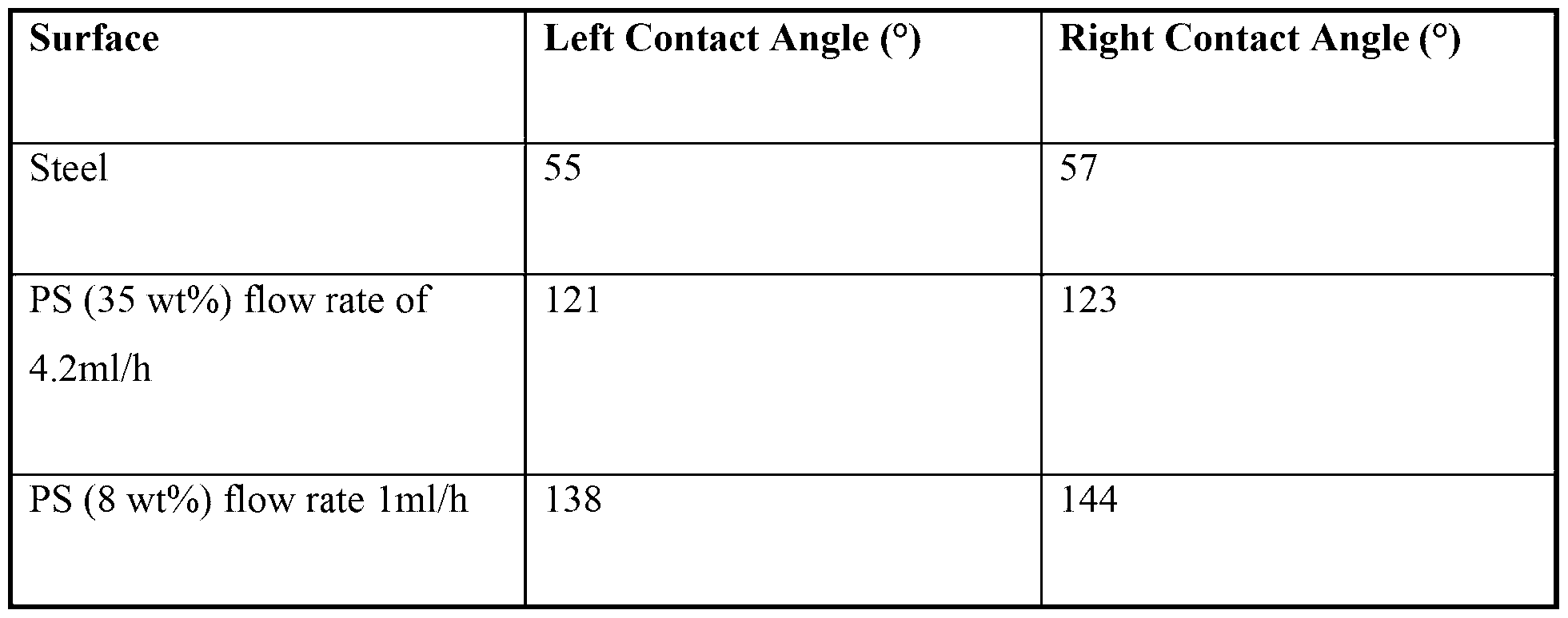
Claims
Priority Applications (3)
| Application Number | Priority Date | Filing Date | Title |
|---|---|---|---|
| AU2015234688A AU2015234688B2 (en) | 2014-03-24 | 2015-03-24 | Film |
| US15/128,484 US10500812B2 (en) | 2014-03-24 | 2015-03-24 | Film |
| EP15768038.0A EP3122558A4 (en) | 2014-03-24 | 2015-03-24 | Film |
Applications Claiming Priority (2)
| Application Number | Priority Date | Filing Date | Title |
|---|---|---|---|
| AU2014901036 | 2014-03-24 | ||
| AU2014901036A AU2014901036A0 (en) | 2014-03-24 | Film |
Publications (1)
| Publication Number | Publication Date |
|---|---|
| WO2015143481A1 true WO2015143481A1 (en) | 2015-10-01 |
Family
ID=54193766
Family Applications (1)
| Application Number | Title | Priority Date | Filing Date |
|---|---|---|---|
| PCT/AU2015/000170 Ceased WO2015143481A1 (en) | 2014-03-24 | 2015-03-24 | Film |
Country Status (4)
| Country | Link |
|---|---|
| US (1) | US10500812B2 (en) |
| EP (1) | EP3122558A4 (en) |
| AU (1) | AU2015234688B2 (en) |
| WO (1) | WO2015143481A1 (en) |
Families Citing this family (15)
| Publication number | Priority date | Publication date | Assignee | Title |
|---|---|---|---|---|
| JP6568545B2 (en) | 2014-06-26 | 2019-08-28 | イー・エム・デイー・ミリポア・コーポレイシヨン | Filter structure with enhanced dirt retention capacity |
| US11058521B2 (en) | 2014-08-18 | 2021-07-13 | University of Central Oklahoma | Method and apparatus for improving osseointegration, functional load, and overall strength of intraosseous implants |
| US10932910B2 (en) | 2014-08-18 | 2021-03-02 | University of Central Oklahoma | Nanofiber coating to improve biological and mechanical performance of joint prosthesis |
| US9809906B2 (en) * | 2014-08-18 | 2017-11-07 | University of Central Oklahoma | Method and apparatus to coat a metal implant with electrospun nanofiber matrix |
| US11013827B2 (en) * | 2016-04-30 | 2021-05-25 | Bvw Holding Ag | Microstructured haptotaxic implant |
| EP3655142B1 (en) | 2017-07-21 | 2026-02-25 | Merck Millipore Ltd | Non-woven fiber membranes |
| KR20210058979A (en) * | 2018-11-01 | 2021-05-24 | 이엠디 밀리포어 코포레이션 | Efficient production of nanofiber structures |
| TWI715908B (en) * | 2019-01-02 | 2021-01-11 | 國立清華大學 | Method of preparing biodegradable film |
| JP6815432B2 (en) * | 2019-03-29 | 2021-01-20 | 大和製罐株式会社 | Liquid-repellent heat seal film and coating agent |
| KR20200127351A (en) * | 2019-05-02 | 2020-11-11 | 전남대학교산학협력단 | Method of forming nanoparticles having superhydrophobicity |
| US20210165134A1 (en) * | 2019-12-02 | 2021-06-03 | Ripclear Llc | Anti-fog lens covering systems |
| JP2023037936A (en) * | 2021-09-06 | 2023-03-16 | 国立大学法人 東京大学 | thin film |
| EP4543968A1 (en) * | 2022-06-23 | 2025-04-30 | Aetherphlox AB | New composite layer and method of producing a composite layer |
| CN115386132B (en) * | 2022-08-12 | 2023-06-20 | 华南理工大学 | Low-dielectric polyimide film using electrospun polymer organic porous film as hole-forming sacrificial template and preparation method thereof |
| CN120285669B (en) * | 2025-05-08 | 2026-04-07 | 西南科技大学 | A method for preparing and applying MOFs-based dual-scale polyimide three-dimensional network nanofiber membranes |
Citations (3)
| Publication number | Priority date | Publication date | Assignee | Title |
|---|---|---|---|---|
| US5395305A (en) * | 1990-08-30 | 1995-03-07 | Terumo Kabushiki Kaisha | Multilayer wound covering materials comprising a supporting layer and a moisture permeation controlling layer and method for their manufacture |
| US20100183950A1 (en) * | 2008-12-19 | 2010-07-22 | University Of Dayton | Metal-free vertically-aligned nitrogen-doped carbon nanotube catalyst for fuel cell cathodes |
| US20110294037A1 (en) * | 2010-05-27 | 2011-12-01 | Gm Global Technology Operations, Inc. | Electrode containing nanostructured thin catalytic layers and method of making |
Family Cites Families (7)
| Publication number | Priority date | Publication date | Assignee | Title |
|---|---|---|---|---|
| US8679580B2 (en) | 2003-07-18 | 2014-03-25 | Ppg Industries Ohio, Inc. | Nanostructured coatings and related methods |
| US7790304B2 (en) * | 2005-09-13 | 2010-09-07 | 3M Innovative Properties Company | Catalyst layers to enhance uniformity of current density in membrane electrode assemblies |
| US20070148531A1 (en) * | 2005-12-22 | 2007-06-28 | Canon Kabushiki Kaisha | Catalyst electrode, production process thereof, and polymer electrolyte fuel cell |
| US8349427B2 (en) * | 2008-07-31 | 2013-01-08 | Illinois Tool Works Inc. | Dye migration-resistant heat transfer label |
| KR20110051249A (en) * | 2008-08-15 | 2011-05-17 | 메사추세츠 인스티튜트 오브 테크놀로지 | Layered assembly of carbon-based nanostructures and their use in energy storage and production devices |
| JP2012033466A (en) * | 2010-07-02 | 2012-02-16 | Fujifilm Corp | Conductive layer transfer material, and touch panel |
| US20130330501A1 (en) * | 2010-07-19 | 2013-12-12 | Joanna Aizenberg | Hierarchical structured surfaces to control wetting characteristics |
-
2015
- 2015-03-24 US US15/128,484 patent/US10500812B2/en not_active Expired - Fee Related
- 2015-03-24 EP EP15768038.0A patent/EP3122558A4/en not_active Withdrawn
- 2015-03-24 AU AU2015234688A patent/AU2015234688B2/en not_active Ceased
- 2015-03-24 WO PCT/AU2015/000170 patent/WO2015143481A1/en not_active Ceased
Patent Citations (3)
| Publication number | Priority date | Publication date | Assignee | Title |
|---|---|---|---|---|
| US5395305A (en) * | 1990-08-30 | 1995-03-07 | Terumo Kabushiki Kaisha | Multilayer wound covering materials comprising a supporting layer and a moisture permeation controlling layer and method for their manufacture |
| US20100183950A1 (en) * | 2008-12-19 | 2010-07-22 | University Of Dayton | Metal-free vertically-aligned nitrogen-doped carbon nanotube catalyst for fuel cell cathodes |
| US20110294037A1 (en) * | 2010-05-27 | 2011-12-01 | Gm Global Technology Operations, Inc. | Electrode containing nanostructured thin catalytic layers and method of making |
Non-Patent Citations (4)
| Title |
|---|
| A. MATAA. FLEISCHMANS. ROY, BIOMED. MICRODEVICES, vol. 7, 2005, pages 281 |
| BORYSIEWICZ M.A.: "Nanocoral ZnO films fabricated on flexible poly(vinyl chloride) using a carrier substrate", THIN SOLID FILMS, vol. 550, 29 October 2013 (2013-10-29), pages 145 - 148, XP055227082, ISSN: 0040-6090 * |
| CASPER ET AL.: "Controlling Surface Morphology of Electrospun Polystyrene Fibers: Effect of Humidity and Molecular Weight in the Electrospinning Process", MACROMOLECULES, 2004, pages 573 - 578, XP055073514, DOI: 10.1021/ma0351975 |
| See also references of EP3122558A4 |
Also Published As
| Publication number | Publication date |
|---|---|
| EP3122558A1 (en) | 2017-02-01 |
| EP3122558A4 (en) | 2017-12-20 |
| US10500812B2 (en) | 2019-12-10 |
| US20170100912A1 (en) | 2017-04-13 |
| AU2015234688B2 (en) | 2018-09-27 |
| AU2015234688A1 (en) | 2016-09-29 |
Similar Documents
| Publication | Publication Date | Title |
|---|---|---|
| AU2015234688B2 (en) | Film | |
| Torun et al. | Water impact resistant and antireflective superhydrophobic surfaces fabricated by spray coating of nanoparticles: interface engineering via end-grafted polymers | |
| Zhang et al. | Flexible and superhydrophobic composites with dual polymer nanofiber and carbon nanofiber network for high-performance chemical vapor sensing and oil/water separation | |
| Liu et al. | Cotton fabrics with single-faced superhydrophobicity | |
| Ogawa et al. | Super-hydrophobic surfaces of layer-by-layer structured film-coated electrospun nanofibrous membranes | |
| Tan et al. | Functional shape memory composite nanofibers with graphene oxide filler | |
| KR102494180B1 (en) | Low refractive index layer, laminated film, method for manufacturing low refractive index layer, method for manufacturing laminated film, optical member and image display device | |
| Ding et al. | Conversion of an electrospun nanofibrous cellulose acetate mat from a super-hydrophilic to super-hydrophobic surface | |
| Zhou et al. | A superhydrophobic poly (lactic acid) electrospun nanofibrous membrane surface-functionalized with TiO 2 nanoparticles and methyltrichlorosilane for oil/water separation and dye adsorption | |
| US8568834B2 (en) | Superhydrophilic coating compositions and their preparation | |
| Gao et al. | Durable superhydrophobic and underwater superoleophobic cotton fabrics growing zinc oxide nanoarrays for application in separation of heavy/light oil and water mixtures as need | |
| US10947355B2 (en) | Functional surfaces and methods of making thereof | |
| EP2681259A2 (en) | Polymers having superhydrophobic surfaces | |
| CN107109125B (en) | Paint and method of making the same | |
| CN111164140B (en) | Void layer, laminate, method for producing void layer, optical member, and optical device | |
| Zheng et al. | Superhydrophobic poly (vinylidene fluoride) film fabricated by alkali treatment enhancing chemical bath deposition | |
| Kumar et al. | Poly (1, 6-heptadiyne)/ABS functionalized microfibers for hydrophobic applications | |
| Zhang et al. | Antireflective superhydrophobic and robust coating based on chitin nanofibers and methylsilanized silica for outdoor applications | |
| CN108137815B (en) | Porous body gel-containing liquid, method for producing same, high-porosity layer, high-porosity porous body, and method for producing laminated film coil | |
| CN107148350B (en) | Laminated film coil and method for producing same | |
| Yi et al. | Polyurethane-coated polyaniline/SiO2 nanoparticle electrospun nanofiber membranes for waterproof and moisture-permeable materials | |
| JP5433512B2 (en) | Method for producing water-insoluble nanofiber | |
| Ras et al. | Superhydrophobic and superoleophobic nanostructured cellulose and cellulose composites | |
| Shah et al. | Synthesis of transparent electrospun composite nanofiber membranes by asymmetric solvent evaporation process | |
| Qian et al. | Protonation and dip-coating synergistically enhancing dimensional stability of multifunctional cellulose-based films |
Legal Events
| Date | Code | Title | Description |
|---|---|---|---|
| 121 | Ep: the epo has been informed by wipo that ep was designated in this application |
Ref document number: 15768038 Country of ref document: EP Kind code of ref document: A1 |
|
| DPE1 | Request for preliminary examination filed after expiration of 19th month from priority date (pct application filed from 20040101) | ||
| REEP | Request for entry into the european phase |
Ref document number: 2015768038 Country of ref document: EP |
|
| WWE | Wipo information: entry into national phase |
Ref document number: 2015768038 Country of ref document: EP |
|
| WWE | Wipo information: entry into national phase |
Ref document number: 15128484 Country of ref document: US |
|
| NENP | Non-entry into the national phase |
Ref country code: DE |
|
| ENP | Entry into the national phase |
Ref document number: 2015234688 Country of ref document: AU Date of ref document: 20150324 Kind code of ref document: A |