WO2015145587A1 - データベースシステム、情報処理装置、方法およびプログラム - Google Patents
データベースシステム、情報処理装置、方法およびプログラム Download PDFInfo
- Publication number
- WO2015145587A1 WO2015145587A1 PCT/JP2014/058382 JP2014058382W WO2015145587A1 WO 2015145587 A1 WO2015145587 A1 WO 2015145587A1 JP 2014058382 W JP2014058382 W JP 2014058382W WO 2015145587 A1 WO2015145587 A1 WO 2015145587A1
- Authority
- WO
- WIPO (PCT)
- Prior art keywords
- node
- data
- identification information
- request
- transaction log
- Prior art date
- Legal status (The legal status is an assumption and is not a legal conclusion. Google has not performed a legal analysis and makes no representation as to the accuracy of the status listed.)
- Ceased
Links
Images


Classifications
-
- G—PHYSICS
- G06—COMPUTING OR CALCULATING; COUNTING
- G06F—ELECTRIC DIGITAL DATA PROCESSING
- G06F16/00—Information retrieval; Database structures therefor; File system structures therefor
- G06F16/20—Information retrieval; Database structures therefor; File system structures therefor of structured data, e.g. relational data
- G06F16/27—Replication, distribution or synchronisation of data between databases or within a distributed database system; Distributed database system architectures therefor
- G06F16/273—Asynchronous replication or reconciliation
-
- G—PHYSICS
- G06—COMPUTING OR CALCULATING; COUNTING
- G06F—ELECTRIC DIGITAL DATA PROCESSING
- G06F16/00—Information retrieval; Database structures therefor; File system structures therefor
- G06F16/20—Information retrieval; Database structures therefor; File system structures therefor of structured data, e.g. relational data
- G06F16/21—Design, administration or maintenance of databases
- G06F16/215—Improving data quality; Data cleansing, e.g. de-duplication, removing invalid entries or correcting typographical errors
-
- G—PHYSICS
- G06—COMPUTING OR CALCULATING; COUNTING
- G06F—ELECTRIC DIGITAL DATA PROCESSING
- G06F16/00—Information retrieval; Database structures therefor; File system structures therefor
- G06F16/20—Information retrieval; Database structures therefor; File system structures therefor of structured data, e.g. relational data
- G06F16/23—Updating
- G06F16/2358—Change logging, detection, and notification
-
- G—PHYSICS
- G06—COMPUTING OR CALCULATING; COUNTING
- G06F—ELECTRIC DIGITAL DATA PROCESSING
- G06F16/00—Information retrieval; Database structures therefor; File system structures therefor
- G06F16/20—Information retrieval; Database structures therefor; File system structures therefor of structured data, e.g. relational data
- G06F16/24—Querying
- G06F16/248—Presentation of query results
Definitions
- the present invention relates to a technique for managing a database.
- Patent Document 1 a database management system that receives a transaction log transmitted from another server node in preparation for its own failure and reflects the received transaction log in a database has been proposed (see Patent Document 1).
- the master creates a plurality of transaction logs in parallel, sends the plurality of transaction logs created in parallel to other masters or slaves, and the other masters or slaves in parallel with the plurality of transaction logs in the database.
- a technique to be applied has been proposed (see Patent Document 2).
- an object of the present invention is to accept queries from user terminals at a plurality of nodes while saving storage and memory in a database system.
- the present invention employs the following means in order to solve the above-described problems. That is, the present invention is a database system having a plurality of nodes, and among the plurality of nodes, the first node uses the transaction log of the database managed by the first node as the transaction log.
- Log holding means for holding the order of such instructions together with identification information that can be grasped, and a second node that is different from the first node among the plurality of nodes, of data managed by the first node Specific identification information indicating a transaction log at a predetermined point in time for the requested data, among the identification information held by the log holding means in response to the transmission request, a request receiving means for receiving a transmission request Specific identification information transmitting means for transmitting to the second node, and at least the token after the predetermined time point.
- Log transmission means for transmitting the transaction log and the identification information to the second node in association with each other, and in response to the transmission request, requested data among the data managed by the database
- Data transmission means for transmitting to the second node after the time point, the second node accepting a search request from a user terminal, and in response to the search request, the second node Request transmission means for transmitting the transmission request for data related to at least the search request in the database to one node; from the first node, the transaction log, identification information of the transaction log, and the specification Receiving means for receiving the identification information and the data; and the received data is stored in the memory of the second node.
- an instruction related to the transaction log that is newer than the transaction log indicated by the specific identification information among the received transaction logs is stored in the memory.
- a search response means to be returned to the user terminal, and data obtained from the first node as a result of the search request and executed by the command based on the transaction is used for a response by the search response means, And a deletion unit that automatically deletes from the second node according to a condition. It is.
- the first node in response to a request from the second node that has received the search request, specific identification information indicating a transaction log at a predetermined time point, a transaction log after the predetermined time point, And data after a predetermined time is transmitted to the second node. Then, the second node expands the received data into a memory and puts it into a state for search or the like (for example, a page including the data is a so-called cache), and issues a command related to a transaction log after a predetermined time point. Executed on the data (cache) expanded in the memory.
- data is acquired in response to a search request, and a command related to a transaction log is executed (reflecting the transaction log) at the time when it is expanded in a memory to be used for search or the like. Queries from user terminals are accepted while saving storage and memory used for replication.
- the deletion unit may delete the data when a predetermined time has elapsed from a time point related to the processing related to the data.
- the second node determines whether or not the data obtained from the first node as a result of the search request and for which the instruction based on the transaction is executed is to be retained in the second node. And a deletion unit that automatically deletes data that has not been determined to be retained by the determination unit in accordance with the predetermined condition.
- the second node may further include recording means for recording the data determined as the retention target by the determination means in a nonvolatile storage device.
- the data transmission means may transmit the data for each predetermined management unit that is divided so that records in which the order of instructions related to the transaction log are dependent on each other are included in the same management unit. .
- the database system includes the predetermined management unit in which data to be commanded is accommodated based on at least the transaction log indicated by the specific identification information among the received transaction logs.
- Map generating means for generating a map showing the relationship between the command contents and the instruction content, wherein the execution means refers to the map and executes the command related to the transaction log for each predetermined management unit. Also good.
- the database system indicates a relationship between the data to be commanded and the content of the command based on at least the transaction log that is newer than the transaction log indicated by the specific identification information among the received transaction logs.
- Map generation means for generating a map may be further provided, and the execution means may execute an instruction related to the transaction log with respect to data to be an instruction target with reference to the map.
- the data transmission means may transmit data in a state of being developed in the memory of the first node and used for data search or processing to the second node.
- the data transmission unit transmits the management information of the database to the second node, and the request transmission unit refers to the management information to the first node in the database.
- the transmission request may be transmitted by designating the data.
- the second node further includes expansion means for directly expanding the data received from the first node into a memory for use in data search or processing, and the execution means includes the received data as the expansion.
- an instruction relating to the transaction log may be executed on the data.
- the specific identification information transmitting unit may transmit, as the specific identification information, identification information indicating the latest transaction log among the identification information held by the log holding unit.
- data may be transmitted and received in units of tables or pages.
- the execution means may execute the command related to the transaction log with respect to the received data according to the order of the commands grasped by the identification information.
- the present invention can be understood as a computer system, an information processing apparatus, a method executed by a computer, or a program executed by a computer.
- the present invention can also be understood as a program recorded on a recording medium readable by a computer, other devices, machines, or the like.
- a computer-readable recording medium refers to a recording medium that accumulates information such as data and programs by electrical, magnetic, optical, mechanical, or chemical action and can be read from a computer or the like.
- FIG. 5 is a flowchart illustrating a flow of management information transmission / reception processing executed by a first node and a second node in the embodiment. In an embodiment, it is a flow chart which shows a flow of database transmission and reception processing performed by the 1st node and the 2nd node. In an embodiment, it is a flow chart which shows a flow of map generation processing performed by the 2nd node. 6 is a flowchart illustrating a flow of update execution processing executed by a second node in the embodiment.
- it is a flowchart (1) which shows the flow of the search request response process performed by the 2nd node.
- It is a figure which shows the outline of a function structure of the 1st node which concerns on embodiment, and a 2nd node.
- 6 is a flowchart illustrating a flow of transaction log transmission / reception start processing executed by the first node and the second node in the embodiment.
- it is a flow chart which shows a flow of on-demand processing performed by the 2nd node.
- the write-once type database system is a type of database system that updates data by adding new data without overwriting old data with new data when updating data.
- the system, the information processing apparatus, the method, and the program according to the present disclosure can be widely used for a technique for using data managed by a certain node in another node in a system having a plurality of nodes.
- the application target of the disclosure is not limited to the example shown in the present embodiment.
- FIG. 1 is a diagram illustrating an outline of a hardware configuration of a system according to the present embodiment.
- the system according to the present embodiment includes a plurality of nodes (information processing devices) 1 for responding to a search request (query) from the user terminal 9.
- the plurality of nodes 1 are communicably connected to each other via a network.
- any one of the nodes 1 for which a database has already been constructed can be used as the first node 1A having the original database in the present embodiment.
- the second node 1B that receives data from the first node 1A is a node in which database software is installed, but the contents of the database are not constructed.
- node 1 when describing a node in general without distinguishing between nodes, it is described as “node 1”, and when distinguishing between nodes, “first node 1A” and “second node 1B” are described. As shown, add a subscript.
- any of the master node and the slave node in the database system may be It can be the node 1A or the second node 1B.
- the first node 1A and the second node 1B include control units 10A and 10B including CPUs (Central Processing Units) 11A and 11B, RAMs (Random Access Memory) 12A and 12B, ROMs (Read Only Memory) 13A and 13B, and the like. And auxiliary storage devices 14A and 14B and communication interfaces 15A and 15B.
- control units 10A and 10B including CPUs (Central Processing Units) 11A and 11B, RAMs (Random Access Memory) 12A and 12B, ROMs (Read Only Memory) 13A and 13B, and the like.
- auxiliary storage devices 14A and 14B and communication interfaces 15A and 15B auxiliary storage devices 14A and 14B and communication interfaces 15A and 15B.
- the specific hardware configuration of the node 1 can be appropriately omitted, replaced, or added according to the embodiment.
- the node 1 is not limited to a single device.
- the node 1 may be realized by a plurality of devices using a so-called cloud or distributed computing technology
- each record in the database is managed in units of pages, and data exchange between the storage (for example, auxiliary storage devices 14A and 14B) and the memory (for example, RAM 12A and 12B) is performed. This is done in units of pages.
- data that has been expanded in a memory or the like and is used for data search or processing is referred to as a cache.
- the data on the storage is not being used for data retrieval or processing. That is, when the contents of the database are targeted for processing such as search and update, each node reads a page including the target record from the storage and uses it as a cache, and performs processing related to the target record.
- each node stores the update of the database by writing a cache page including the record to the storage. Note that the timing at which a page is written to the storage is appropriately determined according to the embodiment.
- One or more records are stored in the page.
- the page may be referred to as a block, and corresponds to a “predetermined management unit” of the present invention.
- data is requested in units of pages and data is transmitted and received in units of pages even in a transmission / reception process between nodes described later.
- performing reading / writing and transmission / reception of data in units of pages is an example of a specific configuration that can be employed when implementing the present disclosure, and the technical scope of the present disclosure includes reading / writing in units of pages. It is not limited to writing and transmission / reception. Data read / write and transmission / reception may be performed in units of tables, for example, or may be performed in other management units.
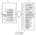
- FIG. 2 is a diagram showing an outline of a functional configuration of the first node 1A and the second node 1B according to the present embodiment.
- the CPU 11A interprets and executes various programs expanded in the RAM 12A, and controls various hardware provided in the node 1A, whereby the log holding unit 21, the request It functions as a computer including the receiving unit 22, the specific identification information transmitting unit 23, the log transmitting unit 24, and the data transmitting unit 25.
- the functions of the first node 1A are executed by the general-purpose CPU 11A. However, some or all of these functions are realized by one or a plurality of dedicated processors. May be.
- the log holding unit 21 is identification information that can grasp a transaction log (hereinafter referred to as “transaction log”) in a database managed by the first node 1A in a time-series order of instructions included in the transaction. Hold with LSN (Log Sequence Number).
- the command includes an update command related to database update and a management command related to transaction management.
- a transaction log is generated every time a transaction occurs in a node, and an LSN is added and held by the log holding unit 21.
- the request reception unit 22 receives a transmission request for data managed by the first node 1A and transmitted by the second node 1B.
- the specific identification information transmission unit 23 transmits the specific identification information (specific LSN) indicating the transaction log at a predetermined time among the LSNs held by the log holding unit 21 to the data transmission request received by the request reception unit 22. In response, the data is transmitted to the second node 1B.
- the specific LSN transmitted here may be determined for each requested page.
- the specific identification information transmission unit 23 transmits an LSN indicating the latest transaction log as the specific LSN.
- the specific LSN to be transmitted is not limited to the LSN indicating the latest transaction log as long as it indicates the transaction log at a predetermined time point for determining the transaction log to be reflected in the second node 1B. .
- the log transmission unit 24 transmits at least a transaction log and an LSN after a predetermined time indicated by the specific LSN to the second node 1B in association with each other. After starting the transmission of the transaction log, the log transmission unit 24 sequentially transmits the newly generated transaction log to the second node 1B.
- the data transmission unit 25 is a page related to the request among the pages managed by the database in response to the data transmission request received by the request reception unit 22, and at least contents up to a predetermined time point related to the specific LSN Is transmitted to the second node 1B.
- the data transmission unit 25 divides data into a predetermined management unit (in this embodiment, divided in such a way that records in which the order of update commands based on the transaction log are mutually dependent are included in the same management unit. , Page).
- the data transmission unit 25 transmits data that is expanded in the memory of the first node 1A and is used for data search or processing, that is, cache, to the second node 1B. To do.
- the first node 1A reads the target page from the storage and sets it as a cache. This is because, in the database system according to the present embodiment, the update of data generated in each node 1 is immediately reflected in the cache, and the cache represents the latest state of the data.
- the data to be transmitted can be a page that reflects the contents up to a predetermined time related to a specific LSN that is an LSN indicating the latest transaction log. .
- the data to be transmitted is not limited to the cache employed in the present embodiment, as long as it reflects at least the contents up to a predetermined time relating to the specific LSN.
- the database system to which the present disclosure is applied can guarantee that the data in the storage reflects at least the contents up to a predetermined time related to the specific LSN, the data read from the storage May be transmitted as is.
- the CPU 11B interprets and executes various programs expanded in the RAM 12B, and controls various hardware provided in the node 1B, whereby the request transmission unit 31.
- Functioning as a computer including a data reception unit 32, an execution unit 33, a map generation unit 34, a search request reception unit 35, a search response unit 36, and a development unit 37.
- a data reception unit 32 an execution unit 33, a map generation unit 34, a search request reception unit 35, a search response unit 36, and a development unit 37.
- the functions of the second node 1B are executed by the general-purpose CPU 11B.
- some or all of these functions are realized by one or a plurality of dedicated processors. May be.
- the request transmission unit 31 transmits a data transmission request to the first node 1A by designating data in the database.
- the designation of data is performed on a page basis.
- the data receiving unit 32 receives the transaction log, the LSN of the transaction log, the specific LSN for each page, and data from the first node 1A. As described above, in the present embodiment, data transmission / reception is performed in units of pages.
- the execution unit 33 is transmitted from the first node 1A in response to the data transmission request, and the data received by the data reception unit 32 is expanded in the memory of the second node 1B for data search or processing. Executes update instructions included in the transaction log that is newer than the transaction log related to the specific LSN among the received transaction logs to the data expanded in the memory when the state becomes available (cache) To do.
- the update command included in the transaction log is executed according to the order grasped by the LSN.
- the map generation unit 34 Based on a transaction log that is at least newer than the transaction log indicated by the specific LSN among the received transaction logs, the map generation unit 34 includes a page containing data that is a target of an update instruction included in the transaction log, and the page A map showing the relationship with the update command is generated.
- the map generation unit 34 since data is managed with pages, the map generation unit 34 generates a map indicating the relationship between the update instruction and the page containing the data to be updated.
- the map generation means may generate a map indicating the relationship between other management units (for example, a table or the like) and the update command. Further, the map generation means may generate a map indicating the relationship between the record to be the update command and the update command without using such a management unit.
- the search request receiving unit 35 receives a search request (query) from the user terminal 9.
- the search response unit 36 returns a response to the search request (query) to the user terminal 9 based on the data obtained from the first node 1A and reflecting the update command based on the transaction log.
- the expansion unit 37 expands the data received from the first node 1A in the memory, and provides the data for search or processing.
- the expansion unit 37 uses the data received from the first node 1A as a cache in response to a query or a request in an update execution process, which will be described later.
- FIG. 3 is a flowchart showing the flow of management information transmission / reception processing executed by the first node 1A and the second node 1B in the present embodiment. The processing shown in this flowchart is started when the second node 1B receives an instruction to start database construction.
- a management information request is transmitted / received.
- the request transmission unit 31 specifies database management information (system catalog or the like) and transmits a data transmission request to the first node 1A (step S101).
- the management information includes information that can specify the position of the table or record in the database. Since the database according to the present embodiment is managed in units of pages, the management information includes information that can specify the relationship between the database table and the page. In the present embodiment, management information is read / written and transmitted / received in units of pages as in other tables. However, the management information may be requested according to other units such as a table unit, similar to the above-described data read / write and transmission / reception.
- the request receiving unit 22 receives the request transmitted by the second node 1B (step S102). Thereafter, the process proceeds to step S103.
- a response to the data transmission request (acknowledgment, hereinafter referred to as “ACK”) is transmitted and received.
- This ACK includes the specific LSN of the management information.
- the LSN is identification information capable of grasping the order of instructions (update instructions) included in the transaction log
- the specific LSN is a predetermined point in time among LSNs held by the log holding unit 21. Is an LSN indicating the transaction log (the latest transaction log in this embodiment). That is, the specific identification information transmission unit 23 transmits an ACK including the specific LSN related to the requested management information among the LSNs held by the log holding unit 21 to the second node 1B (step S103). ).
- the data receiving unit 32 receives an ACK including the specific LSN from the first node 1A (step S104). Thereafter, the process proceeds to step S105.
- step S105 and step S106 transmission / reception of a transaction log is started.
- the log transmission unit 24 transmits a transaction log and an LSN after a predetermined time point to the second node 1B in association with each other (step S105). Thereafter, the transaction log generated in the first node 1A is sequentially and continuously transmitted to the second node 1B.
- the “predetermined time point” is a time point when the transaction log indicated by the specific LSN transmitted in step S103 is generated.
- the data receiving unit 32 starts receiving the transaction log and the LSN related to the transaction log transmitted by the first node 1A (step S106).
- a transaction log newly generated in the first node 1A is transmitted to the second node 1B and received by the second node 1B as soon as it occurs. That is, the second node 1B receives all transaction logs after a predetermined time after the log transmission is started. Thereafter, the process proceeds to step S107.
- the processing order is not limited to the example shown in this flowchart.
- all the transaction logs after the time indicated by the specific LSN among the transaction logs related to the target page may be received by the second node 1B. For this reason, for example, the processing order of the transmission / reception processing in steps S103 and S104 and the transmission / reception processing in steps S105 and S106 may be switched.
- step S107 a map generation process is started for management information.
- the map generation unit 34 sets a page related to management information as a target of map generation processing. That is, after this step, generation of a map in which a combination of an update command executed on the management information and an execution target (target page, target table, target record, etc.) of the update command is started is started.
- the map generation process is executed in parallel with the process shown in this flowchart. Details of the map generation processing will be described with reference to FIG. Thereafter, the process proceeds to step S108.
- step S108 and step S109 database management information is transmitted and received.
- the data transmission unit 25 transmits database management information (system catalog or the like) to the second node 1B (step S108).
- the data transmission unit 25 transmits a cache of data to be transmitted to the second node 1B.
- the first node 1A reads the target data from the storage as a cache, and at least the data reflecting the contents up to a predetermined time related to the specific LSN To the second node 1B.
- the data receiving unit 32 of the second node 1B receives management information from the first node 1A (step S109). Thereafter, the process proceeds to step S110.
- step S108 the transmission of management information (step S108) is described after the start of map generation (step S107), but the management information is transmitted after a predetermined time related to the specific LSN.
- the transmission timing is not limited to the example shown in this flowchart.
- step S110 update execution processing is started.
- the execution unit 33 sets a page related to management information as a target of update execution processing. That is, after this step, an update command not reflected in the management information recorded in the map in the map generation process is executed.
- the update execution process is executed in parallel with the process shown in this flowchart. Details of the update execution process will be described with reference to FIG. Thereafter, the process proceeds to step S111.
- step S111 acceptance of a search request (query) is started.
- the second node 1B starts accepting a query transmitted from the user terminal 9 by starting the search request handling process.
- the search request receiving unit 35 receives a query from the user terminal 9, and when the query is received, a page necessary for responding to the query is acquired by referring to the management information.
- the search request handling process is executed in parallel with the process shown in this flowchart. Details of the search request handling process will be described with reference to FIGS. Thereafter, the processing shown in this flowchart ends.
- management information is duplicated using the map generation process, the update execution process, and the search request handling process, as with other tables in the database.
- Other methods may be employed.
- duplicating the management information for example, a conventional method of creating a checkpoint and duplicating a snapshot of the checkpoint can be employed.
- FIG. 4 is a flowchart showing the flow of database transmission / reception processing executed by the first node 1A and the second node 1B in the present embodiment.
- the processing shown in this flowchart allows the second node 1B to grasp the database page configuration managed by the first node 1A by receiving the database management information from the first node 1A. It starts when it becomes.
- a data transmission request is transmitted and received.
- the request transmission unit 31 refers to the management information cache, and transmits a data transmission request to the first node 1A by designating a page in the database (step S201). For example, a page number may be used for designating a page.
- the data transmission request may be a page specifying a page or a specific record in the database. In this embodiment, data is requested in units of pages, but it may be requested in accordance with other units such as a table as described above.
- the request receiving unit 22 receives a data transmission request managed by the first node 1A from the second node 1B (step S202). Thereafter, the process proceeds to step S203.
- step S203 and step S204 an ACK for the data transmission request is transmitted / received.
- This ACK includes the page number and the specific LSN of the page. That is, the specific identification information transmission unit 23 transmits an ACK including the specific LSN related to the requested page among the LSNs held by the log holding unit 21 to the second node 1B (step S203). .
- the data receiving unit 32 receives an ACK including the specific LSN from the first node 1A (step S204). Thereafter, the process proceeds to step S205.
- step S205 the map generation process is started for the page related to the request.
- the map generation unit 34 sets the page requested in step S201 as a target of map generation processing. That is, after this step, generation of a map in which a combination of an update instruction executed on the requested page and a target of execution of the update instruction (target page, target table, target record, etc.) is started is started.
- the content of the map generation process started here is substantially the same as that started for the management information in step S107 (see FIG. 5), and is processed in parallel with the process shown in this flowchart. . Thereafter, the process proceeds to step S206.
- map generation start timing is different for each management information and page (see step S107 and step S205), but the map generation start timing is the same for the entire database. May be.
- step S206 and step S207 the requested page is transmitted and received.
- the data transmission unit 25 transmits the requested page among the pages managed by the database to the second node 1B (step S206). At this time, the data transmission unit 25 transmits a cache of data to be transmitted to the second node 1B.
- the first node 1A reads the target page from the storage as a cache, and at least as a page reflecting the contents up to a predetermined time related to the specific LSN To the second node 1B.
- the data receiving unit 32 of the second node 1B receives data from the first node 1A (step S207).
- the data transmission / reception unit may be any unit according to the request, and may be any of a page unit, a table unit, and a record unit. Thereafter, the process proceeds to step S208.
- step S206 the transmission of data (step S206) is described after the start of map generation (step S205).
- step S205 the transmission of data
- the transmission timing is not limited to the example shown in this flowchart.
- step S208 update execution processing is started.
- the execution unit 33 sets the data received in step S207 as a target for the update execution process. That is, after this step, an unexecuted update command recorded in the map by the map generation process is executed. Thereafter, the processing shown in this flowchart ends.
- the database transmission / reception process shown in FIG. The process is repeatedly executed while sequentially changing the requested page until acquisition of the page is completed. That is, the request transmission unit 31 transmits a data transmission request for all pages or tables grasped by referring to the management information by repeating the processing from step S201 to step S208. However, if it is not necessary for the second node 1B to acquire all the data in the database of the first node 1A, the request transmission unit 31 can store the data only for some necessary pages and tables. A transmission request may be made.
- step S201 an example in which the processing from step S201 to step S208 is repeated when a plurality of pages is acquired has been described. However, when a plurality of pages are acquired, a plurality of pages are collectively requested in step S201. It is good as well.
- the data received from the first node 1A is temporarily stored in the storage.
- the expansion unit 37 expands the data received from the first node 1A directly into the memory without passing through the storage (the auxiliary storage device 14B in this embodiment), and the data You may use for search or processing.
- the update command related to the received data is immediately reflected according to the map generation process described later.
- the database of the second node 1B is managed by map generation processing, update execution processing, and search request response processing.
- the second node 1B launches a plurality of instances for executing these processes as appropriate and executes them in parallel, thereby generating a map, reflecting a mapped update instruction, and processing a search request (query). Can be processed in parallel.
- FIG. 5 is a flowchart showing the flow of map generation processing executed by the second node 1B in this embodiment. The process shown in this flowchart is repeatedly executed on the data (see Step S107 and Step S205) that is the target of the map generation process.
- step S301 instructions included in the transaction log are referred to in chronological order with reference to the LSN.
- the second node 1B refers to the instructions included in the unreflected transaction log in order from the oldest point in time (the one with the smallest LSN).
- the transaction log referred to here is one received and received by the second node 1B after transmission / reception is started in the processing of step S105 and step S106. Thereafter, the process proceeds to step S302.
- step S302 and step S303 it is determined whether or not the instruction is an update instruction, and an instruction other than the update instruction is executed.
- the second node 1B determines whether or not the instruction referred to in step S301 is an update instruction (step S302). If the referenced instruction is an instruction other than the update instruction (for example, a management instruction such as commit), the instruction is executed as it is (step S303). On the other hand, if the referenced instruction is an update instruction, the process proceeds to step S304.
- step S304 it is determined whether or not the page indicated by the referenced instruction is the target of map generation processing.
- the second node 1B determines whether the target data is set as a target for map generation processing in step S107, step S205, or the like.
- the process shown in the flowchart ends.
- the process proceeds to step S305.
- step S305 it is determined whether or not the target data (page) cache exists. If the referenced instruction is an update instruction, the second node 1B determines that the update instruction (for example, a DELETE instruction) whose target exists in the database when the instruction is referenced is the target of the update instruction. It is determined whether or not the cache exists. On the other hand, for an update instruction (for example, an INSERT instruction) whose target does not exist in the database when the instruction is referenced, whether or not there is a cache of data in the area where the target of the update instruction is inserted It is determined whether or not the cache subject to the update instruction exists. When records are managed in units of pages, the second node 1B determines whether there is a cache of a page including the update command target. If there is a cache for the target page, the process proceeds to step S306. On the other hand, if there is no cache for the target page, the process proceeds to step S307.
- the update instruction for example, a DELETE instruction
- step S306 an update command related to the transaction log is executed.
- the execution unit 33 executes an update command related to the transaction log on the received data that is expanded in the memory by the expansion unit 37 and becomes a cache. Thereafter, the process proceeds to step S308.
- step S307 a map is generated.
- the map generation unit 34 is the target of the update command included in the transaction log. Information indicating the relationship between the page in which the data is stored and the update command is recorded in the map, thereby waiting for execution of the update command.
- the map generation unit 34 maps the update instruction as a target of mapping (map generation) and records the content of the standby update instruction in association with the record. Generate.
- all update instructions may be targets for map generation.
- At least one of the content of the update command that has been waited and the LSN is recorded in the map in association with the page (specifically, the page number) that includes the record that is the target of the update command. . Thereafter, the process proceeds to step S308.
- step S308 it is determined whether or not to end the map generation process. If the map generation process is not completed, the process returns to step S301, the next command is referred to in the time series order (LSN order) in the transaction log, and is the target of the process shown in steps S304 to S307.
- the map generation process is repeatedly executed while the second node 1B is operated. That is, in the present embodiment, the second node 1B inspects the received transaction logs in order from the oldest one, and the page that is the target of the update command included in the transaction log is on-memory (cache). In this case, an update command corresponding to the transaction log is executed for the cache.
- the map generation process is terminated because the second node 1B is stopped, the process illustrated in this flowchart is terminated.
- the map generated by the map generation process is referred to in the update execution process or the search request handling process when the target page becomes a cache, and the update is made to wait in the map in the update execution process or the search request handling process
- the instruction is executed. That is, according to the system according to the present embodiment, the reflection of the transaction log with respect to the data received from the first node is delayed until the time when the target data is actually used (in other words, the time when the data becomes a cache). I can do it.
- the transaction log recording the contents of the update command is held in the RAM 12B or the auxiliary storage device 14B of the node 1B.
- the update execution process or the search request handling process the transaction log held in the RAM 12 or the storage device 14 is accessed based on the LSN recorded in the map, and the contents of the update command to be executed are specified.
- the content of the update command or the LSN is recorded in the map according to the referred order.
- the execution order of the waited update instructions can be recognized.
- the update command is updated by the LSN of the waited update command. Can recognize the execution order.
- FIG. 6 is a flowchart showing the flow of update execution processing executed by the second node 1B in this embodiment. The processing shown in this flowchart is repeatedly executed while there is an update command waiting in the map.
- step S401 it is determined whether there is a waiting update command.
- the second node 1B refers to the map and determines whether or not there is a waiting update command. If the waiting update command is not recorded in the map, the processing shown in this flowchart is terminated. On the other hand, when the waiting update command is recorded in the map, the second node 1B selects the management unit including the data to be the target of the update command as the processing target, and performs the processing in step S402. Proceed to
- step S402 it is determined whether there is an update target.
- the second node 1B determines whether or not the processing target selected in step S401 exists in the second node 1B. In other words, the page to be processed has already been received from the first node 1A. It is determined whether or not it is done. If there is no page to be updated, the process returns to step S401. That is, the second node 1B refers to the map and waits for an update command waiting for a page existing in the second node 1B. If there is a page to be updated, the process proceeds to step S404.
- step S403 an update command related to the update target page is extracted from the map.
- the second node 1B extracts all update instructions for the update target page determined to exist in step S402 from the map. In this way, all the update instructions on the map relating to the update target page are executed, and the page on which the update instruction is executed can be directly used as a cache for data search or processing. Thereafter, the process proceeds to step S404.
- step S404 the expansion unit 37 reads the target to be processed from the auxiliary storage device 14B into the RAM 12B, thereby forming a cache. Thereafter, the process proceeds to step S405.
- step S405 and step S406 the update command waiting in the map and the extracted update command are executed, and the executed update command is deleted from the map.
- the execution unit 33 refers to the map and executes an update command associated with the processing target selected by the execution unit 33 (step S405). That is, the execution unit 33 executes the update command found in step S401 and the update command extracted in step S403 for each page that is a predetermined management unit in the order recorded in the map. For example, when the update command is a delete command, the execution unit 33 gives a delete pointer to the target record. Then, the second node 1B deletes the record relating to the executed update command from the map after executing the update command waiting for the processing target selected by itself (step S406). Thereafter, the process proceeds to step S407.
- step S407 it is determined whether or not to end the update execution process. If the update execution process is not terminated, the process returns to step S401. That is, in the update execution process, when a plurality of update commands are waiting on the page selected as the processing target, the standby update commands are executed in the order recorded in the map (LSN order). Thereby, with respect to the page, the consistency of the database can be maintained while replication is being executed between the node 1 and the replication source computer. On the other hand, when the update execution process is terminated, for example, because the second node 1B is stopped, the process illustrated in this flowchart is terminated.
- the second node 1B may launch a plurality of instances for executing the update execution process. By generating, deleting, starting, or stopping such instances, the second node 1B The number may be increased or decreased.
- the second node 1B may increase or decrease the number of instances to be activated in accordance with the number of management units (in the present embodiment, the number of pages) of update instructions that are recorded in a waiting state that are recorded in the map. Good.
- the processing capability of the update execution process can be changed according to the request, and it is possible to avoid the useless instance, so that resources can be efficiently used.
- a predetermined number of instances for executing the update execution process may be activated in advance. In this case, it is not necessary to start an instance again when a request for processing occurs, so that it is possible to quickly respond to the generated request.
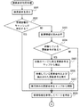
- FIGS. 7 and 8 are flowcharts showing the flow of the search request handling process executed by the second node 1B in the present embodiment. The process shown in this flowchart is started when the second node 1B receives a query from the user terminal 9 or the like.
- step S501 a query is accepted.
- the search request receiving unit 35 receives a query from the user terminal 9. Thereafter, the process proceeds to step S502.
- step S502 it is determined whether or not a management information cache exists.
- the search response unit 36 determines whether or not a management information cache exists in the memory. In this embodiment, since records are managed in units of pages, the search response unit 36 determines whether there is a page cache including management information as a search target.
- the search response unit 36 does not read from the storage area, refers to the management information that already has a cache, and the process proceeds to step S508. On the other hand, if there is no management information cache, the process advances to step S503.
- step S503 management information is read from the storage.
- management information transmission / reception processing is performed at the time of starting construction of the database (see FIG. 3)
- the second node 1B Management information is stored in the storage.
- the expansion unit 37 reads the management information from the storage (auxiliary storage device 14B) to the RAM 12B. Thereafter, the process proceeds to step S504.
- step S504 it is determined whether there is a waiting update command.
- the second node 1B refers to the map and determines whether or not there is an update command waiting for the management information page read into the RAM 12B. If the update instruction waiting for the page read into the RAM 12B is not recorded in the map, the process proceeds to step S508. On the other hand, if an update command waiting for the page read into the RAM 12B is recorded in the map, the process proceeds to step S505.
- step S505 an update command related to the update target page is extracted from the map.
- the second node 1B extracts all update instructions for the update target page (in this case, the page including the management information) determined to exist in step S503 from the map. In this way, all the update instructions on the map relating to the update target page are executed, and the page on which the update instruction is executed can be directly used as a cache for data search or processing. Thereafter, the process proceeds to step S506.
- step S506 and step S507 the update instruction waiting in the map and the extracted update instruction are executed, and the executed update instruction is deleted from the map.
- the execution unit 33 refers to the map and executes an update command associated with the management information read to the RAM 12B (step S506). That is, in the present embodiment, the second node 1B expands the management information (step S207) received by the data receiving unit 32 in the memory (step S503) according to the query (step S501), and based on the map. The update command is executed on the management information.
- the execution unit 33 executes the standby update commands in the order recorded in the map.
- the second node 1B executes all the update instructions waiting for the management information read to the RAM 12B, and then deletes the record related to the executed update instruction from the map (step S507). Thereafter, the process proceeds to step S508.
- step S508 the management information is referred to identify the page.
- the search response unit 36 refers to the management information in order to specify the storage area specified as the search range by the received query.
- a page including data necessary for processing a query is specified by referring to management information. Thereafter, the process proceeds to step S511.
- step S511 it is determined whether or not there is a cache of the search target data (page).
- the search response unit 36 accesses the storage area specified in the search range by the query in order to extract a record that matches the content of the received query. Then, the search response unit 36 determines whether or not a record cache relating to the query exists in the memory. In the present embodiment, since records are managed in units of pages, the search response unit 36 determines whether or not there is a cache of a page including a record to be searched.
- an update command that is put on standby is executed for the page (the processing shown in steps S515 to S518 in FIG. 6 and FIG. 8 to be described later). reference).
- an update instruction for a page in which a cache exists is immediately executed (see the map generation process described with reference to FIG. 5). For this reason, in this embodiment, when the cache of the page included in the search range already exists (when the determination result in step S511 is “YES”), the execution of the update instruction for the page is not awaited. .
- the search response unit 36 does not read from the storage area, sets the page that already has the cache as the target of the search process, and the process proceeds to step S519. On the other hand, if there is no cache for the target page, the process proceeds to step S512.
- step S512 it is determined whether the search target page exists in the storage (database) of the second node 1B. As described above, in this embodiment, since the page transmission request is sequentially performed (see step S201), when the second node 1B does not have a page related to the query at the time of receiving the query. There is. If it is determined that the page does not exist in the storage, the process proceeds to step S514 in order to acquire the corresponding page from the first node 1A. On the other hand, if it is determined that the page exists in the storage, the process proceeds to step S513.
- step S514 the database transmission / reception process shown in FIG. 4 is executed. If it is determined in step S512 that the page does not exist in the storage, the request transmission unit 31 transmits at least data related to the query in the database to the first node 1A and transmits a data transmission request.
- the pages shown in the management information are obtained in order by repeating the database transmission / reception process shown in FIG. 4, but the page that is the search target in response to the search request in step S501 is as follows. Ignoring this order, data transmission is requested with priority. That is, according to the present embodiment, a page that is a search target in response to a search request can be preferentially a target of a request (data transmission request). Thereafter, the process returns to step S511.
- step S501 the response to the query accepted in step S501 is that the target page is the first node 1A. Wait until it is acquired.
- step S513 the search target page is read from the storage.
- the expansion unit 37 reads the page from the storage (auxiliary storage device 14B) to the RAM 12B when there is no cache of the search target data (page), but exists in the storage of the second node 1B, and performs the search processing target. And Thereafter, the process proceeds to step S515.
- the expansion unit 37 when the expansion unit 37 reads out pages included in the search range from the auxiliary storage device 14B to the RAM 12B, for example, the expansion unit 37 may read out the target pages one by one, or may read out a plurality of pages at once. Good. In this case, every time one or more pages are read, the execution unit 33 executes the processing from step S515 described later on the read one or more pages.
- step S515 it is determined whether there is a waiting update command.
- the second node 1B refers to the map and determines whether there is an update instruction waiting for the page read to the RAM 12B. If the update instruction waiting for the page read into the RAM 12B is not recorded in the map, the process proceeds to step S519. On the other hand, when the update command waiting for the page read into the RAM 12B is recorded in the map, the process proceeds to step S516.
- step S516 an update command related to the update target page is extracted from the map.
- the second node 1B extracts all update instructions for the update target page determined to exist in step S515 from the map. In this way, all the update instructions on the map relating to the update target page are executed, and the page on which the update instruction is executed can be directly used as a cache for data search or processing. Thereafter, the process proceeds to step S517.
- step S517 and step S518, the update command waiting in the map and the extracted update command are executed, and the executed update command is deleted from the map.
- the execution unit 33 refers to the map and executes an update command related to the page read to the RAM 12B (step S517). That is, in the present embodiment, the second node 1B expands the data (step S207) received by the data receiving unit 32 in the memory (step S513) according to the query (step S501), and based on the map. An update instruction is executed on the data.
- the execution unit 33 executes the standby update commands in the order recorded in the map (LSN order). Then, the second node 1B deletes the record relating to the executed update command from the map after executing all the update commands waiting for the page read to the RAM 12B (step S518). Thereafter, the process proceeds to step S519.
- the search request handling process similarly to the update execution process, when a plurality of update commands are waiting on the page selected as the processing target, the standby is performed in the order recorded in the map (LSN order). Update instructions are executed. Thereby, the consistency of the database can be maintained between the first node 1A and the second node 1B for the page.
- step S519 the search response unit 36 performs a search process corresponding to the received query on the page obtained from the first node 1A and reflecting the update command. Thereafter, the process proceeds to step S520.
- step S520 a response to the search request (query) is transmitted.
- the search response unit 36 transmits the result of the search process to the user terminal 9 as a response to the query. Thereafter, the processing shown in this flowchart ends.
- the second node 1B may launch a plurality of instances for executing the search request handling process, and execute the search request handling process by generating, deleting, starting or stopping such instances. You may increase or decrease the number of instances. For example, the second node 1B may increase or decrease the number of instances to be activated according to the number of queries received from the user terminal 9. In this case, the processing capability of the search request handling process can be made variable according to the request, and it is possible to avoid the useless instances, so that resources can be efficiently used.
- the search request handling process may be executed in a plurality of instances.
- the process from step S515 to step S518 may be executed in an instance different from other processes.
- the processing is performed from step S515 to step S518 for page updating. Takes over to the second instance to execute. Then, when the process of step S518 in the second instance is completed, the process returns to the first instance, and the search process of step S519 is executed.
- data is transferred to the first node 1A for each database portion (predetermined management unit such as a page) without batch copying the entire database and without creating a checkpoint.
- the second node 1B can reflect the transaction log in parallel for each part of the database without worrying about the dependency relationship between the update commands based on the transaction log.
- the execution of the update command based on the transaction log can be delayed, and when the received data is expanded in the memory, the update command based on the transaction log based on the map, It can be executed in parallel for each predetermined management unit.
- the received data can be used for a query in the second node 1B without waiting for the completion of replication of the entire database.
- data transmission from the first node 1A to the second node 1B is performed in response to a data transmission request, so that data acquisition is performed sequentially.
- the timing of acquisition can be adjusted.
- the data to be searched can be preferentially acquired or prioritized. It is possible to reflect the transaction log. That is, according to the system according to the present embodiment, it is possible to accept a search request from the user terminal in a state where the second node 1B has not received all the data.
- the system according to the second embodiment adds a configuration to the system according to the first embodiment so that the second node can respond to the query without holding the entire database in the second node. Is.
- the entire database is held in the second node.
- the data in the database is held. It is not permanently held in the second node except for those that are determined to be targets.
- the same reference numerals are given to the same components as those of the system according to the first embodiment described above, and the description thereof is omitted.
- FIG. 9 is a diagram schematically showing the functional configuration of the first node 1A and the second node 1B ′ according to the present embodiment. Since the functional configuration of the first node 1A according to the present embodiment is substantially the same as that of the first embodiment, description thereof is omitted.
- the CPU 11B interprets and executes various programs expanded in the RAM 12B, and controls various hardware provided in the node 1B ′, whereby the request transmission unit 31. , Functioning as a computer including a data reception unit 32, an execution unit 33, a map generation unit 34, a search request reception unit 35, a search response unit 36, a development unit 37, a determination unit 38, a recording unit 39, and a deletion unit 40.
- the functions of the second node 1B ′ are executed by the general-purpose CPU 11B, but some or all of these functions are realized by one or more dedicated processors. May be.
- the request transmission unit 31, the data reception unit 32, the execution unit 33, the map generation unit 34, the search request reception unit 35, the search response unit 36, and the expansion unit 37 are substantially the same as those in the first embodiment, a description will be given. Omitted.
- the determination unit 38 determines whether or not the data obtained from the first node 1A in response to the search request and for which the instruction based on the transaction is executed is to be held in the second node 1B ′.
- the recording unit 39 records the data determined to be retained by the determination unit 38 in the auxiliary storage device 14B that is a nonvolatile storage device.
- the deletion unit 40 uses the data obtained from the first node 1A in response to the search request and for which the command based on the transaction is executed for the response by the search response unit 36, and then automatically performs the second operation according to a predetermined condition. Delete from the node.
- the database transmission / reception processing (see FIG. 4), map generation processing (see FIG. 5), and update execution processing (see FIG. 6) described in the first embodiment are also executed in the second embodiment. . Details of these processes are the same as those described in the first embodiment, and thus description thereof is omitted.
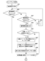
- FIG. 10 is a flowchart showing the flow of transaction log transmission / reception start processing executed by the first node 1A and the second node 1B ′ in the present embodiment.
- the process shown in this flowchart is a process that is executed in place of the management information transmission / reception process (see FIG. 3) described in the first embodiment, and is triggered when an instruction to start construction of a database is received. Started as.
- step S801 and step S802 a transaction log request is transmitted / received.
- the request transmission unit 31 transmits a transaction log transmission request to the first node 1A (step S801).
- the request receiving unit 22 receives the request transmitted by the second node 1B ′ (step S802). Thereafter, the process proceeds to step S803.
- step S803 and step S804 transmission / reception of a transaction log is started. Thereafter, the log transmission unit 24 sequentially transmits the transaction log and the LSN newly generated in the first node 1A to the second node 1B ′ in association with each other as soon as they are generated (step S803).
- the data receiving unit 32 of the second node 1B ′ starts to receive the transaction log and the LSN related to the transaction log transmitted by the first node 1A (step S804). That is, the second node 1B 'receives all the transaction logs after a predetermined time after the log transmission is started. Thereafter, the process proceeds to step S805.
- step S805 acceptance of a search request (query) is started.
- the second node 1B ′ starts accepting a query transmitted from the user terminal 9 by starting an on-demand process described later. Thereafter, the search request accepting unit 35 accepts a query from the user terminal 9, and when the query is accepted, a page (including management information) necessary for responding to the query is acquired. Thereafter, the processing shown in this flowchart ends.
- the management information transmission / reception process is not performed at the start of database construction.
- the database transmission / reception processing shown in FIG. 4 has been described as “started when it becomes possible to grasp the page configuration of the database managed by the first node 1A” in the first embodiment.
- the second embodiment is executed at a timing that is called in an on-demand process described later (see steps S605 and S514 described later).
- FIG. 11 is a flowchart showing the flow of on-demand processing executed by the second node 1B ′ in this embodiment.
- the processing shown in this flowchart is started when the second node 1B 'receives a query from the user terminal 9 or the like. That is, in the present embodiment, on-demand processing is executed instead of the search request response processing (see FIGS. 7 and 8) described in the first embodiment.
- the management information transmission / reception process is not performed at the start of the database construction. For this reason, there is a possibility that the second node 1B 'does not have management information when the search request is accepted. If the second node 1B 'does not have management information, the page related to the query cannot be specified in the data transmission request. For this reason, in the on-demand processing according to the present embodiment, when a search request is accepted, it is first confirmed whether or not the second node 1B 'has management information. If the second node 1B 'does not have management information, the database transmission / reception process is executed after obtaining the management information from the first node 1A. Details of the on-demand processing according to the present embodiment will be described below with reference to FIG.
- step S601 a query is accepted.
- the search request receiving unit 35 receives a query from the user terminal 9. Thereafter, the process proceeds to step S602.
- step S602 it is determined whether or not a management information cache exists.
- the search response unit 36 determines whether or not a management information cache exists in the memory. In this embodiment, since records are managed in units of pages, the search response unit 36 determines whether there is a page cache including management information as a search target.
- step S6 when a page including management information is read to the RAM 12B, an update command that has been put on standby is executed for the page (the process shown in FIG. 6 and steps S606 to S609 described later). See).
- an update instruction for a page in which a cache exists is immediately executed (see the map generation process described with reference to FIG. 5).
- the cache of the page including the management information already exists when the determination result in step S602 is “YES”), the execution of the update command for the page is not awaited. Therefore, when there is a cache of the page including the management information, the search response unit 36 does not read from the storage area, refers to the management information that already has a cache, and the process proceeds to step S610. On the other hand, if there is no management information cache, the process advances to step S603.
- step S603 it is determined whether or not a page including management information exists in the storage (database) of the second node 1B '.
- the management information transmission / reception process is not performed at the time of starting construction of the database. Therefore, at the time of receiving the query, the second node 1B ′ There is a case where management information for specifying is not provided. If it is determined that the management information does not exist in the storage, the process proceeds to step S605 in order to acquire the management information from the first node 1A. On the other hand, if it is determined that the page exists in the storage, the process proceeds to step S604.
- step S605 the database transmission / reception process shown in FIG. 4 is executed. If it is determined in step S603 that the management information does not exist in the storage, the request transmission unit 31 specifies the data related to the management information to the first node 1A in response to the query and sends a data transmission request. Send. As described above, in this embodiment, management information is transmitted and received in units of pages as in the other tables. Therefore, management information can be acquired by the database transmission / reception processing shown in FIG. Thereafter, the process returns to step S602. Then, the processes shown in steps S602 to S605 are repeated until management information is acquired from the first node 1A.
- step S604 management information is read from the storage.
- the expansion unit 37 reads the management information from the storage (auxiliary storage device 14B) to the RAM 12B when the management information cache does not exist but exists in the storage of the second node 1B '. Thereafter, the process proceeds to step S606.
- step S606 it is determined whether there is a waiting update command.
- the second node 1B ' refers to the map and determines whether there is an update command waiting for the management information page read into the RAM 12B. If the update instruction waiting for the page read into the RAM 12B is not recorded in the map, the process proceeds to step S610. On the other hand, if an update command waiting for the page read into the RAM 12B is recorded in the map, the process proceeds to step S607.
- step S607 an update command related to the update target page is extracted from the map.
- the second node 1B ′ extracts all update instructions for the update target page (in this case, the page including the management information) determined to exist in step S603 from the map. In this way, all the update instructions on the map relating to the update target page are executed, and the page on which the update instruction is executed can be directly used as a cache for data search or processing. Thereafter, the process proceeds to step S608.
- step S608 and step S609 the update command waiting in the map and the extracted update command are executed, and the executed update command is deleted from the map.
- the execution unit 33 refers to the map and executes an update command related to the management information read to the RAM 12B (step S608). That is, in the present embodiment, the second node 1B ′ expands the management information (step S207) received by the data receiving unit 32 in the memory (step S604) according to the query (step S601), and displays it in the map. Based on this, an update command is executed on the management information.
- the execution unit 33 executes the standby update commands in the order recorded in the map. Then, the second node 1B ′ executes all the update instructions waiting for the management information read to the RAM 12B, and then deletes the record relating to the executed update instruction from the map (step S609). Thereafter, the process proceeds to step S610.
- step S610 the management information is referred to identify the page.
- the search response unit 36 refers to the management information in order to specify the storage area specified as the search range by the received query.
- a page including data necessary for processing a query is specified by referring to management information.
- a request (data transmission request) is first received by receiving a search request and becoming a search target. Thereafter, the processing shown in steps S519 and S520 is executed, and when the response to the query is completed, the processing shown in this flowchart ends.
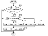
- FIG. 12 is a flowchart showing the flow of deletion processing executed by the second node 1B ′ in the present embodiment.
- the processing shown in this flowchart is periodically executed for each data unit (in this embodiment, page unit) that is expanded in the memory and becomes a cache in the second node 1B '.
- step S701 it is determined whether or not the data satisfies the deletion condition.
- the deletion unit 40 determines whether or not a predetermined deletion condition is satisfied for the cache related to the determination target page among the caches on the second node 1B '.
- the deletion condition used here is, for example, that a predetermined time has elapsed since a time point related to data processing (a time point obtained from the first node 1A, a time point last referenced for a query response, an update, or the like). And so on.
- the deletion condition is not limited to the illustration in the present embodiment.
- step S702 it is determined whether or not the data is a retention target.
- the determination unit 38 determines whether or not the determination target page of the data held by the second node 1B ′ is to be held by the second node 1B ′.
- the condition for determination may be determined based on, for example, the frequency with which the data is referred to in the query.
- the storage and memory of the second node 1B ′ can be stored without sacrificing the response speed to the query by setting the frequently referenced data to be held and not the less frequently data to be held. Can be saved.
- a table or page designated in advance by an administrator or the like can be set as a holding target.
- the determination condition as to whether or not to hold is not limited to the example in the present embodiment.
- the determination condition can be appropriately adopted according to the embodiment. If the determination target page does not satisfy the condition for being held, the process advances to step S704. On the other hand, if the page to be determined satisfies the conditions for becoming a holding target, the process proceeds to step S703.
- step S703 data is recorded in the storage.
- the recording unit 39 records data (determined in units of pages in the present embodiment) determined to be retained by the determination unit 38 in a storage (in the present embodiment, the auxiliary storage device 14B). Thereafter, the process proceeds to step S705.
- step S704 data that satisfies the deletion condition is deleted from the storage.
- the deletion unit 40 determines that data determined by the determination unit 38 as not being held (determined in units of pages in this embodiment) is recorded in the storage of the second node 1B ′. Are deleted from the storage (in this embodiment, the auxiliary storage device 14B). In this way, data that has been received and temporarily recorded in the storage before it becomes a cache can also be deleted from the storage. Thereafter, the process proceeds to step S705.
- step S705 the data cache that satisfies the deletion condition is deleted.
- the deletion unit 40 deletes the cache of the page that satisfies the deletion condition from the memory of the second node 1B ′. Thereafter, the processing shown in this flowchart ends.
- step S702 it is determined whether or not the cached data is to be deleted. However, when data that is stored in the storage but is not cached is periodically determined whether or not it is a storage target, the condition for the storage target (see step S702) is no longer satisfied. May be deleted from the storage. In this way, even data that is held only in the storage can be deleted from the storage over time, and the storage capacity can be saved.
Landscapes
- Engineering & Computer Science (AREA)
- Theoretical Computer Science (AREA)
- Databases & Information Systems (AREA)
- Data Mining & Analysis (AREA)
- Physics & Mathematics (AREA)
- General Engineering & Computer Science (AREA)
- General Physics & Mathematics (AREA)
- Computational Linguistics (AREA)
- Quality & Reliability (AREA)
- Computing Systems (AREA)
- Information Retrieval, Db Structures And Fs Structures Therefor (AREA)
Abstract
Description
はじめに、第一の実施形態について説明する。
図1は、本実施形態に係るシステムのハードウェア構成の概略を示す図である。本実施形態に係るシステムは、ユーザー端末9からの検索要求(クエリ)に応答するための複数のノード(情報処理装置)1を備える。複数のノード1は、ネットワークを介して互いに通信可能に接続される。複数のノード1のうち、データベースが既に構築されているノード1の何れかを、本実施形態におけるオリジナルのデータベースを有する第一のノード1Aとすることが出来る。また、本実施形態において第一のノード1Aからデータを受信する第二のノード1Bは、データベース用のソフトウェアがインストールされているが、データベースのコンテンツが未構築のノードである。本実施形態では、このようなシステムにおいて、第一のノード1Aが管理するデータベースのコンテンツ(データ)を、第二のノード1Bにおける検索の用に供するための技術を説明する。本実施形態では、ノードを区別することなくノード一般について述べる場合には「ノード1」と記載し、ノードを区別して述べる場合には「第一のノード1A」、「第二のノード1B」のように添字を付して記載する。
次に、本実施形態に係る処理の詳細を説明する。なお、本実施形態において説明される処理の具体的な内容および順序等は、実施する上での一例である。具体的な処理内容および順序等は、実施の形態に応じて適宜選択されてよい。
本実施形態に係るシステムによれば、データベース全体を一括コピーすること無く、また、チェックポイントを作成すること無く、データベースの部分(ページ等の所定の管理単位)毎にデータを第一のノード1Aから第二のノード1Bに送信出来る。また、第二のノード1Bは、トランザクションログに基づく更新命令同士の依存関係を気にすること無く、データベースの部分毎に並列にトランザクションログを反映することが出来る。また、マップを生成することで、トランザクションログに基づく更新命令の実行を遅延させることが出来、受信されたデータがメモリに展開された場合に、マップに基づいて、トランザクションログに基づく更新命令を、所定の管理単位毎に並列に実行することが出来る。
次に、第二の実施形態について説明する。第二の実施形態に係るシステムは、第二のノードにデータベース全体を保持することなく、第二のノードがクエリに応答可能とするために、第一の実施形態に係るシステムに構成を追加したものである。第一の実施形態では、全てのページについてのデータベース送受信処理が完了した場合、第二のノードにデータベース全体が保持されることとなるが、第二の実施形態では、データベース中のデータは、保持対象と判定されたものを除いて、第二のノードに恒久的には保持されない。第二の実施形態に係るシステムのうち、上述した第一の実施形態のシステムと共通する構成には、同一の符号を付し、説明を省略する。
第二の実施形態に係るシステムのハードウェア構成は、第一の実施形態に係るシステムのハードウェア構成と概略同様であるため、説明を省略する(図1を参照)。但し、第二の実施形態では、第二のノードの機能構成が第一の実施形態とは異なるため、第二のノードに符号「1B’」を付して説明する。
次に、本実施形態に係る処理の詳細を説明する。なお、本実施形態において説明される処理の具体的な内容および順序等は、実施する上での一例である。具体的な処理内容および順序等は、実施の形態に応じて適宜選択されてよい。
第二の実施形態に係るシステムによっても、第一の実施形態に係るシステムと同様の効果を得ることが出来る。また、第二の実施形態では、更に判定部38、記録部39および削除部40を備えることで、第二のノード1B’のストレージやメモリを節約しながら、ユーザー端末9に対して、あたかも第二のノード1B’がデータベース全体に係るデータを有しているかのようにサービスを提供することが出来る。
Claims (17)
- 複数のノードを有するデータベースシステムであって、
前記複数のノードのうち、第一のノードは、
該第一のノードによって管理されているデータベースのトランザクションログを、該トランザクションログに係る命令の順序を把握可能な識別情報とともに保持するログ保持手段と、
前記複数のノードのうち、前記第一のノードと異なる第二のノードから、該第一のノードによって管理されているデータの送信要求を受信する要求受信手段と、
前記送信要求に応じて、前記ログ保持手段によって保持されている前記識別情報のうち、要求されたデータに係る、所定の時点におけるトランザクションログを示す特定識別情報を、前記第二のノードに送信する特定識別情報送信手段と、
少なくとも前記所定の時点より後の前記トランザクションログおよび前記識別情報を、互いに関連づけて前記第二のノードに送信するログ送信手段と、
前記送信要求に応じて、前記データベースによって管理されているデータのうち要求されたデータを、前記所定の時点以降に、前記第二のノードに送信するデータ送信手段と、
を備え、
前記第二のノードは、
ユーザー端末からの検索要求を受け付ける検索要求受付手段と、
前記検索要求に応じて、前記第一のノードに対して、前記データベース中の少なくとも前記検索要求に係るデータの前記送信要求を送信する要求送信手段と、
前記第一のノードから、前記トランザクションログ、該トランザクションログの識別情報、前記特定識別情報および前記データを受信する受信手段と、
受信された前記データが該第二のノードのメモリに展開されてデータの検索または処理に供される状態となった場合に、受信された前記トランザクションログのうち、少なくとも前記特定識別情報が示すトランザクションログよりも新しい前記トランザクションログに係る命令を、メモリに展開された前記データに対して実行する実行手段と、
前記検索要求の結果前記第一のノードから得られ、前記トランザクションに基づく命令が実行されたデータに基づいて、前記検索要求への応答を前記ユーザー端末に対して返す検索応答手段と、
前記検索要求の結果前記第一のノードから得られ、前記トランザクションに基づく命令が実行されたデータを、前記検索応答手段による応答に用いた後、所定の条件に従って自動的に該第二のノードから削除する削除手段と、
を備える、
データベースシステム。 - 前記削除手段は、前記データに関する処理に関する時点から所定時間経過した場合に、前記データを削除する、
請求項1に記載のデータベースシステム。 - 前記第二のノードは、前記検索要求の結果前記第一のノードから得られ、前記トランザクションに基づく命令が実行されたデータを、該第二のノードにおける保持対象とするか否かを判定する判定手段を更に備え、
前記削除手段は、前記判定手段によって前記保持対象と判定されなかったデータを、前記所定の条件に従って自動的に削除する、
請求項1または2に記載のデータベースシステム。 - 前記第二のノードは、前記判定手段によって前記保持対象と判定されたデータを、不揮発性の記憶装置に記録する記録手段を更に備える、
請求項3に記載のデータベースシステム。 - 前記データ送信手段は、前記データを、前記トランザクションログに係る命令の順序が互いに依存関係にあるレコードが同一の管理単位に入るように区切られた所定の管理単位毎に送信する、
請求項1から4の何れか一項に記載のデータベースシステム。 - 受信された前記トランザクションログのうち、少なくとも前記特定識別情報が示すトランザクションログよりも新しい前記トランザクションログに基づいて、命令の対象となるデータが収容された前記所定の管理単位と命令の内容との関係を示すマップを生成するマップ生成手段を更に備え、
前記実行手段は、前記マップを参照して、前記トランザクションログに係る命令を、前記所定の管理単位毎に実行する、
請求項5に記載のデータベースシステム。 - 受信された前記トランザクションログのうち、少なくとも前記特定識別情報が示すトランザクションログよりも新しい前記トランザクションログに基づいて、命令の対象となるデータと命令の内容との関係を示すマップを生成するマップ生成手段を更に備え、
前記実行手段は、前記マップを参照して、前記トランザクションログに係る命令を、命令の対象となるデータに対して実行する、
請求項1に記載のデータベースシステム。 - 前記データ送信手段は、前記第一のノードのメモリに展開されてデータの検索または処理に供されている状態のデータを、前記第二のノードに送信する、
請求項1から7の何れか一項に記載のデータベースシステム。 - 前記データ送信手段は、前記データベースの管理情報を、前記第二のノードに送信し、
前記要求送信手段は、前記管理情報を参照して、前記第一のノードに対して、前記データベース中のデータを指定して送信要求を送信する、
請求項1から8の何れか一項に記載のデータベースシステム。 - 前記第二のノードは、
前記第一のノードから受信したデータを直接メモリに展開して、データの検索または処理に供する展開手段を更に備え、
前記実行手段は、受信したデータが前記展開手段によってメモリに展開されたことを受けて、前記トランザクションログに係る命令を前記データに対して実行する、
請求項1から9の何れか一項に記載のデータベースシステム。 - 前記特定識別情報送信手段は、前記特定識別情報として、ログ保持手段によって保持されている前記識別情報のうち、最新のトランザクションログを示す識別情報を送信する、
請求項1から10の何れか一項に記載のデータベースシステム。 - 前記データは、テーブル単位またはページ単位で送受信される、
請求項1から11の何れか一項に記載のデータベースシステム。 - 前記実行手段は、前記トランザクションログに係る命令を、前記識別情報によって把握される命令の順序に応じて、受信された前記データに対して実行する、
請求項1から12の何れか一項に記載のデータベースシステム。 - データベースを管理する管理手段と、
前記データベースのトランザクションログを、該トランザクションログに係る命令の順序を把握可能な識別情報とともに保持するログ保持手段と、
他の情報処理装置から、前記データベースによって管理されているデータの送信要求を受信する要求受信手段と、
前記送信要求に応じて、前記ログ保持手段によって保持されている前記識別情報のうち、要求されたデータに係る、所定の時点におけるトランザクションログを示す特定識別情報を、前記他の情報処理装置に送信する特定識別情報送信手段と、
少なくとも前記所定の時点より後の前記トランザクションログおよび前記識別情報を、互いに関連づけて前記他の情報処理装置に送信するログ送信手段と、
前記送信要求に応じて、前記データベースによって管理されているデータのうち要求されたデータを、前記所定の時点以降に、前記他の情報処理装置に送信するデータ送信手段と、
を備える情報処理装置。 - ユーザー端末からの検索要求を受け付ける検索要求受付手段と、
前記検索要求に応じて、データベースを管理する他の情報処理装置に対して、前記データベース中の少なくとも前記検索要求に係るデータの前記送信要求を送信する要求送信手段と、
前記他の情報処理装置から、該データベースのトランザクションログ、該トランザクションログに係る命令の順序を把握可能な識別情報、前記識別情報のうち所定の時点におけるトランザクションログを示す特定識別情報、および前記データベースによって管理されているデータを受信する受信手段と、
受信された前記データがメモリに展開されてデータの検索または処理に供される状態となった場合に、受信された前記トランザクションログのうち、少なくとも前記特定識別情報が示すトランザクションログよりも新しい前記トランザクションログに係る命令を、メモリに展開された前記データに対して実行する実行手段と、
前記検索要求の結果前記他の情報処理装置から得られ、前記トランザクションに基づく命令が実行されたデータに基づいて、前記検索要求への応答を前記ユーザー端末に対して返す検索応答手段と、
前記検索要求の結果前記他の情報処理装置から得られ、前記トランザクションに基づく命令が実行されたデータを、前記検索応答手段による応答に用いた後、所定の条件に従って自動的に該情報処理装置から削除する削除手段と、
を備える情報処理装置。 - 複数のノードを有するデータベースシステムにおいて、
前記複数のノードのうち、第一のノードが、
該第一のノードによって管理されているデータベースのトランザクションログを、該トランザクションログに係る命令の順序を把握可能な識別情報とともに保持するログ保持ステップと、
前記複数のノードのうち、前記第一のノードと異なる第二のノードから、該第一のノードによって管理されているデータの送信要求を受信する要求受信ステップと、
前記送信要求に応じて、前記ログ保持ステップで保持されている前記識別情報のうち、要求されたデータに係る、所定の時点におけるトランザクションログを示す特定識別情報を、前記第二のノードに送信する特定識別情報送信ステップと、
少なくとも前記所定の時点より後の前記トランザクションログおよび前記識別情報を、互いに関連づけて前記第二のノードに送信するログ送信ステップと、
前記送信要求に応じて、前記データベースによって管理されているデータのうち要求されたデータを、前記所定の時点以降に、前記第二のノードに送信するデータ送信ステップと、
を実行し、
前記第二のノードが、
ユーザー端末からの検索要求を受け付ける検索要求受付ステップと、
前記検索要求に応じて、前記第一のノードに対して、前記データベース中の少なくとも前記検索要求に係るデータの前記送信要求を送信する要求送信ステップと、
前記第一のノードから、前記トランザクションログ、該トランザクションログの識別情報、前記特定識別情報および前記データを受信する受信ステップと、
受信された前記データが該第二のノードのメモリに展開されてデータの検索または処理に供される状態となった場合に、受信された前記トランザクションログのうち、少なくとも前記特定識別情報が示すトランザクションログよりも新しい前記トランザクションログに係る命令を、メモリに展開された前記データに対して実行する実行ステップと、
前記検索要求の結果前記第一のノードから得られ、前記トランザクションに基づく命令が実行されたデータに基づいて、前記検索要求への応答を前記ユーザー端末に対して返す検索応答ステップと、
前記検索要求の結果前記第一のノードから得られ、前記トランザクションに基づく命令が実行されたデータを、前記検索応答ステップにおける応答に用いた後、所定の条件に従って自動的に該第二のノードから削除する削除ステップと、
を実行する、
方法。 - 複数のノードを有するデータベースシステムにおいて、
前記複数のノードのうち、第一のノードを、
該第一のノードによって管理されているデータベースのトランザクションログを、該トランザクションログに係る命令の順序を把握可能な識別情報とともに保持するログ保持手段と、
前記複数のノードのうち、前記第一のノードと異なる第二のノードから、該第一のノードによって管理されているデータの送信要求を受信する要求受信手段と、
前記送信要求に応じて、前記ログ保持手段によって保持されている前記識別情報のうち、要求されたデータに係る、所定の時点におけるトランザクションログを示す特定識別情報を、前記第二のノードに送信する特定識別情報送信手段と、
少なくとも前記所定の時点より後の前記トランザクションログおよび前記識別情報を、互いに関連づけて前記第二のノードに送信するログ送信手段と、
前記送信要求に応じて、前記データベースによって管理されているデータのうち要求されたデータを、前記所定の時点以降に、前記第二のノードに送信するデータ送信手段と、
として機能させ、
前記第二のノードを、
ユーザー端末からの検索要求を受け付ける検索要求受付手段と、
前記検索要求に応じて、前記第一のノードに対して、前記データベース中の少なくとも前記検索要求に係るデータの前記送信要求を送信する要求送信手段と、
前記第一のノードから、前記トランザクションログ、該トランザクションログの識別情報、前記特定識別情報および前記データを受信する受信手段と、
受信された前記データが該第二のノードのメモリに展開されてデータの検索または処理に供される状態となった場合に、受信された前記トランザクションログのうち、少なくとも前記特定識別情報が示すトランザクションログよりも新しい前記トランザクションログに係る命令を、メモリに展開された前記データに対して実行する実行手段と、
前記検索要求の結果前記第一のノードから得られ、前記トランザクションに基づく命令が実行されたデータに基づいて、前記検索要求への応答を前記ユーザー端末に対して返す検索応答手段と、
前記検索要求の結果前記第一のノードから得られ、前記トランザクションに基づく命令が実行されたデータを、前記検索応答手段による応答に用いた後、所定の条件に従って自動的に該第二のノードから削除する削除手段と、
として機能させる、
プログラム。
Priority Applications (4)
| Application Number | Priority Date | Filing Date | Title |
|---|---|---|---|
| EP14886733.6A EP3125123A4 (en) | 2014-03-25 | 2014-03-25 | Database system, information processing device, method, and program |
| JP2016509682A JP6461101B2 (ja) | 2014-03-25 | 2014-03-25 | データベースシステム、情報処理装置、方法およびプログラム |
| PCT/JP2014/058382 WO2015145587A1 (ja) | 2014-03-25 | 2014-03-25 | データベースシステム、情報処理装置、方法およびプログラム |
| US15/274,446 US10579604B2 (en) | 2014-03-25 | 2016-09-23 | Database system, information processing device, method and medium |
Applications Claiming Priority (1)
| Application Number | Priority Date | Filing Date | Title |
|---|---|---|---|
| PCT/JP2014/058382 WO2015145587A1 (ja) | 2014-03-25 | 2014-03-25 | データベースシステム、情報処理装置、方法およびプログラム |
Related Child Applications (1)
| Application Number | Title | Priority Date | Filing Date |
|---|---|---|---|
| US15/274,446 Continuation US10579604B2 (en) | 2014-03-25 | 2016-09-23 | Database system, information processing device, method and medium |
Publications (1)
| Publication Number | Publication Date |
|---|---|
| WO2015145587A1 true WO2015145587A1 (ja) | 2015-10-01 |
Family
ID=54194185
Family Applications (1)
| Application Number | Title | Priority Date | Filing Date |
|---|---|---|---|
| PCT/JP2014/058382 Ceased WO2015145587A1 (ja) | 2014-03-25 | 2014-03-25 | データベースシステム、情報処理装置、方法およびプログラム |
Country Status (4)
| Country | Link |
|---|---|
| US (1) | US10579604B2 (ja) |
| EP (1) | EP3125123A4 (ja) |
| JP (1) | JP6461101B2 (ja) |
| WO (1) | WO2015145587A1 (ja) |
Cited By (1)
| Publication number | Priority date | Publication date | Assignee | Title |
|---|---|---|---|---|
| JP2020504377A (ja) * | 2016-12-23 | 2020-02-06 | イングラム マイクロ インコーポレーテッド | データベースバウンドアプリケーション用にユーザインターフェースバックエンドクラスタをスケーリングするための技術 |
Families Citing this family (3)
| Publication number | Priority date | Publication date | Assignee | Title |
|---|---|---|---|---|
| US10552418B2 (en) * | 2016-12-29 | 2020-02-04 | Ancestry.Com Operations Inc. | Optimization of first set of ordered items and delayed non-duplicated work queue |
| US10678773B2 (en) * | 2017-08-25 | 2020-06-09 | Salesforce.Com, Inc. | Parallel processing of disjoint change streams into a single stream |
| US20200097215A1 (en) * | 2018-09-25 | 2020-03-26 | Western Digital Technologies, Inc. | Adaptive solid state device management based on data expiration time |
Citations (3)
| Publication number | Priority date | Publication date | Assignee | Title |
|---|---|---|---|---|
| JP2009015476A (ja) * | 2007-07-03 | 2009-01-22 | Hitachi Ltd | Cdpリモート構成におけるジャーナル管理方法 |
| WO2010106991A1 (ja) * | 2009-03-19 | 2010-09-23 | 株式会社ココリンク | データの複製管理方法及びシステム |
| JP2013015915A (ja) * | 2011-06-30 | 2013-01-24 | Fujitsu Ltd | 送信制御方法、装置及びプログラム |
Family Cites Families (12)
| Publication number | Priority date | Publication date | Assignee | Title |
|---|---|---|---|---|
| US5353410A (en) | 1992-03-18 | 1994-10-04 | International Business Machines Corporation | Method and system for deferred read in lazy-write disk cache systems |
| US7257699B2 (en) | 2004-07-08 | 2007-08-14 | Sun Microsystems, Inc. | Selective execution of deferred instructions in a processor that supports speculative execution |
| JP4929782B2 (ja) | 2006-03-27 | 2012-05-09 | 富士通株式会社 | ミラーサイト運用プログラム、方法及びミラーサイトサーバコンピュータ |
| JP4833734B2 (ja) | 2006-05-19 | 2011-12-07 | 株式会社日立製作所 | データベースシステム、ストレージ装置、初期コピー方法及びログ適用方法 |
| KR100926880B1 (ko) | 2007-05-21 | 2009-11-16 | 엔에이치엔(주) | Dbms에서의 데이터 복제 방법 및 시스템 |
| KR101265388B1 (ko) | 2009-07-02 | 2013-05-20 | 엔에이치엔비즈니스플랫폼 주식회사 | 고가용성 데이터베이스 관리 시스템 및 이를 이용한 데이터베이스 관리 방법 |
| JP5039891B2 (ja) | 2009-10-19 | 2012-10-03 | インターナショナル・ビジネス・マシーンズ・コーポレーション | データベースの複製を生成する装置及び方法 |
| US20110178984A1 (en) | 2010-01-18 | 2011-07-21 | Microsoft Corporation | Replication protocol for database systems |
| US8671074B2 (en) * | 2010-04-12 | 2014-03-11 | Microsoft Corporation | Logical replication in clustered database system with adaptive cloning |
| CN101860797B (zh) * | 2010-05-21 | 2014-08-13 | 中兴通讯股份有限公司 | 数据信息的传输方法、装置及移动多媒体广播业务系统 |
| US10430298B2 (en) | 2010-10-28 | 2019-10-01 | Microsoft Technology Licensing, Llc | Versatile in-memory database recovery using logical log records |
| JP5724363B2 (ja) | 2010-12-20 | 2015-05-27 | 日本電気株式会社 | 情報処理システム |
-
2014
- 2014-03-25 JP JP2016509682A patent/JP6461101B2/ja active Active
- 2014-03-25 EP EP14886733.6A patent/EP3125123A4/en not_active Withdrawn
- 2014-03-25 WO PCT/JP2014/058382 patent/WO2015145587A1/ja not_active Ceased
-
2016
- 2016-09-23 US US15/274,446 patent/US10579604B2/en active Active
Patent Citations (3)
| Publication number | Priority date | Publication date | Assignee | Title |
|---|---|---|---|---|
| JP2009015476A (ja) * | 2007-07-03 | 2009-01-22 | Hitachi Ltd | Cdpリモート構成におけるジャーナル管理方法 |
| WO2010106991A1 (ja) * | 2009-03-19 | 2010-09-23 | 株式会社ココリンク | データの複製管理方法及びシステム |
| JP2013015915A (ja) * | 2011-06-30 | 2013-01-24 | Fujitsu Ltd | 送信制御方法、装置及びプログラム |
Non-Patent Citations (1)
| Title |
|---|
| See also references of EP3125123A4 * |
Cited By (1)
| Publication number | Priority date | Publication date | Assignee | Title |
|---|---|---|---|---|
| JP2020504377A (ja) * | 2016-12-23 | 2020-02-06 | イングラム マイクロ インコーポレーテッド | データベースバウンドアプリケーション用にユーザインターフェースバックエンドクラスタをスケーリングするための技術 |
Also Published As
| Publication number | Publication date |
|---|---|
| JPWO2015145587A1 (ja) | 2017-04-13 |
| US10579604B2 (en) | 2020-03-03 |
| EP3125123A4 (en) | 2017-11-22 |
| EP3125123A1 (en) | 2017-02-01 |
| JP6461101B2 (ja) | 2019-01-30 |
| US20170011075A1 (en) | 2017-01-12 |
Similar Documents
| Publication | Publication Date | Title |
|---|---|---|
| CN110502507B (zh) | 一种分布式数据库的管理系统、方法、设备和存储介质 | |
| US10747752B2 (en) | Space management for transactional consistency of in-memory objects on a standby database | |
| US12235809B1 (en) | Efficient data backup in a distributed storage system | |
| EP2653986B1 (en) | Client-side caching of a database transaction token. | |
| US9690796B2 (en) | Non-transitory computer-readable media storing file management program, file management apparatus, and file management method | |
| JP2007286860A (ja) | データ転送方法及び情報処理装置 | |
| JP4741371B2 (ja) | システム、サーバ装置及びスナップショットの形式変換方法 | |
| JP6279770B2 (ja) | ファイルサーバ装置 | |
| JP6461101B2 (ja) | データベースシステム、情報処理装置、方法およびプログラム | |
| KR20140047448A (ko) | 트랜잭션 재시작 가능한 클라이언트 장치와 데이터베이스 서버 및 방법 | |
| JP6586174B2 (ja) | データベースシステム、トランザクション管理ノード、方法およびプログラム | |
| JP5721056B2 (ja) | トランザクション処理装置、トランザクション処理方法およびトランザクション処理プログラム | |
| JP6257748B2 (ja) | データベースシステム、情報処理装置、方法およびプログラム | |
| CN117255101B (zh) | 分布式存储系统的数据处理方法、装置、设备及介质 | |
| WO2009147847A1 (ja) | データベース並行編集方式 | |
| US11269735B2 (en) | Methods and systems for performing data backups | |
| WO2016206070A1 (zh) | 一种文件更新方法及存储设备 | |
| US10073874B1 (en) | Updating inverted indices | |
| CN121116971A (zh) | 基于云搜索服务的数据查询方法、介质、设备及产品 | |
| JP4855537B2 (ja) | データベース並行編集方式 | |
| JP4923140B2 (ja) | データベース並行編集方式 | |
| CN121009061A (zh) | 基于云搜索服务的数据查询方法、介质、设备及程序产品 | |
| CN120011326A (zh) | 文件存储方法、读取方法、装置、设备及介质 | |
| JPWO2016117322A1 (ja) | 処理要求装置、処理装置、データベースシステム、データベース更新方法およびプログラム | |
| CN120123421A (zh) | 数据库集群、数据处理方法、数据处理系统及相关设备 |
Legal Events
| Date | Code | Title | Description |
|---|---|---|---|
| 121 | Ep: the epo has been informed by wipo that ep was designated in this application |
Ref document number: 14886733 Country of ref document: EP Kind code of ref document: A1 |
|
| ENP | Entry into the national phase |
Ref document number: 2016509682 Country of ref document: JP Kind code of ref document: A |
|
| NENP | Non-entry into the national phase |
Ref country code: DE |
|
| REEP | Request for entry into the european phase |
Ref document number: 2014886733 Country of ref document: EP |
|
| WWE | Wipo information: entry into national phase |
Ref document number: 2014886733 Country of ref document: EP |