WO2015146030A1 - 携帯端末充電装置と、それを搭載した自動車 - Google Patents
携帯端末充電装置と、それを搭載した自動車 Download PDFInfo
- Publication number
- WO2015146030A1 WO2015146030A1 PCT/JP2015/001332 JP2015001332W WO2015146030A1 WO 2015146030 A1 WO2015146030 A1 WO 2015146030A1 JP 2015001332 W JP2015001332 W JP 2015001332W WO 2015146030 A1 WO2015146030 A1 WO 2015146030A1
- Authority
- WO
- WIPO (PCT)
- Prior art keywords
- coil
- charging
- detection
- foreign object
- charging coil
- Prior art date
- Legal status (The legal status is an assumption and is not a legal conclusion. Google has not performed a legal analysis and makes no representation as to the accuracy of the status listed.)
- Ceased
Links
Images


Classifications
-
- H—ELECTRICITY
- H02—GENERATION; CONVERSION OR DISTRIBUTION OF ELECTRIC POWER
- H02J—ELECTRIC POWER NETWORKS; CIRCUIT ARRANGEMENTS OR SYSTEMS FOR SUPPLYING OR DISTRIBUTING ELECTRIC POWER; SYSTEMS FOR STORING ELECTRIC ENERGY
- H02J7/00—Circuit arrangements for charging or discharging batteries or for supplying loads from batteries
- H02J7/70—Circuit arrangements for charging or discharging batteries or for supplying loads from batteries characterised by the mechanical construction
-
- H—ELECTRICITY
- H02—GENERATION; CONVERSION OR DISTRIBUTION OF ELECTRIC POWER
- H02J—ELECTRIC POWER NETWORKS; CIRCUIT ARRANGEMENTS OR SYSTEMS FOR SUPPLYING OR DISTRIBUTING ELECTRIC POWER; SYSTEMS FOR STORING ELECTRIC ENERGY
- H02J50/00—Circuit arrangements or systems for wireless supply or distribution of electric power
- H02J50/005—Mechanical details of housing or structure aiming to accommodate the power transfer means, e.g. mechanical integration of coils, antennas or transducers into emitting or receiving devices
-
- H—ELECTRICITY
- H02—GENERATION; CONVERSION OR DISTRIBUTION OF ELECTRIC POWER
- H02J—ELECTRIC POWER NETWORKS; CIRCUIT ARRANGEMENTS OR SYSTEMS FOR SUPPLYING OR DISTRIBUTING ELECTRIC POWER; SYSTEMS FOR STORING ELECTRIC ENERGY
- H02J50/00—Circuit arrangements or systems for wireless supply or distribution of electric power
- H02J50/10—Circuit arrangements or systems for wireless supply or distribution of electric power using inductive coupling
- H02J50/12—Circuit arrangements or systems for wireless supply or distribution of electric power using inductive coupling of the resonant type
-
- H—ELECTRICITY
- H02—GENERATION; CONVERSION OR DISTRIBUTION OF ELECTRIC POWER
- H02J—ELECTRIC POWER NETWORKS; CIRCUIT ARRANGEMENTS OR SYSTEMS FOR SUPPLYING OR DISTRIBUTING ELECTRIC POWER; SYSTEMS FOR STORING ELECTRIC ENERGY
- H02J50/00—Circuit arrangements or systems for wireless supply or distribution of electric power
- H02J50/60—Circuit arrangements or systems for wireless supply or distribution of electric power responsive to the presence of foreign objects, e.g. detection of living beings
-
- H—ELECTRICITY
- H02—GENERATION; CONVERSION OR DISTRIBUTION OF ELECTRIC POWER
- H02J—ELECTRIC POWER NETWORKS; CIRCUIT ARRANGEMENTS OR SYSTEMS FOR SUPPLYING OR DISTRIBUTING ELECTRIC POWER; SYSTEMS FOR STORING ELECTRIC ENERGY
- H02J50/00—Circuit arrangements or systems for wireless supply or distribution of electric power
- H02J50/90—Circuit arrangements or systems for wireless supply or distribution of electric power involving detection or optimisation of position, e.g. alignment
Definitions
- the present invention relates to a mobile terminal charging device for charging a mobile terminal such as a mobile phone, and an automobile equipped with the same.
- Mobile terminals such as mobile phones have extremely high functions, and the power consumption increases accordingly.
- such a portable terminal charging device has a support plate whose front side is a portable terminal installation portion, and a charging coil disposed on the back side of the support plate so as to face the support plate.
- the mobile terminal When the mobile terminal is placed on the mobile terminal installation unit, the mobile terminal can be charged with the magnetic flux from the charging coil (for example, Patent Document 1 and Patent Document 2 exist as similar ones). ).
- the present invention provides an easy-to-use portable terminal charging device.
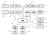
- the portable terminal charging device of the present invention includes a support plate, a charging coil, a driving unit, a control unit, and a memory.
- the surface side of the support plate is a portable terminal installation part.
- the charging coil is movably disposed on the back side of the support plate in a state of facing the support plate.
- the drive unit can move the charging coil on the back side of the support plate.
- the control unit is connected to the charging coil and the driving unit.
- the memory is connected to this control unit.
- the support plate is provided with a plurality of foreign object detection coils and a plurality of position detection coils, and the charging coil is disposed on the inner side of the first detection coil having a large diameter and the first coil. A second detection coil having a smaller diameter than the detection coil is provided.
- the memory stores the reference resonance frequency or reference resonance voltage of each foreign object detection coil at the location where the charging coil is present.
- the control unit detects a foreign object by driving a part of the plurality of foreign object detection coils and then detecting the location of the charging coil by driving the plurality of position detection coils. Perform operations alternately.
- the control unit detects that the resonance frequency detected by the foreign object detection coil corresponding to the location where the charging coil is present is higher than the reference resonance frequency stored in the memory, or the presence of the charging coil.
- the safe operation is executed.
- the control unit When the position detection coil detects the location where the charging coil is present, the control unit energizes the charging coil. After energizing the charging coil, the control unit detects the first voltage (V1) detected by the first detecting coil. When the ratio (V2 / V1) of the second voltage (V2) detected by the second detection coil with respect to ()) becomes smaller than the set value, the safe operation is executed.
- the mobile terminal charging device of the present invention is convenient.
- the control unit drives the plurality of position detection coils after driving a part of the plurality of foreign object detection coils to detect the foreign object, and then charging the coil.
- the operation of detecting the location of the is alternately executed. Therefore, when the mobile terminal is placed on the mobile terminal installation unit, the energization of the charging coil can be started in a shorter time. From this point of view, usability is improved.
- foreign matter detection can be performed by the large-diameter first detection coil and the small-diameter second detection coil provided in the charging coil.
- a part of the plurality of foreign matter detection coils can be driven to easily detect the foreign matter. Accordingly, the time required to detect the foreign matter before the start of energization can be shortened, thereby shortening the time required to start charging the charging coil. From this point of view, usability is improved.
- the mobile terminal installation part is not so large, so the distance from the foreign matter detection coil being driven to the foreign matter is small. Foreign objects can often be detected if they are not far away. Even with such simple foreign object detection, it is highly possible to detect a foreign object.
- foreign matter detection can be performed by the large-diameter first detection coil and the small-diameter second detection coil provided in the above-described charging coil after energization. It can be done reliably. Therefore, safety is high.
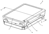
- the perspective view which shows the state which installed the portable terminal charging device which concerns on embodiment of this invention in the vehicle interior of a motor vehicle.
- the perspective view of the portable terminal charging device which concerns on embodiment of this invention The perspective view of the portable terminal charging device shown in FIG.
- the perspective view which shows the state which removed a part of portable terminal charging device shown in FIG. The top view of the portable terminal charging device of the state shown in FIG. Sectional drawing in broken line SS 'of the portable terminal charging device shown in FIG.
- the top view which shows the structure of the support plate of the portable terminal charging device shown in FIG. The perspective view which shows the detection coil of the portable terminal charging device shown in FIG.
- the top view which shows the detection coil of the portable inspection terminal charging device shown in FIG. The figure which shows operation
- movement of the portable terminal charging device shown in FIG. The figure which shows operation
- movement of the portable terminal charging device shown in FIG. Operation flowchart of the portable terminal charging device shown in FIG.
- the figure which shows the relationship between the location where a charging coil exists, and the resonant frequency of a foreign material detection coil The figure which shows the relationship between the location where a charging coil exists, and the resonant voltage of a foreign material detection coil The figure which shows the resonant frequency of a foreign material detection coil in case a metal foreign material exists. The figure which shows the resonant voltage of a foreign material detection coil in case a metal foreign material exists.
- movement of the portable terminal charging device shown in FIG. The figure which shows operation
- the foreign object detection means is constituted by a plurality of metal detection antenna coils and an oscillation circuit connected to each metal detection antenna coil, and foreign object detection is performed by detecting the oscillation frequency of each metal detection antenna coil. Is going. Therefore, it is not preferable from the viewpoint of versatility.
- the conventional example utilizes the fact that the oscillation state of the oscillation circuit changes when a metal foreign object is present, and in such a configuration, the setting of the oscillation circuit becomes an extremely delicate setting state. Therefore, it is useful for charging a portable terminal whose characteristics are known in advance.
- the oscillation state changes in the portable terminal itself, and as a result, charging cannot be performed, which is not preferable from the viewpoint of versatility.
- the foreign matter detection means using a plurality of metal detection antenna coils detects foreign matter in the entire mobile terminal installation portion, and then energizes the charging coil.
- the oscillation state change of the oscillation circuit is detected. Therefore, it takes a long time to detect each metal detection antenna coil. That is, energization to the charging coil cannot be performed unless foreign matter detection using all metal detection antenna coils is performed. Therefore, it takes a long time to start charging the charging coil. From this point of view, it is not easy to use.
- a handle 3 is installed in the front of the passenger compartment 2 of the automobile 1.
- an electronic device 4 that displays music, video playback, car navigation video, and the like is installed.
- a mobile terminal charging device 5 is installed behind the electronic device 4 in the passenger compartment 2.
- the mobile terminal charging device 5 includes a box-shaped main body case 7 having a support plate 6 disposed on the upper surface, and a state in which the lower surface of the support plate 6 is opposed to the lower surface of the support plate 6.
- a charging coil 8 movably provided in the horizontal direction, a drive unit 9 that moves the charging coil 8 in the horizontal direction so as to face the lower surface side of the support plate 6, and a control unit (connected to the drive unit 9 and the charging coil 8 ( 9) of FIG.
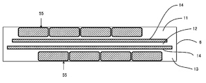
- the support plate 6 has a configuration in which a front plate 11, a middle plate 12, and a back plate 13 are polymerized.
- the front plate 11 and the back plate 13 are made of synthetic resin, and the middle plate 12 is made of ceramic. That is, the magnetic flux from the charging coil 8 can pass through the support plate 6 in the direction of the mobile terminal 15.
- position detection coils 14 (an example of a charging coil position detection unit) shown in FIGS. 10 and 11 are provided in the Y direction and the X direction.
- the position detection coil 14 is extended in the Y direction by 10 or more (Y1, Y2, Y3, Y4, Y5, Y6...) And extended in the X direction.
- three (X 1, X 2, X 3) are provided so as to intersect the Y direction and the X direction at a predetermined interval above and below the middle plate 12 of the support plate 6.
- the position detection coil 14 is used in Patent Document 2, and detects at which position of the mobile terminal installation portion on the upper surface of the support plate 6 the mobile terminal 15 is placed as shown in FIG.
- the position detection coil 14 is used to detect at which position on the upper surface of the support plate 6 the portable terminal 15 is placed as shown in FIG. It moves to the position which opposes the terminal charging coil (15a of FIG. 14) of the portable terminal 15, and it is the structure which energizes the charging coil 8 after that.
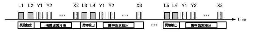
- four foreign matter detection coils 55 (L 1, L 2, L 3, L 4) extending in the Y direction are close to the surface side (upper surface side) of the surface plate 11. Further, the four foreign matter detection coils 55 (L5, L6, L7, L8) in the Y direction are arranged close to each other on the back surface side (lower surface side) of the back plate 13 as well.
- these foreign object detection coils 55 are dividedly driven (L1 and L2 are driven, L3 and L4 are driven, L5 and L6 are driven, and L7 and L8 are driven), thereby charging coils. 8 is de-energized (before the charging coil 8 is energized), it is detected whether or not foreign matter is present on the surface side (upper surface side) of the surface plate 11. The operation will be described in detail below.
- the charging coil 8 is formed in an annular shape in which a wire is wound in a spiral shape, and the outer peripheral side and the lower surface side thereof are made of a synthetic resin holder 16. It is held in a state covered by.
- support legs 17 extending downward from the charging coil 8 are integrally formed of synthetic resin on the lower surface of the holding body 16.
- a control board 19 and a lower face plate 20 of the main body case 7 are disposed below the support board 18, and the control board 19 passes between the lower face of the support board 18 and the upper face of the lower face plate 20.
- the support 21 is provided. That is, in the present embodiment, the lower surface side of the support plate 18 is supported on the lower surface plate 20 of the main body case 7 via the support body 21 in order to increase the strength against excessive weight.
- the drive unit 9 includes an X-axis direction drive shaft 22 and a Y-axis direction drive shaft 23, and the X-axis direction drive shaft 22 and the Y-axis direction drive shaft 23 Each intermediate portion is engaged with the holding body 16 outside the charging coil holding portion of the holding body 16.
- a through hole (not shown) through which the X-axis direction drive shaft 22 penetrates and a through hole 24 through which the Y-axis direction drive shaft 23 penetrates are crossed at a predetermined interval in the vertical direction.
- a worm wheel 25 is provided on one end side of the X-axis direction drive shaft 22, a gear 26 is provided on one end, and a gear 26 is provided on the other end.
- the worm wheel 25 is engaged with the worm 27, and the worm 27 is connected to the motor 28.
- gears 26 on both sides are engaged with the gear plate 29, respectively.
- a worm wheel 30 is provided at one end side of the Y-axis direction drive shaft 23, a gear 31 is provided at one end, and a gear 31 is provided at the other end.
- the worm wheel 30 is engaged with the worm 32, and the worm 32 is connected to the motor 33.
- gears 31 on both sides are engaged with the gear plate 34, respectively.
- a motor 28 is connected to the control unit 10 via an X-axis motor control unit 36, and a motor 33 is connected to the control unit 10 via a Y-axis motor control unit 37.
- the charging coil 8 is connected to the control unit 10 via the charging coil control unit 38, and the position detection coil 14 is further connected via the position detection coil control unit 39.
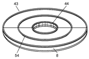
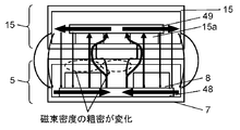
- the charging coil 8 is movable according to the place where the portable terminal 15 is placed, so that the detection coils 43 and 44 are arranged on the upper surface (support plate) of the charging coil 8. 6 side surfaces) and is configured to be movable together with the charging coil 8.
- the large-diameter detection coil 43 is approximately the same size as the outer diameter of the annular charging coil 8 (slightly smaller than the outer diameter of the charging coil 8), and the small-diameter detection coil 44 is an annular charging coil. The size was approximately the same as the inner diameter of the coil 8 (slightly larger than the inner diameter of the charging coil 8).
- the large-diameter detection coil 43 and the small-diameter detection coil 44 were connected to the control unit 10 through voltage detection units 45 and 46, respectively, as shown in FIG.
- reference numeral 47 in FIG. 9 denotes a memory in which a program for performing a safe operation on a metallic foreign object using the large-diameter detection coil 43 and the small-diameter detection coil 44 is stored.
- the magnetic flux in the inner part of the charging coil 8 decreases, and conversely, the outer magnetic flux. Is detected, and the state is detected by the large-diameter detection coil 43 and the small-diameter detection coil 44.
- FIGS. 13 to 18 are simplified for easy understanding.
- the mobile terminal 15 is charged (while the charging coil 8 is energized) in a state where there is no metallic foreign object between the mobile terminal installation portion (upper surface of the support plate 6) and the mobile terminal 15. It shows the state.
- reference numeral 48 denotes a magnetic material for forming a magnetic path provided on the lower side of the charging coil 8 (on the opposite side to the portable terminal 15) in the main body case 7 of the portable terminal charging device 5.
- Reference numeral 49 denotes a magnetic material for forming a magnetic path provided in the mobile terminal 15 on the upper side of the terminal charging coil 15a (the side opposite to the mobile terminal charging device 5).
- the magnetic flux is supplied from the charging coil 8 of the mobile terminal charging device 5 to the terminal charging coil 15a of the mobile terminal 15 as shown in FIG.
- the terminal 15 is charged.
- the magnetic flux after passing through the terminal charging coil 15a portion returns to the charging coil 8 through the magnetic body 49, the space, and the magnetic body 48 as indicated by the arrows.
- FIG. 15 shows a state in which a non-magnetic metal foreign object 50 (for example, an aluminum coin) exists between the mobile terminal installation portion (upper surface of the support plate 6) and the mobile terminal 15. This shows a state in which the battery is being charged.
- a non-magnetic metal foreign object 50 for example, an aluminum coin
- the magnetic flux that becomes the counterclockwise arrow is in the direction opposite to the direction of the magnetic flux from the charging coil 8 toward the terminal charging coil 15a in the inner part (the central direction of the charging coil 8), and counterclockwise.
- the direction of the magnetic flux from the charging coil 8 toward the terminal charging coil 15a is the same direction.
- the magnetic flux traveling in the inner circumferential direction of the charging coil 8 out of the magnetic flux from the charging coil 8 toward the terminal charging coil 15 a is curved outward from the inner circumferential portion of the charging coil 8. It will head for the charging coil 15a.
- the magnetic flux in the inner peripheral portion of the charging coil 8 decreases, and conversely, the magnetic flux in the outer peripheral portion of the charging coil 8 increases.
- the large-diameter detection coil 43 on the upper surface side (terminal charging coil 15a side) of the charging coil 8 and the small-diameter detection coil 44 inside the detection coil 43 are provided. Since it is provided, the state of FIG. 16 can be detected by these detection coils 43 and 44.
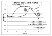
- the first voltage (V1) detected by the large-diameter detection coil 43 increases (as a result of a large amount of magnetic flux and a short distance from the magnetic flux), and conversely is detected by the small-diameter detection coil 44.
- the second voltage (V2) is smaller (the result is that the magnetic flux is less and the distance from the magnetic flux is longer).
- the peak voltage of the first voltage (V1) detected by the large diameter detection coil 43 is detected by the voltage detection unit 45, and the second voltage (V2) detected by the small diameter detection coil 44 is detected. ) Is detected by the voltage detector 46.
- the ratio (V2 / V1) of the second voltage (V2) to the first voltage (V1) is compared with a set value (stored in the memory 47, for example, 0.7) by the control unit 10. , Thereby performing safe operation.
- the second voltage (V2) detected by the small-diameter detection coil 44 is, for example, 25% compared to the state of FIG. 13 (without the metal foreign object 50). It is getting smaller.
- the first voltage (V1) detected by the large-diameter detection coil 43 is compared with the state of FIG. 13 (without the metal foreign object 50). For example, it is 170% larger.
- the ratio (V2 / V1) of the second voltage (V2) to the first voltage (V1) is as shown in FIG. 14 (without metal foreign object 50) in the state shown in FIG. 16 (with metal foreign object 50). Is less than half (0.5 or less).
- the control unit 10 detects the presence of the metal foreign object 50 when the detected value (0.5 or less) is sufficiently smaller than the set value (0.7) recorded in the memory 47, and immediately applies the charging coil 8 to the charging coil 8. The energization is stopped and the alarm device 51 shown in FIGS. 2 and 9 is operated.
- the alarm device 51 since the alarm device 51 is connected to the control unit 10 as shown in FIG. 9, when such a metal foreign object 50 is present, the alarm device 51 is lit to notify the abnormal state.
- FIG. 17 shows that charging of the mobile terminal 15 is performed in a state where a magnetic metallic foreign material 52 (for example, iron) exists between the mobile terminal installation portion (the upper surface of the support plate 6) and the mobile terminal 15. It shows the state.
- a magnetic metallic foreign material 52 for example, iron
- the metal foreign object 52 of this time is a magnetic body, a magnetic flux that has traveled in the metal foreign object 52 passes, and a magnetic flux that travels in the interior, for example, is generated. For this reason, FIG. Is different, and the magnetic flux due to eddy current is shown in double.
- the charging coil 8 to the terminal charging coil 15a in the inner part thereof (in the central direction of the charging coil 8).
- the direction of the magnetic flux toward the terminal charging coil 15a from the charging coil 8 is the direction opposite to the direction of the magnetic flux toward and the outer portion of the magnetic flux that is the counterclockwise arrow (the direction opposite to the center of the charging coil 8).
- the magnetic flux traveling in the inner circumferential direction of the charging coil 8 out of the magnetic flux from the charging coil 8 toward the terminal charging coil 15 a is curved outward from the inner circumferential portion of the charging coil 8, It goes to the charging coil 15a (a part of the outer periphery travels inside the metal foreign object 52).
- the magnetic flux in the inner peripheral portion of the charging coil 8 decreases, and conversely, the magnetic flux in the outer peripheral portion of the charging coil 8 increases.
- Such a situation can be detected by the large-diameter detection coil 43 and the small-diameter detection coil 44 on the upper surface side of the charging coil 8 (terminal charging coil 15a side).
- the first voltage (V1) detected by the large-diameter detection coil 43 increases (as a result of a large amount of magnetic flux and a short distance from the magnetic flux), and conversely is detected by the small-diameter detection coil 44.
- the second voltage (V2) is smaller (the result is that the magnetic flux is less and the distance from the magnetic flux is longer).
- the peak voltage of the first voltage (V1) detected by the large-diameter detection coil 43 is detected by the voltage detection unit 45, and the peak of the second voltage (V2) detected by the small-diameter detection coil 44 is detected.
- the voltage is detected by the voltage detection unit 46, and the ratio (V2 / V1) of the second voltage (V2) to the first voltage (V1) is stored in the memory 47 in the set value (memory 47). For example, 0.7), thereby performing a safe operation.
- the second voltage (V2) detected by the small-diameter detection coil 44 is, for example, 15% compared to the state of FIG. 14 (without the metal foreign object 52). It is getting smaller.
- the first voltage (V1) detected by the large-diameter detection coil 43 is higher than that in the state of FIG. 14 (without the metal foreign object 52). For example, it is 170% larger.
- the ratio (V2 / V1) of the second voltage (V2) to the first voltage (V1) is as shown in FIG. 14 (without the metal foreign object 52) in the state of FIG. 17 (with the metal foreign object 52). Is less than half (0.5 or less).
- the control unit 10 detects the presence of the metal foreign object 52 when the detection value (0.5 or less) is sufficiently smaller than the set value (0.7) recorded in the memory 47, and immediately applies the charging coil 8 to the charging coil 8. The energization is stopped and the alarm device 51 shown in FIGS. 2 and 9 is operated.
- the alarm device 51 is turned on to notify the abnormal state.
- charging is performed regardless of whether a non-magnetic metal foreign object 50 or a magnetic metal foreign object 52 exists between the mobile terminal installation portion (upper surface of the support plate 6) and the mobile terminal 15.
- the magnetic flux in the inner part of the coil 8 decreases, and conversely, the outer magnetic flux increases, and the state is detected by the large-diameter detection coil 43 and the small-diameter detection coil 44.
- the first voltage (V1) increases, and when the inner magnetic flux decreases, the detection is performed by the small-diameter detection coil 44. Since the second voltage (V2) is reduced, the ratio between the two voltages (V2 / V1) is sufficiently smaller than the set value, and as a result, the presence of the metal foreign objects 50 and 52 is reliably detected. Therefore, safe operation can be surely executed.
- the detection operation (determined by the ratio of V2 / V1) of such metal foreign objects 50 and 52 has a substantial influence on whether it is a magnetic body or a non-magnetic body and the type of the mobile terminal 15 to be charged. Therefore, charging of the various portable terminals 15 can be performed with versatility, and is extremely easy to use.
- the mobile terminal 15 is displaced from the support plate 6 due to the inertia in the traveling direction and vibrations during driving. Therefore, as a countermeasure, the outer peripheral portion of the support plate 6 is located more than the support plate 6 as shown in FIG. A guard portion 53 that protrudes upward is provided.
- FIG. 12 Although the example which provided the large diameter detection coil 43 and the small diameter detection coil 44 of the charging coil 8 upper surface side (terminal charging coil 15a side) was demonstrated, as shown to FIG. 12, FIG. A medium-diameter detection coil 54 may be provided between the large-diameter detection coil 43 and the small-diameter detection coil 44, and this may also be connected to the control unit 10.
- the detection coils 43, 44, and 54 to be compared can be switched, or the situation between the detection coils 43 and 54 and 54 and 44 can be detected.
- This position initialization means that the motors 28 and 33 are driven to return the charging coil 8 to the corners (coordinates xo and yo) shown in FIG.
- the switches 41 and 42 exist in the corner portion, and when the charging coil 8 moves to the corner in the main body case 7 where the switches 41 and 42 are provided, these switches 41 and 42 operate. Thus, the control unit 10 determines that the charging coil 8 has moved to the initial value.
- the control unit 10 supplies detection pulses to the eight foreign object detection coils 55 (L1, L2, L3, L4, L5, L6, L7, and L8).
- the resonance frequency of each foreign object detection coil 55 becomes lower than the reference resonance frequency for each location of the charging coil 8 stored in the memory 47, or the resonance voltage detected by each foreign object detection coil 55 is When it becomes higher than the reference resonance voltage for each location of the charging coil 8 stored in the memory 47, a safe operation is executed (S3 and S4 in FIG. 19).
- FIG. 20 shows a state where the resonance frequency of the foreign object detection coil 55 corresponding to the location of the charging coil 8 is affected.
- the A line in FIG. 20 indicates each foreign object detection coil 55 (L1, L2, L3, L4, L5, L6, L7, L8) when the charging coil 8 exists at the coordinates (10, 0).
- the resonance frequency of the foreign object detection coil 55 (L8) in the vicinity of the charging coil 8 is reduced.
- line B in FIG. 20 shows resonance of each foreign object detection coil 55 (L1, L2, L3, L4, L5, L6, L7, L8) when the charging coil 8 is present at coordinates (10, 35). The frequency is shown and the situation where the resonant frequency of the foreign object detection coil 55 (L5) in the vicinity of the charging coil 8 is lowered is shown.
- the A line in FIG. 21 shows the resonance voltage of each foreign object detection coil 55 when the charging coil 8 exists at the coordinates (10, 0).
- the foreign object detection coil 55 ( The situation where the resonance voltage of L8) is increasing is shown.
- line B in FIG. 22 shows each foreign object detection coil 55 when the charging coil 8 is present at coordinates (10, 0) and a metal foreign object is present near the fourth foreign object detection coil 55.
- the resonance frequency of the foreign object detection coil 55 (L4) in the vicinity of the charging coil 8 is high.
- the A line in FIG. 23 shows the resonance voltage of each foreign object detection coil 55 when the charging coil 8 is present at the coordinates (10, 0) and there is no metallic foreign object.
- line B in FIG. 23 shows the state of each foreign object detection coil 55 when the charging coil 8 is present at the coordinates (10, 0) and the metal foreign object is present in the fourth foreign object detection coil 55.
- the resonance voltage is shown, and the situation where the resonance voltage of the foreign object detection coil 55 (L4) in the vicinity of the charging coil 8 is low is shown.
- the foreign object detection coil 55 tries to detect a metal foreign object.
- the memory 47 stores a reference resonance frequency and a reference resonance voltage of each foreign object detection coil 55 for each location where the charging coil 8 exists.
- control unit 10 first detects that the position detection coil 14 (an example of the charging coil position detection unit) or the charging coil 8 has returned to the corners (coordinates xo, yo) shown in FIG. , 42 detects the location of the charging coil 8.
- the foreign object detection coil 55 tries to detect a metal foreign object without being affected by the charging coil 8.
- the resonance frequency detected by the eight foreign object detection coils 55 increases by a predetermined value or more than the resonance frequency stored in the memory 47 in advance, or eight foreign object detections are detected.
- the resonance voltage detected by the coil 55 drops by a predetermined value or more than the resonance voltage stored in the memory 47 in advance, the presence of a foreign object is confirmed, and as a result, a safe operation is executed (see FIG. 19 S3, S4).
- the safe operation when the charging coil 8 is not energized is based on the alarm 51. However, if the metal foreign matter is not removed thereafter, the charging coil 8 may not be energized.
- the location of the mobile terminal 15 is detected by the position detection coil 14 ( S5 in FIG. 19).
- the charging coil 8 is moved to the place by the drive unit 9 (S6 in FIG. 19).
- energization of the charging coil 8 S7 in FIG. 19
- foreign object detection by the large diameter detection coil 43 provided on the upper surface side (terminal charging coil 15a side) of the charging coil 8 and the small diameter detection coil 44 The operation is executed (S8 in FIG. 19).
- the control unit 10 issues an alarm by the alarm device 51 and stops charging the charging coil 8 as a safe operation (S9 in FIG. 19).
- the next portable terminal 15 may continue to be placed on the upper surface of the support plate 6. Therefore, here, the position of the charging coil 8 is stored in the memory 47 (FIG. 19 S11), charging is terminated (S12 in FIG. 19).
- the control unit 10 detects the foreign matter by the foreign matter detection coil 55 and detects the position of the charging coil 8 by the position detection coil 14 and the switches 41 and 42 ( The position of the portable terminal 15 on the upper surface of the support plate 6) is alternately repeated.
- the position detection coil 14 is driven by driving a part of 55 (L1, L2, L3, L4, L5, L6, L7, L8) of the plurality of foreign matter detection coils as can be understood from FIG. Then, after detecting the foreign matter, the operation of driving the plurality of position detection coils 14 (Y1 to X3) to detect the location where the charging coil 8 is present is alternately executed.
- the foreign matter detection coil 55 is divided and driven (L1 and L2 are driven), so that the surface side of the surface plate 11 (before the charging coil 8 is energized) (when the charging coil 8 is not energized) It is configured to detect whether or not a foreign substance is present on the upper surface side, and thereafter, a plurality of position detection coils 14 (Y1 to Y6,..., X1 to X3) are driven to charge coils. The operation of detecting the location of 8 is executed.
- the foreign matter detection coil 55 is divided and driven (L3 and L4 are driven), so that the surface side (upper surface side) of the surface plate 11 is not energized to the charging coil 8 (before energization to the charging coil 8). )
- the plurality of position detection coils 14 (Y1 to Y6,..., X1 to X3) are driven to The operation of detecting the location is executed.
- the foreign matter detection coil 55 is dividedly driven (L5 and L6 are driven), so that when the charging coil 8 is not energized (before the charging coil 8 is energized), ) To detect whether or not a foreign object is present, and thereafter, the plurality of position detection coils 14 (Y1 to Y6,..., X1 to X3) are driven to The operation of detecting the location is executed.
- the foreign matter detection coil 55 is divided and driven (L7 and L8 are driven), so that the surface side (upper surface side) of the surface plate 11 is not energized to the charging coil 8 (before energization to the charging coil 8).
- the plurality of position detection coils 14 (Y1 to Y6,..., X1 to X3) are driven to The operation of detecting the location is executed.
- the position of the portable terminal 15 is detected by a plurality of position detection coils 14 (Y1 to Y6,..., X1 to X3) at that time, The charging coil 8 is moved to a position opposite to, and charging is started.
- the foreign object detection before energization of the charging coil 8 can be a simple type in which a part of the plurality of foreign object detection coils 55 is driven to detect the foreign object.
- the time required for foreign object detection before the start can be shortened, whereby the time until the charging coil is started to be charged can be shortened.
- the operation of driving the plurality of position detection coils 14 (Y1 to Y6,..., X1 to X3) to detect the location where the charging coil 8 is present can be determined from the information of one pulse. Time will be short.
- the portable terminal charging device according to the present invention is easy to use, and can detect foreign objects reliably and has high safety. Therefore, it is expected to be used as a mobile terminal charging device for in-vehicle use or home use.
Landscapes
- Engineering & Computer Science (AREA)
- Power Engineering (AREA)
- Computer Networks & Wireless Communication (AREA)
- Charge And Discharge Circuits For Batteries Or The Like (AREA)
Abstract
Description
2 車室
3 ハンドル
4 電子機器
5 携帯端末充電装置
6 支持板
7 本体ケース
8 充電コイル
9 駆動部
10 制御部
11 表面板
12 中板
13 裏面板
14 位置検出コイル
15 携帯端末
15a 端末充電コイル
16 保持体
17 支持脚
18 支持板
19 制御基板
20 下面板
21 支持体
22 X軸方向駆動軸
23 Y軸方向駆動軸
24 貫通孔
25 ウォームホイール
26 ギア
27 ウォーム
28 モータ
29 歯車板
30 ウォームホイール
31 ギア
32 ウォーム
33 モータ
34 歯車板
35 フレキシブル配線
36 X軸モータ制御部
37 Y軸モータ制御部
38 充電コイル制御部
39 位置検出コイル制御部
40 電源スイッチ
41 スイッチ
42 スイッチ
43 検出コイル
44 検出コイル
45 電圧検出部
46 電圧検出部
47 メモリ
48 磁性体
49 磁性体
50 金属異物
51 警報機
52 金属異物
53 ガード部
54 検出コイル
55 異物検出コイル
Claims (13)
- 表面側が携帯端末設置部となった支持板と、
前記支持板の裏面側において、前記支持板に対向した状態で可動自在に配置された充電コイルと、
前記充電コイルを支持板の裏面側において移動可能な駆動部と、
前記充電コイル、前記駆動部に接続された制御部と、
前記制御部に接続されたメモリと、
前記支持板に設けられ、前記制御部にそれぞれ接続された複数の異物検出コイルと複数の位置検出コイルと、
を備え、
前記充電コイルには、第1の検出コイルと、前記第1の検出コイルの内方に配置され、かつ、前記第1の検出コイルよりも小径の第2の検出コイルが設けられるとともに、
前記第1、第2の検出コイルは前記制御部に接続され、
前記メモリには、前記充電コイルの存在場所における前記各異物検出コイルの基準共振周波数、または基準共振電圧を格納し、
前記制御部は、
前記充電コイルへの通電前の状態では、前記複数の異物検出コイルの一部を駆動して異物検出を行った後に、前記複数の位置検出コイルを駆動して前記充電コイルの存在場所を検出する動作を交互に実行し、
前記異物検出コイルによる異物検出時には、前記充電コイルの存在場所に対応する前記複数の異物検出コイルの1つが検出した共振周波数が、前記メモリに格納された基準共振周波数よりも高くなった場合、または、前記充電コイルの存在場所に対応する前記複数の異物検出コイルの1つが検出した共振電圧が、前記メモリに格納された基準共振電圧よりも低くなった場合、安全動作を実行させ、
前記位置検出コイルにより前記充電コイルの存在場所を検出した場合は、前記充電コイルに通電し、前記充電コイルへの通電後には、前記第1の検出コイルで検出される第1の電圧(V1)に対する、前記第2の検出コイルで検出される第2の電圧(V2)の比(V2/V1)が、設定値よりも小さくなると、安全動作を実行させる、
携帯端末充電装置。 - 前記制御部は、複数回目の異物検出コイル駆動時には、前回駆動した異物検出コイルとは別の異物検出コイルを駆動する、
請求項1に記載の携帯端末充電装置。 - 前記複数の異物検出コイルのうち、2つ以上は前記支持板の表面に設けられ、他の2つ以上は前記支持板の裏面に設けられた、
請求項1に記載の携帯端末充電装置。 - 前記制御部に接続された警報機をさらに備え、
前記制御部は、安全動作として前記警報機から警報を発令する、
請求項1に記載の携帯端末充電装置。 - 前記充電コイルは、線材をスパイラル状に巻きつけた環状形状を有し、前記第1、第2の検出コイルは前記充電コイルにおける前記支持板に対向する面に配置された、
請求項1に記載の携帯端末充電装置。 - 前記第1の検出コイルの外径は、前記充電コイルの外径と実質的に同じであり、前記第2の検出コイルの外径は前記充電コイルの内径と実質的に同じである、
請求項1に記載の携帯端末充電装置。 - 前記第1の検出コイルと前記第2の検出コイルとの間に配置された第3の検出コイルをさらに備えた、
請求項1に記載の携帯端末充電装置。 - 前記制御部は、前記第1の電圧(V1)に対する、前記第2の電圧(V2)の前記比(V2/V1)が、設定値よりも小さくなると、安全動作として、前記充電コイルへの通電を遮断する、
請求項1に記載の携帯端末充電装置。 - 前記制御部に接続された警報機をさらに備え、
前記制御部は、前記第1の電圧(V1)に対する、前記第2の電圧(V2)の前記比(V2/V1)が、設定値よりも小さくなると、安全動作として、前記制御部に接続された前記警報機を動作させる、
請求項1に記載の携帯端末充電装置。 - 前記制御部に接続されるとともに、前記第1、第2検出コイルにそれぞれ接続され、ピーク電圧を測定する電圧検出部をさらに備えた、
請求項1に記載の携帯端末充電装置。 - 前記制御部は、前記充電コイルへの充電後には、前記メモリに、前記充電コイルの存在場所を記録する、
請求項1に記載の携帯端末充電装置。 - 車室と、
前記携帯端末設置部を上に向けて前記車室内に配置された請求項1~11のいずれか一つに記載の携帯端末充電装置と、を備えた、
自動車。 - 前記支持板の外周部には、前記支持板よりも上方に突出したガード部が設けられた、
請求項12に記載の自動車。
Priority Applications (4)
| Application Number | Priority Date | Filing Date | Title |
|---|---|---|---|
| EP15769939.8A EP3131179B1 (en) | 2014-03-24 | 2015-03-11 | Mobile terminal charging device and vehicle mounted with same |
| JP2016509981A JP6340602B2 (ja) | 2014-03-24 | 2015-03-11 | 携帯端末充電装置と、それを搭載した自動車 |
| CN201580015817.9A CN106134030B (zh) | 2014-03-24 | 2015-03-11 | 便携式终端充电装置和搭载其的汽车 |
| US15/127,114 US20170117740A1 (en) | 2014-03-24 | 2015-03-11 | Mobile terminal charging device and vehicle mounted with same |
Applications Claiming Priority (2)
| Application Number | Priority Date | Filing Date | Title |
|---|---|---|---|
| JP2014059570 | 2014-03-24 | ||
| JP2014-059570 | 2014-03-24 |
Publications (1)
| Publication Number | Publication Date |
|---|---|
| WO2015146030A1 true WO2015146030A1 (ja) | 2015-10-01 |
Family
ID=54194584
Family Applications (1)
| Application Number | Title | Priority Date | Filing Date |
|---|---|---|---|
| PCT/JP2015/001332 Ceased WO2015146030A1 (ja) | 2014-03-24 | 2015-03-11 | 携帯端末充電装置と、それを搭載した自動車 |
Country Status (5)
| Country | Link |
|---|---|
| US (1) | US20170117740A1 (ja) |
| EP (1) | EP3131179B1 (ja) |
| JP (1) | JP6340602B2 (ja) |
| CN (1) | CN106134030B (ja) |
| WO (1) | WO2015146030A1 (ja) |
Cited By (1)
| Publication number | Priority date | Publication date | Assignee | Title |
|---|---|---|---|---|
| JP2020039245A (ja) * | 2018-09-04 | 2020-03-12 | ヒタチ−エルジー データ ストレージ コリア,インコーポレイティド | 無線で電力を伝送する装置と方法 |
Families Citing this family (4)
| Publication number | Priority date | Publication date | Assignee | Title |
|---|---|---|---|---|
| EP3032687B1 (en) * | 2013-07-18 | 2017-11-29 | Panasonic Intellectual Property Management Co., Ltd. | Contactless charger, program therefor, and automobile equipped with same |
| CN110571948B (zh) * | 2019-08-01 | 2023-04-11 | 华为技术有限公司 | 无线充电系统的异物检测装置、方法及无线充电系统 |
| US10868436B1 (en) * | 2019-10-02 | 2020-12-15 | Kingston Technology Corporation | Mobile device gaming accessory with swappable battery packs and wireless charging |
| CN111293789B (zh) * | 2020-02-19 | 2022-04-08 | 华为技术有限公司 | 检测装置及方法、无线电能发射装置、无线电能接收装置 |
Citations (3)
| Publication number | Priority date | Publication date | Assignee | Title |
|---|---|---|---|---|
| JP2009247194A (ja) * | 2007-12-18 | 2009-10-22 | Sanyo Electric Co Ltd | 充電台 |
| JP2013192391A (ja) * | 2012-03-14 | 2013-09-26 | Sony Corp | 検知装置、受電装置、送電装置及び非接触給電システム |
| JP2013240235A (ja) * | 2012-05-17 | 2013-11-28 | Sony Corp | 受電装置、および、給電システム |
Family Cites Families (22)
| Publication number | Priority date | Publication date | Assignee | Title |
|---|---|---|---|---|
| US8169185B2 (en) * | 2006-01-31 | 2012-05-01 | Mojo Mobility, Inc. | System and method for inductive charging of portable devices |
| US20110050164A1 (en) * | 2008-05-07 | 2011-03-03 | Afshin Partovi | System and methods for inductive charging, and improvements and uses thereof |
| JP2009273327A (ja) * | 2008-05-10 | 2009-11-19 | Sanyo Electric Co Ltd | 電池内蔵機器と充電台 |
| JP5605153B2 (ja) * | 2010-10-15 | 2014-10-15 | ソニー株式会社 | 給電装置、給電方法および給電システム |
| JP2013135599A (ja) * | 2011-12-27 | 2013-07-08 | Sanyo Electric Co Ltd | 無接点充電方法 |
| CN106887883B (zh) * | 2012-02-29 | 2019-08-23 | 松下知识产权经营株式会社 | 充电装置 |
| JP2013223253A (ja) * | 2012-04-12 | 2013-10-28 | Tokai Rika Co Ltd | ホルダー |
| US9755437B2 (en) * | 2012-04-25 | 2017-09-05 | Nokia Technologies Oy | Method, apparatus, and computer program product for wireless charging detection |
| US9726518B2 (en) * | 2012-07-13 | 2017-08-08 | Qualcomm Incorporated | Systems, methods, and apparatus for detection of metal objects in a predetermined space |
| US20140191568A1 (en) * | 2013-01-04 | 2014-07-10 | Mojo Mobility, Inc. | System and method for powering or charging multiple receivers wirelessly with a power transmitter |
| US10075025B2 (en) * | 2013-06-19 | 2018-09-11 | Renesas Electronics Corporation | Power transmission device, wireless power feeding system, and control method |
| DE102013212588B4 (de) * | 2013-06-28 | 2023-10-12 | Robert Bosch Gmbh | Verfahren zur Fremdobjekterkennung bei einer Induktionsladevorrichtung |
| US9893557B2 (en) * | 2013-07-12 | 2018-02-13 | Schneider Electric USA, Inc. | Method and device for foreign object detection in induction electric charger |
| EP3032687B1 (en) * | 2013-07-18 | 2017-11-29 | Panasonic Intellectual Property Management Co., Ltd. | Contactless charger, program therefor, and automobile equipped with same |
| EP3032699B1 (en) * | 2013-07-31 | 2018-10-10 | Panasonic Corporation | Wireless electricity transmission device and wireless power transmission system |
| JP6052804B2 (ja) * | 2013-08-27 | 2016-12-27 | オムロンオートモーティブエレクトロニクス株式会社 | 携帯端末、通報制御方法、及び、通報システム |
| US9985463B2 (en) * | 2013-11-01 | 2018-05-29 | Panasonic Intellectual Property Management Co., Ltd. | Mobile terminal charging device and vehicle equipped with same |
| EP3086436B1 (en) * | 2013-12-16 | 2018-04-18 | Panasonic Intellectual Property Management Co., Ltd. | Contactless charging device, program therefor, and automobile having contactless charging device mounted therein |
| EP3121924B1 (en) * | 2013-12-25 | 2019-04-03 | Panasonic Intellectual Property Management Co., Ltd. | Portable terminal charging apparatus and automobile having portable terminal charging apparatus mounted therein |
| WO2015177994A1 (ja) * | 2014-05-19 | 2015-11-26 | パナソニックIpマネジメント株式会社 | 携帯端末充電装置と、それを搭載した自動車 |
| DE102016103044A1 (de) * | 2016-02-22 | 2017-08-24 | Ipt Technology Gmbh | Verfahren zur Erkennung eines elektrisch leitfähigen Fremdkörpers |
| US10097922B2 (en) * | 2016-02-26 | 2018-10-09 | Zagg Amplified, Inc. | Portable speaker with features for vehicle integration and system |
-
2015
- 2015-03-11 US US15/127,114 patent/US20170117740A1/en not_active Abandoned
- 2015-03-11 EP EP15769939.8A patent/EP3131179B1/en active Active
- 2015-03-11 JP JP2016509981A patent/JP6340602B2/ja active Active
- 2015-03-11 WO PCT/JP2015/001332 patent/WO2015146030A1/ja not_active Ceased
- 2015-03-11 CN CN201580015817.9A patent/CN106134030B/zh active Active
Patent Citations (3)
| Publication number | Priority date | Publication date | Assignee | Title |
|---|---|---|---|---|
| JP2009247194A (ja) * | 2007-12-18 | 2009-10-22 | Sanyo Electric Co Ltd | 充電台 |
| JP2013192391A (ja) * | 2012-03-14 | 2013-09-26 | Sony Corp | 検知装置、受電装置、送電装置及び非接触給電システム |
| JP2013240235A (ja) * | 2012-05-17 | 2013-11-28 | Sony Corp | 受電装置、および、給電システム |
Cited By (2)
| Publication number | Priority date | Publication date | Assignee | Title |
|---|---|---|---|---|
| JP2020039245A (ja) * | 2018-09-04 | 2020-03-12 | ヒタチ−エルジー データ ストレージ コリア,インコーポレイティド | 無線で電力を伝送する装置と方法 |
| JP7348741B2 (ja) | 2018-09-04 | 2023-09-21 | ヒタチ-エルジー データ ストレージ コリア,インコーポレイティド | 無線で電力を伝送する装置と方法 |
Also Published As
| Publication number | Publication date |
|---|---|
| JP6340602B2 (ja) | 2018-06-13 |
| US20170117740A1 (en) | 2017-04-27 |
| EP3131179A4 (en) | 2017-03-15 |
| EP3131179B1 (en) | 2019-05-08 |
| EP3131179A1 (en) | 2017-02-15 |
| JPWO2015146030A1 (ja) | 2017-04-13 |
| CN106134030B (zh) | 2019-03-15 |
| CN106134030A (zh) | 2016-11-16 |
Similar Documents
| Publication | Publication Date | Title |
|---|---|---|
| JP6467639B2 (ja) | 携帯端末充電装置と、それを搭載した自動車 | |
| JPWO2015098038A1 (ja) | 携帯端末充電装置と、それを搭載した自動車 | |
| JP6515349B2 (ja) | 携帯端末充電装置と、それを搭載した自動車 | |
| JP6340602B2 (ja) | 携帯端末充電装置と、それを搭載した自動車 | |
| US10090718B2 (en) | Contactless charging device, program therefor, and automobile having contactless charging device mounted therein | |
| JP6364625B2 (ja) | 無接点充電装置と、そのプログラム、およびそれを搭載した自動車 | |
| US9859730B2 (en) | Mobile terminal charger and vehicle equipped with same | |
| WO2013172016A1 (ja) | 携帯端末充電装置及び自動車 | |
| JP6311132B2 (ja) | 携帯端末充電装置と、それを搭載した自動車 | |
| JP2014166130A (ja) | 携帯端末充電装置と、それを用いた自動車 | |
| JP2013243906A (ja) | 携帯端末充電装置と、それを用いた自動車 |
Legal Events
| Date | Code | Title | Description |
|---|---|---|---|
| 121 | Ep: the epo has been informed by wipo that ep was designated in this application |
Ref document number: 15769939 Country of ref document: EP Kind code of ref document: A1 |
|
| REEP | Request for entry into the european phase |
Ref document number: 2015769939 Country of ref document: EP |
|
| WWE | Wipo information: entry into national phase |
Ref document number: 2015769939 Country of ref document: EP |
|
| ENP | Entry into the national phase |
Ref document number: 2016509981 Country of ref document: JP Kind code of ref document: A |
|
| WWE | Wipo information: entry into national phase |
Ref document number: 15127114 Country of ref document: US |
|
| NENP | Non-entry into the national phase |
Ref country code: DE |