WO2015146073A1 - プロジェクター - Google Patents
プロジェクター Download PDFInfo
- Publication number
- WO2015146073A1 WO2015146073A1 PCT/JP2015/001484 JP2015001484W WO2015146073A1 WO 2015146073 A1 WO2015146073 A1 WO 2015146073A1 JP 2015001484 W JP2015001484 W JP 2015001484W WO 2015146073 A1 WO2015146073 A1 WO 2015146073A1
- Authority
- WO
- WIPO (PCT)
- Prior art keywords
- image
- display
- optical system
- projector
- projection
- Prior art date
- Legal status (The legal status is an assumption and is not a legal conclusion. Google has not performed a legal analysis and makes no representation as to the accuracy of the status listed.)
- Ceased
Links
Images


Classifications
-
- G—PHYSICS
- G03—PHOTOGRAPHY; CINEMATOGRAPHY; ANALOGOUS TECHNIQUES USING WAVES OTHER THAN OPTICAL WAVES; ELECTROGRAPHY; HOLOGRAPHY
- G03B—APPARATUS OR ARRANGEMENTS FOR TAKING PHOTOGRAPHS OR FOR PROJECTING OR VIEWING THEM; APPARATUS OR ARRANGEMENTS EMPLOYING ANALOGOUS TECHNIQUES USING WAVES OTHER THAN OPTICAL WAVES; ACCESSORIES THEREFOR
- G03B21/00—Projectors or projection-type viewers; Accessories therefor
- G03B21/005—Projectors using an electronic spatial light modulator but not peculiar thereto
-
- G—PHYSICS
- G03—PHOTOGRAPHY; CINEMATOGRAPHY; ANALOGOUS TECHNIQUES USING WAVES OTHER THAN OPTICAL WAVES; ELECTROGRAPHY; HOLOGRAPHY
- G03B—APPARATUS OR ARRANGEMENTS FOR TAKING PHOTOGRAPHS OR FOR PROJECTING OR VIEWING THEM; APPARATUS OR ARRANGEMENTS EMPLOYING ANALOGOUS TECHNIQUES USING WAVES OTHER THAN OPTICAL WAVES; ACCESSORIES THEREFOR
- G03B21/00—Projectors or projection-type viewers; Accessories therefor
- G03B21/14—Details
- G03B21/142—Adjusting of projection optics
-
- G—PHYSICS
- G03—PHOTOGRAPHY; CINEMATOGRAPHY; ANALOGOUS TECHNIQUES USING WAVES OTHER THAN OPTICAL WAVES; ELECTROGRAPHY; HOLOGRAPHY
- G03B—APPARATUS OR ARRANGEMENTS FOR TAKING PHOTOGRAPHS OR FOR PROJECTING OR VIEWING THEM; APPARATUS OR ARRANGEMENTS EMPLOYING ANALOGOUS TECHNIQUES USING WAVES OTHER THAN OPTICAL WAVES; ACCESSORIES THEREFOR
- G03B21/00—Projectors or projection-type viewers; Accessories therefor
- G03B21/14—Details
- G03B21/147—Optical correction of image distortions, e.g. keystone
-
- H—ELECTRICITY
- H04—ELECTRIC COMMUNICATION TECHNIQUE
- H04N—PICTORIAL COMMUNICATION, e.g. TELEVISION
- H04N9/00—Details of colour television systems
- H04N9/12—Picture reproducers
- H04N9/31—Projection devices for colour picture display, e.g. using electronic spatial light modulators [ESLM]
- H04N9/3141—Constructional details thereof
- H04N9/315—Modulator illumination systems
- H04N9/3161—Modulator illumination systems using laser light sources
-
- H—ELECTRICITY
- H04—ELECTRIC COMMUNICATION TECHNIQUE
- H04N—PICTORIAL COMMUNICATION, e.g. TELEVISION
- H04N9/00—Details of colour television systems
- H04N9/12—Picture reproducers
- H04N9/31—Projection devices for colour picture display, e.g. using electronic spatial light modulators [ESLM]
- H04N9/3141—Constructional details thereof
- H04N9/317—Convergence or focusing systems
-
- G—PHYSICS
- G03—PHOTOGRAPHY; CINEMATOGRAPHY; ANALOGOUS TECHNIQUES USING WAVES OTHER THAN OPTICAL WAVES; ELECTROGRAPHY; HOLOGRAPHY
- G03B—APPARATUS OR ARRANGEMENTS FOR TAKING PHOTOGRAPHS OR FOR PROJECTING OR VIEWING THEM; APPARATUS OR ARRANGEMENTS EMPLOYING ANALOGOUS TECHNIQUES USING WAVES OTHER THAN OPTICAL WAVES; ACCESSORIES THEREFOR
- G03B21/00—Projectors or projection-type viewers; Accessories therefor
- G03B21/14—Details
- G03B21/20—Lamp housings
- G03B21/2006—Lamp housings characterised by the light source
- G03B21/2033—LED or laser light sources
-
- G—PHYSICS
- G03—PHOTOGRAPHY; CINEMATOGRAPHY; ANALOGOUS TECHNIQUES USING WAVES OTHER THAN OPTICAL WAVES; ELECTROGRAPHY; HOLOGRAPHY
- G03B—APPARATUS OR ARRANGEMENTS FOR TAKING PHOTOGRAPHS OR FOR PROJECTING OR VIEWING THEM; APPARATUS OR ARRANGEMENTS EMPLOYING ANALOGOUS TECHNIQUES USING WAVES OTHER THAN OPTICAL WAVES; ACCESSORIES THEREFOR
- G03B21/00—Projectors or projection-type viewers; Accessories therefor
- G03B21/54—Accessories
- G03B21/56—Projection screens
- G03B21/60—Projection screens characterised by the nature of the surface
- G03B21/606—Projection screens characterised by the nature of the surface for relief projection
Definitions
- the present invention relates to a projector capable of performing projection at different positions in the depth direction.
- the conventional projector uses a projection optical system that magnifies and projects an image on a flat display element. Therefore, a plane to be focused is substantially a plane, and only adjustment for moving the plane back and forth can be performed. That is, projection can not be performed simultaneously in parallel to different depth spaces, and there is no projector that can, for example, project on a curved screen in a focused state or cope with such a change in the shape of the curved screen.
- Patent Document 1 As an imaging device, there is a technique for acquiring information on the incident direction of light incident on a two-dimensional sensor, and simultaneously capturing an object at different distances in the depth direction (Patent Document 1).
- the present invention has been made in view of the above background art, and an object of the present invention is to provide a projector capable of performing projection in parallel to different positions in the depth direction.
- a plurality of display units for forming a collimated image light beam and a superimposing optical system for overlapping image light beams emitted from the plurality of display units without condensing light beams
- a projection optical system for projecting an image corresponding to the image light beam superimposed by the superposition optical system, and emitting the image light beam from the local image source area set for each of the plurality of display units.
- a display control unit configured to set overlapping positions at a plurality of different overlapping positions in the optical axis direction.
- the projection optical system projects the image superimposed by the superposition optical system
- the display control unit sets the positions on which the image light beam is superimposed to a plurality of different superposition positions in the optical axis direction.
- the projection can be performed simultaneously and in parallel to different depth spaces.
- the superimposed position of the image light beam and the projection position are in a conjugate relationship, and by adjusting the superimposed position, it is possible to adjust the position of the projection position in the optical axis direction.
- the superposing optical system superimposes the image light rays such that the image light rays passing through the plurality of lens elements and the plurality of lens elements respectively facing the plurality of display units are collected.
- a superimposing lens In this case, the convergence of the image rays from each display unit can be adjusted by each lens element, and the image rays from a plurality of display units can be superimposed so as to be collected by a superimposing lens.
- the center of the image source area is shifted from the reference standard position serving as the reference in each display unit in accordance with the relative arrangement of the display units and the setting of the overlapping position. Set to position. In this case, by shifting the center of the image source area, it is possible to set the superposition position relatively easily.
- the shift amount from the standard position of the center of the image source area is substantially proportional to the distance from the center of the optical axis of the superimposed optical system to the center of each display unit. Do. In this case, the image rays from each display unit can be collected at exactly one place.
- the plurality of images displayed on the plurality of display units are obtained by modifying the basic image in accordance with the deviation from the center.
- the image formed at the superimposed position can be made sharp with less blurring.
- the superposition position is a conjugate position of each display unit with respect to the superposition optical system.
- the plurality of display portions correspond to a plurality of portions formed on a single display element or a plurality of display elements.
- the plurality of display units include a transmissive display element and an illumination unit that illuminates the display element.
- a small display unit can form a bright image and can project a bright image.
- the illumination unit comprises a surface emitting laser.
- the collimated illumination light can be emitted from the small-sized illumination unit, and the collimated image light beam can be easily emitted from the transmissive display element.
- the plurality of display units have a light beam selection unit having a pinhole array sandwiched between a pair of lens arrays, and the image light rays collimated by the light beam selection unit are selectively selected. Let it pass. In this case, the image rays can be more precisely collimated.
- the display control unit changes the overlapping position in a time-division manner to set the projection position by the projection optical system as a three-dimensional range.
- an image can be projected on the surface of a three-dimensional shape.
- the display control unit displays a moving image in the image source region of the plurality of display units.
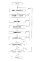
- FIG. 5 is a flowchart illustrating an overview of the operation of the projector. It is a figure explaining the projector of a 2nd embodiment. It is a figure explaining the projector of 3rd Embodiment. It is a figure explaining the projector (panel) of a modification.
- the projector 2 includes an optical system portion 50 for projecting image light, and a circuit device 80 for controlling the operation of the optical system portion 50.
- the optical system portion 50 includes the illumination unit 10, the display device 20, the superposing optical system 30, and the projection optical system 40.
- the illumination unit 10 emits the illumination light LI precisely collimated from an emission surface 10a parallel to the XY plane perpendicular to the optical axis OA.
- the illumination light LI is emitted in the Z direction parallel to the optical axis OA as a whole or as an element.
- the illumination unit 10 includes a surface emitting laser as a light source.
- the surface emitting laser is, for example, a laser element of three or more colors including RGB arranged two-dimensionally at a pitch of several ⁇ m, and the illumination light LI emitted from the emission surface 10a has a uniform distribution in the XY plane It has become.
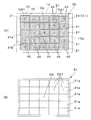
- the display device 20 has a plurality of display portions 21 arranged two-dimensionally in parallel to the XY plane.
- the display apparatus 20 has many display parts 21 arrange
- Each display unit 21 has a liquid crystal panel 21a and a light shielding frame 21b.
- the liquid crystal panel 21a is a transmission type light modulation device in which liquid crystal is sandwiched between a pair of light transmission substrates, and a polarization filter (not shown) is attached to the entrance / exit surface.
- the liquid crystal panel 21a enables two-dimensional image display by a large number of pixels, and includes a color filter for each pixel.
- the liquid crystal panel 21a does not perform display in the entire display area A0, but performs display only in the local image source area AS of the entire display area A0.
- Each image source area AS is circular for convenience in the illustrated example, but may be any shape including a rectangular isopolygon.
- the image source area AS is set for each of the display units 21 arranged two-dimensionally.
- the arrangement of the image source area AS in the basic display mode is at the center of the entire display area A0 as shown in FIG. 2A, and is a standard position on the divided optical axis OA1. That is, the center of each display unit 21 coincides with the divided optical axis OA1, and the center of the image source area AS also coincides with the divided optical axis OA1.
- the image source area AS is a distance from the optical axis OA of the divided optical axis OA1 as shown in FIG.
- the image source area AS is, as shown in FIG. 4B, at the optical axis OA according to the distance from the optical axis OA of the divided optical axis OA1. It is arranged at a position deviated from the divided optical axis OA1 so as to approach.
- the superposing optical system 30 collects, on the optical axis OA, the image light beam IM having passed through the lens array 31 having the plurality of lens elements 31a facing the plurality of display units 21 and the plurality of lens elements 31a. And a superimposing lens 33 to be superimposed.
- the lens elements 31 a constituting the lens array 31 are convex lenses having substantially the same contour shape corresponding to the contour of the display unit 21 of the display device 20.
- Each lens element 31a has substantially the same power, and is arranged in alignment with each display unit 21 so as to share the divided optical axis OA1.
- the superimposing lens 33 superimposes the image rays IM such that the image rays IM having passed through the plurality of lens elements 31a gather at the same position on the optical axis OA.
- the superimposing lens 33 deflects the image beam IM (e.g., the image beam IM2) from the lens element 31a away from the optical axis OA more.
- the position at which the image light beam IM intersects the optical axis OA is the conjugate position PC of each display unit 21 with respect to the superposition optical system 30.
- the image rays IM0, IM1, IM2 from each display unit 21 are superimposed and incident on the conjugate position PC, and this is a projection front focal plane FC set on the front side or front side of the projection optical system 40
- the small image G1 has a spread in the XY plane and a two-dimensional light intensity distribution.
- the image rays IM0, IM1, IM2 are concentrated on the optical axis OA at the conjugate position PC or the projection focal plane FC, but are not to be focused or converged at one point.
- the projection optical system 40 shown in FIG. 1 is an enlargement projection lens of a fixed focal length, and enlarges and projects a small image G1 formed by the image light beam IM superimposed by the superposition optical system 30 onto the screen SC.
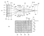
- FIG. 3A shows a case where an image is projected on the screen SC1 or a projection object arranged at a position relatively near to the projector 2, and FIG. 3B shows each display unit 21 or each The image source area AS set in the liquid crystal panel 21a is shown.
- the image source area AS of the liquid crystal panel 21a arranged in a matrix is arranged more outward in the liquid crystal panel 21a in the outer area. More specifically, the image source area AS is shifted away from the optical axis OA with reference to the standard position corresponding to the divided optical axis OA1 shown in FIG. 2 (A).
- the shift amount at this time depends on the relative arrangement of the liquid crystal panels 21a, and increases proportionally as the liquid crystal panels 21a move away from the optical axis OA.
- FIG. 3A since the image light beams IM0, IM1, IM2 intersect the optical axis OA in front of the conjugate position PC, the optical axis OA in front also after passing through the projection optical system 40.
- a post-projection focal plane FC ′ or screen SC1 set on the rear side or rear side of the projection optical system 40.
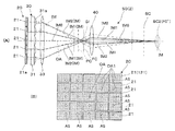
- FIG. 4A shows a case where an image is projected on the screen SC2 or a projection object arranged at a position relatively far from the projector 2, and FIG.
- FIG. 4B shows each display unit 21 or each The image source area AS set in the liquid crystal panel 21a is shown.
- the image source area AS of the liquid crystal panel 21a arranged in a matrix is arranged more inward as the liquid crystal panel 21a in the outer area. More specifically, the image source area AS is shifted toward the optical axis OA with reference to the standard position corresponding to the divided optical axis OA1 shown in FIG. 2 (A). Furthermore, the shift amount at this time increases proportionately as the liquid crystal panel 21a moves away from the optical axis OA. As a result, as shown in FIG.
- the image light beams IM0, IM1, IM2 intersect the optical axis OA behind the conjugate position PC, and therefore the optical axis OA also after passing through the projection optical system 40. Intersect, which becomes the post-projection focal plane FC 'or the screen SC2.
- FC post-projection focal plane
- the formation position of this small image G1 corresponds to the superposition position of the image rays IM0, IM1, IM2, and is a projection front focal plane FC.
- the two-dimensional arrangement pattern of the image source area AS set in the plurality of liquid crystal panels 21a arranged in a matrix is Based on the lattice point arrangement corresponding to the standard position shown in FIG. 2B, the lattice points are similarly expanded or reduced while keeping the centers through which the optical axis OA passes coincident.
- FIG. 5A and 5B are a front view and a side view showing an example of a projection object
- FIG. 5C illustrates a specific example of the image source area AS set in the liquid crystal panel 21a. It is a figure to do.
- the projection object PO shown to FIG. 5 (A) and 5 (B) is hemispherical shape, and the center protrudes in the projector 2 side.
- the case where the surface of the projection object PO is divided into the areas AR11, AR12, AR13, and AR14 by contour lines based on the distance from the projector 2 will be described. Images are projected at once as equidistant to each of the areas AR11 to AR14.
- the display unit 121 shown in FIG. 5C corresponds to the display unit 21 in the upper right corner of the display unit 21 shown in FIG. 2A. Focusing on the display unit 121, the image projected on the closest area AR11 in FIG. 5A is a circular image corresponding to the outline of the area AR11 in the image source area AS11 relatively close to the divided optical axis OA1. It is formed in the image range G11. In FIG. 5A, an image projected to a relatively short distance area AR12 is formed in a ring-shaped image range G12 corresponding to the outline of the area AR12 in an image source area AS12 next closest to the divided optical axis OA1 . In FIG.
- the image projected on the relatively long distance area AR13 is formed in a ring-shaped image range G13 corresponding to the outline of the area AR13 in the image source area AS13 far from the divided optical axis OA1.
- the image projected on the farthest area AR14 in FIG. 5A is formed in a ring-shaped image area G14 corresponding to the outline of the area AR14 in the image source area AS14 relatively far from the divided optical axis OA1.
- the images displayed in the image source areas AS11 to AS14 can be corrected in consideration of the inclination and the curvature of the respective areas AR11 to AR14.
- the distance D corresponds to the focus movement amount of an intermediate image (corresponding to the small image G1 shown in FIG. 1) formed in front of the projection optical system 40. That is, by adjusting the amount of focus movement of the intermediate image before and after the conjugate position PC, the focus position of the projection image by the projection optical system 40 can be adjusted before and after the basic position. Specifically, the imaging position can be moved from the specific point (projected position) IP0 on the screen SC to the first point (projected position) IP1.
- the conditions for forming an image (central image) at the intersection IP3 of The intersection point IP3 is a conjugate point of the first point IP1 shown in FIG. 6A with respect to the projection optical system 40.
- E be a distance between the superposing lens 33 and the conjugate position PC, and consider an image ray IM emitted from the specific liquid crystal panel 21a of the display device 20 toward the intersection IP3.
- the emission position of the image light beam IM deviates from the standard position on the split optical axis OA1 and moves away from the optical axis OA.
- G be a displacement amount at which the emission position of the image light beam IM at this time deviates from the optical axis OA as a whole reference. How much the emission position of the image beam IM is shifted in the liquid crystal panel 21a in accordance with the change of the focus position or the superposing position corresponds to how much the image beam IM deviates from the optical axis OA at the conjugate position PC.
- FIG. 7B conditions for forming an image (peripheral image) at an off-axis point IP4 shifted from the intersection point IP3 in a direction perpendicular to the optical axis OA will be described.
- This off-axis point IP4 corresponds to the second point IP2 in FIG. 6 (A).
- the amount by which the image light beam IM deviates from the optical axis OA at the conjugate position PC is the sum of the distance I from the optical axis OA of the off-axis point IP4 and the amount of deviation H 'due to the angle of the image light IM. It has become.
- the shift amount H 'at the conjugate position PC corresponding to the shift amount H0' for shifting the emission position of the image beam IM from the original position in the liquid crystal panel 21a is the optical axis of the emission position from the optical axis OA of the image beam IM.
- G 'be the amount of deviation from OA, and J be the additional portion due to being a peripheral image
- the shift amount H ′ corresponding to the off-axis point IP4 shifted from the optical axis OA at the conjugate position PC is slightly different compared to the shift amount H corresponding to the intersection IP3 on the optical axis OA
- the deviation amount H0 and the deviation amount H0 ' are also slightly different.
- the image to be displayed in the image source area AS of each liquid crystal panel 21a is one in which the basic image is deformed or distorted in anticipation of deformation according to the focus position (superimposed position). Furthermore, the image displayed on the image source area AS of each liquid crystal panel 21a is also subjected to modification, shift or the like depending on the degree to which the liquid crystal panel 21a deviates from the optical axis OA.
- the circuit device 80 drives the display processing unit 81 provided in the optical system portion 50 based on the output of the image processing unit 81 to which image data is input from the outside and the image processing unit 81.
- a main control unit 88 that generally controls the operations of the image processing unit 81 and the display driving unit 82.
- the image processing unit 81 and the main control unit 88 function as a display control unit 80 a that controls the operation of the display device 20.
- the image processing unit 81 forms an image signal for operating each liquid crystal panel 21a constituting the display device 20 based on image data from the outside.
- the image data from the outside can include, for example, image content for each projection distance from the projector 2.
- the image information to be projected to the area (distance zone) at a plurality of stepwise projection distances from the projector 2 is read out to each liquid crystal panel 21a.
- the image processing unit 81 calculates an image to be displayed for each image source area AS of each liquid crystal panel 21 a, so that the image source area of each liquid crystal panel 21 a from the projector 2 with respect to the target projection distance area. It is possible to superimpose the image formed on AS without deviation and to project a bright and sharp image. As described above, no congruent image is formed in each of the image source areas AS. For example, according to the degree of positional deviation of the liquid crystal panel 21a from the center of the display device 20 through which the optical axis OA passes, and the change in focus position. It is assumed that the image has been deformed. The image processing unit 81 performs deformation or correction processing of an image according to the change of the position of the liquid crystal panel 21a or the focus position.
- the display driving unit 82 can operate the liquid crystal panel 21a that configures the display device 20 based on the image signal output from the image processing unit 81, and can form a corresponding image on the liquid crystal panel 21a.
- distance image data is externally fetched under the control of the main control unit 88 (step S11).
- the distance image data is image data including three-dimensional information, and includes distance zone information and image information.
- the distance zone information is information on which distance zone among the plurality of distance zones corresponding to the division of the projection distance from the projector 2 stepwise into the range of the plurality of sections, and the image information is the distance It contains image data to be displayed for each zone.
- the distance zone is similar to the area between a pair of adjacent contour lines, and the image data sets an image to be displayed in the region between a pair of adjacent contour lines for each distance zone (For a specific example, refer to image source areas AS11 to AS14, image ranges G11 to G14, and the like in FIG. 5C). That is, image data to be projected on a plurality of focus positions represented by the distance zone is prepared in advance.
- the main control unit 88 sets a projection distance zone from the distance image data (step S12). That is, the distance zone to be the target of the current projection is selected from the plurality of distance zones, and this is set as the projection distance zone.
- the main control unit 88 selects image information or image data corresponding to the projection distance zone obtained in step S12 as a display target (step S13).
- an image source area AS (see FIG. 2A, FIG. 3B, FIG. 4B, etc.) to display an image in each liquid crystal panel 21a is set (step S14).
- the image source area AS is calculated by the image processing unit 81 and the like from the projection distance zone obtained in step S12.
- the image processing unit 81 performs a correction process on the image data selected in step S13 for each of the image source areas AS calculated in step S14 (step S15). This is because, as described in FIGS.
- the image ray IM is corrected by correcting the image to be formed in the image source area AS according to the degree to which the liquid crystal panel 21a is separated from the optical axis OA. Is accurate and the small image G1 can be sharpened.
- the image processing unit 81 outputs the image signal after the correction process to the display driving unit 82 (step S16).
- the display driving unit 82 drives the liquid crystal panels 21 a that constitute the display device 20 to cause the liquid crystal panels 21 a to perform display corresponding to the image signal input from the image processing unit 81.
- the main control unit 88 determines whether the distance zone to be the target of the next projection remains among the plurality of distance zones obtained in step S11 (step S17).
- step S18 If a distance zone to be subjected to the next projection remains, the process returns to step S12 to select a distance zone to be subjected to the current projection after updating. If no distance zone remains in step S17, it is determined whether there is a next frame (step S18). The absence of the distance zone means that the projection of one image has been completed. That is, by repeating steps S12 to S17, an image is projected in a time division manner to all projection distance zones which are three-dimensional ranges. On the other hand, if it is determined in step S18 that the next frame is present, the process returns to step S11, and the distance image data corresponding to the next frame is fetched. When the frame changes in time series, if the speed of change is fast, the moving image is displayed on the image source area AS, and a three-dimensional moving image is projected on the surface of the three-dimensional projection object It will be.
- the distance and orientation from the projector 2 to the projection object are known and the shape of the projection object is also known, but the distance and orientation to the projection object are unknown Even the same projection is possible.
- the same projection operation as that in FIG. 8 is possible.
- the same projection can be performed by measuring the shape of the projection object.
- the distance image data is partially prepared or processed in the projector 2.
- the projection optical system 40 projects the image superimposed by the superposition optical system 30, and the position at which the display control unit 80a superimposes the image light beam IM with respect to the optical axis OA direction Since different superimposed positions are set, projection can be performed simultaneously and in parallel to different depth spaces.
- the projector of the second embodiment will be described below.
- the projector of the second embodiment is a modification of the projector of the first embodiment, and portions that are not particularly described have the same structure as the projector of the first embodiment.
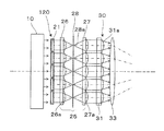
- a parallel light selection unit (light beam selection unit) 25 is provided in the display device 120.
- the parallel light selection unit 25 has a structure similar to that of the lens array 31 of the superposition optical system 30 and is aligned between the lens arrays 26 and 26 and a pair of lens arrays 26 and 27 arranged concentrically. And an array of pinholes 28.
- the image light beam emitted from each display unit 21 is converged through the lens element 26a of the lens array 26, passes through the pinhole 28a on the split optical axis of the pinhole array 28, and passes through the lens element 27a of the lens array 27. It enters the lens element 31 a of the lens array 31 in a collimated or collimated state.
- the light source used as the illumination unit 10 is not limited to a surface emitting laser, and may be a lamp, a mirror, a collimator lens, or the like.
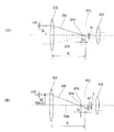
- the projector of the third embodiment will be described below.
- the projector of the third embodiment is a modification of the projector of the first embodiment, and parts that are not particularly described have the same structure as the projector of the first embodiment.
- the projector 2 includes, as an optical system portion 50, image forming units 51R, 51G, and 51B for red, green, and blue, a cross dichroic prism 55, and a projection optical system 40. Equipped with
- the image forming units 51R, 51G, and 51B for the respective colors have the same functions as the illumination unit 10, the display device 20, and the superposing optical system 30 shown in FIG. 1, but the illumination unit 10 and the display device 20 have different display colors. And the superposition optical system 30 respectively.
- the cross dichroic prism 55 is a prism for light synthesis, and combines the image light rays formed by the respective image forming units 51R, 51G, and 51B into image light and causes the light to be incident on the projection optical system 40.
- the projection optical system 40 can magnify and project the image light modulated by the image forming units 51R, 51G, and 51B and combined by the cross dichroic prism 55 on a three-dimensional target (not shown).
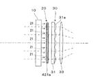
- the display device 20 can be configured by a single liquid crystal panel 421a.
- a large number of two-dimensionally arranged display portions 21 are provided in the liquid crystal panel 421a.
- the outline and the arrangement method of the display part 21 in the display apparatus 20 can be made various not only in what arranges the area
- the arrangement of the display unit 21 can be a pattern arranged on various lattice points such as a triangular lattice or a hexagonal lattice, for example, and the outline of the display unit 21 can be polygonal, circular or the like.
- the arrangement of the superposing lens 21 b corresponds to the arrangement of the display unit 21.
- the arrangement of the display unit 21 does not have to be dense, and can be arranged at any two-dimensional point. Also in this case, the arrangement of the superposing lens 21 b corresponds to the arrangement of the display unit 21.
- the display unit 21 constituting the display device 20 can be said to be capable of projection by superimposing it if it is two or more, but from the viewpoint of projecting a bright image, it may be a 5 ⁇ 5 or more matrix array or the like desirable.
- the display element provided in the display device 20 is not limited to the transmissive liquid crystal panel 21a, but may be a reflective liquid crystal panel. In this case, two-dimensional alignment of the reflective liquid crystal panels is also possible by collectively illuminating one row of reflective liquid crystal panels and arranging the plurality of reflective liquid crystal panels illuminated for each row. Furthermore, as a display element provided in the display device 20, various light modulation elements such as a digital micro mirror device having a micro mirror as a pixel can also be used.
- the projection optical system 40 may be a zoom lens, can be reduced and projected, and can have a variable depth of field. By adjusting the depth of field of the projection optical system 40, the display range in the depth direction can be expanded. Furthermore, by making the focus state of the projection optical system 40 variable, it is possible to move the three-dimensional projection space by the projector 2 along the direction of the optical axis OA.
- Pinhole array 30: superposition optical system, 31: lens array, 31a: lens element, 33: superposition lens, 40: projection optical system, 50: optical system part, 51R, 51G, 51B: image forming part, 55: cross Dichroic prism, 80: circuit device, 80a: display control unit, 81: image processing unit, 82: display drive unit, 88: main control unit, AR11-AR14: area, AS: image source area, AS11-AS14: image source Area, FC '... projection back focal plane, FC ... projection front focal plane, G1 ... pictogram, G11-G14 ... image range Image beam, IM0, IM1, IM2 Image beam, IP0 ... Specific point, IP3 ... Intersection, IP4 ... Off-axis point, LI ... Illumination light, OA ... Optical axis, OA1 ... Split optical axis, PC ... Conjugate Position, PO ... Projected object.
Landscapes
- Physics & Mathematics (AREA)
- General Physics & Mathematics (AREA)
- Engineering & Computer Science (AREA)
- Multimedia (AREA)
- Signal Processing (AREA)
- Optics & Photonics (AREA)
- Projection Apparatus (AREA)
- Transforming Electric Information Into Light Information (AREA)
- Liquid Crystal (AREA)
Abstract
Description
図1に示すように、本発明に係る第1実施形態のプロジェクター2は、画像光を投射する光学系部分50と、光学系部分50の動作を制御する回路装置80とを備える。
図4(A)は、プロジェクター2に対して比較的遠い位置に配置されたスクリーンSC2又は被投射体に画像を投射する場合を示しており、図4(B)は、各表示部21又は各液晶パネル21aに設定する像源領域ASを示している。図4(B)に示すように、遠距離投射の場合、マトリックス状に配列された液晶パネル21aの像源領域ASは、外側の領域にある液晶パネル21aのものほど内側に配置されている。より具体的には、像源領域ASは、図2(A)に示す分割光軸OA1に対応する標準位置を基準として光軸OAに近づく方にシフトさせたものとなっている。さらに、この際のシフト量は、液晶パネル21aが光軸OAから離れるほど比例的に大きくなる。この結果、図4(A)に示すように、像光線IM0,IM1,IM2は、共役位置PCより後方で光軸OAと交差するため、投射光学系40を通過した後も後方で光軸OAと交差し、ここが投射後焦点面FC'又はスクリーンSC2となる。
以上のように、各液晶パネル21aに設定される像源領域ASの配置を調整することで、光の強度分布を有する像光線IMを形成できるだけでなく、像光線IMの射出角度を制御できる。これにより、共役位置PCを中心として光軸OA方向の前後の所望位置に所望の輝度及び色彩分布を有する小像G1を形成できる。この小像G1の形成位置は、像光線IM0,IM1,IM2の重畳位置に相当し、投射前焦点面FCとなっている。投射前焦点面(重畳位置)FCの位置を共役位置PCの前後に変化させる際に、マトリックス状に配列された複数の液晶パネル21aにおいて設定される像源領域ASの2次元的配置パターンは、図2(B)に示す標準位置に対応する格子点状の配列を基準として、光軸OAが通る中心を一致させたままで相似的に拡大又は縮小された格子点状のものとなる。
以上は、右上隅の表示部121における表示動作について説明したが、他の表示部21でも、像源領域AS11~AS14の液晶パネル21a内での位置が異なるが表示部121と類似する表示が行われる。ただし、画像範囲G11~G14の輪郭や表示画像は、表示部21ごとに若干異なるものとなる。
1/C+1/B=1/F_pj
の関係が成り立つ。
図6(C)に概念的に示すように、表示装置20自体によってフォーカスをスクリーンSCより距離Aだけ手前に移動させる場合、スクリーンSCと投射光学系40との距離をB'とし、投射光学系40と第1点IP1に対応する交差点IP3との距離をC'とすると、レンズの一般式から
1/C'+1/B'=1/F_pj
の関係が成り立つ。つまり、スクリーン位置から距離Aだけ手前にフォーカスを移動させたい場合、
1/(C+D)+1/(B-A)=1/F_pj
となり、投射光学系40の焦点距離F_pj、距離A等から、共役位置PCから目的とする投射前焦点面FC又は交差点IP3までの距離Dを求めることができる。距離Dは、投射光学系40の手前に形成される中間像(図1に示す小像G1に相当)のフォーカス移動量に対応する。つまり、この中間像のフォーカス移動量を共役位置PCの前後で変化させる調整を行うことで、投射光学系40による投射像のフォーカス位置を基本位置の前後で調整することができる。具体的には、結像位置をスクリーンSC上の特定点(被投写位置)IP0から第1点(被投写位置)IP1に移動させることができる。
H:D=G:(E-D)
H=D×G/(E-D) … (1)
と求まる。つまり、交差点IP3の像(中心像)については、像光線IMの射出位置の光軸OAから距離Gに比例してズレ量H又はズレ量H0が大きくなる。
次に、図7(B)を参照して、交差点IP3から光軸OAに垂直な方向にずれた軸外点IP4に像(周辺像)を形成する条件について説明する。この軸外点IP4は、図6(A)の第2点IP2に対応する。この際、共役位置PCで像光線IMが光軸OAからずれる量は、軸外点IP4の光軸OAからの距離Iと、像光線IMの角度に起因するズレ量H'とを加算したものとなっている。ただし、軸外点IP4に着目した場合、液晶パネル21aにおいて像光線IMの射出位置をフォーカス位置又は重畳位置の変更前の元の位置からどの程度ずらすかは、ズレ量H'だけを考えればよい。したがって、液晶パネル21aにおいて像光線IMの射出位置を元の位置からシフトさせるズレ量H0'に相当する共役位置PCでのズレ量H'は、像光線IMの光軸OAから射出位置の光軸OAからのズレ量をG'とし、周辺像であることに起因する追加分をJとして、
E-D:G'+I=D:H'
H'=D×(G'+I)/(E-D) … (2)
=D×(G+I+J)/(E-D) … (3)
となる。つまり、共役位置PCにおいて光軸OAからずれた軸外点IP4に対応するズレ量H'は、光軸OA上の交差点IP3に対応するズレ量Hと比較して僅かに異なるものとなっており、ズレ量H0及びズレ量H0'も、僅かに異なるものとなる。
なお、実際の装置では、シミュレーションによって像光線IMの振る舞いを予め確認するので、上記のような計算を必ずしも必要とせず、フォーカス位置の変更前後で液晶パネル21aの像源領域ASに表示させる画像の変形量やシフト量を変換データテーブルとして保管しておけば、簡単な画像変換処理によってフォーカス位置に応じた歪みのないシャープな画像を対象又は被投射体に投射することができる。
次に、主制御部88は、距離画像データから投射距離ゾーンを設定する(ステップS12)。つまり、上記複数の距離ゾーンのうち今回の投射の対象となる距離ゾーンを選択し、これを投射距離ゾーンとする。
次に、主制御部88は、ステップS12で得た投射距離ゾーンに対応する画像情報又は画像データを表示対象として選択する(ステップS13)。
次に、各液晶パネル21aにおいて画像を表示すべき像源領域AS(図2(A)、図3(B)、図4(B)等参照)を設定する(ステップS14)。像源領域ASは、画像処理部81等により、ステップS12で得た投射距離ゾーンから計算される。
次に、ステップS14で算出した像源領域ASごとに、画像処理部81により、ステップS13で選択した画像データに対する補正処理を行う(ステップS15)。これは、図7(A)及び7(B)で説明したように、液晶パネル21aが光軸OAから離れている程度によって像源領域ASに形成すべき画像を修正することで、像光線IMの重畳が正確となって小像G1をシャープにすることができるからである。
次に、画像処理部81は、補正処理後の画像信号を表示駆動部82に出力する(ステップS16)。表示駆動部82は、表示装置20を構成する各液晶パネル21aを駆動して、画像処理部81から入力された画像信号に対応する表示を各液晶パネル21aに行わせる。
その後、主制御部88は、ステップS11で得た複数の距離ゾーンのうち次の投射の対象となる距離ゾーンが残っているか否かを判断する(ステップS17)。次の投射の対象となる距離ゾーンが残っている場合、ステップS12に戻って更新後の今回の投射の対象となる距離ゾーンを選択する。
ステップS17で距離ゾーンが残っていない場合、次のフレームが存在するか否かを判断する(ステップS18)。距離ゾーンが残っていないということは、一つの画像の投射が完了したことを意味する。つまり、ステップS12~S17を繰り返すことで、3次元的な範囲である全ての投射距離ゾーンに対して時分割で画像を投射することになる。一方、ステップS18で次のフレームが存在すると判断された場合、ステップS11に戻って次のフレームに対応する距離画像データの取り込みを行う。
なお、フレームが時系列的に変化する場合、その変化速度が速ければ、像源領域ASに動画を表示させることになり、立体的な被投射体の表面上に立体的な動画が投影されることになる。
以下に、第2実施形態のプロジェクターについて説明する。第2実施形態のプロジェクターは、第1実施形態のプロジェクターを変形したものであり、特に説明しない部分は、第1実施形態のプロジェクターと同様の構造を有する。
なお、照明部10として用いる光源は、面発光レーザーに限らず、ランプ、ミラー、コリメーターレンズ等で構成することができる。
以下に、第3実施形態のプロジェクターについて説明する。第3実施形態のプロジェクターは、第1実施形態のプロジェクターを変形したものであり、特に説明しない部分は、第1実施形態のプロジェクターと同様の構造を有する。
さらに、表示部21の配列は、稠密的である必要はなく、2次元的な任意の点に配置することもできる。この場合も、重畳レンズ21bの配列は、表示部21の配列に対応させる。
表示装置20を構成する表示部21は、2つ以上であればその重畳によって投射が可能になると言えるが、明るい画像を投射する観点では、5×5或いはそれ以上のマトリックス配列等とすることが望ましい。
さらに、表示装置20に設ける表示素子として、マイクロミラーを画素とするデジタル・マイクロミラー・デバイス等の各種光変調素子を用いることもできる。
Claims (12)
- コリメートされた像光線を形成する複数の表示部と、
前記複数の表示部から射出された像光線を集光させない状態で互いに重畳させる重畳光学系と、
前記重畳光学系によって重畳された像光線に対応する像を投射する投射光学系と、
前記複数の表示部ごとに設定された局所的な像源領域から像光線を射出させることによって、像光線を重畳させる位置を光軸方向に関して異なる複数の重畳位置に設定する表示制御部とを備えるプロジェクター。 - 前記重畳光学系は、前記複数の表示部にそれぞれ対向する複数のレンズ要素と、前記複数のレンズ要素を経た像光線が互いに集まるように像光線を重畳させる重畳レンズとを備える、請求項1に記載のプロジェクター。
- 前記像源領域の中心は、各表示部において、当該各表示部の相対的配置と前記重畳位置の設定とに応じて、基準となる標準位置からシフトさせた位置に設定される、請求項1及び2のいずれか一項に記載のプロジェクター。
- 前記各表示部において、前記像源領域の中心の前記標準位置からのシフト量は、前記重畳光学系の光軸が通る中央からの前記各表示部の中心までの距離に略比例する、請求項3に記載のプロジェクター。
- 前記複数の表示部に表示させる複数の画像は、前記中央からのズレに応じて基本画像に変形を施したものである、請求項4に記載のプロジェクター。
- 前記各表示部において前記像源領域の中心が前記標準位置にあるとき、前記重畳位置は、前記重畳光学系に関して前記各表示部の共役位置になっている、請求項3~5のいずれか一項に記載のプロジェクター。
- 前記複数の表示部は、単一の表示素子に形成された複数の部分、又は、複数の表示素子に対応する、請求項1~6のいずれか一項に記載のプロジェクター。
- 前記複数の表示部は、透過型の表示素子と、前記表示素子を照明する照明部とを有する、請求項1~7のいずれか一項に記載のプロジェクター。
- 前記照明部は、面発光レーザーを備える、請求項8に記載のプロジェクター。
- 前記複数の表示部は、一対のレンズアレイの間にピンホールアレイを挟んだ光線選択部を有し、当該光線選択部によって平行にされた像光線を選択的に通過させる、請求項1~8のいずれか一項に記載のプロジェクター。
- 前記表示制御部は、前記重畳位置を時分割で変化させて前記投射光学系による投射位置を3次元的な範囲とする、請求項1~10のいずれか一項に記載のプロジェクター。
- 前記表示制御部は、前記複数の表示部の前記像源領域において動画を表示させる、請求項1~11のいずれか一項に記載のプロジェクター。
Priority Applications (4)
| Application Number | Priority Date | Filing Date | Title |
|---|---|---|---|
| US15/122,358 US9946140B2 (en) | 2014-03-26 | 2015-03-17 | Projector capable of projection in different positions in the depth direction |
| EP15769661.8A EP3125040A4 (en) | 2014-03-26 | 2015-03-17 | Projector |
| CN201580014178.4A CN106104377A (zh) | 2014-03-26 | 2015-03-17 | 投影仪 |
| KR1020167028673A KR20160132991A (ko) | 2014-03-26 | 2015-03-17 | 프로젝터 |
Applications Claiming Priority (2)
| Application Number | Priority Date | Filing Date | Title |
|---|---|---|---|
| JP2014-063249 | 2014-03-26 | ||
| JP2014063249A JP6277816B2 (ja) | 2014-03-26 | 2014-03-26 | プロジェクター |
Publications (1)
| Publication Number | Publication Date |
|---|---|
| WO2015146073A1 true WO2015146073A1 (ja) | 2015-10-01 |
Family
ID=54194624
Family Applications (1)
| Application Number | Title | Priority Date | Filing Date |
|---|---|---|---|
| PCT/JP2015/001484 Ceased WO2015146073A1 (ja) | 2014-03-26 | 2015-03-17 | プロジェクター |
Country Status (7)
| Country | Link |
|---|---|
| US (1) | US9946140B2 (ja) |
| EP (1) | EP3125040A4 (ja) |
| JP (1) | JP6277816B2 (ja) |
| KR (1) | KR20160132991A (ja) |
| CN (1) | CN106104377A (ja) |
| TW (1) | TWI644158B (ja) |
| WO (1) | WO2015146073A1 (ja) |
Families Citing this family (4)
| Publication number | Priority date | Publication date | Assignee | Title |
|---|---|---|---|---|
| CN106990663A (zh) * | 2017-06-05 | 2017-07-28 | 电子科技大学中山学院 | 一种便携式可折叠三维户型投影装置 |
| JP7202906B2 (ja) | 2019-01-25 | 2023-01-12 | 株式会社ワコム | ペンが送信したペン信号を検出するためのセンサパネル |
| JP7223287B2 (ja) * | 2020-09-17 | 2023-02-16 | カシオ計算機株式会社 | 光源装置、投影装置、及び光源制御方法 |
| CN114842779B (zh) * | 2022-05-26 | 2026-02-17 | 青岛海信激光显示股份有限公司 | 激光投影图像显示方法、设备和计算机存储介质 |
Citations (5)
| Publication number | Priority date | Publication date | Assignee | Title |
|---|---|---|---|---|
| JP2012003232A (ja) * | 2010-06-15 | 2012-01-05 | Fraunhofer Ges Zur Foerderung Der Angewandten Forschung Ev | 投射型ディスプレイおよび全体像を表示する方法 |
| WO2012156280A1 (de) * | 2011-05-18 | 2012-11-22 | Fraunhofer-Gesellschaft zur Förderung der angewandten Forschung e.V. | Projektionsdisplay und verfahren zum anzeigen eines gesamtbilds für projektionsfreiformflächen oder verkippte projektionsflächen |
| JP2012530263A (ja) * | 2009-06-15 | 2012-11-29 | フラウンホッファー−ゲゼルシャフト ツァー フェーデルング デア アンゲバンテン フォルシュング エー ファー | 投射型表示装置及びその利用 |
| JP2013521529A (ja) * | 2010-03-04 | 2013-06-10 | トビス カンパニー リミテッド | 多層映像表示装置 |
| WO2013118328A1 (ja) * | 2012-02-07 | 2013-08-15 | オリンパス株式会社 | 表示装置、電子機器及び表示装置用プログラム |
Family Cites Families (9)
| Publication number | Priority date | Publication date | Assignee | Title |
|---|---|---|---|---|
| US6545653B1 (en) * | 1994-07-14 | 2003-04-08 | Matsushita Electric Industrial Co., Ltd. | Method and device for displaying image signals and viewfinder |
| TW561296B (en) | 1996-10-30 | 2003-11-11 | Seiko Epson Corp | Projection display and its illuminating optical system |
| TW434444B (en) | 1996-10-30 | 2001-05-16 | Seiko Epson Corp | Projection display and illuminating optical system for it |
| JP4013907B2 (ja) | 2004-03-08 | 2007-11-28 | セイコーエプソン株式会社 | プロジェクタ |
| KR101134208B1 (ko) | 2004-10-01 | 2012-04-09 | 더 보드 어브 트러스티스 어브 더 리랜드 스탠포드 주니어 유니버시티 | 촬상 장치 및 그 방법 |
| GB2461294B (en) * | 2008-06-26 | 2011-04-06 | Light Blue Optics Ltd | Holographic image display systems |
| KR101700186B1 (ko) | 2009-09-14 | 2017-02-13 | 엘지전자 주식회사 | 레이저 프로젝터 디스플레이 |
| JP5924042B2 (ja) * | 2012-03-14 | 2016-05-25 | セイコーエプソン株式会社 | プロジェクター、及び、プロジェクターの制御方法 |
| DE102012205164B4 (de) | 2012-03-29 | 2021-09-09 | Fraunhofer-Gesellschaft zur Förderung der angewandten Forschung e.V. | Projektionsdisplay und Verfahren zur Projektion virtueller Bilder |
-
2014
- 2014-03-26 JP JP2014063249A patent/JP6277816B2/ja not_active Expired - Fee Related
-
2015
- 2015-03-17 EP EP15769661.8A patent/EP3125040A4/en not_active Withdrawn
- 2015-03-17 US US15/122,358 patent/US9946140B2/en active Active
- 2015-03-17 KR KR1020167028673A patent/KR20160132991A/ko not_active Ceased
- 2015-03-17 CN CN201580014178.4A patent/CN106104377A/zh active Pending
- 2015-03-17 WO PCT/JP2015/001484 patent/WO2015146073A1/ja not_active Ceased
- 2015-03-23 TW TW104109225A patent/TWI644158B/zh active
Patent Citations (5)
| Publication number | Priority date | Publication date | Assignee | Title |
|---|---|---|---|---|
| JP2012530263A (ja) * | 2009-06-15 | 2012-11-29 | フラウンホッファー−ゲゼルシャフト ツァー フェーデルング デア アンゲバンテン フォルシュング エー ファー | 投射型表示装置及びその利用 |
| JP2013521529A (ja) * | 2010-03-04 | 2013-06-10 | トビス カンパニー リミテッド | 多層映像表示装置 |
| JP2012003232A (ja) * | 2010-06-15 | 2012-01-05 | Fraunhofer Ges Zur Foerderung Der Angewandten Forschung Ev | 投射型ディスプレイおよび全体像を表示する方法 |
| WO2012156280A1 (de) * | 2011-05-18 | 2012-11-22 | Fraunhofer-Gesellschaft zur Förderung der angewandten Forschung e.V. | Projektionsdisplay und verfahren zum anzeigen eines gesamtbilds für projektionsfreiformflächen oder verkippte projektionsflächen |
| WO2013118328A1 (ja) * | 2012-02-07 | 2013-08-15 | オリンパス株式会社 | 表示装置、電子機器及び表示装置用プログラム |
Non-Patent Citations (1)
| Title |
|---|
| See also references of EP3125040A4 * |
Also Published As
| Publication number | Publication date |
|---|---|
| KR20160132991A (ko) | 2016-11-21 |
| US9946140B2 (en) | 2018-04-17 |
| EP3125040A4 (en) | 2017-11-15 |
| TWI644158B (zh) | 2018-12-11 |
| CN106104377A (zh) | 2016-11-09 |
| JP2015184619A (ja) | 2015-10-22 |
| TW201539104A (zh) | 2015-10-16 |
| JP6277816B2 (ja) | 2018-02-14 |
| US20160373702A1 (en) | 2016-12-22 |
| EP3125040A1 (en) | 2017-02-01 |
Similar Documents
| Publication | Publication Date | Title |
|---|---|---|
| US9247222B2 (en) | Projection display and method for displaying an overall image for projection free-form surfaces or tilted projection surfaces | |
| JP5719650B2 (ja) | 投射型ディスプレイおよび全体像を表示する方法 | |
| KR20040011761A (ko) | 화소이동수단을 구비하는 고해상도 디스플레이 | |
| JP6202806B2 (ja) | 虚像表示装置 | |
| WO2015146072A1 (ja) | プロジェクター | |
| CN105319823B (zh) | 投影仪以及投影仪的调整方法 | |
| JP6277816B2 (ja) | プロジェクター | |
| JP6854908B2 (ja) | 光学系、投影装置及び撮像装置 | |
| JP4405525B2 (ja) | 三次元光線取得装置 | |
| JP2016176996A (ja) | 画像投影装置 | |
| JP6899237B2 (ja) | 立体映像表示装置 | |
| JP2009192561A (ja) | 画像表示装置 | |
| JP2015184619A5 (ja) | ||
| JP4736350B2 (ja) | プロジェクタおよび表示装置 | |
| JP2002372677A (ja) | 投影型画像表示装置及びその合波光学系 | |
| JP2010256674A (ja) | 投射型表示装置 | |
| JP5032796B2 (ja) | 立体画像表示装置 | |
| KR100832620B1 (ko) | 단판식 회절형 광변조기를 이용한 디스플레이 장치 | |
| JP7726099B2 (ja) | プロジェクター | |
| EP1962516B1 (en) | Projection optical system | |
| JP2000347131A (ja) | 照明光学装置および投射型表示装置 | |
| JP2000206617A (ja) | 照明装置及び投写型表示装置 | |
| JP2016038426A (ja) | プロジェクター | |
| JP2008170480A (ja) | 光源装置の製造装置、光源装置の製造方法、及びプロジェクタの製造方法 | |
| JP2000056393A (ja) | 表示装置、表示素子及びマイクロレンズアレイ |
Legal Events
| Date | Code | Title | Description |
|---|---|---|---|
| 121 | Ep: the epo has been informed by wipo that ep was designated in this application |
Ref document number: 15769661 Country of ref document: EP Kind code of ref document: A1 |
|
| WWE | Wipo information: entry into national phase |
Ref document number: 15122358 Country of ref document: US |
|
| NENP | Non-entry into the national phase |
Ref country code: DE |
|
| REEP | Request for entry into the european phase |
Ref document number: 2015769661 Country of ref document: EP |
|
| WWE | Wipo information: entry into national phase |
Ref document number: 2015769661 Country of ref document: EP |
|
| ENP | Entry into the national phase |
Ref document number: 20167028673 Country of ref document: KR Kind code of ref document: A |