WO2015146290A1 - 内視鏡用撮像ユニット - Google Patents
内視鏡用撮像ユニット Download PDFInfo
- Publication number
- WO2015146290A1 WO2015146290A1 PCT/JP2015/052962 JP2015052962W WO2015146290A1 WO 2015146290 A1 WO2015146290 A1 WO 2015146290A1 JP 2015052962 W JP2015052962 W JP 2015052962W WO 2015146290 A1 WO2015146290 A1 WO 2015146290A1
- Authority
- WO
- WIPO (PCT)
- Prior art keywords
- frame
- objective lens
- fitting portion
- holding frame
- image sensor
- Prior art date
- Legal status (The legal status is an assumption and is not a legal conclusion. Google has not performed a legal analysis and makes no representation as to the accuracy of the status listed.)
- Ceased
Links
Images




Classifications
-
- A—HUMAN NECESSITIES
- A61—MEDICAL OR VETERINARY SCIENCE; HYGIENE
- A61B—DIAGNOSIS; SURGERY; IDENTIFICATION
- A61B1/00—Instruments for performing medical examinations of the interior of cavities or tubes of the body by visual or photographical inspection, e.g. endoscopes; Illuminating arrangements therefor
- A61B1/00163—Optical arrangements
-
- A—HUMAN NECESSITIES
- A61—MEDICAL OR VETERINARY SCIENCE; HYGIENE
- A61B—DIAGNOSIS; SURGERY; IDENTIFICATION
- A61B1/00—Instruments for performing medical examinations of the interior of cavities or tubes of the body by visual or photographical inspection, e.g. endoscopes; Illuminating arrangements therefor
- A61B1/00064—Constructional details of the endoscope body
- A61B1/00071—Insertion part of the endoscope body
- A61B1/0008—Insertion part of the endoscope body characterised by distal tip features
-
- A—HUMAN NECESSITIES
- A61—MEDICAL OR VETERINARY SCIENCE; HYGIENE
- A61B—DIAGNOSIS; SURGERY; IDENTIFICATION
- A61B1/00—Instruments for performing medical examinations of the interior of cavities or tubes of the body by visual or photographical inspection, e.g. endoscopes; Illuminating arrangements therefor
- A61B1/00064—Constructional details of the endoscope body
- A61B1/00071—Insertion part of the endoscope body
- A61B1/0008—Insertion part of the endoscope body characterised by distal tip features
- A61B1/00096—Optical elements
-
- A—HUMAN NECESSITIES
- A61—MEDICAL OR VETERINARY SCIENCE; HYGIENE
- A61B—DIAGNOSIS; SURGERY; IDENTIFICATION
- A61B1/00—Instruments for performing medical examinations of the interior of cavities or tubes of the body by visual or photographical inspection, e.g. endoscopes; Illuminating arrangements therefor
- A61B1/00064—Constructional details of the endoscope body
- A61B1/0011—Manufacturing of endoscope parts
-
- A—HUMAN NECESSITIES
- A61—MEDICAL OR VETERINARY SCIENCE; HYGIENE
- A61B—DIAGNOSIS; SURGERY; IDENTIFICATION
- A61B1/00—Instruments for performing medical examinations of the interior of cavities or tubes of the body by visual or photographical inspection, e.g. endoscopes; Illuminating arrangements therefor
- A61B1/04—Instruments for performing medical examinations of the interior of cavities or tubes of the body by visual or photographical inspection, e.g. endoscopes; Illuminating arrangements therefor combined with photographic or television appliances
- A61B1/044—Instruments for performing medical examinations of the interior of cavities or tubes of the body by visual or photographical inspection, e.g. endoscopes; Illuminating arrangements therefor combined with photographic or television appliances for absorption imaging
-
- A—HUMAN NECESSITIES
- A61—MEDICAL OR VETERINARY SCIENCE; HYGIENE
- A61B—DIAGNOSIS; SURGERY; IDENTIFICATION
- A61B1/00—Instruments for performing medical examinations of the interior of cavities or tubes of the body by visual or photographical inspection, e.g. endoscopes; Illuminating arrangements therefor
- A61B1/04—Instruments for performing medical examinations of the interior of cavities or tubes of the body by visual or photographical inspection, e.g. endoscopes; Illuminating arrangements therefor combined with photographic or television appliances
- A61B1/046—Instruments for performing medical examinations of the interior of cavities or tubes of the body by visual or photographical inspection, e.g. endoscopes; Illuminating arrangements therefor combined with photographic or television appliances for infrared imaging
-
- G—PHYSICS
- G02—OPTICS
- G02B—OPTICAL ELEMENTS, SYSTEMS OR APPARATUS
- G02B23/00—Telescopes, e.g. binoculars; Periscopes; Instruments for viewing the inside of hollow bodies; Viewfinders; Optical aiming or sighting devices
- G02B23/24—Instruments or systems for viewing the inside of hollow bodies, e.g. fibrescopes
- G02B23/2407—Optical details
- G02B23/2423—Optical details of the distal end
- G02B23/243—Objectives for endoscopes
-
- G—PHYSICS
- G02—OPTICS
- G02B—OPTICAL ELEMENTS, SYSTEMS OR APPARATUS
- G02B23/00—Telescopes, e.g. binoculars; Periscopes; Instruments for viewing the inside of hollow bodies; Viewfinders; Optical aiming or sighting devices
- G02B23/24—Instruments or systems for viewing the inside of hollow bodies, e.g. fibrescopes
- G02B23/2476—Non-optical details, e.g. housings, mountings, supports
- G02B23/2484—Arrangements in relation to a camera or imaging device
-
- A—HUMAN NECESSITIES
- A61—MEDICAL OR VETERINARY SCIENCE; HYGIENE
- A61B—DIAGNOSIS; SURGERY; IDENTIFICATION
- A61B1/00—Instruments for performing medical examinations of the interior of cavities or tubes of the body by visual or photographical inspection, e.g. endoscopes; Illuminating arrangements therefor
- A61B1/00064—Constructional details of the endoscope body
- A61B1/00071—Insertion part of the endoscope body
- A61B1/00075—Insertion part of the endoscope body with externally roughened shaft
Definitions
- the present invention relates to an imaging unit applied to an endoscope.
- an endoscope imaging unit has a structure in which an objective lens unit frame that holds an objective lens and an imaging element holding frame that holds an imaging element are fitted and fixed. It has become. More specifically, the objective lens unit frame and the image sensor holding frame are filled with a thermosetting resin in the fitting portion, and the optical axis direction between the objective optical system and the image sensor so that the desired focus is achieved. In a state where the positioning is performed, both are put into a drying furnace or the like while being fixed by an assembly jig and heated. Thereby, the thermosetting resin is cured, and the objective lens unit frame and the image sensor holding frame are bonded and fixed.
- thermosetting resin when the thermosetting resin is cured, the objective lens unit frame and the imaging element holding frame are heated in a drying furnace while being fixed by an assembly jig. Therefore, parts and jigs are thermally expanded. Due to this thermal expansion, the objective lens unit frame and the image sensor holding frame may be displaced from a desired position, resulting in a manufacturing error exceeding the allowable amount.
- the present invention has been made in view of the above-described circumstances, and an object thereof is to suppress manufacturing errors and improve the positioning accuracy between an imaging element and an objective lens.
- a first aspect of the present invention includes an objective lens unit frame that holds an objective lens, and an imaging element holding frame that fits into the objective lens unit frame and holds an imaging element, and the objective lens unit frame includes:
- the imaging element holding frame is fixed by being bonded and fixed by a thermosetting resin applied to these fitting portions, and is located outside when the objective lens unit frame and the imaging element holding frame are fitted.
- An endoscope imaging unit in which an outer surface of the fitting portion and an outer surface other than the fitting portion among the outer surfaces of the frame satisfy the following conditional expression is provided.
- (alpha) is the infrared absorption factor per unit area of the outer surface of the said fitting part
- (beta) is the infrared absorption factor per unit area of outer surfaces other than the said fitting part.
- the outer surface of the frame located outside when the objective lens unit frame and the imaging element holding frame are fitted to each other than the outer surface of the fitting portion and the fitting portion.
- the infrared absorption rate is higher in the fitting portion between the objective lens unit frame and the image sensor holding frame than in the portion other than the fitting portion. ing. That is, the fitting portion between the objective lens unit frame and the image sensor holding frame is configured to be easily heated by infrared irradiation as compared with the portion other than the fitting portion.
- thermosetting resin to the fitting part between the objective lens unit frame and the image sensor holding frame, positioning the two parts and fixing them with a jig, and then irradiating the fitting part with infrared rays Only the fitting portion can be efficiently heated.
- thermosetting resin when the thermosetting resin is cured and the fitting portion between the objective lens unit frame and the image sensor holding frame is bonded and fixed, it is only necessary to irradiate the fitting portion with infrared rays. There is no need to heat the entire image pickup element holding frame in a state where it is fixed with a jig.
- infrared absorption rate of the fitting part by making the infrared absorption rate of the fitting part relatively higher than the infrared absorption rate of the part other than the fitting part, while effectively heating the fitting part, Since the heating is suppressed, it is possible to minimize the transfer of heat to the jig. Therefore, it is possible to suppress the positional deviation caused by the thermal expansion of the jig or the component, and it is possible to suppress the manufacturing error and improve the positioning accuracy between the objective lens and the image sensor.
- conditional expression (2) may be satisfied.
- Ra is the maximum height of the surface roughness of the outer surface of the fitting portion
- Rb is the maximum height of the surface roughness of the outer surface other than the fitting portion.
- the maximum height is a value ( ⁇ m) indicating a difference between the maximum value and the minimum value in the surface roughness.
- the surface area of the outer surface of the fitting portion can be increased, the infrared absorption rate of the fitting portion can be increased as compared with the portion other than the fitting portion.
- a second aspect of the present invention includes an objective lens unit frame that holds an objective lens, and an imaging element holding frame that fits into the objective lens unit frame and holds an imaging element.
- the imaging element holding frame is fixed by being bonded and fixed by a thermosetting resin applied to these fitting portions, and is located outside when the objective lens unit frame and the imaging element holding frame are fitted.
- an endoscope imaging unit in which an outer surface of a frame and an outer surface of the frame located on the inner side other than the fitting portion satisfy the following conditional expression (4).
- ⁇ is the infrared absorption rate per unit area of the outer surface of the frame located on the outer side
- ⁇ is the infrared absorption rate per unit area of the outer surface other than the fitting portion of the outer surface of the frame located on the inner side. It is.
- the outer surface of the frame located outside and the fitting of the outer surface of the frame located inside By configuring so that the outer surface other than the portion satisfies the conditional expression (4), the infrared absorption rate of the fitting portion between the objective lens unit frame and the image sensor holding frame is higher than that of the portion other than the fitting portion. Is high. That is, the fitting portion between the objective lens unit frame and the image sensor holding frame is configured to be easily heated by infrared irradiation as compared with the portion other than the fitting portion.
- thermosetting resin to the fitting part between the objective lens unit frame and the image sensor holding frame, positioning the two parts and fixing them with a jig, and then irradiating the fitting part with infrared rays Only the fitting portion can be efficiently heated.
- thermosetting resin when the thermosetting resin is cured, it is only necessary to irradiate the fitting portion with infrared rays, and it is necessary to heat the whole with the objective lens unit frame and the image sensor holding frame fixed by a jig. Absent.
- heat transfer to the jig can be minimized. it can. Therefore, it is possible to suppress the positional deviation caused by the thermal expansion of the jig or the component, and it is possible to suppress the manufacturing error and improve the positioning accuracy between the objective lens and the image sensor.
- conditional expression (5) may be satisfied.
- Rai is the maximum height of the surface roughness of the outer surface other than the fitting portion in the outer surface of the frame located on the inner side
- Rbo is the maximum height of the surface roughness of the outer surface of the frame located on the outer side. It is.
- the maximum height is a value ( ⁇ m) indicating a difference between the maximum value and the minimum value in the surface roughness.
- the surface area of the outer surface of the fitting portion can be increased, the infrared absorption rate of the fitting portion can be increased as compared with the portion other than the fitting portion.
- conditional expression (7) may be satisfied. 2.5 ⁇ P ⁇ Fno ⁇ 0.03 (7)
- P is the pitch of the image sensor
- Fno is the effective F number of the objective optical system.
- the positioning accuracy can be improved even in an optical system that requires high-accuracy alignment that satisfies the conditional expression (7).
- the present invention it is possible to suppress the manufacturing error and improve the positioning accuracy between the image sensor and the objective lens.
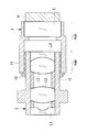
- an imaging unit for an endoscope according to this embodiment includes an objective lens unit frame 2 that holds an objective lens, and an imaging element holding frame that fits the objective lens unit frame 2 and holds the imaging element. 3 is provided.
- the objective lens unit frame 2 is on the inner side and the image sensor holding frame 3 is on the outer side when fitted.
- the objective lens unit frame 2 holds a plurality of lenses L1, L2, L3, and L4.
- the objective lens unit frame 2 has a fitting portion 10 at which the end on the imaging surface side is fitted with the imaging element holding frame 3.
- the image sensor holding frame 3 holds the image sensor 4 and the cover glass 5.
- the image sensor holding frame 3 has a fitting portion 11 whose end on the object plane side is fitted with the objective lens unit frame 2.
- the outer surface other than is configured to satisfy the following conditional expression.
- (alpha) is the infrared absorption factor per unit area of the outer surface of the said fitting part
- (beta) is the infrared absorption factor per unit area of outer surfaces other than the said fitting part.
- the image pickup device holding frame 3 is made of a metal material, and the outer surface of the fitting portion 11 among the outer surfaces of the image pickup device holding frame 3 is chrome plated.
- the outer surface is not plated or the like, and has a glossy metal surface with an exposed surface processed with a metal material. That is, since the outer surface of the fitting part 11 is chrome-plated and black compared with the metal surface of the outer surface other than the fitting part 11 among the outer surfaces of the image sensor holding frame 3, infrared rays are efficiently used. Absorb.
- the outer surface of the fitting portion is shown as “ ⁇ portion” and the outer surface other than the fitting portion is shown as “ ⁇ portion” in FIG.
- the outer surface (metal surface) other than the fitting portion 11 that is not plated is used.
- the infrared absorption rate per unit area is about 7%.
- the outer surface of the fitting portion 11 in which chromium is plated on stainless steel can improve the infrared absorption rate per unit area to about 16% due to the effect of the chromium oxide film used for chromium plating. .
- conditional expression (2) instead of the conditional expression (1), the infrared absorption rate per unit area on the outer surface of the fitting portion 11 can be further improved. ⁇ / ⁇ > 4 (2)
- the endoscope imaging unit configured in this way is assembled as follows. That is, as shown in FIG. 2, an adhesive 12 made of a thermosetting resin is applied to the outer surface of the fitting portion 10 or the inner surface of the fitting portion 11, and the objective lens unit frame 2 and the image sensor holding frame 3 After adjusting the interval, the adhesive 12 is heated and cured using infrared rays from the outside.
- FIG. 2 only one infrared lamp is illustrated in a simplified manner. However, since it is actually necessary to heat the entire fitting portion, a plurality of infrared lamps are arranged on the circumference and heated.
- the outer surface of the fitting portion 11 in the imaging element holding frame 3 located on the outer side when fitting with the objective lens unit frame 2 is heated by infrared irradiation as compared with the portion other than the fitting portion 11. It is easy to be configured. For this reason, only the fitting part 11 can be efficiently heated by the infrared irradiation with respect to the fitting part 11, the positional deviation resulting from the thermal expansion of a jig or a part can be suppressed, and a manufacturing error can be suppressed. The positioning accuracy between the objective lens and the image sensor can be improved.
- the imaging element holding frame 3 located outside is made of a metal material, and chrome plating is applied to the metal material.
- chrome plating is applied to the metal material.
- other black treatments may be used, for example, chromate treatment, anodizing, etc. Processing, nickel plating, etc. may be used.
- Any of the imaging element holding frame 3 and the objective lens unit frame 2 that can be plated black in relation to the metal material applied to the outer frame can be applied.
- stainless steel is shown as the metal material, it is not limited to stainless steel, and metal materials such as copper, brass, aluminum, and iron can also be applied.
- the objective lens unit frame 2 when the objective lens unit frame 2 and the image sensor holding frame 3 are fitted together, the objective lens unit frame 2 is configured to be inside, and the image sensor holding frame 3 is configured to be outside. It is not limited to this.
- the objective lens unit frame 2 can be configured to be on the outside, and the image sensor holding frame 3 can be configured to be on the inside. In this case, the outside of the fitting portion 10 of the objective lens unit frame 2 that is on the outside when fitted.
- the infrared absorption rate is increased by applying chrome plating or the like to the surface.
- the outer surface of the fitting portion 11 of the imaging element holding frame 3 is subjected to chromium plating.
- an infrared ray is applied to the outer surface of the fitting portion 11. It can also be set as the structure which apply
- an infrared absorbing material is applied to the outer surface of the fitting portion in the frame located outside when the objective lens unit and the image sensor unit are fitted, and the conditional expression (1) is satisfied.
- it can be set as the structure where the outer surface of a fitting part is easy to be heated by infrared irradiation compared with outer surfaces other than a fitting part.
- the infrared absorbing material for example, a black paint or a black paint mixed with a metal oxide or the like so as to efficiently absorb infrared rays can be applied.
- a single black ink may be used, and the infrared absorption rate per unit area can be further increased by mixing metal oxide powders such as chromium, copper, iron, nickel, and molybdenum in order to further improve the absorption rate.
- Such paint is applied only to the outer surface of the fitting portion of the frame located outside, and the outer surface other than the fitting portion is a metal surface, so that the infrared absorption rate of the fitting portion is other than the fitting portion. It can be increased compared to the part.
- the surface roughness of the outer surface of the fitting portion 11 is the surface roughness of the outer surface other than the fitting portion.
- the portion indicated by the Ra portion in FIG. 3 is a rough surface. That is, the outer surface of the fitting portion 11 and the fitting portion 11 among the outer surfaces of the imaging device holding frame 3 which is a frame located outside when the objective lens unit frame 2 and the imaging device holding frame 3 are fitted.
- Other outer surfaces satisfy the above-described conditional expression (1) and the following conditional expression (3).
- Ra is the maximum height of the surface roughness of the outer surface of the fitting part 11
- Rb is the maximum height of the surface roughness of the outer surface other than the fitting part 11.
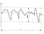
- the maximum height is a value ( ⁇ m) indicating a difference between the maximum value and the minimum value in the surface roughness, and when the surface roughness is measured in a certain reference range L as shown in FIG.
- the maximum value of the difference between the maximum height and the minimum height is expressed in ⁇ m.
- the outer surface of the fitting part 11 showing the maximum height Ra of the surface roughness is shown as Ra part, and the outer surface other than the fitting part 11 showing the maximum height Rb of the surface roughness is shown as Rb part. ing.
- the outer surface of the fitting portion 11 and the fitting portion at the stage of processing the frame.
- This can be realized by changing the rotational speed and feed amount of the cutting tool with an outer surface other than 11 or by sandblasting after machining.
- black processing such as plating, an imaging element holding frame in which the outer surface of the fitting portion 11 has a higher infrared absorption rate than the outer surface other than the fitting portion 11 can be configured.
- Ra 3.97 ⁇ Rb, which satisfies the condition of Ra> 3 ⁇ Rb.
- the endoscope imaging unit configured in this manner applies the adhesive 12 made of a thermosetting resin to the outer surface of the fitting portion 10 or the inner surface of the fitting portion 11, and images the objective lens unit frame 2 and the imaging unit. After adjusting the distance from the element holding frame 3, the adhesive 12 is heated and cured from outside using infrared rays.
- the surface roughness of the outer surface of the fitting portion 11 in the imaging element holding frame 3 positioned outside when fitting with the objective lens unit frame 2 is larger than that of the outer surface other than the fitting portion 11. It has a rough structure. For this reason, only the fitting part 11 can be efficiently heated by the infrared irradiation with respect to the fitting part 11, the positional deviation resulting from the thermal expansion of a jig or a part can be suppressed, and a manufacturing error can be suppressed. The positioning accuracy between the objective lens and the image sensor can be improved.
- the infrared absorptance ⁇ of the outer surface of the image sensor holding frame 3 positioned on the outer side during fitting is the outer surface of the objective lens unit frame 2 positioned on the inner side during fitting. It is configured to be higher than the infrared absorption rate ⁇ of the outer surface other than the fitting portion 10.
- the outer surface of the fitting portion 11 of the imaging element holding frame 3 showing the infrared absorption rate ⁇ is shown as ⁇ portion
- the outer surface other than the fitting portion 10 of the objective lens unit frame 2 showing the infrared absorption rate ⁇ It is shown as ⁇ part.
- ⁇ is the infrared absorption rate per unit area of the outer surface of the frame located on the outer side
- ⁇ is the infrared absorption rate per unit area of the outer surface other than the fitting portion of the outer surface of the frame located on the inner side. It is.
- ⁇ is the infrared absorption rate per unit area of the outer surface other than the fitting portion of the outer surface of the frame located on the inner side at the time of fitting.
- the entire outer surface including the fitting portion may have the same infrared absorption rate ⁇ . This means that in the case of irradiating infrared rays from the outside, the infrared rays do not hit the outer surface of the fitting portion of the frame located on the inner side during fitting, and either may be used.
- the imaging element holding frame 3 located on the outside and the objective lens unit frame 2 located on the inside are made of a metal material.
- stainless steel is used as the metal material, and the outer surface other than the fitting portion of the objective lens unit frame 2 on the inner side is exposed to the surface processed with the metal material without performing a treatment such as plating.
- the glossy metal surface can be used, and the outer surface of the fitting portion of the image sensor holding frame 3 on the outside can be plated with chromium.
- the outer peripheral surface of the fitting surface of the objective lens unit frame 2 located on the inner side is processed with a metal material without being subjected to a treatment such as plating similarly to the outer peripheral surface other than the fitting portion.
- the exposed surface becomes an exposed glossy metal surface.
- the imaging element holding frame 3 positioned outside is made of a metal material, and chrome plating is applied to the metal material.
- chrome plating is applied to the metal material.
- other black treatments may be used, for example, chromate treatment, anodizing, etc. Processing, nickel plating, etc. may be used.
- metal materials such as not only this but copper, brass, aluminum, iron, can also be applied.
- an infrared absorbing material may be applied. Examples of the infrared absorbing material are as described above.
- the surface roughness of the outer surface of the image sensor holding frame 3 positioned on the outer side during fitting is set to the outer surface other than the fitting portion 10 of the objective lens unit frame 2 positioned on the inner side. Make it rough.
- the outer surface of the image sensor holding frame 3 that is a frame located on the outer side and the objective lens unit frame 2 that is a frame located on the inner side satisfies the above-described conditional expression (4) and satisfies the following conditional expression (6).
- Rai is the maximum height of the surface roughness of the outer surface other than the fitting portion in the outer surface of the frame located on the inner side
- Rbo is the maximum height of the surface roughness of the outer surface of the frame located on the outer side. It is.
- the maximum height is a value ( ⁇ m) indicating a difference between the maximum value and the minimum value of the surface roughness.
- Rai is the maximum height of the surface roughness of the outer surface other than the fitting portion 10 among the outer surfaces of the inner frame, but the entire outer surface including the fitting portion of the inner frame. May have the same surface roughness Rai.
- the infrared rays do not hit the outer surface of the fitting portion of the frame located on the inner side during fitting, and either may be used.
- the outer surface other than the fitting portion 10 of the objective lens unit frame 2 showing the maximum height Rai of the surface roughness is shown as a Rai portion, and the imaging element holding frame 3 showing the maximum height Rbo of the surface roughness.
- the outer surface is shown as the Rbo part.
- the outer surface of the objective lens unit frame 2 positioned on the inner side is the outer surface other than the fitting portion 10.
- both the objective lens unit frame 2 and the image sensor holding frame 3 are made of a stainless material, and at least the outer surface is subjected to black plating.
- the infrared absorptance per unit area of the outer surface of the objective lens unit frame 2 positioned inside in the fitting portion, and the infrared absorptivity per unit area of the outer surface of the image sensor holding frame 3 positioned outside The ratio is ⁇ / ⁇ 1.81 times.
- the above conditional expression (6) is satisfied, and in this case, ⁇ / ⁇ is 2.4 times.
- the surface roughness of the outer peripheral surface of the fitting portion of the objective lens unit frame 2 located inside the fitting portion is the same as the surface roughness Rai of the outer peripheral surface other than the fitting portion. May be different.
- the black plating on the metal can be appropriately selected from chrome plating, chromate treatment, alumite treatment, nickel plating, and the like that can be processed black due to the relationship with the metal material.
- the objective lens holding frame 2 and the image sensor holding frame 3 are not limited to stainless steel, and various metal materials such as copper, brass, aluminum, and iron can be applied.
- An image sensor that uses a luminance signal is an example of an image sensor that uses such a reference amount.
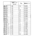
- FIG. 8 lists application examples 1 to 15 as examples of optical systems that require highly accurate alignment that satisfies the conditional expression (7).
Landscapes
- Health & Medical Sciences (AREA)
- Life Sciences & Earth Sciences (AREA)
- Surgery (AREA)
- Physics & Mathematics (AREA)
- Engineering & Computer Science (AREA)
- Optics & Photonics (AREA)
- Animal Behavior & Ethology (AREA)
- Heart & Thoracic Surgery (AREA)
- Veterinary Medicine (AREA)
- Biophysics (AREA)
- Nuclear Medicine, Radiotherapy & Molecular Imaging (AREA)
- Pathology (AREA)
- Radiology & Medical Imaging (AREA)
- Public Health (AREA)
- Biomedical Technology (AREA)
- General Health & Medical Sciences (AREA)
- Medical Informatics (AREA)
- Molecular Biology (AREA)
- Astronomy & Astrophysics (AREA)
- General Physics & Mathematics (AREA)
- Multimedia (AREA)
- Manufacturing & Machinery (AREA)
- Endoscopes (AREA)
- Instruments For Viewing The Inside Of Hollow Bodies (AREA)
- Lens Barrels (AREA)
Abstract
Description
本発明の第1の態様は、対物レンズを保持する対物レンズユニット枠と、該対物レンズユニット枠に嵌合し、撮像素子を保持する撮像素子保持枠と、を備え、前記対物レンズユニット枠と前記撮像素子保持枠とが、これらの嵌合部に塗布された熱硬化性樹脂により接着されて固定され、前記対物レンズユニット枠と前記撮像素子保持枠とが嵌合した際に外側に位置する枠の外表面のうち、前記嵌合部の外表面と前記嵌合部以外の外表面とが下記の条件式を満たす内視鏡用撮像ユニットを提供する。
α/β>2 …(1)
但し、αは前記嵌合部の外表面の単位面積当たりの赤外線吸収率であり、βは前記嵌合部以外の外表面の単位面積当たりの赤外線吸収率である。
α/β>4 …(2)
このようにすることで、嵌合部の赤外線吸収率を嵌合部以外の部分に比してより高めることができ、治具や部品の熱膨張に起因する位置ズレを抑制することができ、製造誤差を抑制して対物レンズと撮像素子との位置決め精度を向上させることができる。
Ra>3×Rb …(3)
但し、Raは前記嵌合部の外表面の表面粗さの最大高さであり、Rbは前記嵌合部以外の外表面の表面粗さの最大高さである。ここで、前記最大高さとは、前記表面粗さにおける最大値と最小値との差を示す値(μm)である。
ρ/γ>1.5 …(4)
但し、ρは外側に位置する枠における外表面の単位面積当たりの赤外線吸収率であり、γは内側に位置する枠における外表面のうち嵌合部以外の外表面の単位面積当たりの赤外線吸収率である。
ρ/γ>2 …(5)
このようにすることで、嵌合部の赤外線吸収率を嵌合部以外の部分に比してより高めることができ、治具や部品の熱膨張に起因する位置ズレを抑制することができ、製造誤差を抑制して対物レンズと撮像素子との位置決め精度を向上させることができる。
Rbo>3×Rai …(6)
但し、Raiは内側に位置する枠における外表面のうち嵌合部以外の外表面の表面粗さの最大高さであり、Rboは外側に位置する枠における外表面の表面粗さの最大高さである。ここで、前記最大高さとは、前記表面粗さにおける最大値と最小値との差を示す値(μm)である。
2.5×P×Fno<0.03 …(7)
但し、Pは撮像素子のピッチ、Fnoは対物光学系の有効Fナンバーである。
以下に、本発明の第1の実施形態に係る内視鏡用撮像ユニットについて図面を参照して説明する。
図1に示すように、本実施形態に係る内視鏡用撮像ユニットは、対物レンズを保持する対物レンズユニット枠2と、対物レンズユニット枠2と嵌合し撮像素子を保持する撮像素子保持枠3とを備えている。本実施形態においては、嵌合の際に、対物レンズユニット枠2が内側、撮像素子保持枠3が外側となる構成であることとして説明する。
撮像素子保持枠3は、撮像素子4及びカバーガラス5を保持している。撮像素子保持枠3は、その物体面側の端部が対物レンズユニット枠2と嵌合する嵌合部11となっている。
α/β>2 …(1)
但し、αは前記嵌合部の外表面の単位面積当たりの赤外線吸収率であり、βは前記嵌合部以外の外表面の単位面積当たりの赤外線吸収率である。
このとき、α=16%、β=7%、α/β=2.3倍となり、上記条件式(1)を満たす。
α/β>4 …(2)
上記した第1の実施形態においては、撮像素子保持枠3の嵌合部11の外表面にクロムメッキを施す構成としたが、このようなメッキ処理に代えて嵌合部11の外表面に赤外線吸収物質を塗布する構成とすることもできる。
以下に、本発明の第2の実施形態に係る内視鏡用撮像ユニットについて図面を参照して説明する。以下の説明において、上述した第1の実施形態に係る内視鏡用撮像ユニットと同一の構成には同符号を付し、その説明を省略する。また、本実施形態においても、第1の実施形態同様に、嵌合の際に、対物レンズユニット枠2が内側、撮像素子保持枠3が外側となる構成であることとして説明する。
但し、Raは嵌合部11の外表面の表面粗さの最大高さであり、Rbは嵌合部11以外の外表面の表面粗さの最大高さである。
ここで、最大高さとは、表面粗さにおける最大値と最小値との差を示す値(μm)であり、図4に示すように、表面粗さをある基準範囲Lで測定した場合の、最大高さと最少高さの差の最大値(図4中、Rmax)をμmで示したものである。
0.16×1.16×1.16×1.16×1.16=0.29
これは、メッキなどを施していないRb部に比べ、単位面積当たりの赤外線吸収率を29%程度にまで改善できたことになる。この場合、Ra=3.97×Rb となっており、Ra>3×Rbの条件を満たす。このとき、α=29%、メッキがされていない嵌合部11以外の外表面(金属表面)での単位面積当たりの赤外線吸収率β=7%となり、α/β=4.14倍となり、条件式(2)を満たし、効率よく必要な部分を加熱できる構成となっている。
以下に、本発明の第3の実施形態に係る内視鏡用撮像ユニットについて図面を参照して説明する。以下の説明において、上述した第1の実施形態に係る内視鏡用撮像ユニットと同一の構成には同符号を付し、その説明を省略する。また、本実施形態においても、第1の実施形態同様に、嵌合の際に、対物レンズユニット枠2が内側、撮像素子保持枠3が外側となる構成であることとして説明する。
ρ/γ>1.5 …(4)
但し、ρは外側に位置する枠における外表面の単位面積当たりの赤外線吸収率であり、γは内側に位置する枠における外表面のうち嵌合部以外の外表面の単位面積当たりの赤外線吸収率である。ここで、嵌合の際に内側に位置する枠における外表面のうち嵌合部以外の外表面の単位面積当たりの赤外線吸収率をγとしているが、嵌合の際に内側に位置する枠の嵌合部も含めた外表面全体が同じ赤外線吸収率γであってもよい。これは、外部より赤外線を照射する場合、嵌合の際に内側に位置する枠の嵌合部の外表面には赤外線が当たらないため、どちらであっても良いことを意味する。
上記条件式(4)に代えて、下記条件式(5)を適用することにより、より嵌合部における赤外線吸収率を高めることができる。
ρ/γ>2 …(5)
以下に、本発明の第4の実施形態に係る内視鏡用撮像ユニットについて図面を参照して説明する。以下の説明において、上述した第1の実施形態に係る内視鏡用撮像ユニットと同一の構成には同符号を付し、その説明を省略する。また、本実施形態においても、第1の実施形態同様に、嵌合の際に、対物レンズユニット枠2が内側、撮像素子保持枠3が外側となる構成であることとして説明する。
但し、Raiは内側に位置する枠における外表面のうち嵌合部以外の外表面の表面粗さの最大高さであり、Rboは外側に位置する枠における外表面の表面粗さの最大高さである。ここで、最大高さとは、表面粗さにおける高さの最大値と最小値との差を示す値(μm)である。ここで、Raiは内側に位置する枠における外表面のうち嵌合部10以外の外表面の表面粗さの最大高さとしているが、内側に位置する枠の嵌合部を含めた外表面全体が同じ表面粗さRaiであってもよい。これは、外部より赤外線を照射する場合、嵌合の際に内側に位置する枠の嵌合部の外表面には赤外線が当たらないため、どちらであっても良いことを意味する。
図6において、表面粗さの最大高さRaiを示す対物レンズユニット枠2の嵌合部10以外の外表面をRai部として示し、表面粗さの最大高さRboを示す撮像素子保持枠3の外表面をRbo部として示している。
このように、対物レンズユニット枠2及び撮像素子保持枠3が共に黒処理をされた構成においても、効率よく嵌合部、すなわち接着して固定すべき部位のみを加熱、接着剤12を硬化することができる。
また、本実施形態において、嵌合部で内側に位置する対物レンズユニット枠2の嵌合部の外周面の表面粗さが、嵌合部以外の外周面の表面粗さRaiと同じであってもよく、異なっていてもよい。
2.5×P×Fno<0.03 …(7)
但し、Pは撮像素子のピッチ、Fnoは対物光学系の有効Fナンバーである。
δ/D=ΔPinto/f
ΔPinto=δ・f/D
が成り立つので、
δ=2.5Pとすると、
ΔPinto=Fno×2.5×P
が得られるためである。
但し、Dは対物レンズの有効口径、fは焦点距離、δは像面上で許容されるボケの直径である。
3 撮像素子保持枠
4 撮像素子
5 カバーガラス
10 嵌合部
11 嵌合部
12 接着剤
L1 レンズ
L2 レンズ
L3 レンズ
L4 レンズ
Claims (7)
- 対物レンズを保持する対物レンズユニット枠と、
該対物レンズユニット枠に嵌合し、撮像素子を保持する撮像素子保持枠と、を備え、
前記対物レンズユニット枠と前記撮像素子保持枠とが、これらの嵌合部に塗布された熱硬化性樹脂により接着されて固定され、
前記対物レンズユニット枠と前記撮像素子保持枠とが嵌合した際に外側に位置する枠の外表面のうち、前記嵌合部の外表面と前記嵌合部以外の外表面とが下記の条件式を満たす内視鏡用撮像ユニット。
α/β>2 …(1)
但し、αは前記嵌合部の外表面の単位面積当たりの赤外線吸収率であり、βは前記嵌合部以外の外表面の単位面積当たりの赤外線吸収率である。 - 以下の条件式(2)を満足する請求項1記載の内視鏡用撮像ユニット。
α/β>4 …(2) - 以下の条件式(3)を満足する請求項1又は請求項2記載の内視鏡用撮像ユニット。
Ra>3×Rb …(3)
但し、Raは前記外側に位置する枠の外表面のうち前記嵌合部の外表面の表面粗さの最大高さであり、Rbは前記外側に位置する枠の外表面のうち前記嵌合部以外の外表面の表面粗さの最大高さである。ここで、前記最大高さとは、前記表面粗さにおける高さの最大値と最小値との差を示す値(μm)である。 - 対物レンズを保持する対物レンズユニット枠と、
該対物レンズユニット枠に嵌合し、撮像素子を保持する撮像素子保持枠と、を備え、
前記対物レンズユニット枠と前記撮像素子保持枠とが、これらの嵌合部に塗布された熱硬化性樹脂により接着されて固定され、
前記対物レンズユニット枠と前記撮像素子保持枠とが嵌合した際に外側に位置する枠の外表面と、内側に位置する枠の外表面のうち前記嵌合部以外の外表面とが下記の条件式を(4)満たす内視鏡用撮像ユニット。
ρ/γ>1.5 …(4)
但し、ρは外側に位置する枠における外表面の単位面積当たりの赤外線吸収率であり、γは内側に位置する枠における外表面のうち嵌合部以外の外表面の単位面積当たりの赤外線吸収率である。 - 以下の条件式(5)を満足する請求項4記載の内視鏡用撮像ユニット。
ρ/γ>2 …(5) - 以下の条件式(6)を満足する請求項4又は請求項5記載の内視鏡用撮像ユニット。
Rbo>3×Rai …(6)
但し、Raiは内側に位置する枠における外表面のうち嵌合部以外の外表面の表面粗さの最大高さであり、Rboは外側に位置する枠における外表面の表面粗さの最大高さである。ここで、前記最大高さとは、前記表面粗さにおける高さの最大値と最小値との差を示す値(μm)である。 - 以下の条件式(7)を満足する請求項1乃至請求項6の何れか1項記載の内視鏡用撮像ユニット。
2.5×P×Fno<0.03 …(7)
但し、Pは撮像素子のピッチ、Fnoは対物レンズの有効Fナンバーである。
Priority Applications (4)
| Application Number | Priority Date | Filing Date | Title |
|---|---|---|---|
| JP2015546762A JP5851668B1 (ja) | 2014-03-28 | 2015-02-03 | 内視鏡用撮像ユニット |
| EP15768959.7A EP3123920A4 (en) | 2014-03-28 | 2015-02-03 | Imaging unit for endoscopes |
| CN201580001659.1A CN105473050B (zh) | 2014-03-28 | 2015-02-03 | 内窥镜用摄像单元 |
| US15/050,763 US20160166132A1 (en) | 2014-03-28 | 2016-02-23 | Endoscopic Image-Acquisition Unit |
Applications Claiming Priority (2)
| Application Number | Priority Date | Filing Date | Title |
|---|---|---|---|
| JP2014068942 | 2014-03-28 | ||
| JP2014-068942 | 2014-03-28 |
Related Child Applications (1)
| Application Number | Title | Priority Date | Filing Date |
|---|---|---|---|
| US15/050,763 Continuation US20160166132A1 (en) | 2014-03-28 | 2016-02-23 | Endoscopic Image-Acquisition Unit |
Publications (1)
| Publication Number | Publication Date |
|---|---|
| WO2015146290A1 true WO2015146290A1 (ja) | 2015-10-01 |
Family
ID=54194830
Family Applications (1)
| Application Number | Title | Priority Date | Filing Date |
|---|---|---|---|
| PCT/JP2015/052962 Ceased WO2015146290A1 (ja) | 2014-03-28 | 2015-02-03 | 内視鏡用撮像ユニット |
Country Status (5)
| Country | Link |
|---|---|
| US (1) | US20160166132A1 (ja) |
| EP (1) | EP3123920A4 (ja) |
| JP (1) | JP5851668B1 (ja) |
| CN (1) | CN105473050B (ja) |
| WO (1) | WO2015146290A1 (ja) |
Families Citing this family (3)
| Publication number | Priority date | Publication date | Assignee | Title |
|---|---|---|---|---|
| JP2017185086A (ja) * | 2016-04-07 | 2017-10-12 | オリンパス株式会社 | 医療機器および医療機器用熱硬化型接着剤 |
| EP3599983B1 (en) | 2017-03-24 | 2023-11-15 | Covidien LP | Endoscopes |
| JP6527646B2 (ja) * | 2017-05-26 | 2019-06-05 | オリンパス株式会社 | 光学ユニット |
Citations (3)
| Publication number | Priority date | Publication date | Assignee | Title |
|---|---|---|---|---|
| JPH09192093A (ja) * | 1996-01-23 | 1997-07-29 | Olympus Optical Co Ltd | 撮像装置 |
| JP2008125902A (ja) * | 2006-11-22 | 2008-06-05 | Pentax Corp | 内視鏡スコープおよび内視鏡スコープの製造方法 |
| WO2011092904A1 (ja) * | 2010-02-01 | 2011-08-04 | オリンパスメディカルシステムズ株式会社 | 内視鏡先端部構造 |
Family Cites Families (9)
| Publication number | Priority date | Publication date | Assignee | Title |
|---|---|---|---|---|
| US5305736A (en) * | 1991-04-26 | 1994-04-26 | Asahi Kogaku Kogyo Kabushiki Kaisha | Distal end part of endoscope |
| US6547721B1 (en) * | 1998-08-07 | 2003-04-15 | Olympus Optical Co., Ltd. | Endoscope capable of being autoclaved |
| JP3297033B2 (ja) * | 2000-02-02 | 2002-07-02 | オリンパス光学工業株式会社 | 内視鏡 |
| JP2002336190A (ja) * | 2001-03-12 | 2002-11-26 | Olympus Optical Co Ltd | 内視鏡 |
| US6936735B2 (en) * | 2002-08-27 | 2005-08-30 | Emd Chemicals, Inc. | Photostable cationic organic sunscreen compounds and compositions obtained therefrom |
| JP3967337B2 (ja) * | 2004-05-14 | 2007-08-29 | オリンパス株式会社 | 内視鏡および内視鏡装置 |
| JP4864624B2 (ja) * | 2006-09-28 | 2012-02-01 | Hoya株式会社 | 電子内視鏡の先端光学ユニット |
| JP2008018254A (ja) * | 2007-08-21 | 2008-01-31 | Olympus Corp | カプセル型内視鏡 |
| JP2010269072A (ja) * | 2009-05-25 | 2010-12-02 | Hoya Corp | 固体撮像装置及びその製造方法 |
-
2015
- 2015-02-03 EP EP15768959.7A patent/EP3123920A4/en not_active Withdrawn
- 2015-02-03 WO PCT/JP2015/052962 patent/WO2015146290A1/ja not_active Ceased
- 2015-02-03 CN CN201580001659.1A patent/CN105473050B/zh not_active Expired - Fee Related
- 2015-02-03 JP JP2015546762A patent/JP5851668B1/ja active Active
-
2016
- 2016-02-23 US US15/050,763 patent/US20160166132A1/en not_active Abandoned
Patent Citations (3)
| Publication number | Priority date | Publication date | Assignee | Title |
|---|---|---|---|---|
| JPH09192093A (ja) * | 1996-01-23 | 1997-07-29 | Olympus Optical Co Ltd | 撮像装置 |
| JP2008125902A (ja) * | 2006-11-22 | 2008-06-05 | Pentax Corp | 内視鏡スコープおよび内視鏡スコープの製造方法 |
| WO2011092904A1 (ja) * | 2010-02-01 | 2011-08-04 | オリンパスメディカルシステムズ株式会社 | 内視鏡先端部構造 |
Non-Patent Citations (1)
| Title |
|---|
| See also references of EP3123920A4 * |
Also Published As
| Publication number | Publication date |
|---|---|
| JPWO2015146290A1 (ja) | 2017-04-13 |
| CN105473050A (zh) | 2016-04-06 |
| EP3123920A1 (en) | 2017-02-01 |
| JP5851668B1 (ja) | 2016-02-03 |
| EP3123920A4 (en) | 2017-12-27 |
| CN105473050B (zh) | 2017-11-07 |
| US20160166132A1 (en) | 2016-06-16 |
Similar Documents
| Publication | Publication Date | Title |
|---|---|---|
| JP5853179B2 (ja) | 内視鏡及び内視鏡の製造方法 | |
| JP5866565B1 (ja) | 内視鏡 | |
| CN102998765B (zh) | 相机模组组装方法及相机模组 | |
| JP5893801B2 (ja) | 撮像装置 | |
| JP5851668B1 (ja) | 内視鏡用撮像ユニット | |
| JP6006458B1 (ja) | 内視鏡用撮像ユニット | |
| US8472797B2 (en) | Image capturing lens system | |
| CN104822307B (zh) | 内窥镜用摄像单元以及内窥镜装置 | |
| WO2017022500A1 (ja) | 光学組立体の接着固定方法および光学組立体 | |
| JP5958727B2 (ja) | 内視鏡 | |
| JP5914784B2 (ja) | 内視鏡用撮像装置及び内視鏡用撮像装置の組立方法 | |
| JP2014033730A5 (ja) | ||
| JP6675418B2 (ja) | 内視鏡用結像ユニット及び結像ユニットの製造方法 | |
| JP2015080646A (ja) | 内視鏡用レンズユニットおよびこれを備えた内視鏡 | |
| JP6862146B2 (ja) | 光学機器 | |
| JP2005308779A (ja) | レンズ装置の温度補償構造 | |
| JP2016020951A (ja) | レンズ鏡筒および光学機器 | |
| JP6774530B2 (ja) | レンズユニットおよびカメラモジュール | |
| JP6226207B2 (ja) | 内視鏡 | |
| US9876947B2 (en) | Optical apparatus and image capturing apparatus | |
| WO2025224792A1 (ja) | 撮像ユニット、内視鏡、およびレンズ枠 |
Legal Events
| Date | Code | Title | Description |
|---|---|---|---|
| WWE | Wipo information: entry into national phase |
Ref document number: 201580001659.1 Country of ref document: CN |
|
| ENP | Entry into the national phase |
Ref document number: 2015546762 Country of ref document: JP Kind code of ref document: A |
|
| 121 | Ep: the epo has been informed by wipo that ep was designated in this application |
Ref document number: 15768959 Country of ref document: EP Kind code of ref document: A1 |
|
| NENP | Non-entry into the national phase |
Ref country code: DE |
|
| REEP | Request for entry into the european phase |
Ref document number: 2015768959 Country of ref document: EP |
|
| WWE | Wipo information: entry into national phase |
Ref document number: 2015768959 Country of ref document: EP |