WO2015146350A1 - 電動機の制御装置 - Google Patents
電動機の制御装置 Download PDFInfo
- Publication number
- WO2015146350A1 WO2015146350A1 PCT/JP2015/053973 JP2015053973W WO2015146350A1 WO 2015146350 A1 WO2015146350 A1 WO 2015146350A1 JP 2015053973 W JP2015053973 W JP 2015053973W WO 2015146350 A1 WO2015146350 A1 WO 2015146350A1
- Authority
- WO
- WIPO (PCT)
- Prior art keywords
- electric motor
- inverter
- rotor
- control device
- phase
- Prior art date
- Legal status (The legal status is an assumption and is not a legal conclusion. Google has not performed a legal analysis and makes no representation as to the accuracy of the status listed.)
- Ceased
Links
Images



Classifications
-
- H—ELECTRICITY
- H02—GENERATION; CONVERSION OR DISTRIBUTION OF ELECTRIC POWER
- H02P—CONTROL OR REGULATION OF ELECTRIC MOTORS, ELECTRIC GENERATORS OR DYNAMO-ELECTRIC CONVERTERS; CONTROLLING TRANSFORMERS, REACTORS OR CHOKE COILS
- H02P6/00—Arrangements for controlling synchronous motors or other dynamo-electric motors using electronic commutation dependent on the rotor position; Electronic commutators therefor
- H02P6/20—Arrangements for starting
-
- B—PERFORMING OPERATIONS; TRANSPORTING
- B60—VEHICLES IN GENERAL
- B60L—PROPULSION OF ELECTRICALLY-PROPELLED VEHICLES; SUPPLYING ELECTRIC POWER FOR AUXILIARY EQUIPMENT OF ELECTRICALLY-PROPELLED VEHICLES; ELECTRODYNAMIC BRAKE SYSTEMS FOR VEHICLES IN GENERAL; MAGNETIC SUSPENSION OR LEVITATION FOR VEHICLES; MONITORING OPERATING VARIABLES OF ELECTRICALLY-PROPELLED VEHICLES; ELECTRIC SAFETY DEVICES FOR ELECTRICALLY-PROPELLED VEHICLES
- B60L50/00—Electric propulsion with power supplied within the vehicle
- B60L50/10—Electric propulsion with power supplied within the vehicle using propulsion power supplied by engine-driven generators, e.g. generators driven by combustion engines
- B60L50/11—Electric propulsion with power supplied within the vehicle using propulsion power supplied by engine-driven generators, e.g. generators driven by combustion engines using DC generators and DC motors
-
- B—PERFORMING OPERATIONS; TRANSPORTING
- B60—VEHICLES IN GENERAL
- B60L—PROPULSION OF ELECTRICALLY-PROPELLED VEHICLES; SUPPLYING ELECTRIC POWER FOR AUXILIARY EQUIPMENT OF ELECTRICALLY-PROPELLED VEHICLES; ELECTRODYNAMIC BRAKE SYSTEMS FOR VEHICLES IN GENERAL; MAGNETIC SUSPENSION OR LEVITATION FOR VEHICLES; MONITORING OPERATING VARIABLES OF ELECTRICALLY-PROPELLED VEHICLES; ELECTRIC SAFETY DEVICES FOR ELECTRICALLY-PROPELLED VEHICLES
- B60L50/00—Electric propulsion with power supplied within the vehicle
- B60L50/10—Electric propulsion with power supplied within the vehicle using propulsion power supplied by engine-driven generators, e.g. generators driven by combustion engines
- B60L50/16—Electric propulsion with power supplied within the vehicle using propulsion power supplied by engine-driven generators, e.g. generators driven by combustion engines with provision for separate direct mechanical propulsion
-
- B—PERFORMING OPERATIONS; TRANSPORTING
- B60—VEHICLES IN GENERAL
- B60L—PROPULSION OF ELECTRICALLY-PROPELLED VEHICLES; SUPPLYING ELECTRIC POWER FOR AUXILIARY EQUIPMENT OF ELECTRICALLY-PROPELLED VEHICLES; ELECTRODYNAMIC BRAKE SYSTEMS FOR VEHICLES IN GENERAL; MAGNETIC SUSPENSION OR LEVITATION FOR VEHICLES; MONITORING OPERATING VARIABLES OF ELECTRICALLY-PROPELLED VEHICLES; ELECTRIC SAFETY DEVICES FOR ELECTRICALLY-PROPELLED VEHICLES
- B60L50/00—Electric propulsion with power supplied within the vehicle
- B60L50/50—Electric propulsion with power supplied within the vehicle using propulsion power supplied by batteries or fuel cells
- B60L50/51—Electric propulsion with power supplied within the vehicle using propulsion power supplied by batteries or fuel cells characterised by AC-motors
-
- B—PERFORMING OPERATIONS; TRANSPORTING
- B60—VEHICLES IN GENERAL
- B60R—VEHICLES, VEHICLE FITTINGS, OR VEHICLE PARTS, NOT OTHERWISE PROVIDED FOR
- B60R16/00—Electric or fluid circuits specially adapted for vehicles and not otherwise provided for; Arrangement of elements of electric or fluid circuits specially adapted for vehicles and not otherwise provided for
- B60R16/02—Electric or fluid circuits specially adapted for vehicles and not otherwise provided for; Arrangement of elements of electric or fluid circuits specially adapted for vehicles and not otherwise provided for electric constitutive elements
- B60R16/03—Electric or fluid circuits specially adapted for vehicles and not otherwise provided for; Arrangement of elements of electric or fluid circuits specially adapted for vehicles and not otherwise provided for electric constitutive elements for supply of electrical power to vehicle subsystems or for
- B60R16/033—Electric or fluid circuits specially adapted for vehicles and not otherwise provided for; Arrangement of elements of electric or fluid circuits specially adapted for vehicles and not otherwise provided for electric constitutive elements for supply of electrical power to vehicle subsystems or for characterised by the use of electrical cells or batteries
-
- F—MECHANICAL ENGINEERING; LIGHTING; HEATING; WEAPONS; BLASTING
- F02—COMBUSTION ENGINES; HOT-GAS OR COMBUSTION-PRODUCT ENGINE PLANTS
- F02B—INTERNAL-COMBUSTION PISTON ENGINES; COMBUSTION ENGINES IN GENERAL
- F02B39/00—Component parts, details, or accessories relating to, driven charging or scavenging pumps, not provided for in groups F02B33/00 - F02B37/00
- F02B39/02—Drives of pumps; Varying pump drive gear ratio
- F02B39/08—Non-mechanical drives, e.g. fluid drives having variable gear ratio
- F02B39/10—Non-mechanical drives, e.g. fluid drives having variable gear ratio electric
-
- F—MECHANICAL ENGINEERING; LIGHTING; HEATING; WEAPONS; BLASTING
- F02—COMBUSTION ENGINES; HOT-GAS OR COMBUSTION-PRODUCT ENGINE PLANTS
- F02D—CONTROLLING COMBUSTION ENGINES
- F02D41/00—Electrical control of supply of combustible mixture or its constituents
- F02D41/0002—Controlling intake air
- F02D41/0007—Controlling intake air for control of turbo-charged or super-charged engines
-
- F—MECHANICAL ENGINEERING; LIGHTING; HEATING; WEAPONS; BLASTING
- F02—COMBUSTION ENGINES; HOT-GAS OR COMBUSTION-PRODUCT ENGINE PLANTS
- F02D—CONTROLLING COMBUSTION ENGINES
- F02D41/00—Electrical control of supply of combustible mixture or its constituents
- F02D41/24—Electrical control of supply of combustible mixture or its constituents characterised by the use of digital means
- F02D41/26—Electrical control of supply of combustible mixture or its constituents characterised by the use of digital means using computer, e.g. microprocessor
-
- H—ELECTRICITY
- H02—GENERATION; CONVERSION OR DISTRIBUTION OF ELECTRIC POWER
- H02P—CONTROL OR REGULATION OF ELECTRIC MOTORS, ELECTRIC GENERATORS OR DYNAMO-ELECTRIC CONVERTERS; CONTROLLING TRANSFORMERS, REACTORS OR CHOKE COILS
- H02P1/00—Arrangements for starting electric motors or dynamo-electric converters
- H02P1/02—Details of starting control
- H02P1/029—Restarting, e.g. after power failure
-
- H—ELECTRICITY
- H02—GENERATION; CONVERSION OR DISTRIBUTION OF ELECTRIC POWER
- H02P—CONTROL OR REGULATION OF ELECTRIC MOTORS, ELECTRIC GENERATORS OR DYNAMO-ELECTRIC CONVERTERS; CONTROLLING TRANSFORMERS, REACTORS OR CHOKE COILS
- H02P27/00—Arrangements or methods for the control of AC motors characterised by the kind of supply voltage
- H02P27/04—Arrangements or methods for the control of AC motors characterised by the kind of supply voltage using variable-frequency supply voltage, e.g. inverter or converter supply voltage
- H02P27/06—Arrangements or methods for the control of AC motors characterised by the kind of supply voltage using variable-frequency supply voltage, e.g. inverter or converter supply voltage using DC to AC converters or inverters
-
- H—ELECTRICITY
- H02—GENERATION; CONVERSION OR DISTRIBUTION OF ELECTRIC POWER
- H02P—CONTROL OR REGULATION OF ELECTRIC MOTORS, ELECTRIC GENERATORS OR DYNAMO-ELECTRIC CONVERTERS; CONTROLLING TRANSFORMERS, REACTORS OR CHOKE COILS
- H02P6/00—Arrangements for controlling synchronous motors or other dynamo-electric motors using electronic commutation dependent on the rotor position; Electronic commutators therefor
- H02P6/14—Electronic commutators
- H02P6/16—Circuit arrangements for detecting position
- H02P6/18—Circuit arrangements for detecting position without separate position detecting elements
-
- H—ELECTRICITY
- H02—GENERATION; CONVERSION OR DISTRIBUTION OF ELECTRIC POWER
- H02P—CONTROL OR REGULATION OF ELECTRIC MOTORS, ELECTRIC GENERATORS OR DYNAMO-ELECTRIC CONVERTERS; CONTROLLING TRANSFORMERS, REACTORS OR CHOKE COILS
- H02P6/00—Arrangements for controlling synchronous motors or other dynamo-electric motors using electronic commutation dependent on the rotor position; Electronic commutators therefor
- H02P6/14—Electronic commutators
- H02P6/16—Circuit arrangements for detecting position
- H02P6/18—Circuit arrangements for detecting position without separate position detecting elements
- H02P6/181—Circuit arrangements for detecting position without separate position detecting elements using different methods depending on the speed
-
- H—ELECTRICITY
- H02—GENERATION; CONVERSION OR DISTRIBUTION OF ELECTRIC POWER
- H02P—CONTROL OR REGULATION OF ELECTRIC MOTORS, ELECTRIC GENERATORS OR DYNAMO-ELECTRIC CONVERTERS; CONTROLLING TRANSFORMERS, REACTORS OR CHOKE COILS
- H02P6/00—Arrangements for controlling synchronous motors or other dynamo-electric motors using electronic commutation dependent on the rotor position; Electronic commutators therefor
- H02P6/14—Electronic commutators
- H02P6/16—Circuit arrangements for detecting position
- H02P6/18—Circuit arrangements for detecting position without separate position detecting elements
- H02P6/182—Circuit arrangements for detecting position without separate position detecting elements using back-emf in windings
-
- B—PERFORMING OPERATIONS; TRANSPORTING
- B60—VEHICLES IN GENERAL
- B60L—PROPULSION OF ELECTRICALLY-PROPELLED VEHICLES; SUPPLYING ELECTRIC POWER FOR AUXILIARY EQUIPMENT OF ELECTRICALLY-PROPELLED VEHICLES; ELECTRODYNAMIC BRAKE SYSTEMS FOR VEHICLES IN GENERAL; MAGNETIC SUSPENSION OR LEVITATION FOR VEHICLES; MONITORING OPERATING VARIABLES OF ELECTRICALLY-PROPELLED VEHICLES; ELECTRIC SAFETY DEVICES FOR ELECTRICALLY-PROPELLED VEHICLES
- B60L2240/00—Control parameters of input or output; Target parameters
- B60L2240/40—Drive Train control parameters
- B60L2240/42—Drive Train control parameters related to electric machines
- B60L2240/421—Speed
-
- B—PERFORMING OPERATIONS; TRANSPORTING
- B60—VEHICLES IN GENERAL
- B60L—PROPULSION OF ELECTRICALLY-PROPELLED VEHICLES; SUPPLYING ELECTRIC POWER FOR AUXILIARY EQUIPMENT OF ELECTRICALLY-PROPELLED VEHICLES; ELECTRODYNAMIC BRAKE SYSTEMS FOR VEHICLES IN GENERAL; MAGNETIC SUSPENSION OR LEVITATION FOR VEHICLES; MONITORING OPERATING VARIABLES OF ELECTRICALLY-PROPELLED VEHICLES; ELECTRIC SAFETY DEVICES FOR ELECTRICALLY-PROPELLED VEHICLES
- B60L2240/00—Control parameters of input or output; Target parameters
- B60L2240/40—Drive Train control parameters
- B60L2240/52—Drive Train control parameters related to converters
- B60L2240/526—Operating parameters
-
- B—PERFORMING OPERATIONS; TRANSPORTING
- B60—VEHICLES IN GENERAL
- B60L—PROPULSION OF ELECTRICALLY-PROPELLED VEHICLES; SUPPLYING ELECTRIC POWER FOR AUXILIARY EQUIPMENT OF ELECTRICALLY-PROPELLED VEHICLES; ELECTRODYNAMIC BRAKE SYSTEMS FOR VEHICLES IN GENERAL; MAGNETIC SUSPENSION OR LEVITATION FOR VEHICLES; MONITORING OPERATING VARIABLES OF ELECTRICALLY-PROPELLED VEHICLES; ELECTRIC SAFETY DEVICES FOR ELECTRICALLY-PROPELLED VEHICLES
- B60L2260/00—Operating Modes
- B60L2260/20—Drive modes; Transition between modes
- B60L2260/26—Transition between different drive modes
-
- B—PERFORMING OPERATIONS; TRANSPORTING
- B60—VEHICLES IN GENERAL
- B60Y—INDEXING SCHEME RELATING TO ASPECTS CROSS-CUTTING VEHICLE TECHNOLOGY
- B60Y2400/00—Special features of vehicle units
- B60Y2400/11—Electric energy storages
- B60Y2400/112—Batteries
-
- B—PERFORMING OPERATIONS; TRANSPORTING
- B60—VEHICLES IN GENERAL
- B60Y—INDEXING SCHEME RELATING TO ASPECTS CROSS-CUTTING VEHICLE TECHNOLOGY
- B60Y2400/00—Special features of vehicle units
- B60Y2400/61—Arrangements of controllers for electric machines, e.g. inverters
-
- F—MECHANICAL ENGINEERING; LIGHTING; HEATING; WEAPONS; BLASTING
- F02—COMBUSTION ENGINES; HOT-GAS OR COMBUSTION-PRODUCT ENGINE PLANTS
- F02D—CONTROLLING COMBUSTION ENGINES
- F02D2200/00—Input parameters for engine control
- F02D2200/50—Input parameters for engine control said parameters being related to the vehicle or its components
-
- F—MECHANICAL ENGINEERING; LIGHTING; HEATING; WEAPONS; BLASTING
- F02—COMBUSTION ENGINES; HOT-GAS OR COMBUSTION-PRODUCT ENGINE PLANTS
- F02D—CONTROLLING COMBUSTION ENGINES
- F02D2400/00—Control systems adapted for specific engine types; Special features of engine control systems not otherwise provided for; Power supply, connectors or cabling for engine control systems
- F02D2400/14—Power supply for engine control systems
-
- H—ELECTRICITY
- H02—GENERATION; CONVERSION OR DISTRIBUTION OF ELECTRIC POWER
- H02P—CONTROL OR REGULATION OF ELECTRIC MOTORS, ELECTRIC GENERATORS OR DYNAMO-ELECTRIC CONVERTERS; CONTROLLING TRANSFORMERS, REACTORS OR CHOKE COILS
- H02P2203/00—Indexing scheme relating to controlling arrangements characterised by the means for detecting the position of the rotor
- H02P2203/03—Determination of the rotor position, e.g. initial rotor position, during standstill or low speed operation
-
- Y—GENERAL TAGGING OF NEW TECHNOLOGICAL DEVELOPMENTS; GENERAL TAGGING OF CROSS-SECTIONAL TECHNOLOGIES SPANNING OVER SEVERAL SECTIONS OF THE IPC; TECHNICAL SUBJECTS COVERED BY FORMER USPC CROSS-REFERENCE ART COLLECTIONS [XRACs] AND DIGESTS
- Y02—TECHNOLOGIES OR APPLICATIONS FOR MITIGATION OR ADAPTATION AGAINST CLIMATE CHANGE
- Y02T—CLIMATE CHANGE MITIGATION TECHNOLOGIES RELATED TO TRANSPORTATION
- Y02T10/00—Road transport of goods or passengers
- Y02T10/60—Other road transportation technologies with climate change mitigation effect
- Y02T10/64—Electric machine technologies in electromobility
-
- Y—GENERAL TAGGING OF NEW TECHNOLOGICAL DEVELOPMENTS; GENERAL TAGGING OF CROSS-SECTIONAL TECHNOLOGIES SPANNING OVER SEVERAL SECTIONS OF THE IPC; TECHNICAL SUBJECTS COVERED BY FORMER USPC CROSS-REFERENCE ART COLLECTIONS [XRACs] AND DIGESTS
- Y02—TECHNOLOGIES OR APPLICATIONS FOR MITIGATION OR ADAPTATION AGAINST CLIMATE CHANGE
- Y02T—CLIMATE CHANGE MITIGATION TECHNOLOGIES RELATED TO TRANSPORTATION
- Y02T10/00—Road transport of goods or passengers
- Y02T10/60—Other road transportation technologies with climate change mitigation effect
- Y02T10/70—Energy storage systems for electromobility, e.g. batteries
-
- Y—GENERAL TAGGING OF NEW TECHNOLOGICAL DEVELOPMENTS; GENERAL TAGGING OF CROSS-SECTIONAL TECHNOLOGIES SPANNING OVER SEVERAL SECTIONS OF THE IPC; TECHNICAL SUBJECTS COVERED BY FORMER USPC CROSS-REFERENCE ART COLLECTIONS [XRACs] AND DIGESTS
- Y02—TECHNOLOGIES OR APPLICATIONS FOR MITIGATION OR ADAPTATION AGAINST CLIMATE CHANGE
- Y02T—CLIMATE CHANGE MITIGATION TECHNOLOGIES RELATED TO TRANSPORTATION
- Y02T10/00—Road transport of goods or passengers
- Y02T10/60—Other road transportation technologies with climate change mitigation effect
- Y02T10/7072—Electromobility specific charging systems or methods for batteries, ultracapacitors, supercapacitors or double-layer capacitors
Definitions
- the present invention relates to a sensorless motor control device.
- the phase of the magnetic pole of the rotor is detected with respect to the stator to prevent step-out.
- a method using a resolver or rotary encoder sensor is known, but using the above sensor increases the cost and size, so a method of starting the motor without a sensor is adopted. There is.
- the inverter that supplies power to the motor receives the start signal, sets the position of the magnetic pole of the rotor to a predetermined position with respect to the stator (phase detection), and phase detection is completed.
- the rotor is rotated later, and the rotation is set to the target rotational speed.
- the time from when the start signal is received until the rotor speed reaches the target rotational speed is increased only by the time that does not contribute to setting the rotor rotational speed to the target rotational speed (the time required for phase detection).
- the time required for phase detection accounts for a large proportion of the time from when the activation signal is received until the target rotational speed is reached.
- an electric supercharger that supercharges an internal combustion engine until the supercharger that supercharges the internal combustion engine mounted on the vehicle starts to work is intended to accelerate the vehicle to a target speed quickly. Yes.
- the rotational speed of the rotor of the electric motor provided in the electric supercharger can be made the target rotational speed in a short time
- the vehicle can be accelerated to the target speed quickly. That is, the vehicle can be accelerated to the target speed quickly if the time from receiving the activation signal output to the inverter in conjunction with the depression of the accelerator until the target rotational speed is reached can be shortened. Therefore, it is desired to reduce the time required for rotor phase detection that does not contribute to vehicle acceleration.
- the present invention relates to a sensorless motor control device that can shorten the time from when the start signal is received until the rotor reaches the target rotational speed by completing the phase detection of the rotor before receiving the start signal.
- the purpose is to provide.
- the motor control device which is one of the embodiments has an inverter and a phase detector.
- the inverter drives a sensorless motor.
- the phase detection unit causes the inverter to perform phase detection for setting the magnetic pole of the rotor to a predetermined position with respect to the stator of the electric motor before the inverter receives a start signal for starting the electric motor.
- the phase detection unit causes the inverter to detect the phase when the rotational speed of the rotor becomes equal to or lower than a predetermined rotational speed after receiving the start signal and rotating the rotor.
- phase holding unit that outputs a holding current for holding a predetermined position until a start signal is received after the phase detection is provided.
- the phase holding unit increases or decreases the holding current according to the measured intake air amount and outputs it to the inverter.
- the motor control device controls an inverter and a motor provided in the electric supercharger.
- FIG. 1 is a diagram illustrating an embodiment of a control device mounted on a vehicle having an electric supercharger.
- FIG. 2 is a diagram illustrating an example of the sensorless electric motor from when the inverter receives the start signal until the target rotational speed is reached.
- FIG. 3 is a diagram illustrating an example of a vehicle including an electric supercharger having a sensorless electric motor until it reaches a target speed after receiving an activation signal.
- FIG. 4 is a diagram for explaining the first process and the second process.
- FIG. 5 is a diagram showing the relationship between the flow rate and the holding current.
- FIG. 6 is a flowchart showing an embodiment of the operation of the control unit.
- FIG. 1 is a diagram showing an embodiment of an apparatus mounted on a vehicle having an electric supercharger.
- this example demonstrates using the electric motor of an electric supercharger, an electric motor is not limited to what is provided in the electric supercharger.
- An apparatus 1 shown in FIG. 1 includes an internal combustion engine 2, a supercharger 3, an electric supercharger 4, a control unit 5, an alternator 6, a first battery 7, a DC / DC converter 8, an inverter 11, a second battery 12, and the like.
- the internal combustion engine 2 includes an output shaft 14, and in this example, driving wheels 15 are connected to the output shaft 14.
- the supercharger 3 is a device that forcibly sends air to the internal combustion engine 2, and makes the output of the internal combustion engine 2 larger.
- the pipes 16 and 17 are pipes used for supercharging.
- the electric supercharger 4 has a compressor 9 and an electric motor 10 and is a device for forcibly sending air to the internal combustion engine 2 and assists the supercharger 3. Electric power to the electric motor 10 that drives the compressor 9 is supplied from the inverter 11. The inverter 11 supplies power to the electric motor 10 based on an instruction from the control unit 5.
- the alternator 6 is connected to the output shaft 14 and generates power using the rotational energy (power) of the output shaft 14, and the generated power is charged in the first battery 7 which is a secondary battery. Moreover, the electric power generated by the alternator 6 includes electric power generated as brake regeneration. Note that the electric power generated by the alternator 6 may be supplied to the second battery 12 via the DC / DC converter 8.
- the first battery 7 is a secondary battery for supplying power to auxiliary machines and systems mounted on the vehicle, such as a lead battery.
- the first battery 7 is not limited to a lead battery.
- the DC / DC converter 8 is used to convert the voltage output from the first battery 7 into a voltage that can be charged to the second battery 12 and to charge the second battery 12 from the first battery 7. .
- the second battery 12 is an assembled battery having one or more secondary batteries, and is charged by electric power supplied from the DC / DC converter 8.
- the secondary battery used in the second battery 12 is preferably a secondary battery that can be charged and discharged in a short time, such as a lithium ion battery.
- the secondary battery is not limited to a lithium ion battery, and a storage element such as a nickel-hydrogen rechargeable battery (Ni-MH), a lead battery, or a capacitor may be used.
- the second battery 12 may be provided in a battery pack or the like.
- the first Power for driving the electric motor 10 may be supplied from the battery 7 to the inverter 11 via the DC / DC converter 8.
- the control unit 5 may be, for example, a circuit using a CPU (Central Processing Unit), a multi-core CPU, a programmable device (FPGA (Field Programmable Gate Array) or PLD (Programmable Logic Device), etc.).
- a program for controlling each unit stored in a storage unit provided outside is read and executed.
- the control unit 5 is used for explanation.
- the control executed by the control unit 5 is performed on one or more electronic control units (ECUs) mounted on the vehicle, the battery ECU of the battery pack, and the like. You may let them.
- the storage unit is a memory such as Read Only Memory (ROM) or Random Access Memory (RAM), and may store data such as parameter values and variable values, or may be used as a work area at the time of execution. Note that the storage unit may be provided separately from the control unit 5.
- the control unit 5 includes a first processing unit 18, a second processing unit 19, and an activation control processing unit 20.
- the first processing unit will be described.
- the first processing unit 18 is a phase detection unit that causes the inverter 11 to perform initial phase alignment (first processing) of the electric motor 10 before the inverter 11 receives an activation signal for activating the sensorless electric motor 10. is there.
- the initial phase alignment is a process for aligning the magnetic poles of the rotor with a predetermined position with respect to the stator.
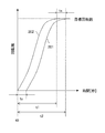
- FIG. 2 is a diagram illustrating an example of the sensorless motor from when the inverter receives a start signal from the start control processing unit 20 until the target rotational speed is reached.
- the vertical axis shows the number of rotations of the rotor, and the horizontal axis shows time.
- a curve 201 indicates a change in the rotation speed (change in the conventional rotation speed) when the first process is executed on the electric motor 10 after the inverter 11 receives the start signal (t0).
- a curve 202 is a case where the electric supercharger 4 is present, and a change in the rotational speed when the first process is executed on the electric motor 10 before the inverter 11 receives the start signal (t0) (using the control of the invention). Change in the number of revolutions).
- phase detection time (ts) is a short time, but is a useless time that does not contribute to the time (t2) from the time (t0) until the rotation of the rotor reaches the target rotational speed. Further, the ratio of the phase detection time (ts) to the time (t2) is large.
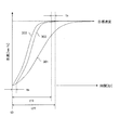
- FIG. 3 is a diagram illustrating an example of a vehicle including an electric supercharger having a sensorless electric motor until the vehicle reaches a target speed after receiving the activation signal from the activation control processing unit 20.
- the vertical axis represents the vehicle speed
- the horizontal axis represents time.
- a curve 301 shows a change in vehicle speed when there is no electric supercharger (change in vehicle speed when only an internal combustion engine is used).
- a curve 302 shows a case where the electric supercharger 4 is present, and a change in vehicle speed (conventional internal combustion engine + electric supercharger) when the first process is executed on the electric motor 10 after the inverter 11 receives the start signal (t0). Change in vehicle speed).
- a curve 303 shows a case where the electric supercharger 4 is present, and changes in vehicle speed when the first process is executed on the electric motor 10 before the inverter 11 receives the start signal (t0) (internal combustion using the control of the invention). (Change in vehicle speed of engine + electric supercharger).
- the first process is performed before the start signal shown in FIG. 3 is received (t0), so that the rotor is moved after the start signal is received (t0).
- the vehicle speed can be made the target speed faster than the conventional control.
- control unit 5 determines whether or not the rotational speed of the rotor is equal to or lower than the predetermined rotational speed Nth by using the rotational speed of the rotor monitored by the inverter 11.
- the inverter 11 is made to perform the first process.
- the inverter 11 monitors the induced voltage of the electric motor 10 to estimate the phase of the rotor
- the induced voltage is proportional to the rotation speed, and therefore the rotation of the rotor is a predetermined value indicating the detection limit of the induced voltage.
- the rotational speed is less than Nth, phase estimation cannot be performed.
- the inverter 11 rotates the rotor of the electric motor 10 after being delayed by the phase detection time (ts).
- the first process is forcibly performed when the rotation speed becomes equal to or lower than the predetermined rotation speed Nth, thereby shortening the time from when the start signal is received (t0) until the rotor reaches the target rotation speed.
- the predetermined rotational speed is, for example, a rotational speed indicating a detection limit of the induced voltage.
- the first processing is forcibly performed when the rotation of the rotor becomes equal to or lower than the predetermined rotation speed Nth, and the activation signal is sent from the activation control processing unit 20 to the inverter when the accelerator is depressed.
- the first process is terminated before being transmitted to 11, thereby shortening the time from when the start signal is received (t0) until the rotor reaches the target rotational speed.
- the rotation of the rotor of the electric motor 10 of the vehicle becomes equal to or less than the predetermined rotation speed Nth indicating the detection limit of the induced voltage, the phase cannot be estimated.
- the inverter 11 is connected to the rotor of the electric motor 10 after being delayed by the phase detection time (ts) as in the prior art. Will start. Then, acceleration to the target speed of the vehicle is delayed by the phase detection time (ts). Accordingly, the first process is forcibly performed when the rotation speed is equal to or lower than the predetermined rotation speed Nth, thereby shortening the time from when the start signal is received (t0) until the vehicle reaches the target speed.
- the second processing unit will be described.
- the second processing unit 19 performs the initial phase alignment and holds the rotor magnetic poles at the initial phase aligned position (predetermined position) with respect to the stator of the electric motor 10 until the start signal is received.
- the holding current is output to the inverter 11. That is, by constantly applying a minute current for maintaining the phase, the phase shift of the rotor due to intake air or disturbance is suppressed.
- the second processing unit 19 functions as a phase holding unit. (5) The second processing unit 19 executes the initial phase alignment (first processing) of the rotor by the first processing unit 18 and receives the activation signal from the activation control processing unit 20 (A) (B) causes the inverter 11 to output a holding current for holding the magnetic poles of the rotor at a predetermined position so that the rotor does not rotate. This holding current suppresses the rotor phase shift due to (A), (B), and the like.
- FIG. 4 is a diagram for explaining the first process and the second process.
- the horizontal axis from A to C in FIG. 4 represents time, and the vertical axis from A in FIG. 4 represents the shaft rotational speed (or may be the rotational speed).
- the vertical axis of B in FIG. 4 indicates the holding current (excitation current), and the vertical axis of C in FIG. 4 indicates the flow rate.
- the first process is executed to the stator.
- the magnetic pole of the rotor is adjusted to a predetermined position (period from T1 to T2).
- the second process is executed to cause the inverter 11 to output a holding current Ih (solid line) for holding the rotor magnetic poles at a predetermined position (period T2 to T5).
- the holding current Ih is an excitation current determined in advance so that the position of the rotor does not shift due to (A), (B), or the like, through experiments or simulations.
- the inverter 11 receives the activation signal (T5), the activation control process is activated.
- the second processing unit 19 executes the process described in (5), the phase shift of the rotor due to (A) and (B) can be suppressed, but the holding current until the start signal is received. It is necessary to flow Ih (solid line). Therefore, in order to reduce the power consumption due to the holding current, control is performed to increase or decrease the holding current according to the amount of air sucked into the electric supercharger 4 of the vehicle.
- the flow of air sucked into the impeller of the compressor 9 connected to the rotor (A) is monitored using the flow meter 21 or the like, and the holding current is determined according to the intake air flow rate measured by the flow meter 21.
- the holding current is determined by referring to information relating the intake air flow rate and the holding current created in advance by experiment or simulation.
- the installation position of the flow meter 21 is not limited to the position shown in FIG.
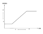
- FIG. 5 is a diagram showing the relationship between the flow rate and the holding current. Information that associates the intake air flow rate with the holding current is created based on the graph shown in FIG. The vertical axis in FIG. 5 indicates the holding current, and the horizontal axis indicates the flow rate. If the flow rate is increased, the holding current is increased, and if the flow rate is decreased, the holding current is decreased.
- the flow rate decreases in the period from T0 to T3. 4A and 4B, the first process is completed at T2. Therefore, the holding current Ih is increased or decreased with reference to the information created based on FIG. 5 until the activation signal is received (period T2 to T5). That is, by controlling the holding current 201 (broken line) shown in FIG. 4B, a constant holding current Ih (solid line) flows in the process of (5), but in the process of (6), it depends on the amount of intake air. Since the holding current can be increased or decreased, power consumption can be reduced.
- FIG. 6 is a flowchart showing an embodiment of the operation of the control unit.
- step S2 When the control unit 5 detects that the ignition switch of the vehicle is turned on in step S1 (I / G on), in step S2, the control unit 5 supplies power from the second battery 12 to the inverter 11, and the inverter 11 is turned on (inverter on). When the processes of steps S1 and S2 are completed, the stopped vehicle is ready to travel.
- step S ⁇ b> 3 the control unit 5 causes the inverter 11 to perform control (first processing) for initial phase alignment of the magnetic poles of the rotor with respect to the stator of the electric motor 10.
- control first processing
- the electric motor 10 is a synchronous motor
- electric power is supplied to the windings of the stator so that the magnetic poles of the rotor are aligned with predetermined positions.
- the phase detection method is not limited to this method.
- the second process is executed. In the second process, after the control unit 5 performs the first process, the rotor magnetic poles are held at a position (predetermined position) in which the rotor magnetic poles are initially phased with respect to the stator of the electric motor 10 until the start signal is received. The holding current is output to the inverter 11.
- step S4 when the control unit 5 detects the activation signal (Yes), the process proceeds to step S5.
- the control unit 5 waits to detect the activation signal in step S4. .
- the activation control processing unit 20 of the control unit 5 detects that the activation signal is greater than a predetermined depression amount. Then, the signal is transmitted to the inverter 11.
- step S5 when a start signal is detected in step S4, the control unit 5 transmits to the inverter 11 a command having information for setting the rotor of the electric motor 10 to the target rotational speed.
- the inverter 11 that has received the command activates the electric motor 10 and causes the rotation of the rotor to reach the target rotational speed.
- step S6 when the control unit 5 detects a stop signal (Yes), the process proceeds to step S7.
- the control unit 5 waits for detection of the stop signal in step S6.
- the stop signal is, for example, a signal for stopping the electric supercharger 4 when the rotor of the electric motor 10 reaches the target rotation speed and the supercharger 3 starts to work.
- step S7 the control unit 5 stops the power supply from the inverter 11 to the electric motor 10. Even if the power supply is stopped in step S7, the rotation of the rotor of the electric motor 10 does not stop immediately due to inertia but continues to rotate (free run).
- step S8 the control unit 5 determines whether or not phase estimation is possible. If phase estimation is possible (Yes), the process proceeds to step S9. If phase estimation is not possible (No), the process proceeds to step S3. Transition.
- step S9 when a start signal is received in a state where the phase can be estimated (Yes), the process proceeds to step S5, and the start control processing unit 20 of the control unit 5 instructs the inverter 11 to start the electric motor 10.
- the process proceeds to step S8.
- Steps S7 to S9 when the rotation of the rotor reaches the target rotational speed after receiving the start signal and rotating the rotor of the electric motor 10, the supply of electric power from the inverter 11 to the electric motor 10 is stopped. However, the rotation of the rotor does not stop immediately due to inertia (free run). However, phase estimation becomes impossible when the rotational speed of the rotor falls below a predetermined rotational speed during free run. For example, when the inverter 11 monitors the induced voltage of the electric motor 10 and estimates the phase of the rotor, the induced voltage is proportional to the rotation speed, so the rotation of the rotor indicates the detection limit of the induced voltage. If the number is less than the number, phase estimation cannot be performed.
- the inverter 11 rotates the rotor of the electric motor 10 after being delayed by the phase detection time (ts). Therefore, the time from when the start signal is received (t0) to when the rotor reaches the target rotational speed is shortened by forcibly detecting the phase when the rotational speed is less than the predetermined rotational speed Nth.
- the above-described control may be a sensorless electric motor, and can be applied to an electric motor used to reach the target rotational speed in a short time.
Landscapes
- Engineering & Computer Science (AREA)
- Power Engineering (AREA)
- Mechanical Engineering (AREA)
- Transportation (AREA)
- Chemical & Material Sciences (AREA)
- General Engineering & Computer Science (AREA)
- Combustion & Propulsion (AREA)
- Life Sciences & Earth Sciences (AREA)
- Sustainable Development (AREA)
- Sustainable Energy (AREA)
- Computer Hardware Design (AREA)
- Microelectronics & Electronic Packaging (AREA)
- Supercharger (AREA)
- Control Of Motors That Do Not Use Commutators (AREA)
Abstract
Description
(1)センサレスの電動機10を起動させる場合には第一の処理を行う必要がある。従来のように起動信号を受信(t0)してから第一の処理を開始し終了する場合には、曲線201に示すように、起動信号を受信した時間(t0)から第一の処理を終了するまでの位相検出時間(ts)が必要である。この位相検出時間(ts)は僅かな時間ではあるが、時間(t0)からロータの回転が目標回転数に達するまでの時間(t2)に寄与しない無駄な時間である。また、位相検出時間(ts)の時間(t2)を占める割合は大きい。そこで、上記のようにインバータ11が起動信号を受信(t0)する前に第一の処理をすることで、起動信号を受信(t0)してからロータが目標回転数に達するまでの時間(t1)を短縮させる(t1=t2-ts)。曲線202を参照。
(2)車両の電動過給機4の場合には、図3に示す起動信号を受信(t0)する前に第一の処理をすることで、起動信号を受信(t0)してからロータが目標回転数に達するまでの時間(t11)を短縮させることで(t11=t22-ts)、従来の制御より早く車両の速度を目標速度にすることができる。従来の車両の電動過給機4の場合、アクセルを踏み込むことにより、起動信号がインバータ11に送信され、インバータ11が起動信号を受信(t0)すると第一の処理をし、車両の電動機10のロータが回転を開始し、圧縮機9から内燃機関2への過給が開始される。そして、車両が目標速度になると電動機10への電力の供給が停止される。曲線302を参照。このように、従来の車両の電動機10においても、位相検出時間(ts)は目標速度への加速に寄与しない無駄な時間である。そこで、アクセルの踏み込みにより起動信号が送信され、インバータ11が受信(t0)する前に、第一の処理を終了させておくことで、加速に寄与しない無駄な時間をなくすことができる(t11=t22-ts)。曲線303を参照。
(3)起動信号を受信して電動機10のロータが回転した後、ロータの回転が目標回転数に達すると、インバータ11から電動機10への電力の供給が停止される。ところが、ロータの回転は慣性によりすぐには停止せず、回転は継続する(フリーラン)。しかし、フリーラン中にロータの回転数が所定回転数Nth以下になると位相推定ができなくなる。例えば、インバータ11が電動機10の誘起電圧をモニタリングしてロータの位相推定をしている場合には、誘起電圧は回転数に比例しているため、ロータの回転が誘起電圧の検出限界を示す所定回転数Nth以下になると位相推定ができなくなる。この時に、従来のように新たに起動信号を受信してから第一の処理を行うと、位相検出時間(ts)だけ遅れてから、インバータ11が電動機10のロータを回転させることになる。そこで、所定回転数Nth以下になると強制的に第一の処理をさせることで、起動信号を受信(t0)してからロータが目標回転数に達するまでの時間を短縮させる。所定回転数は、例えば、誘起電圧の検出限界を示す回転数である。
(4)車両の電動過給機4の場合にも、ロータの回転が所定回転数Nth以下になると強制的に第一の処理をさせ、アクセルの踏み込みにより起動信号が起動制御処理部20からインバータ11に送信される前に、第一の処理を終了させることで、起動信号を受信(t0)してからロータが目標回転数に達するまでの時間を短縮させる。車両の電動機10のロータの回転が誘起電圧の検出限界を示す所定回転数Nth以下になると位相推定ができなくなる。この時に、アクセルが踏み込まれ、新たに起動信号を受信(t0)してから第一の処理を行うと、従来のように位相検出時間(ts)だけ遅れてから、インバータ11は電動機10のロータを起動することになる。そうすると、位相検出時間(ts)により車両の目標速度への加速が遅れる。そこで、所定回転数Nth以下になると強制的に第一の処理をさせることで、起動信号を受信(t0)してから車両が目標速度に達するまでの時間を短縮させる。
(5)第二の処理部19は、第一の処理部18によりロータの初期位相合わせ(第一の処理)が実行され、起動制御処理部20からの起動信号を受信するまで、(A)(B)などによりロータが回転しないように、ロータの磁極を所定位置に保持するための保持電流をインバータ11に出力させる。この保持電流により、(A)(B)などによるロータの位相ずれを抑制する。
(6)第二の処理部19が(5)で説明した処理を実行することで、(A)(B)によるロータの位相ずれを抑制することができるが、起動信号を受信するまで保持電流Ih(実線)を流す必要がある。そこで、保持電流による消費電力を低減するため、車両の電動過給機4に吸入される空気量によって保持電流を増減する制御をする。すなわち、上記(A)ロータに接続されている圧縮機9のインペラに吸入される空気の流れ込みを、流量計21などを用いてモニタリングし、流量計21の計測した吸入空気流量に応じて保持電流を変化させる。例えば、計測した吸入空気流量を用いて、実験またはシミュレーションにより予め作成した吸入空気流量と保持電流とを関連付けた情報を参照し、保持電流を決定する。なお、流量計21の設置位置は図1に示す位置に限定されるものではない。
2 内燃機関、
3 過給機、
4 電動過給機、
5 制御部、
6 オルタネータ、
7 第一の電池、
8 DC/DCコンバータ、
9 圧縮機、
10 電動機、
11 インバータ、
12 第二の電池、
14 出力軸、
15 駆動輪、
16、17 配管、
18 第一の処理部、
19 第二の処理部、
20 起動制御処理部、
21 流量計、 22 バルブ、
Claims (5)
- センサレスの電動機を駆動させるインバータと、
前記電動機を起動させる起動信号を前記インバータが受信する前に、前記電動機のステータに対してロータの磁極を所定位置にする位相検出を、前記インバータにさせる位相検出部と、
を備えることを特徴とする電動機の制御装置。 - 請求項1に記載の制御装置であって、
前記位相検出部は、
前記起動信号を受信して前記ロータが回転した後、前記ロータの回転数が所定回転数以下になると、前記位相検出を前記インバータにさせる、
ことを特徴とする電動機の制御装置。 - 請求項1または2に記載の電動機の制御装置であって、
前記位相検出後に、前記起動信号を受信するまで前記所定位置を保持するための保持電流を前記インバータに出力させる位相保持部と、を備える、
ことを特徴とする電動機の制御装置。 - 請求項3に記載の電動機の制御装置であって、
前記位相保持部は、
計測した吸入空気量に応じて、前記保持電流を増減させて前記インバータに出力させる、
ことを特徴とする電動機の制御装置。 - 請求項1~4のいずれか一項に記載の電動機の制御装置であって、
前記制御装置は、
電動過給機に設けられる前記インバータおよび前記電動機を制御する、
ことを特徴とする電動機の制御装置。
Priority Applications (3)
| Application Number | Priority Date | Filing Date | Title |
|---|---|---|---|
| EP15768361.6A EP3125423A4 (en) | 2014-03-28 | 2015-02-13 | Electric motor control device |
| JP2016510113A JP6160768B2 (ja) | 2014-03-28 | 2015-02-13 | 電動機の制御装置 |
| US15/129,688 US9973122B2 (en) | 2014-03-28 | 2015-02-13 | Electric motor control device |
Applications Claiming Priority (4)
| Application Number | Priority Date | Filing Date | Title |
|---|---|---|---|
| JP2014068849 | 2014-03-28 | ||
| JP2014-068849 | 2014-03-28 | ||
| JP2014182869 | 2014-09-09 | ||
| JP2014-182869 | 2014-09-09 |
Publications (1)
| Publication Number | Publication Date |
|---|---|
| WO2015146350A1 true WO2015146350A1 (ja) | 2015-10-01 |
Family
ID=54194888
Family Applications (1)
| Application Number | Title | Priority Date | Filing Date |
|---|---|---|---|
| PCT/JP2015/053973 Ceased WO2015146350A1 (ja) | 2014-03-28 | 2015-02-13 | 電動機の制御装置 |
Country Status (4)
| Country | Link |
|---|---|
| US (1) | US9973122B2 (ja) |
| EP (1) | EP3125423A4 (ja) |
| JP (1) | JP6160768B2 (ja) |
| WO (1) | WO2015146350A1 (ja) |
Families Citing this family (2)
| Publication number | Priority date | Publication date | Assignee | Title |
|---|---|---|---|---|
| JP6269330B2 (ja) * | 2014-06-06 | 2018-01-31 | トヨタ自動車株式会社 | 内燃機関の制御装置 |
| KR102516569B1 (ko) * | 2017-11-03 | 2023-04-03 | 현대자동차주식회사 | 차량 및 그 제어방법 |
Citations (8)
| Publication number | Priority date | Publication date | Assignee | Title |
|---|---|---|---|---|
| JPH04275093A (ja) * | 1991-02-28 | 1992-09-30 | Sony Corp | ブラシレスモータ駆動回路 |
| JPH0787785A (ja) * | 1993-06-29 | 1995-03-31 | Fujitsu General Ltd | ブラシレスモータの制御方法およびその装置 |
| JPH08266088A (ja) * | 1995-03-27 | 1996-10-11 | Nippondenso Co Ltd | 電動機用制御装置 |
| JPH11318096A (ja) * | 1998-04-30 | 1999-11-16 | Seiko Seiki Co Ltd | ブラシレスモータの駆動装置 |
| JP2004242422A (ja) * | 2003-02-06 | 2004-08-26 | Toyota Motor Corp | 電動機の回転駆動制御装置 |
| US20110227519A1 (en) * | 2010-03-17 | 2011-09-22 | Alex Horng | Sensorless starting control method for a bldc motor |
| JP2012249355A (ja) * | 2011-05-25 | 2012-12-13 | Hitachi Appliances Inc | モータ制御装置、及び、それを利用したモータの起動方法 |
| JP2014036536A (ja) * | 2012-08-10 | 2014-02-24 | Hitachi Automotive Systems Ltd | モータ部およびインバータ部を備えたモータ制御装置 |
Family Cites Families (5)
| Publication number | Priority date | Publication date | Assignee | Title |
|---|---|---|---|---|
| JP2006271179A (ja) * | 2005-02-23 | 2006-10-05 | Mitsubishi Heavy Ind Ltd | モータ制御装置およびモータ制御方法 |
| JP4735427B2 (ja) | 2005-10-07 | 2011-07-27 | トヨタ自動車株式会社 | 内燃機関の制御装置 |
| US7723931B2 (en) | 2006-05-31 | 2010-05-25 | Pratt & Whitney Canada Corp. | Starting a gas turbine engine using a sensorless, brushless motor |
| US7786687B2 (en) * | 2008-04-25 | 2010-08-31 | Gm Global Technology Operations, Inc. | Apparatus and method for control of an active front steering (AFS) system |
| JP5724977B2 (ja) | 2012-09-20 | 2015-05-27 | 株式会社デンソー | ブラシレスモータの制御システム |
-
2015
- 2015-02-13 JP JP2016510113A patent/JP6160768B2/ja not_active Expired - Fee Related
- 2015-02-13 US US15/129,688 patent/US9973122B2/en active Active
- 2015-02-13 WO PCT/JP2015/053973 patent/WO2015146350A1/ja not_active Ceased
- 2015-02-13 EP EP15768361.6A patent/EP3125423A4/en not_active Withdrawn
Patent Citations (8)
| Publication number | Priority date | Publication date | Assignee | Title |
|---|---|---|---|---|
| JPH04275093A (ja) * | 1991-02-28 | 1992-09-30 | Sony Corp | ブラシレスモータ駆動回路 |
| JPH0787785A (ja) * | 1993-06-29 | 1995-03-31 | Fujitsu General Ltd | ブラシレスモータの制御方法およびその装置 |
| JPH08266088A (ja) * | 1995-03-27 | 1996-10-11 | Nippondenso Co Ltd | 電動機用制御装置 |
| JPH11318096A (ja) * | 1998-04-30 | 1999-11-16 | Seiko Seiki Co Ltd | ブラシレスモータの駆動装置 |
| JP2004242422A (ja) * | 2003-02-06 | 2004-08-26 | Toyota Motor Corp | 電動機の回転駆動制御装置 |
| US20110227519A1 (en) * | 2010-03-17 | 2011-09-22 | Alex Horng | Sensorless starting control method for a bldc motor |
| JP2012249355A (ja) * | 2011-05-25 | 2012-12-13 | Hitachi Appliances Inc | モータ制御装置、及び、それを利用したモータの起動方法 |
| JP2014036536A (ja) * | 2012-08-10 | 2014-02-24 | Hitachi Automotive Systems Ltd | モータ部およびインバータ部を備えたモータ制御装置 |
Non-Patent Citations (1)
| Title |
|---|
| See also references of EP3125423A4 * |
Also Published As
| Publication number | Publication date |
|---|---|
| US20170133963A1 (en) | 2017-05-11 |
| JPWO2015146350A1 (ja) | 2017-04-13 |
| EP3125423A4 (en) | 2017-11-29 |
| EP3125423A1 (en) | 2017-02-01 |
| JP6160768B2 (ja) | 2017-07-12 |
| US9973122B2 (en) | 2018-05-15 |
Similar Documents
| Publication | Publication Date | Title |
|---|---|---|
| US8292778B2 (en) | Idle-stop restart control system | |
| JP5843915B2 (ja) | 車両の制御装置 | |
| JPWO2014174567A1 (ja) | エンジン停止制御装置およびエンジン停止制御方法 | |
| CN102859181B (zh) | 驱动控制装置、驱动控制系统及驱动控制方法 | |
| CN104819085A (zh) | 评估用于内燃发动机的起动机电动机的方法和装置 | |
| KR101637821B1 (ko) | 하이브리드 차량의 엔진 정지 제어장치 및 방법 | |
| CN106536917B (zh) | 用于起动内燃机的方法 | |
| US10190561B1 (en) | System and method for rapid engine start | |
| CN103684142B (zh) | 用于无刷电机的控制系统 | |
| JP6160768B2 (ja) | 電動機の制御装置 | |
| CN103597200B (zh) | 车辆用起动装置 | |
| JP2014207731A (ja) | ブラシレスモータの制御装置 | |
| CN114483336B (zh) | 发动机转动控制方法、装置、摩托车和存储介质 | |
| US10351142B2 (en) | Hybrid vehicle | |
| WO2013171843A1 (ja) | 界磁巻線式回転電機および界磁巻線式回転電機の界磁電流制御方法 | |
| CN114993366A (zh) | 用于位置传感器零点自动校准方法、装置和设备 | |
| JP6651975B2 (ja) | 制御システム | |
| JP6515786B2 (ja) | エンジンの始動制御装置 | |
| JP6659596B2 (ja) | 特に自動車両の熱機関を始動させる或いは再始動させるための方法及び装置 | |
| JP5003233B2 (ja) | ハイブリッド車両の制御装置 | |
| US20120261916A1 (en) | Power-generation motor control system | |
| JP6319021B2 (ja) | 電動過給機の制御装置 | |
| CN112311288B (zh) | 一种电机位置传感器校验方法、装置、设备及存储介质 | |
| JP5853707B2 (ja) | 充電装置 | |
| JP2015101299A (ja) | エンジン制御装置 |
Legal Events
| Date | Code | Title | Description |
|---|---|---|---|
| 121 | Ep: the epo has been informed by wipo that ep was designated in this application |
Ref document number: 15768361 Country of ref document: EP Kind code of ref document: A1 |
|
| ENP | Entry into the national phase |
Ref document number: 2016510113 Country of ref document: JP Kind code of ref document: A |
|
| WWE | Wipo information: entry into national phase |
Ref document number: 15129688 Country of ref document: US |
|
| NENP | Non-entry into the national phase |
Ref country code: DE |
|
| REEP | Request for entry into the european phase |
Ref document number: 2015768361 Country of ref document: EP |
|
| WWE | Wipo information: entry into national phase |
Ref document number: 2015768361 Country of ref document: EP |