WO2015146660A1 - 鞍乗型車両 - Google Patents
鞍乗型車両 Download PDFInfo
- Publication number
- WO2015146660A1 WO2015146660A1 PCT/JP2015/057635 JP2015057635W WO2015146660A1 WO 2015146660 A1 WO2015146660 A1 WO 2015146660A1 JP 2015057635 W JP2015057635 W JP 2015057635W WO 2015146660 A1 WO2015146660 A1 WO 2015146660A1
- Authority
- WO
- WIPO (PCT)
- Prior art keywords
- link mechanism
- lock
- vehicle
- state
- notification
- Prior art date
- Legal status (The legal status is an assumption and is not a legal conclusion. Google has not performed a legal analysis and makes no representation as to the accuracy of the status listed.)
- Ceased
Links
Images


Classifications
-
- B—PERFORMING OPERATIONS; TRANSPORTING
- B62—LAND VEHICLES FOR TRAVELLING OTHERWISE THAN ON RAILS
- B62J—CYCLE SADDLES OR SEATS; AUXILIARY DEVICES OR ACCESSORIES SPECIALLY ADAPTED TO CYCLES AND NOT OTHERWISE PROVIDED FOR, e.g. ARTICLE CARRIERS OR CYCLE PROTECTORS
- B62J50/00—Arrangements specially adapted for use on cycles not provided for in main groups B62J1/00 - B62J45/00
- B62J50/20—Information-providing devices
- B62J50/21—Information-providing devices intended to provide information to rider or passenger
-
- B—PERFORMING OPERATIONS; TRANSPORTING
- B62—LAND VEHICLES FOR TRAVELLING OTHERWISE THAN ON RAILS
- B62K—CYCLES; CYCLE FRAMES; CYCLE STEERING DEVICES; RIDER-OPERATED TERMINAL CONTROLS SPECIALLY ADAPTED FOR CYCLES; CYCLE AXLE SUSPENSIONS; CYCLE SIDE-CARS, FORECARS, OR THE LIKE
- B62K23/00—Rider-operated controls specially adapted for cycles, i.e. means for initiating control operations, e.g. levers, grips
- B62K23/02—Rider-operated controls specially adapted for cycles, i.e. means for initiating control operations, e.g. levers, grips hand actuated
-
- B—PERFORMING OPERATIONS; TRANSPORTING
- B62—LAND VEHICLES FOR TRAVELLING OTHERWISE THAN ON RAILS
- B62K—CYCLES; CYCLE FRAMES; CYCLE STEERING DEVICES; RIDER-OPERATED TERMINAL CONTROLS SPECIALLY ADAPTED FOR CYCLES; CYCLE AXLE SUSPENSIONS; CYCLE SIDE-CARS, FORECARS, OR THE LIKE
- B62K5/00—Cycles with handlebars, equipped with three or more main road wheels
- B62K5/02—Tricycles
- B62K5/027—Motorcycles with three wheels
-
- B—PERFORMING OPERATIONS; TRANSPORTING
- B62—LAND VEHICLES FOR TRAVELLING OTHERWISE THAN ON RAILS
- B62K—CYCLES; CYCLE FRAMES; CYCLE STEERING DEVICES; RIDER-OPERATED TERMINAL CONTROLS SPECIALLY ADAPTED FOR CYCLES; CYCLE AXLE SUSPENSIONS; CYCLE SIDE-CARS, FORECARS, OR THE LIKE
- B62K5/00—Cycles with handlebars, equipped with three or more main road wheels
- B62K5/02—Tricycles
- B62K5/05—Tricycles characterised by a single rear wheel
-
- B—PERFORMING OPERATIONS; TRANSPORTING
- B62—LAND VEHICLES FOR TRAVELLING OTHERWISE THAN ON RAILS
- B62K—CYCLES; CYCLE FRAMES; CYCLE STEERING DEVICES; RIDER-OPERATED TERMINAL CONTROLS SPECIALLY ADAPTED FOR CYCLES; CYCLE AXLE SUSPENSIONS; CYCLE SIDE-CARS, FORECARS, OR THE LIKE
- B62K5/00—Cycles with handlebars, equipped with three or more main road wheels
- B62K5/08—Cycles with handlebars, equipped with three or more main road wheels with steering devices acting on two or more wheels
-
- B—PERFORMING OPERATIONS; TRANSPORTING
- B62—LAND VEHICLES FOR TRAVELLING OTHERWISE THAN ON RAILS
- B62K—CYCLES; CYCLE FRAMES; CYCLE STEERING DEVICES; RIDER-OPERATED TERMINAL CONTROLS SPECIALLY ADAPTED FOR CYCLES; CYCLE AXLE SUSPENSIONS; CYCLE SIDE-CARS, FORECARS, OR THE LIKE
- B62K5/00—Cycles with handlebars, equipped with three or more main road wheels
- B62K5/10—Cycles with handlebars, equipped with three or more main road wheels with means for inwardly inclining the vehicle body on bends
-
- B—PERFORMING OPERATIONS; TRANSPORTING
- B62—LAND VEHICLES FOR TRAVELLING OTHERWISE THAN ON RAILS
- B62J—CYCLE SADDLES OR SEATS; AUXILIARY DEVICES OR ACCESSORIES SPECIALLY ADAPTED TO CYCLES AND NOT OTHERWISE PROVIDED FOR, e.g. ARTICLE CARRIERS OR CYCLE PROTECTORS
- B62J45/00—Electrical equipment arrangements specially adapted for use as accessories on cycles, not otherwise provided for
- B62J45/40—Sensor arrangements; Mounting thereof
-
- B—PERFORMING OPERATIONS; TRANSPORTING
- B62—LAND VEHICLES FOR TRAVELLING OTHERWISE THAN ON RAILS
- B62K—CYCLES; CYCLE FRAMES; CYCLE STEERING DEVICES; RIDER-OPERATED TERMINAL CONTROLS SPECIALLY ADAPTED FOR CYCLES; CYCLE AXLE SUSPENSIONS; CYCLE SIDE-CARS, FORECARS, OR THE LIKE
- B62K5/00—Cycles with handlebars, equipped with three or more main road wheels
- B62K2005/001—Suspension details for cycles with three or more main road wheels
-
- B—PERFORMING OPERATIONS; TRANSPORTING
- B62—LAND VEHICLES FOR TRAVELLING OTHERWISE THAN ON RAILS
- B62K—CYCLES; CYCLE FRAMES; CYCLE STEERING DEVICES; RIDER-OPERATED TERMINAL CONTROLS SPECIALLY ADAPTED FOR CYCLES; CYCLE AXLE SUSPENSIONS; CYCLE SIDE-CARS, FORECARS, OR THE LIKE
- B62K25/00—Axle suspensions
- B62K25/04—Axle suspensions for mounting axles resiliently on cycle frame or fork
- B62K2025/047—Axle suspensions for mounting axles resiliently on cycle frame or fork with suspension locking means
Definitions
- the present invention relates to a straddle-type vehicle, and more particularly to a straddle-type vehicle including a pair of front wheels.
- the straddle-type vehicle includes, for example, a three-wheeled vehicle including a pair of front wheels and a link mechanism that connects the pair of front wheels to a vehicle body frame.
- a three-wheeled vehicle including a pair of front wheels and a link mechanism that connects the pair of front wheels to a vehicle body frame.
- the vehicle can be tilted and turned by the operation of the link mechanism.
- JP-A-2005-313876 discloses an anti-roll device for a three-wheeled vehicle.
- the anti-roll device includes a brake disk provided integrally with one element of the link mechanism, and a caliper attached to the vehicle body frame.
- the brake disc is fixed to the vehicle body frame by a caliper. Thereby, operation
- movement of a link mechanism can be controlled. As a result, the rolling motion of the vehicle can be prevented.
- the vehicle maneuverability differs greatly between the state where the operation of the link mechanism is restricted and the state where it is not restricted. Therefore, the occupant often operates the vehicle after recognizing whether or not the operation of the link mechanism is restricted. At this time, in some cases, a difference may occur between the actual state of the link mechanism and the occupant's perception of the state of the link mechanism.
- An object of the present invention is to provide a straddle-type vehicle in which a deviation is less likely to occur between an actual link mechanism state and an occupant's recognition of the link mechanism state.
- the straddle-type vehicle includes a body frame, a pair of front wheels, a link mechanism, a lock mechanism, a control unit, and a notification unit.
- the link mechanism connects the pair of front wheels to the vehicle body frame.
- the lock mechanism places the link mechanism in a locked state by restricting the operation of the link mechanism, and places the link mechanism in an unlocked state by allowing the operation of the link mechanism.
- the control unit controls locking and unlocking of the link mechanism by the lock mechanism.
- the notification unit notifies that the vehicle is running in a state where the lock mechanism locks the link mechanism.
- a straddle-type vehicle according to a second aspect of the present invention is the straddle-type vehicle according to the first aspect, wherein the notification unit is configured such that the vehicle is at a predetermined vehicle speed or higher in a state where the lock mechanism locks the link mechanism. Inform you that you are traveling. In this case, it can be appropriately notified that the link mechanism is in the locked state.
- a straddle-type vehicle according to a third aspect of the present invention is the straddle-type vehicle according to the first or second aspect, wherein the notification unit is configured so that the vehicle is in a predetermined time in a state where the lock mechanism locks the link mechanism. Notify that you are traveling. In this case, it can be appropriately notified that the link mechanism is in the locked state.
- a straddle-type vehicle according to a fourth aspect of the present invention is the straddle-type vehicle according to the first aspect, wherein the notifying unit locks the link mechanism after the lock mechanism is locked.
- the lock mechanism is notified that the link mechanism is locked. In this case, it can be appropriately notified that the link mechanism is in the locked state.
- a straddle-type vehicle is the straddle-type vehicle according to the first aspect, further comprising a notification condition determination unit and a notification control unit.
- the notification condition determination unit determines whether a notification condition for notifying the lock state of the link mechanism is satisfied based on at least one of the vehicle speed and the travel time in a state where the lock mechanism locks the link mechanism.
- the notification control unit controls the notification unit and notifies the lock state of the link mechanism. In this case, it can be appropriately notified that the link mechanism is in the locked state.
- a straddle-type vehicle according to a sixth aspect of the present invention is the straddle-type vehicle according to any one of the first to fifth aspects, further comprising a damper.
- the damper dampens antiphase vibrations that occur in the pair of front wheels.
- the lock mechanism places the link mechanism in a locked state by restricting the operation of the damper, and places the link mechanism in an unlocked state by allowing the operation of the damper.
- a lock mechanism need not be provided separately. Therefore, a compact saddle riding type vehicle can be realized.
- FIG. 1 is a left side view showing a schematic configuration of a saddle riding type vehicle according to an embodiment of the present invention. It is a front view which shows schematic structure of a link mechanism. It is a figure which shows the hydraulic circuit of a damper. It is a block diagram for demonstrating the signal input into a control apparatus, and the signal output from a control apparatus. It is a flowchart which shows the lock control by a lock mechanism control part. It is a flowchart which shows alerting
- the saddle riding type vehicle includes a scooter type vehicle.
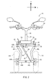
- FIG. 1 is a left side view showing a schematic configuration of a saddle riding type vehicle 10 according to an embodiment of the present invention.
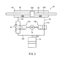
- FIG. 2 is a front view showing a schematic configuration of the link mechanism provided in the saddle riding type vehicle 10.
- front / rear / left / right means front / rear / left / right as viewed from the occupant seated on the seat 32 of the saddle riding type vehicle 10.
- the arrow F indicates the forward direction of the saddle riding type vehicle 10
- the arrow U indicates the upward direction of the saddle riding type vehicle 10.
- the arrow L indicates the left direction of the saddle riding type vehicle 10
- the arrow U indicates the upward direction of the saddle riding type vehicle 10.
- the saddle riding type vehicle 10 includes a body frame 12, a pair of front wheels 14L and 14R, and a rear wheel 16.
- the vehicle body frame 12 is covered with a vehicle cover 18 as shown in FIG.
- the vehicle body frame 12 includes a head pipe 20 as shown in FIG.
- the head pipe 20 is disposed at the front portion of the vehicle body frame 12 as shown in FIG. As shown in FIGS. 1 and 2, a steering shaft 26 is inserted into the head pipe 20. A handle 28 is disposed at the upper end of the steering shaft 26 as shown in FIGS.
- a front wheel support mechanism 30 is disposed in front of the head pipe 20 as shown in FIG. As shown in FIG. 2, the front wheel support mechanism 30 supports a pair of front wheels 14L and 14R. Details of the front wheel support mechanism 30 will be described later.
- the rear wheel 16 is disposed below the seat 32.
- the seat 32 is disposed above the body frame 12.
- the driving force of the engine 94 see FIG. 5
- the front wheel support mechanism 30 will be described with reference to FIG.
- the front wheel support mechanism 30 includes a link mechanism 36, a suspension 38 and a damper 40.
- the link mechanism 36 connects the pair of front wheels 14L and 14R to the vehicle body frame 12 (for example, a front frame disposed in front of the head pipe 20).
- the link mechanism 36 includes an upper left arm 42L, an upper right arm 42R, a lower left arm 44L, a lower right arm 44R, a left knuckle arm 46L, and a right knuckle arm 46R.
- One of the upper left arm 42L and the upper right arm 42R can swing around the swing center axis extending in the longitudinal direction of the vehicle relative to the other.
- the lower left arm 44L is disposed below the upper left arm 42L.
- the lower right arm 44R is disposed below the upper right arm 42R.
- One of the lower left arm 44L and the lower right arm 44R can swing around a swing center axis extending in the front-rear direction of the vehicle relative to the other.
- the left knuckle arm 46L extends in the vertical direction of the vehicle and connects the left end of the upper left arm 42L and the left end of the lower left arm 44L.
- the left knuckle arm 46L is disposed so as to be swingable about a swing center axis extending in the front-rear direction of the vehicle with respect to each of the upper left arm 42L and the lower left arm 44L. Therefore, the left knuckle arm 46L can move in the vertical direction.
- the right knuckle arm 46R extends in the vertical direction of the vehicle and connects the right end of the upper right arm 42R and the right end of the lower right arm 44R.
- the right knuckle arm 46R is disposed so as to be swingable about a swing center axis extending in the front-rear direction of the vehicle with respect to each of the upper right arm 42R and the lower right arm 44R. Therefore, the right knuckle arm 46R can move in the vertical direction.
- a front wheel support member 52L is disposed so as to be swingable about a swing center axis extending in the vertical direction of the vehicle.
- the front wheel support member 52L rotatably supports the front wheel 14L.
- a front wheel support member 52R is disposed so as to be swingable around a swing center axis extending in the vertical direction of the vehicle.
- the front wheel support member 52R rotatably supports the front wheel 14R.
- the front wheel support member 52L and the front wheel support member 52R rotate in plan view as the handle 28 is operated. Thereby, the saddle riding type vehicle 10 can turn left and right.
- the suspension 38 is disposed in the link mechanism 36.
- the suspension 38 includes a cylinder 54 and a piston 56.
- the cylinder 54 is attached to the right end portion of the upper right arm 42R via the bracket 60.
- the cylinder 54 is disposed so as to be swingable with respect to the upper right arm 42R.
- the cylinder 54 stores hydraulic oil.
- the piston 56 is attached to the left end portion of the upper left arm 42L via the bracket 58.
- the bracket 58 is fixed to the upper left arm 42L.
- the piston 56 is disposed so as to be swingable with respect to the bracket 58. Therefore, the piston 56 is disposed so as to be swingable with respect to the upper left arm 42L.
- the piston 56 is arranged so as to be movable in the axial direction of the cylinder 54.
- the piston 56 has a main body (not shown) disposed in the cylinder 54.
- a vibration that changes the relative position between the upper left arm 42L and the upper right arm 42R is input, the piston 56 moves in the axial direction of the cylinder 54 by moving back and forth in the cylinder 54.
- a damping force is obtained by the main body of the piston 56 moving in the cylinder 54.
- the vibration of displacement generated in the link mechanism 36 is attenuated.
- the vibrations with the same phase occur in the upper left arm 42L and the upper right arm 42R, that is, when vibrations with the same phase occur in the pair of front wheels 14L and 14R, the vibration is attenuated by the suspension 38.
- the damper 40 is disposed in the link mechanism 36.
- the damper 40 includes a piston 62 and a cylinder 64.
- the piston 62 is swingably attached to the lower left arm 44L.
- the cylinder 64 is swingably attached to the upper right arm 42R.
- FIG. 3 is a diagram illustrating a hydraulic circuit of the damper 40.
- the piston 62 includes a piston main body 62A and a piston rod 62B.
- the piston main body 62A is disposed at the axially central portion of the piston rod 62B.
- the piston main body 62 ⁇ / b> A is disposed so as to be movable in the cylinder 64.
- the piston rod 62B is disposed so as to penetrate the cylinder 64 in the axial direction. That is, the damper 40 is a so-called through rod type damper.
- the hydraulic oil is accommodated in the cylinder 64.
- the cylinder 64 is partitioned into two spaces (a first space 66A and a second space 66B) by the piston body 62A.
- the first space 66A and the second space 66B are connected to each other by an attenuation circuit 68. Therefore, the hydraulic oil can move between the first space 66A and the second space 66B via the attenuation circuit 68.
- the attenuation circuit 68 includes four flow paths 70A, 70B, 70C, and 70D, two flow rate adjustment units 72A and 72B, and one temperature compensation chamber 74.
- the flow rate adjustment unit 72A is connected to the first space 66A via the flow path 70A.
- the flow rate adjusting unit 72A is connected to the flow rate adjusting unit 72B via the flow path 70B.
- the flow rate adjustment unit 72B is connected to the second space 66B via the flow path 70C.
- the temperature compensation chamber 74 is connected to the flow path 70B via the flow path 70D.
- the flow path adjustment units 72A and 72B each include a switching valve 76. Each switching valve 76 is driven by an actuator 78.
- the actuator 78 is, for example, a motor.
- Each switching valve 76 includes a valve body and a spring.
- the valve body is disposed at a position where the flow path in the switching valve 76 is closed by the biasing force of the spring.
- hydraulic fluid is prevented from flowing through the damping circuit 66. That is, the operation of the damper 40 is restricted.
- the operation of the link mechanism 36 is restricted. That is, the link mechanism 36 is locked.
- Actuator 78 moves the valve body against the biasing force of the spring. At this time, the valve body is disposed at a position where the flow paths in the flow rate adjustment units 72A and 72B are not blocked. Therefore, the hydraulic oil is allowed to flow in the attenuation circuit 66. That is, the operation of the damper 40 is allowed. If the operation of the damper 40 is allowed, vibration can be damped. For example, when the antiphase vibration is generated in the lower left arm 44L and the upper right arm 42R, that is, when the antiphase vibration is generated in the pair of front wheels 14L and 14R, the vibration can be attenuated by the damper 40. When the operation of the damper 40 is allowed, the operation of the link mechanism 36 is allowed. That is, the link mechanism is unlocked.
- the lock mechanism 80 is realized including the damper 40, the attenuation circuit 66, and the actuator 78.
- the flow rate adjustment unit 72 ⁇ / b> A includes a relief valve 82.
- the relief valve 82 is arranged in parallel with the switching valve 76.
- the relief valve 82 prevents the internal pressure of the cylinder 64 from increasing when the operation of the damper 40 is restricted.
- FIG. 4 is a block diagram for explaining a signal input to the control device 84 and a signal output from the control device 84.
- the control device 84 includes a lock mechanism control unit 86 as a control unit and an engine control unit 88.
- the lock mechanism control unit 86 controls locking and unlocking of the link mechanism 36 by the lock mechanism 80.
- the lock mechanism control unit 86 includes a lock condition determination unit 86A, a signal input determination unit 86B, and a lock control unit 86C.
- the lock condition determination unit 86A determines whether or not a predetermined lock condition is satisfied based on the throttle opening signal D1, the vehicle speed signal D2, and the position signal D3. The lock condition will be described later.
- the throttle opening signal D1 is a signal output from the throttle opening detector 90 and indicates the throttle opening.
- the throttle opening signal D1 is input to the lock mechanism control unit 86 via the engine control unit 88.
- the vehicle speed signal D2 is a signal output from the vehicle speed detection unit 96 and indicates the vehicle speed.
- the vehicle speed detector 96 is, for example, a wheel speed sensor.
- the saddle riding type vehicle 10 includes an antilock brake system (ABS). Therefore, the vehicle speed signal D2 is input to the lock mechanism control unit 86 via the ABS control unit 98 that controls the operation of the ABS.
- ABS antilock brake system
- the position signal D3 is a signal output from the position detection unit 100, and indicates the position of the valve body included in the switching valve 76. That is, the position detection unit 100 detects whether or not the link mechanism 36 is in a locked state. When the valve body is in a position to close the flow path in the switching valve 76, the position detection unit 100 outputs a lock position signal as the position signal D3. When the valve body is in a position that does not block the flow path in the switching valve 76, the position detection unit 100 outputs a lock release position signal as the position signal D3.
- the position signal D3 is input to the lock mechanism control unit 86.
- the position detection unit 100 detects the position of the valve body by detecting, for example, the position of the valve body included in the switching valve 76, the position of the actuator 78, and the voltage at the time of driving the actuator 78.
- the signal input determination unit 86B determines whether the operation signal D4 is input in a state where the lock condition is satisfied. For this determination, the determination result of the lock condition determination unit 86A and the operation signal D4 input to the lock mechanism control unit 86 are used.
- the operation signal D4 is a signal output from the operation unit 104.
- the operation unit 104 continuously outputs the operation signal D4 to the lock mechanism control unit 86 when an operation by the occupant is performed.
- the operation signal D4 may be output continuously or intermittently.
- the operation unit 104 is disposed at a position where an operation by an occupant is possible.
- the operation unit 104 is realized by an operation switch disposed on the handle 28, for example.
- the lock control unit 86C controls the lock mechanism 80 and puts the link mechanism 36 into the lock state when the operation signal D4 is input in a state that satisfies the lock condition. Specifically, the lock control unit 86C drives the actuator 78 to move the valve body included in the switching valve 76. Thereby, the valve body closes the flow path in the switching valve 76. As a result, the link mechanism 36 is locked. Note that the determination result of the signal input determination unit 86B is used to determine whether or not the operation signal D4 is input in a state that satisfies the lock condition.
- the lock control unit 86C brings the link mechanism 36 into the unlocked state when a predetermined unlocking condition is satisfied.
- the unlock condition may be, for example, that the occupant operates a lock release switch, or that the vehicle speed becomes faster than a predetermined vehicle speed.
- the lock release switch may be realized by the operation unit 104, for example.
- the saddle riding type vehicle 10 further includes a lock notification unit 112 as a notification unit.
- the lock notification unit 112 notifies the occupant of the lock state of the link mechanism 36.
- the notification by the lock notification unit 112 may be recognizable by the occupant's vision, or may be recognizable by the occupant's hearing.
- an indicator is used in the case of notification that can be recognized visually by the occupant.
- the indicator is provided on, for example, a meter disposed in the vicinity of the handle 28.
- a speaker is used.
- the speaker is provided, for example, in a meter disposed in the vicinity of the handle 28.
- the lock mechanism control unit 86 further includes a notification control unit 86D that controls the operation of the lock notification unit 112. When the notification condition for notifying the lock state of the link mechanism 36 is satisfied, the notification control unit 86D controls the lock notification unit 112 to notify the lock state of the link mechanism 36.
- the notification control unit 86D includes a notification condition determination unit 116. The notification condition determination unit 116 determines whether the notification condition is satisfied based on at least one of the vehicle speed and the traveling time when the lock mechanism 80 locks the link mechanism 36.
- lock control by the lock mechanism controller Next, control for the lock mechanism control unit 86 to lock the link mechanism 36 (lock control by the lock mechanism control unit 86) will be described.
- the lock control by the lock mechanism control unit 86 is not limited to the following.
- the lock mechanism control unit 86 controls the lock mechanism 80 and puts the link mechanism 36 into the locked state when the operation signal D4 is input when the lock condition permitting the lock of the link mechanism 36 is established.
- the lock condition is satisfied when all of the following conditions 1 to 3 are satisfied.
- Condition 1 The link mechanism 36 is unlocked.
- Condition 2 The current throttle opening is zero.
- Condition 3 The current vehicle speed is slower than a predetermined vehicle speed.
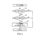
- FIG. 5 is a flowchart showing lock control by the lock mechanism control unit 86.
- the lock mechanism control unit 86 determines whether or not a lock condition is satisfied in step S1. Specifically, the lock condition determination unit 86A determines whether or not all of the above conditions 1 to 3 are satisfied.
- the lock condition determination unit 86A refers to the input position signal D3 and determines whether or not the link mechanism 36 is in the unlocked state. Condition 1 is satisfied when the unlock position signal D3 is input.
- the lock condition determining unit 86A determines whether or not the current throttle opening is zero with reference to the input throttle opening signal D1. Condition 2 is satisfied when the throttle opening is zero, that is, when the throttle valve is closed.
- the lock condition determination unit 86A determines whether or not the current vehicle speed is slower than a predetermined vehicle speed (for example, 10 km / h) with reference to the input vehicle speed signal D2.
- Condition 3 is established when the current vehicle speed is slower than the predetermined vehicle speed.
- the lock mechanism control unit 86 ends the lock control.
- the lock mechanism control unit 86 determines whether or not the occupant has an intention to lock the link mechanism 36 in step S2. Specifically, the signal input determination unit 86B determines whether or not the input condition is satisfied. The input condition is satisfied when the following condition 4 is satisfied. Condition 4: The operation signal D4 is input.
- the signal input determination unit 86B determines whether or not the operation signal D4 is input. Condition 4 is satisfied when the operation signal D4 is input.
- the operation signal D4 may be input before the lock condition is satisfied, or may be input after the lock condition is satisfied.
- the lock mechanism control unit 86 ends the lock control.
- the lock mechanism control unit 86 sets the link mechanism 36 in the locked state in step S3. Specifically, the lock control unit 86C drives the actuator 78 to bring the link mechanism 36 into a locked state. Thereafter, the lock mechanism control unit 86 ends the lock control.
- notification control by the notification control unit 86D will be described.
- the notification control unit 86D controls the lock notification unit 112 to notify the lock state of the link mechanism 36.
- the notification condition is satisfied when the vehicle travels for a predetermined time (for example, 3 seconds) at a vehicle speed lower than the vehicle speed when the link mechanism 36 is locked.
- the vehicle speed may not be constant within the predetermined time.
- FIG. 6 is a flowchart showing notification control by the notification control unit 86D.
- step S11 the notification control unit 86D determines whether or not the link mechanism 36 is in a locked state. Specifically, the notification control unit 86D determines whether or not the link mechanism 36 is in a locked state with reference to the input position signal D3. When the lock position signal D3 is input, the link mechanism 36 is in a locked state.
- step S11: NO When the link mechanism 36 is not in the locked state (step S11: NO), the notification control unit 86D ends the notification control.
- step S11: YES the notification control unit 86D determines whether or not the notification condition is satisfied in step S12. Specifically, the notification condition determination unit 116 determines whether or not the vehicle travels for a predetermined time at a vehicle speed lower than the vehicle speed when the link mechanism 36 is locked.
- step S12 If the notification condition is not satisfied (step S12: NO), the notification control unit 86D ends the notification control. On the other hand, when the notification condition is satisfied (step S12: YES), the notification control unit 86D performs notification by the lock notification unit 112 in step S13. Specifically, the operation of the lock notification unit 112 is controlled to notify the occupant that the link mechanism 36 is in a locked state. Thereafter, the notification control unit 86D ends the notification control.
- the notification condition may be satisfied when the vehicle speed when the link mechanism 36 is locked is equal to or higher than the first vehicle speed.
- the first vehicle speed is lower than the vehicle speed when the link mechanism 36 is locked, and is not zero.
- the first vehicle speed is, for example, 6 km / h.
- the lock state of the link mechanism 36 can be notified immediately after the link mechanism 36 is locked. It becomes easy for the passenger to recognize the locked state of the link mechanism 36.
- the notification by the lock notification unit 112 may be terminated when the current vehicle speed is lower than the first vehicle speed.
- the notification by the lock notification unit 112 is performed by sound and display, for example, when the current vehicle speed becomes lower than the first vehicle speed, the notification by sound may be terminated.
- the notification condition may be satisfied when the vehicle speed when the link mechanism 36 is locked is higher than the first vehicle speed.
- the notification condition may be satisfied when a predetermined time (for example, 3 seconds) elapses after the link mechanism 36 is locked. If a certain amount of time elapses after the link mechanism 36 is locked, there is a possibility that the occupant does not accurately recognize the state of the link mechanism 36. In such a case, the occupant can recognize the state of the link mechanism 36.
- a predetermined time for example, 3 seconds
- the notification condition may be satisfied when the vehicle speed when the link mechanism 36 is locked is equal to or higher than a predetermined vehicle speed and the vehicle travels at the vehicle speed for a predetermined time.
- the vehicle speed may not be constant within the predetermined time.
- the notification by the lock notification unit 112 may be terminated on the same basis as when the notification conditions according to Application Example 1 are employed.
Landscapes
- Engineering & Computer Science (AREA)
- Mechanical Engineering (AREA)
- Axle Suspensions And Sidecars For Cycles (AREA)
- Vehicle Body Suspensions (AREA)
- Automatic Cycles, And Cycles In General (AREA)
Abstract
Description
鞍乗型車両10は、図1に示すように、車体フレーム12、一対の前輪14L、14R及び後輪16を備える。
図2を参照しながら、前輪支持機構30について説明する。前輪支持機構30は、リンク機構36、サスペンション38及びダンパ40を備える。
リンク機構36は、一対の前輪14L、14Rを車体フレーム12(例えば、ヘッドパイプ20の前方に配置されるフロントフレーム)に接続する。リンク機構36は、左上アーム42L、右上アーム42R、左下アーム44L、右下アーム44R、左ナックルアーム46L及び右ナックルアーム46Rを備える。
図2に示すように、サスペンション38は、リンク機構36に配置される。サスペンション38は、シリンダ54と、ピストン56とを備える。
図2に示すように、ダンパ40は、リンク機構36に配置される。ダンパ40は、ピストン62と、シリンダ64とを備える。ピストン62は、左下アーム44Lに対して、揺動可能に取り付けられる。シリンダ64は、右上アーム42Rに対して、揺動可能に取り付けられる。
図4を参照しながら、鞍乗型車両10が備える制御装置84について説明する。図4は、制御装置84に入力される信号及び制御装置84から出力される信号を説明するためのブロック図である。
続いて、ロック機構制御部86がリンク機構36をロック状態にするための制御(ロック機構制御部86によるロック制御)について説明する。なお、ロック機構制御部86によるロック制御は、以下のものに限定されない。
条件1:リンク機構36がロック解除状態である。
条件2:現在のスロットル開度がゼロである。
条件3:現在の車速が所定の車速よりも遅い。
条件4:操作信号D4が入力されている。
続いて、報知制御部86Dによる報知制御について説明する。報知制御部86Dは、報知条件を満たす場合に、ロック報知部112を制御し、リンク機構36のロック状態を報知する。
報知条件は、リンク機構36がロックされている状態での車速が第1の車速以上である場合に成立してもよい。ここで、第1の車速は、リンク機構36がロックされたときの車速よりも低速であって、且つ、ゼロではない。第1の車速は、例えば、6km/hである。
報知条件は、リンク機構36がロックされてから所定時間(例えば、3秒)経過した場合に成立してもよい。リンク機構36がロックされてからある程度の時間が経過すると、乗員がリンク機構36の状態を正確に認識していない可能性がある。このような場合に、リンク機構36の状態を乗員に認識させることができる。
報知条件は、リンク機構36がロックされている状態での車速が所定の車速以上であって、且つ、当該車速で所定時間走行している場合に成立してもよい。所定時間内において、車速は一定でなくてもよい。このような報知条件を採用する場合には、応用例1に係る報知条件を採用する場合と同様な基準で、ロック報知部112による報知を終了してもよい。
Claims (6)
- 車体フレームと、
一対の前輪と、
前記一対の前輪を前記車体フレームに接続するリンク機構と、
前記リンク機構の動作を規制することで前記リンク機構をロック状態にし、前記リンク機構の動作を許容することで前記リンク機構をロック解除状態にするロック機構と、
前記ロック機構による前記リンク機構のロック及びロック解除を制御する制御部と、
前記ロック機構が前記リンク機構をロックしている状態で車両が走行していることを報知する報知部とを備える、鞍乗型車両。 - 請求項1に記載の鞍乗型車両であって、
前記報知部は、前記ロック機構が前記リンク機構をロックしている状態で車両が所定の車速以上で走行していることを報知する、鞍乗型車両。 - 請求項1又は2に記載の鞍乗型車両であって、
前記報知部は、前記ロック機構が前記リンク機構をロックしている状態で車両が所定時間走行していることを報知する、鞍乗型車両。 - 請求項1に記載の鞍乗型車両であって、
前記報知部は、前記ロック機構が前記リンク機構をロックした後、前記リンク機構がロックされたときの車速よりも遅い車速で所定時間走行している場合に、前記ロック機構により前記リンク機構がロックされていることを報知する、鞍乗型車両。 - 請求項1に記載の鞍乗型車両であって、
前記ロック機構が前記リンク機構をロックしている状態での車速及び走行時間の少なくとも一方に基づいて、前記リンク機構のロック状態を報知するための報知条件を満たすか判断する報知条件判断部と、
前記報知条件を満たす場合に、前記報知部を制御し、前記リンク機構のロック状態を報知する報知制御部とをさらに備える、鞍乗型車両。 - 請求項1~5の何れか1項に記載の鞍乗型車両であって、
前記一対の前輪に生じる逆位相の振動を減衰するダンパをさらに備え、
前記ロック機構は、前記ダンパの動作を規制することで前記リンク機構をロック状態にし、前記ダンパの動作を許容することで前記リンク機構をロック解除状態にする、鞍乗型車両。
Priority Applications (5)
| Application Number | Priority Date | Filing Date | Title |
|---|---|---|---|
| JP2016510246A JPWO2015146660A1 (ja) | 2014-03-24 | 2015-03-16 | 鞍乗型車両 |
| CA2943760A CA2943760C (en) | 2014-03-24 | 2015-03-16 | Saddle riding type vehicle with two front wheels and lockable linkage |
| ES15769978T ES2791196T3 (es) | 2014-03-24 | 2015-03-16 | Vehículo de montar a horcajadas |
| US15/128,454 US20170101150A1 (en) | 2014-03-24 | 2015-03-16 | Saddle riding type vehicle |
| EP15769978.6A EP3124367B1 (en) | 2014-03-24 | 2015-03-16 | Saddled vehicle |
Applications Claiming Priority (2)
| Application Number | Priority Date | Filing Date | Title |
|---|---|---|---|
| JP2014-060804 | 2014-03-24 | ||
| JP2014060804 | 2014-03-24 |
Publications (1)
| Publication Number | Publication Date |
|---|---|
| WO2015146660A1 true WO2015146660A1 (ja) | 2015-10-01 |
Family
ID=54195183
Family Applications (1)
| Application Number | Title | Priority Date | Filing Date |
|---|---|---|---|
| PCT/JP2015/057635 Ceased WO2015146660A1 (ja) | 2014-03-24 | 2015-03-16 | 鞍乗型車両 |
Country Status (6)
| Country | Link |
|---|---|
| US (1) | US20170101150A1 (ja) |
| EP (1) | EP3124367B1 (ja) |
| JP (1) | JPWO2015146660A1 (ja) |
| CA (1) | CA2943760C (ja) |
| ES (1) | ES2791196T3 (ja) |
| WO (1) | WO2015146660A1 (ja) |
Cited By (7)
| Publication number | Priority date | Publication date | Assignee | Title |
|---|---|---|---|---|
| IT201600129489A1 (it) * | 2016-12-21 | 2018-06-21 | Piaggio & C Spa | Avantreno di motoveicolo rollante con blocco di rollio |
| CN110949592A (zh) * | 2018-09-26 | 2020-04-03 | 上海飞田通信股份有限公司 | 电动自行车智能速控安全系统 |
| US10953946B2 (en) | 2016-12-21 | 2021-03-23 | Piaggio & C. S.P.A. | Forecarriage of a rolling motor vehicle with rolling block |
| US11230339B2 (en) | 2016-12-21 | 2022-01-25 | Piaggio & C. S.P.A | Forecarriage of a rolling motor vehicle with rolling block |
| US11254181B2 (en) | 2016-12-21 | 2022-02-22 | Piaggio & C. S.P.A | Forecarriage of a rolling motor vehicle with roll control |
| JP2022528168A (ja) * | 2019-04-10 | 2022-06-08 | ピアッジオ エ チ.ソシエタ ペル アチオニ | 傾きロック装置を備えた傾斜式車両 |
| US11420702B2 (en) | 2016-12-21 | 2022-08-23 | Piaggio & C. S.P.A. | Forecarriage of a rolling motor vehicle with roll block |
Families Citing this family (7)
| Publication number | Priority date | Publication date | Assignee | Title |
|---|---|---|---|---|
| ES2727622T3 (es) * | 2014-03-24 | 2019-10-17 | Yamaha Motor Co Ltd | Vehículo de montar a horcajadas |
| JPWO2015146679A1 (ja) * | 2014-03-24 | 2017-04-13 | ヤマハ発動機株式会社 | 鞍乗型車両 |
| JP2017065531A (ja) * | 2015-09-30 | 2017-04-06 | ヤマハ発動機株式会社 | 車両 |
| JP2017065530A (ja) * | 2015-09-30 | 2017-04-06 | ヤマハ発動機株式会社 | 車両 |
| JP2018144698A (ja) * | 2017-03-07 | 2018-09-20 | ヤマハ発動機株式会社 | 車両 |
| JP2018144697A (ja) * | 2017-03-07 | 2018-09-20 | ヤマハ発動機株式会社 | 車両 |
| IT202200012251A1 (it) * | 2022-06-09 | 2023-12-09 | Piaggio & C Spa | Motoveicolo rollante a tre o quattro ruote comprendente una unità di controllo elettronico di un sistema di bloccaggio del rollio |
Citations (4)
| Publication number | Priority date | Publication date | Assignee | Title |
|---|---|---|---|---|
| JP2005313876A (ja) * | 2004-02-04 | 2005-11-10 | Piaggio & C Spa | 車両用アンチロール装置 |
| JP2009286266A (ja) * | 2008-05-29 | 2009-12-10 | Yamaha Motor Co Ltd | 鞍乗型車両 |
| JP2011195100A (ja) * | 2010-03-23 | 2011-10-06 | Honda Motor Co Ltd | 鞍乗型揺動四輪車両 |
| JP2012025370A (ja) * | 2010-06-25 | 2012-02-09 | Equos Research Co Ltd | 車両 |
Family Cites Families (2)
| Publication number | Priority date | Publication date | Assignee | Title |
|---|---|---|---|---|
| PT1363794E (pt) * | 2001-02-27 | 2006-10-31 | Aprilia Spa | Veiculo de tres rodas com sistema de suspensao basculante |
| JP5237783B2 (ja) * | 2008-12-19 | 2013-07-17 | ヤマハ発動機株式会社 | 鞍乗型車両 |
-
2015
- 2015-03-16 ES ES15769978T patent/ES2791196T3/es active Active
- 2015-03-16 JP JP2016510246A patent/JPWO2015146660A1/ja active Pending
- 2015-03-16 CA CA2943760A patent/CA2943760C/en active Active
- 2015-03-16 WO PCT/JP2015/057635 patent/WO2015146660A1/ja not_active Ceased
- 2015-03-16 US US15/128,454 patent/US20170101150A1/en not_active Abandoned
- 2015-03-16 EP EP15769978.6A patent/EP3124367B1/en active Active
Patent Citations (4)
| Publication number | Priority date | Publication date | Assignee | Title |
|---|---|---|---|---|
| JP2005313876A (ja) * | 2004-02-04 | 2005-11-10 | Piaggio & C Spa | 車両用アンチロール装置 |
| JP2009286266A (ja) * | 2008-05-29 | 2009-12-10 | Yamaha Motor Co Ltd | 鞍乗型車両 |
| JP2011195100A (ja) * | 2010-03-23 | 2011-10-06 | Honda Motor Co Ltd | 鞍乗型揺動四輪車両 |
| JP2012025370A (ja) * | 2010-06-25 | 2012-02-09 | Equos Research Co Ltd | 車両 |
Non-Patent Citations (1)
| Title |
|---|
| See also references of EP3124367A4 * |
Cited By (10)
| Publication number | Priority date | Publication date | Assignee | Title |
|---|---|---|---|---|
| IT201600129489A1 (it) * | 2016-12-21 | 2018-06-21 | Piaggio & C Spa | Avantreno di motoveicolo rollante con blocco di rollio |
| WO2018116211A1 (en) * | 2016-12-21 | 2018-06-28 | Piaggio & C. S.P.A. | Forecarriage of a rolling motor vehicle with rolling rock |
| US10953946B2 (en) | 2016-12-21 | 2021-03-23 | Piaggio & C. S.P.A. | Forecarriage of a rolling motor vehicle with rolling block |
| US11046136B2 (en) | 2016-12-21 | 2021-06-29 | Piaggio & C. S.P.A. | Forecarriage of a rolling motor vehicle with rolling block |
| US11230339B2 (en) | 2016-12-21 | 2022-01-25 | Piaggio & C. S.P.A | Forecarriage of a rolling motor vehicle with rolling block |
| US11254181B2 (en) | 2016-12-21 | 2022-02-22 | Piaggio & C. S.P.A | Forecarriage of a rolling motor vehicle with roll control |
| US11420702B2 (en) | 2016-12-21 | 2022-08-23 | Piaggio & C. S.P.A. | Forecarriage of a rolling motor vehicle with roll block |
| CN110949592A (zh) * | 2018-09-26 | 2020-04-03 | 上海飞田通信股份有限公司 | 电动自行车智能速控安全系统 |
| JP2022528168A (ja) * | 2019-04-10 | 2022-06-08 | ピアッジオ エ チ.ソシエタ ペル アチオニ | 傾きロック装置を備えた傾斜式車両 |
| JP7498193B2 (ja) | 2019-04-10 | 2024-06-11 | ピアッジオ エ チ.ソシエタ ペル アチオニ | 傾きロック装置を備えた傾斜式車両 |
Also Published As
| Publication number | Publication date |
|---|---|
| CA2943760A1 (en) | 2015-10-01 |
| EP3124367B1 (en) | 2020-05-06 |
| JPWO2015146660A1 (ja) | 2017-04-13 |
| EP3124367A1 (en) | 2017-02-01 |
| ES2791196T3 (es) | 2020-11-03 |
| EP3124367A4 (en) | 2017-07-26 |
| US20170101150A1 (en) | 2017-04-13 |
| CA2943760C (en) | 2019-02-12 |
Similar Documents
| Publication | Publication Date | Title |
|---|---|---|
| WO2015146660A1 (ja) | 鞍乗型車両 | |
| JPWO2015146679A1 (ja) | 鞍乗型車両 | |
| JP6074543B2 (ja) | 鞍乗型車両 | |
| US10668972B2 (en) | Saddle riding type vehicle | |
| EP3157805B1 (en) | Improved control system of the trim of vehicles with more than two wheels | |
| WO2012063610A1 (ja) | 車両のサスペンション制御装置 | |
| US10005438B2 (en) | Brake system and vehicle | |
| JP5798682B2 (ja) | ステアリングダンパおよびそれを備えた鞍乗型車両 | |
| JP2021146943A (ja) | サスペンション制御装置 | |
| JP6640590B2 (ja) | 車両制振装置 | |
| CN215763021U (zh) | 减振器及车辆 | |
| JP2008008384A (ja) | 油圧装置、及びこれを備えた産業車両の車輪懸架装置 | |
| WO2024203025A1 (ja) | 制御システム、鞍乗型車両、制御方法、およびプログラム | |
| JP2005343313A (ja) | 産業車両の制御装置 | |
| JP2018043721A (ja) | 車両用サスペンション装置 |
Legal Events
| Date | Code | Title | Description |
|---|---|---|---|
| 121 | Ep: the epo has been informed by wipo that ep was designated in this application |
Ref document number: 15769978 Country of ref document: EP Kind code of ref document: A1 |
|
| ENP | Entry into the national phase |
Ref document number: 2016510246 Country of ref document: JP Kind code of ref document: A |
|
| ENP | Entry into the national phase |
Ref document number: 2943760 Country of ref document: CA |
|
| REEP | Request for entry into the european phase |
Ref document number: 2015769978 Country of ref document: EP |
|
| WWE | Wipo information: entry into national phase |
Ref document number: IDP00201606360 Country of ref document: ID Ref document number: 15128454 Country of ref document: US Ref document number: 2015769978 Country of ref document: EP |
|
| NENP | Non-entry into the national phase |
Ref country code: DE |