WO2015146868A1 - ワイパシステム制御方法及びワイパシステム制御装置 - Google Patents
ワイパシステム制御方法及びワイパシステム制御装置 Download PDFInfo
- Publication number
- WO2015146868A1 WO2015146868A1 PCT/JP2015/058635 JP2015058635W WO2015146868A1 WO 2015146868 A1 WO2015146868 A1 WO 2015146868A1 JP 2015058635 W JP2015058635 W JP 2015058635W WO 2015146868 A1 WO2015146868 A1 WO 2015146868A1
- Authority
- WO
- WIPO (PCT)
- Prior art keywords
- wiper
- wiping
- wiper system
- heavy rain
- blade
- Prior art date
- Legal status (The legal status is an assumption and is not a legal conclusion. Google has not performed a legal analysis and makes no representation as to the accuracy of the status listed.)
- Ceased
Links
Images




Classifications
-
- B—PERFORMING OPERATIONS; TRANSPORTING
- B60—VEHICLES IN GENERAL
- B60S—SERVICING, CLEANING, REPAIRING, SUPPORTING, LIFTING, OR MANOEUVRING OF VEHICLES, NOT OTHERWISE PROVIDED FOR
- B60S1/00—Cleaning of vehicles
- B60S1/02—Cleaning windscreens, windows or optical devices
- B60S1/04—Wipers or the like, e.g. scrapers
- B60S1/06—Wipers or the like, e.g. scrapers characterised by the drive
- B60S1/08—Wipers or the like, e.g. scrapers characterised by the drive electrically driven
- B60S1/0818—Wipers or the like, e.g. scrapers characterised by the drive electrically driven including control systems responsive to external conditions, e.g. by detection of moisture, dirt or the like
-
- B—PERFORMING OPERATIONS; TRANSPORTING
- B60—VEHICLES IN GENERAL
- B60S—SERVICING, CLEANING, REPAIRING, SUPPORTING, LIFTING, OR MANOEUVRING OF VEHICLES, NOT OTHERWISE PROVIDED FOR
- B60S1/00—Cleaning of vehicles
- B60S1/02—Cleaning windscreens, windows or optical devices
- B60S1/04—Wipers or the like, e.g. scrapers
- B60S1/06—Wipers or the like, e.g. scrapers characterised by the drive
- B60S1/08—Wipers or the like, e.g. scrapers characterised by the drive electrically driven
- B60S1/0818—Wipers or the like, e.g. scrapers characterised by the drive electrically driven including control systems responsive to external conditions, e.g. by detection of moisture, dirt or the like
- B60S1/0822—Wipers or the like, e.g. scrapers characterised by the drive electrically driven including control systems responsive to external conditions, e.g. by detection of moisture, dirt or the like characterized by the arrangement or type of detection means
- B60S1/0833—Optical rain sensor
Definitions
- the present invention relates to a control method and a control device for a wiper system mounted on a vehicle such as an automobile, and more particularly to a technique effective when applied to a wiper system provided with a raindrop sensor (rain sensor) for detecting rainfall.
- a raindrop sensor rain sensor
- an increasing number of vehicles are equipped with an auto wiper system that detects rainfall and automatically controls the operation of the wiper device.
- the wiper operation is controlled in accordance with the rainfall, and from INT (intermittent operation state) to Lo (low speed operation state: normal operation state) and Hi (high speed operation state) as the rainfall increases.
- the wiper speed is switched appropriately (infinitely depending on the vehicle model).
- Patent Document 1 Conventionally, a configuration as disclosed in Patent Document 1 has been proposed as a means for dealing with a large amount of rainfall such as local heavy rain.
- a wiper device two types of wipers are used as a wiper device: a reciprocating swing type wiper and a rotary wiper.
- the reciprocating rocking wiper is stopped and the rotary wiper is operated. In this way, even during heavy rain, the rain is removed from the windshield to increase the degree of transparency and ensure the driver's visibility.
- a wiper system control method includes a wiper blade that performs a reciprocating wiping operation on a wiping surface, and a raindrop sensor that detects a current rainfall amount based on water droplets adhering to the wiping surface.
- the system control method is characterized in that when a rain of a predetermined amount or more is detected by the raindrop sensor, the wiping range of the wiper blade is narrower than a normal wiping operation.
- the wiper blade when the rain of a predetermined amount or more is detected, the wiper blade performs the wiping operation in a narrower range than usual. Therefore, the time required for one wiping operation is shortened, and the range is limited even during heavy rain. Frequently wiped out. Therefore, even in heavy rain in which a large amount of rain adheres to the windshield immediately after the wiping operation, the raindrops are quickly wiped off, and the field of view necessary for the driving operation is ensured.
- the wiper system has a low speed operation state (Lo) in which the wiper blade is operated at a low speed and a high speed operation state (Hi) in which the wiper blade is operated at a higher speed than in the low speed operation state. If the raindrop sensor detects a predetermined amount or more of rain, the wiper blade disposed on the driver side is set in the vicinity of the driver's front field of view and is in a heavy rain wiping area narrower than the normal wiping operation range. Then, it may be operated in the high-speed operation state (Hi).
- the wiper system control device of the present invention includes a wiper blade that performs a reciprocating wiping operation on a wiping surface, and a raindrop sensor that detects a current rainfall amount based on water droplets adhering to the wiping surface.
- a control device for controlling the operation of the wiper system wherein a rainfall amount determination unit that determines a current rainfall state based on an output signal of the raindrop sensor, and a rainfall amount that is greater than or equal to a predetermined value in the rainfall state determination unit And an operation mode change unit that changes the operation mode of the wiper blade to a heavy rain mode that narrows the wiping range of the wiper blade when compared with a normal wiping operation.
- the operation mode changing unit changes the operation mode of the wiper blade to the heavy rain mode, and the wiping range is set. Narrower than normal wiping operation. As a result, the time required for one wipe operation of the wiper blade is shortened, and the range is frequently wiped even during heavy rain. Therefore, even in heavy rain in which a large amount of rain adheres to the windshield immediately after the wiping operation, the raindrops are quickly wiped off, and the field of view necessary for the driving operation is ensured.
- the wiper system has a low speed operation state (Lo) in which the wiper blade is operated at a low speed and a high speed operation state (Hi) in which the wiper blade is operated at a higher speed than in the low speed operation state.
- the operation mode change unit in the heavy rain mode, is configured to remove the wiper blade disposed on the driver side in a heavy rain wiping region narrower than a normal wiping operation range set near the driver's front view. Then, it may be operated in the high-speed operation state (Hi).
- the wiper system control method of the present invention in a wiper system having a raindrop sensor, when the raindrop sensor detects a predetermined amount or more of rain, the wiper blade wiping range is narrower than the normal wiping operation. Even at times, the predetermined wiping range is frequently wiped, and the field of view necessary for the driving operation can be secured. Therefore, even in the case of local heavy rain, it is possible to secure a field of view until the vehicle is evacuated to a safe place.
- the present invention can be applied to a conventional wiper system by improving the control software without changing the device configuration. Therefore, the visibility during heavy rain can be ensured without complicating the system structure and increasing the cost. Is possible.
- the operation mode changing unit changes the operation mode of the wiper blade to heavy rain. Since the mode is changed to the mode and the wiping range is narrower than the normal wiping operation, the predetermined wiping range is frequently wiped even during heavy rain, and the field of view necessary for the driving operation can be secured. Therefore, even in the case of local heavy rain, it is possible to secure a field of view until the vehicle is evacuated to a safe place.
- the present invention can be applied to a conventional wiper system by improving the control software without changing the device configuration. Therefore, the visibility during heavy rain can be ensured without complicating the system structure and increasing the cost. Is possible.
- FIG. 1 is an explanatory diagram showing an overall configuration of a wiper system driven by a wiper control method / control apparatus according to an embodiment of the present invention.
- the wiper system of FIG. 1 includes a wiper arm 1a on the driver's seat side and a wiper arm 1b on the passenger seat side.
- the wiper arms 1a and 1b are swingably provided on the vehicle body.
- the wiper system of FIG. 1 includes a so-called auto wiper system, and when the wiper switch is set to Auto (auto wiper mode), the operation is automatically controlled according to the rainfall.
- a wiper blade 2a on the driver's seat side and a wiper blade 2b on the passenger seat side are attached to each wiper arm 1a, 1b.
- the wiper blades 2a and 2b (hereinafter abbreviated as blades 2a and 2b) are in elastic contact with the windshield (wiping surface) 3 by a spring member (not shown) incorporated in the wiper arms 1a and 1b.
- the vehicle body is provided with two wiper shafts (pivot shafts) 4a and 4b.
- the wiper arms 1a and 1b are respectively attached to the wiper shafts 4a and 4b at the base ends.
- “a, b” in the reference numerals indicates members and portions related to the driver's seat side and the passenger seat side, respectively.
- this system is provided with two electric motors 6a and 6b (hereinafter abbreviated as motors 6a and 6b) that are PWM-duty controlled.
- the motors 6 a and 6 b are constituted by a motor body 7 and a speed reduction mechanism 8.
- the motors 6a and 6b are driven and controlled by the wiper control device 10 and rotate forward and backward.
- a wiper control device 10a that drives and controls the motor 6a is connected to an ECU 11 that is a vehicle-side controller via an in-vehicle LAN 12.
- the rainfall amount information from the raindrop sensor 9 From the ECU 11 to the wiper control device 10a, the rainfall amount information from the raindrop sensor 9, switch information indicating the state of the wiper switch (Auto, ON / OFF, Lo, Hi, INT), engine activation information, etc. Is input via.
- the wiper control devices 10a and 10b are connected by a communication line 13.
- a raindrop sensor 9 for detecting the rainfall is attached to the center of the windshield 3.
- the raindrop sensor 9 includes a light emitting element such as an LED and a light receiving element such as a photodiode. Infrared light emitted from the light emitting element is reflected by the windshield surface and enters the light receiving element. If raindrops are present on the windshield 3, light rays from the light emitting elements are not reflected by the windshield, but pass through the raindrops or are scattered by the raindrops. As a result, when there are raindrops, the amount of light received by the light receiving element is reduced compared to when there are no raindrops.
- the wiper control device 10 determines the current rainfall state from the output change of the raindrop sensor 9, and automatically controls the operation / stop of the wiper and its operation (Lo, Hi, INT).
- the motors 6a and 6b are feedback controlled (PI control) based on the positional information of the blades 2a and 2b.
- target speeds of both blades are set corresponding to the positions of the blades 2a and 2b.
- the target speed is stored in advance in the wiper control devices 10a and 10b in the form of a map or the like.
- the relationship between the rainfall and the blade target speed is also stored in the form of a map or the like in advance.
- the wiper control devices 10a and 10b detect the current positions of the blades 2a and 2b, and also detect the moving speeds of the blades 2a and 2b from the rotational speeds of the wiper shafts 4a and 4b.
- the wiper control devices 10a and 10b compare the current speed of the blades 2a and 2b with the target speed of the blades 2a and 2b at the current position.
- the wiper control devices 10a and 10b appropriately control the motors 6a and 6b according to the difference between the target speed and the current speed (in the case of the auto wiper mode, taking into account the rainfall).
- FIG. 2 is an explanatory diagram showing the configuration of the motor 6a.
- the motor 6b has the same configuration.
- the motor 6 a is configured by the motor body 7 and the speed reduction mechanism 8.
- a rotor 33 is rotatably disposed in the motor body 7.
- a worm 35 is formed on the rotating shaft 34 of the rotor 33.
- the worm 35 meshes with a worm wheel 36 disposed in the speed reduction mechanism 8.
- the worm wheel 36 is attached to the wiper shaft 4a.
- a sensor magnet 31 is further attached to the wiper shaft 4 a or the worm wheel 36.
- a control board (not shown) is provided on the speed reduction mechanism 8 side of the motor 6a.
- the sensor magnet 31 is disposed to face the rotary encoder IC 32 attached to the control board.
- the rotary encoder IC 32 is an IC having the functions of both an MR sensor and a Hall IC sensor.
- the wiper control device 10a detects both the pulse and the angle by the sensor magnet 31 and the rotary encoder IC 32, and controls the motor 6a. That is, the number of rotations of the wiper shaft 4a is detected by a pulse generated as the sensor magnet 31 rotates. Further, the rotation angle of the wiper shaft 4a is detected by the change of the output voltage accompanying the magnetic change of the sensor magnet 31. By detecting the rotational speed of the wiper shaft 4a, the rotational speed of the wiper shaft 4a is calculated, and the speed of the blade 2a is detected. There is a predetermined relationship between the output voltage value of the rotary encoder IC32 and the rotation angle of the wiper shaft 4a, and the current position of the blade 2a is detected based on this voltage value.
- Control information such as the speed and current position of the blades 2 a and 2 b is exchanged between the wiper control devices 10 a and 10 b via the communication line 13.
- the wiper control devices 10a and 10b synchronously control the motors 6a and 6b based on the positional relationship between both blades. That is, the wiper control devices 10a and 10b first perform forward / reverse control of the motors 6a and 6b based on the blade position on its own side. At the same time, the wiper control devices 10a and 10b control the motors 6a and 6b based on the blade position information of both blades 2a and 2b, and control the wiper system so that the blades do not interfere with each other and the angle difference does not increase. . As a result, the blades 2a and 2b swing between the lower inversion position A and the upper inversion position B in the wiping area 5, and rain or snow attached to the windshield 3 is wiped off.
- a storage position C is provided below the lower inversion position A.
- the blades 2a and 2b are kept at the storage position C when the system is in the off state (when the wiper switch is OFF or when the wiper is stopped in the auto wiper mode).
- the blades 2a and 2b start operating from the storage position C, and the lower inversion position A and upper A reciprocating wiping operation is performed with the reverse position B.
- the blades 2a and 2b pass through the lower inversion position A and are moved to the storage position C and stopped after the return wiping operation.
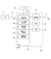
- FIG. 3 is a block diagram showing the configuration of the control system of the wiper control device 10 according to the present invention. Since the wiper control devices 10a and 10b have the same configuration, only the wiper control device 10a will be described in FIG. 3 and the following description.
- the wiper control device 10 a is provided with a CPU 21 and a data transmission / reception unit 22.
- the wiper control device 10a is connected to the ECU 11 via the LAN 12.
- Various types of vehicle information such as a wiper switch setting state (operation mode setting such as Auto, ON / OFF, Lo, Hi, and INT) and an engine start signal are input from the ECU 11 to the wiper control device 10a.
- a ROM 23 and a RAM 24 are further provided in the wiper control device 10a.
- the ROM 23 stores a control program and various control information.
- the RAM 24 stores control data such as the motor speed and the blade current position.
- CPU 21 is a central processing unit.
- the CPU 21 connected to the ECU 11 is the master side
- the CPU of the wiper control device 10b (not shown) is the slave side.
- the CPU 21 of the wiper control device 10 a is connected to the CPU of the wiper control device 10 b via the data transmission / reception unit 22 and the communication line 13. Both CPUs exchange blade position information and motor operation instructions with each other through the communication line 13.
- the CPU 21 on the master side controls the operation of the motor 6a based on the position information of the blade 2b sent from the wiper control device 10b and the position information of itself (blade 2a) according to the state of the wiper switch.
- the CPU on the slave side controls the operation of the motor 6b based on the position information of the blade 2a and the position information of itself (blade 2b) sent from the wiper control device 10a according to the instruction from the wiper control device 10a.
- the CPU 21 is provided with a blade position detector 25 and a blade speed detector 26.
- the blade position detection unit 25 detects the current position of the blade 2a based on the sensor signal from the rotary encoder IC32.
- the blade speed detector 26 detects the current moving speed of the blade 2a.
- the CPU 21 is provided with a rain condition determination unit 27 and an operation mode change unit 28.
- the rain state determination unit 27 determines the current rain state from the output signal of the raindrop sensor 9.
- the operation mode change unit 28 changes the subsequent operation mode of the blade 2a when the rainfall state determination unit 27 determines that the amount of rainfall is large and is currently “heavy rain state”.
- the CPU 21 is provided with a drive control instruction unit 29.
- the drive control instruction unit 29 instructs the motor 6 a on the rotation direction, duty, etc., and operates the blade 2 a appropriately in the wiping area 5.
- the drive control instruction unit 29 switches the wiper operation to the “heavy rain mode”, operates the blade 2a in a limited narrow wiping range, and secures the driver's front view.
- FIG. 4 is a flowchart showing the procedure of the control process according to the present invention.
- the process of FIG. 4 is executed by the wiper control devices 10a and 10b.
- the current rainfall state is determined (step S1). That is, the rain state determination unit 27 determines whether or not the current rain state is the “heavy rain state” from the output signal of the raindrop sensor 9. For example, if the rainfall state determination unit 27 can determine that the amount of rainfall per hour exceeds 50 mm, the rain state determination unit 27 determines the “heavy rain state”. If the result of this determination is that the rainfall condition is not heavy rain, the process proceeds to step S2.
- a normal wiping operation according to the switch state Auto, Lo, Hi, INT
- the routine is exited.
- FIG. 5 is an explanatory diagram showing the blade operation in the “heavy rain mode”.
- the blade 2a is only in the wiping region X having a limited narrow wiping angle ⁇ (for example, 30 ° ⁇ ⁇ ⁇ 45 °).
- the heavy rain wiping area X is set in the vicinity of the driver's front view.
- the blade 2a wipes the range of the region X by Hi operation (high speed operation state).
- the operating range of the blade 2a is narrowed, and the blade 2a is operated by the Hi operation even when the current operation is the Lo operation (low speed operation state) or INT (intermittent operation state).
- the blade 2b operates in the same wiping range as usual, but is synchronized so as not to interfere with the blade 2a.
- the wiper system according to the present invention can ensure visibility during heavy rain by using only a reciprocating swing type wiper device without arranging two types of wiper devices having different structures. Further, the present invention can be applied to a conventional wiper system only by improving the control software without changing the apparatus (hardware) configuration. Therefore, the visibility during heavy rain can be ensured without complicating the system structure, and the safety of the vehicle can be improved while suppressing an increase in cost.
- the control mode is shown in which the system operates in the “heavy rain mode” when the heavy rain state is detected in the auto wiper mode.
- the operating state of the heavy rain mode can be selected by the user's intention. That is, for example, if “Heavy rain” (heavy rain mode) is added to the wiper switch and the driver sets the wiper switch to “Heavy rain”, heavy rain mode (Hi operation in a narrow range with the wiper blade on the driver's side limited) May be executed.
- the blade 2b on the passenger seat side is operated in a normal Hi operation in the “heavy rain mode”, but the blade 2b on the passenger seat side may be stopped in the heavy rain mode.
- the wiper system of FIG. 1 an example in which the present invention is applied to a parallel wiping type wiper device that operates the wiper blade in the same direction has been shown.
- the present invention is an opposed wiping type in which the wiper blade operates in opposite directions. It can also be applied to a wiper device.
- the electric motor used in the wiper system according to the present invention is not limited to the motor shown in FIG. 2, and for example, a pulse type motor as shown in FIG. 6 can also be used.
- the electric motor unit 41 in FIG. 6 includes a motor 42 and a gear box 43.
- the rotation of the rotating shaft 44 of the motor 42 is decelerated in the gear box 43 and output to the output shaft 45.
- the rotating shaft 44 is rotatably supported by a bottomed cylindrical yoke 46.
- An armature core 47 around which a coil is wound and a commutator 48 are attached to the rotating shaft 44.
- a plurality of permanent magnets 49 are fixed to the inner surface of the yoke 46.
- the power supply brush 50 is in sliding contact with the commutator 48.
- the speed (number of rotations) of the motor 42 is controlled by the amount of current supplied to the brush 50.
- the case frame 51 of the gear box 43 is attached to the opening side edge of the yoke 46.
- the tip of the rotating shaft 44 protrudes from the yoke 46 and is stored in the case frame 51.
- a worm 52 is formed at the tip of the rotating shaft 44.
- a worm gear 53 is engaged with the worm 52.
- the worm gear 53 is rotatably supported by the case frame 51.
- the worm gear 53 is integrally provided with a first gear 54 having a small diameter on the same axis.
- a large-diameter second gear 55 is engaged with the first gear 54.
- An output shaft 45 that is rotatably supported by the case frame 51 is integrally attached to the second gear 55.
- another worm having a reverse twist direction is formed on the rotary shaft 4 adjacent to the worm 52.
- the rotation of the worm is transmitted to the second gear 55 by a reduction member (not shown) similar to the worm gear 53 and the first gear 54.
- the driving force of the motor 42 is output to the output shaft 45 while being decelerated through the worm 52, the worm gear 53, the first gear 54, and the second gear 55.
- a link mechanism (not shown) of a wiper device such as a crank arm is connected to the output shaft 45.
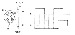
- a multipolar magnetized magnet 56 (hereinafter abbreviated as magnet 56) is attached to the rotating shaft 44.
- a Hall IC 57 (second sensor) is provided in the case frame 51 so as to face the outer peripheral portion of the magnet 56.
- FIG. 7 is an explanatory diagram showing the relationship between the magnet 56 and the Hall IC 57 and the output signal (motor pulse) of the Hall IC 57.
- two Hall ICs 57 are provided at positions having an angle difference of 90 degrees with respect to the center of the rotating shaft 44.
- the magnet 56 is magnetized to 6 poles.
- a pulse output for six cycles is obtained from each Hall IC 57.
- pulse signals whose phases are shifted by 1/4 period are output. Therefore, by detecting the appearance timing of the pulses from the Hall ICs 57A and 57B, the rotation direction of the rotating shaft 44 can be determined, and the forward / return path of the wiper operation can be determined.
- the rotational speed of the rotating shaft 44 can be detected from the period of any one of the pulse outputs. There is a correlation between the rotational speed of the rotating shaft 44 and the blade speed based on the reduction ratio and the link operation ratio. Therefore, the blade speed can also be calculated from the rotational speed of the rotating shaft 44.
- a ring magnet 58 for detecting the absolute position of the blade is attached to the bottom surface of the second gear 55.
- a printed circuit board 59 is attached to the case frame 51.
- a Hall IC 60 (first sensor) is disposed on the printed circuit board 59 so as to face the ring magnet 58.
- the second gear 55 is attached with a crank arm as described above, and rotates about 180 degrees to reciprocate the blade. When the second gear 55 rotates and the blade comes to a preset reference position, the Hall IC 60 and the ring magnet 58 face each other and a reference signal indicating the absolute position is output.
Landscapes
- Engineering & Computer Science (AREA)
- Automation & Control Theory (AREA)
- Mechanical Engineering (AREA)
- Control Of Direct Current Motors (AREA)
- Vehicle Cleaning, Maintenance, Repair, Refitting, And Outriggers (AREA)
- Control Of Electric Motors In General (AREA)
- Investigating Or Analyzing Materials By The Use Of Electric Means (AREA)
Abstract
Description
例えば、前述の実施形態では、オートワイパモードにおいて豪雨状態を検出したとき、システムが「豪雨モード」にて作動する制御形態を示したが、ユーザの意思により、豪雨モードの作動状態を選択できるようにしても良い。すなわち、例えば、ワイパスイッチに「Heavy rain」(豪雨モード)を追加し、ドライバーがワイパスイッチを「Heavy rain」に設定すると、豪雨モード(運転席側のワイパブレードを限定した狭い範囲でHi動作)が実行されるようにしても良い。
3 フロントガラス 4a,4b ワイパ軸
5 払拭範囲 6a,6b 電動モータ
7 モータ本体 8 減速機構
9 雨滴センサ 10 ワイパ制御装置
10a,10b ワイパ制御装置 11 ECU
12 車載LAN 13 通信線
21 CPU 22 データ送受信部
23 ROM 24 RAM
25 ブレード位置検出部 26 ブレード速度検出部
27 降雨状態判定部 28 動作モード変更部
29 駆動制御指示部 31 センサマグネット
32 ロータリーエンコーダIC 33 ロータ
34 回転軸 35 ウォーム
36 ウォームホイール 41 電動モータユニット
42 モータ 43 ギアボックス
44 回転軸 45 出力軸
46 ヨーク 47 アーマチュアコア
48 コンミテータ 49 永久磁石
50 ブラシ 51 ケースフレーム
52 ウォーム 53 ウォーム歯車
54 第1ギア 55 第2ギア
56 多極着磁マグネット 57 ホールIC
57A,57B ホールIC 58 リングマグネット
59 プリント基板 60 ホールIC
A 下反転位置 B 上反転位置
C 格納位置 X 豪雨時払拭領域
θ 豪雨時払拭領域角度
Claims (4)
- 払拭面上にて往復払拭動作を行うワイパブレードと、前記払拭面上に付着した水滴に基づいて現在の降雨量を検知する雨滴センサと、を備えてなるワイパシステムの制御方法であって、
前記雨滴センサにより所定量以上の降雨を検出した場合、前記ワイパブレードの払拭範囲を通常の払拭動作よりも狭めることを特徴とするワイパシステム制御方法。 - 請求項1記載のワイパシステム制御方法において、
前記ワイパシステムは、前記ワイパブレードを低速にて作動させる低速作動状態と、低速作動状態よりも前記ワイパブレードを高速に作動させる高速作動状態を有し、
前記雨滴センサにより所定量以上の降雨を検出した場合、運転者側に配置された前記ワイパブレードを、運転者の前方視界付近に設定され通常の払拭動作範囲よりも狭い豪雨時払拭領域内にて、前記高速作動状態で作動させることを特徴とするワイパシステム制御方法。 - 払拭面上にて往復払拭動作を行うワイパブレードと、前記払拭面上に付着した水滴に基づいて現在の降雨量を検知する雨滴センサと、を備えてなるワイパシステムの動作制御を行う制御装置であって、
前記雨滴センサの出力信号に基づいて現在の降雨状態を判定する降雨状態判定部と、
前記降雨状態判定部にて、降雨量が所定値以上であり豪雨状態と判断された場合、前記ワイパブレードの払拭範囲を通常の払拭動作よりも狭める豪雨モードに前記ワイパブレードの動作形態を変更する動作モード変更部と、を有することを特徴とするワイパシステム制御装置。 - 請求項3記載のワイパシステム制御装置において、
前記ワイパシステムは、前記ワイパブレードを低速にて作動させる低速作動状態と、低速作動状態よりも前記ワイパブレードを高速に作動させる高速作動状態を有し、
前記動作モード変更部は、前記豪雨モードの場合、運転者側に配置された前記ワイパブレードを、運転者の前方視界付近に設定され通常の払拭動作範囲よりも狭い豪雨時払拭領域内にて、前記高速作動状態で作動させることを特徴とするワイパシステム制御装置。
Priority Applications (4)
| Application Number | Priority Date | Filing Date | Title |
|---|---|---|---|
| MX2016012494A MX381771B (es) | 2014-03-27 | 2015-03-21 | Método de control de sistema de limpiaparabrisas y dispositivo de control de sistema de limpiaparabrisas. |
| CN201580016548.8A CN106132787B (zh) | 2014-03-27 | 2015-03-21 | 雨刷器系统控制方法以及雨刷器系统控制装置 |
| EP15769473.8A EP3124335B1 (en) | 2014-03-27 | 2015-03-21 | Wiper system control method and wiper system control device |
| US15/127,047 US10196043B2 (en) | 2014-03-27 | 2015-03-21 | Wiper system control method and wiper system control device |
Applications Claiming Priority (2)
| Application Number | Priority Date | Filing Date | Title |
|---|---|---|---|
| JP2014-066258 | 2014-03-27 | ||
| JP2014066258A JP6349120B2 (ja) | 2014-03-27 | 2014-03-27 | ワイパシステム制御方法及びワイパシステム制御装置 |
Publications (1)
| Publication Number | Publication Date |
|---|---|
| WO2015146868A1 true WO2015146868A1 (ja) | 2015-10-01 |
Family
ID=54195383
Family Applications (1)
| Application Number | Title | Priority Date | Filing Date |
|---|---|---|---|
| PCT/JP2015/058635 Ceased WO2015146868A1 (ja) | 2014-03-27 | 2015-03-21 | ワイパシステム制御方法及びワイパシステム制御装置 |
Country Status (6)
| Country | Link |
|---|---|
| US (1) | US10196043B2 (ja) |
| EP (1) | EP3124335B1 (ja) |
| JP (1) | JP6349120B2 (ja) |
| CN (1) | CN106132787B (ja) |
| MX (1) | MX381771B (ja) |
| WO (1) | WO2015146868A1 (ja) |
Families Citing this family (17)
| Publication number | Priority date | Publication date | Assignee | Title |
|---|---|---|---|---|
| JP6724372B2 (ja) * | 2016-01-14 | 2020-07-15 | 株式会社デンソー | 車両用ワイパ装置及び車両用ワイパ制御プログラム |
| JP6724382B2 (ja) * | 2016-01-21 | 2020-07-15 | 株式会社デンソー | 払拭範囲可変ワイパ装置及び払拭範囲可変ワイパ装置の制御方法 |
| WO2017122826A1 (ja) * | 2016-01-14 | 2017-07-20 | アスモ株式会社 | 車両用ワイパ装置及び車両用ワイパの制御方法 |
| JP6724376B2 (ja) * | 2016-01-19 | 2020-07-15 | 株式会社デンソー | 払拭範囲可変ワイパ装置及び払拭範囲可変ワイパ装置の制御方法 |
| JP6711045B2 (ja) * | 2016-03-16 | 2020-06-17 | 三菱自動車工業株式会社 | 車載撮像装置の水滴除去装置 |
| JP2018127166A (ja) * | 2017-02-10 | 2018-08-16 | 株式会社デンソー | ワイパ装置 |
| CN106627494B (zh) * | 2017-02-28 | 2023-11-14 | 北京汽车集团越野车有限公司 | 一种双电机雨刮系统及其同步控制方法 |
| FR3079189B1 (fr) * | 2018-03-20 | 2021-08-20 | Valeo Systemes Dessuyage | Procede de controle d'un systeme d'essuyage pour vehicule automobile |
| CN111433095A (zh) * | 2018-10-26 | 2020-07-17 | 深圳市大疆创新科技有限公司 | 自动化车辆动作以及相关的系统和方法 |
| US11834147B2 (en) | 2019-12-11 | 2023-12-05 | Rosemount Aerospace Inc. | Programmable pattern-based sweep mechanism for aircraft windscreen wiper system |
| CN112133193B (zh) * | 2020-10-19 | 2021-06-15 | 广州市萌酷信息科技有限责任公司 | 一种用于信息系统集成服务的信息显示屏 |
| KR102842948B1 (ko) * | 2020-12-17 | 2025-08-06 | 현대자동차주식회사 | 차량의 와이퍼 제어 장치 및 그 방법 |
| KR20230081287A (ko) * | 2021-11-30 | 2023-06-07 | 현대자동차주식회사 | 차량 및 그 제어 방법 |
| CN117183989A (zh) * | 2022-05-31 | 2023-12-08 | 北京车和家汽车科技有限公司 | 一种车辆玻璃刮刷方法、装置、车辆及存储介质 |
| CN115416613B (zh) * | 2022-09-08 | 2024-06-21 | 东风汽车集团股份有限公司 | 一种自动雨刮控制系统及控制方法 |
| CN119403707A (zh) * | 2023-03-22 | 2025-02-07 | 株式会社美姿把 | 刮拭装置 |
| JP2025108853A (ja) * | 2024-01-11 | 2025-07-24 | 株式会社ミツバ | 払拭装置 |
Citations (2)
| Publication number | Priority date | Publication date | Assignee | Title |
|---|---|---|---|---|
| JP2005206032A (ja) * | 2004-01-22 | 2005-08-04 | Mitsuba Corp | 車両用ワイパ装置 |
| JP2009023451A (ja) * | 2007-07-18 | 2009-02-05 | Denso Corp | ワイパ制御装置 |
Family Cites Families (14)
| Publication number | Priority date | Publication date | Assignee | Title |
|---|---|---|---|---|
| US4431954A (en) * | 1982-11-26 | 1984-02-14 | General Motors Corporation | Motor vehicle windshield wiper apparatus with storm pattern |
| JPH0815449A (ja) * | 1994-04-26 | 1996-01-19 | Omron Corp | 雨滴検知センサおよびその雨滴検知センサを用いた雨滴計測装置およびその雨滴計測装置を用いたワイパ駆動装置 |
| EP1777130A1 (en) | 1999-05-25 | 2007-04-25 | Toshio Murakami | Method and device for wiping |
| EP1069013A3 (en) * | 1999-07-13 | 2005-01-19 | Jidosha Denki Kogyo Kabushiki Kaisha | Wiper control device |
| US7050949B2 (en) * | 1999-12-28 | 2006-05-23 | Niles Co., Ltd. | Signal processing method and device |
| KR100379959B1 (ko) * | 2000-12-23 | 2003-04-18 | 현대자동차주식회사 | 자동차의 액티브 와이퍼 시스템 |
| EP1623896A4 (en) * | 2003-05-15 | 2006-06-14 | Niles Co Ltd | METHOD AND DEVICE FOR WINDOW WIPER CONTROL |
| DE10360117A1 (de) * | 2003-12-20 | 2005-06-30 | Daimlerchrysler Ag | Scheibenwischeranlage |
| JP4389692B2 (ja) * | 2004-06-24 | 2009-12-24 | 株式会社デンソー | 雨滴検出装置 |
| JP4205032B2 (ja) * | 2004-09-14 | 2009-01-07 | 本田技研工業株式会社 | 車両用オートワイパーシステム |
| JP4779860B2 (ja) * | 2006-08-03 | 2011-09-28 | 株式会社デンソー | 雨滴量検出装置及びワイパー制御装置 |
| JP5074142B2 (ja) * | 2007-10-09 | 2012-11-14 | ナイルス株式会社 | ワイパー制御装置 |
| DE102009029098A1 (de) | 2009-09-02 | 2011-03-03 | Robert Bosch Gmbh | Scheibenwischervorrichtung und Verfahren zum Betreiben einer solchen Scheibenwischervorrichtung |
| JP5525976B2 (ja) * | 2010-09-10 | 2014-06-18 | 株式会社デンソー | ワイパ制御装置 |
-
2014
- 2014-03-27 JP JP2014066258A patent/JP6349120B2/ja active Active
-
2015
- 2015-03-21 MX MX2016012494A patent/MX381771B/es unknown
- 2015-03-21 CN CN201580016548.8A patent/CN106132787B/zh not_active Expired - Fee Related
- 2015-03-21 WO PCT/JP2015/058635 patent/WO2015146868A1/ja not_active Ceased
- 2015-03-21 EP EP15769473.8A patent/EP3124335B1/en active Active
- 2015-03-21 US US15/127,047 patent/US10196043B2/en not_active Expired - Fee Related
Patent Citations (2)
| Publication number | Priority date | Publication date | Assignee | Title |
|---|---|---|---|---|
| JP2005206032A (ja) * | 2004-01-22 | 2005-08-04 | Mitsuba Corp | 車両用ワイパ装置 |
| JP2009023451A (ja) * | 2007-07-18 | 2009-02-05 | Denso Corp | ワイパ制御装置 |
Also Published As
| Publication number | Publication date |
|---|---|
| CN106132787A (zh) | 2016-11-16 |
| EP3124335B1 (en) | 2019-11-27 |
| MX2016012494A (es) | 2017-01-06 |
| CN106132787B (zh) | 2019-05-17 |
| US20170113655A1 (en) | 2017-04-27 |
| JP2015189275A (ja) | 2015-11-02 |
| EP3124335A1 (en) | 2017-02-01 |
| MX381771B (es) | 2025-03-13 |
| US10196043B2 (en) | 2019-02-05 |
| EP3124335A4 (en) | 2017-11-29 |
| JP6349120B2 (ja) | 2018-06-27 |
Similar Documents
| Publication | Publication Date | Title |
|---|---|---|
| JP6349120B2 (ja) | ワイパシステム制御方法及びワイパシステム制御装置 | |
| US20160339872A1 (en) | Wiper control method and wiper control device | |
| JP2005206032A (ja) | 車両用ワイパ装置 | |
| JP6454132B2 (ja) | ワイパシステム | |
| JP6192460B2 (ja) | ワイパ制御方法及びワイパ制御装置 | |
| JP2014083893A (ja) | ワイパ制御装置及びワイパ制御方法 | |
| JP2008174177A (ja) | ワイパ装置 | |
| JP4094723B2 (ja) | ワイパ装置 | |
| JP6802740B2 (ja) | ワイパ制御方法及びワイパ制御装置 | |
| JP6372958B2 (ja) | ワイパシステム | |
| JP6510967B2 (ja) | ワイパ制御装置及びワイパ制御装置の制御方法 | |
| US20080216868A1 (en) | Method for Wiping a Window, and Wiper System, in Particular for a Motor Vehicle | |
| JP2003252179A (ja) | ワイパ装置 | |
| WO2024195813A1 (ja) | 払拭装置 | |
| JP6719927B2 (ja) | ワイパシステム | |
| JP4053775B2 (ja) | モータ制御装置 | |
| JP2022180036A (ja) | ワイパ装置 | |
| JP4476862B2 (ja) | 減速機構付きモータ | |
| JP2015137069A (ja) | ワイパ装置 | |
| JP2010173438A (ja) | ワイパ装置 | |
| JP2003246260A (ja) | ワイパ装置 | |
| JP2005261196A (ja) | 減速機構付きモータ | |
| JP2006089039A (ja) | ワイパ装置 | |
| JP2006069543A (ja) | 減速機構付ワイパモータ | |
| JP2006069544A (ja) | ワイパ制御装置 |
Legal Events
| Date | Code | Title | Description |
|---|---|---|---|
| 121 | Ep: the epo has been informed by wipo that ep was designated in this application |
Ref document number: 15769473 Country of ref document: EP Kind code of ref document: A1 |
|
| WWE | Wipo information: entry into national phase |
Ref document number: 15127047 Country of ref document: US |
|
| WWE | Wipo information: entry into national phase |
Ref document number: MX/A/2016/012494 Country of ref document: MX |
|
| NENP | Non-entry into the national phase |
Ref country code: DE |
|
| REEP | Request for entry into the european phase |
Ref document number: 2015769473 Country of ref document: EP |
|
| WWE | Wipo information: entry into national phase |
Ref document number: 2015769473 Country of ref document: EP |
|
| REG | Reference to national code |
Ref country code: BR Ref legal event code: B01A Ref document number: 112016022216 Country of ref document: BR |
|
| ENP | Entry into the national phase |
Ref document number: 112016022216 Country of ref document: BR Kind code of ref document: A2 Effective date: 20160926 |