WO2015147068A1 - ラジアルギャップ型超電導同期機、着磁装置、及び着磁方法 - Google Patents
ラジアルギャップ型超電導同期機、着磁装置、及び着磁方法 Download PDFInfo
- Publication number
- WO2015147068A1 WO2015147068A1 PCT/JP2015/059155 JP2015059155W WO2015147068A1 WO 2015147068 A1 WO2015147068 A1 WO 2015147068A1 JP 2015059155 W JP2015059155 W JP 2015059155W WO 2015147068 A1 WO2015147068 A1 WO 2015147068A1
- Authority
- WO
- WIPO (PCT)
- Prior art keywords
- wall portion
- superconductor
- rotor
- magnetizing
- synchronous machine
- Prior art date
- Legal status (The legal status is an assumption and is not a legal conclusion. Google has not performed a legal analysis and makes no representation as to the accuracy of the status listed.)
- Ceased
Links
Images






Classifications
-
- H—ELECTRICITY
- H02—GENERATION; CONVERSION OR DISTRIBUTION OF ELECTRIC POWER
- H02K—DYNAMO-ELECTRIC MACHINES
- H02K21/00—Synchronous motors having permanent magnets; Synchronous generators having permanent magnets
- H02K21/12—Synchronous motors having permanent magnets; Synchronous generators having permanent magnets with stationary armatures and rotating magnets
- H02K21/14—Synchronous motors having permanent magnets; Synchronous generators having permanent magnets with stationary armatures and rotating magnets with magnets rotating within the armatures
-
- H—ELECTRICITY
- H01—ELECTRIC ELEMENTS
- H01F—MAGNETS; INDUCTANCES; TRANSFORMERS; SELECTION OF MATERIALS FOR THEIR MAGNETIC PROPERTIES
- H01F13/00—Apparatus or processes for magnetising or demagnetising
- H01F13/003—Methods and devices for magnetising permanent magnets
-
- H—ELECTRICITY
- H01—ELECTRIC ELEMENTS
- H01F—MAGNETS; INDUCTANCES; TRANSFORMERS; SELECTION OF MATERIALS FOR THEIR MAGNETIC PROPERTIES
- H01F6/00—Superconducting magnets; Superconducting coils
-
- H—ELECTRICITY
- H02—GENERATION; CONVERSION OR DISTRIBUTION OF ELECTRIC POWER
- H02K—DYNAMO-ELECTRIC MACHINES
- H02K1/00—Details of the magnetic circuit
- H02K1/02—Details of the magnetic circuit characterised by the magnetic material
-
- H—ELECTRICITY
- H02—GENERATION; CONVERSION OR DISTRIBUTION OF ELECTRIC POWER
- H02K—DYNAMO-ELECTRIC MACHINES
- H02K1/00—Details of the magnetic circuit
- H02K1/06—Details of the magnetic circuit characterised by the shape, form or construction
- H02K1/22—Rotating parts of the magnetic circuit
- H02K1/27—Rotor cores with permanent magnets
- H02K1/2793—Rotors axially facing stators
- H02K1/2795—Rotors axially facing stators the rotor consisting of two or more circumferentially positioned magnets
- H02K1/2796—Rotors axially facing stators the rotor consisting of two or more circumferentially positioned magnets where both axial sides of the rotor face a stator
-
- H—ELECTRICITY
- H02—GENERATION; CONVERSION OR DISTRIBUTION OF ELECTRIC POWER
- H02K—DYNAMO-ELECTRIC MACHINES
- H02K15/00—Processes or apparatus specially adapted for manufacturing, assembling, maintaining or repairing of dynamo-electric machines
- H02K15/02—Processes or apparatus specially adapted for manufacturing, assembling, maintaining or repairing of dynamo-electric machines of stator or rotor bodies
- H02K15/03—Processes or apparatus specially adapted for manufacturing, assembling, maintaining or repairing of dynamo-electric machines of stator or rotor bodies having permanent magnets
-
- H—ELECTRICITY
- H02—GENERATION; CONVERSION OR DISTRIBUTION OF ELECTRIC POWER
- H02K—DYNAMO-ELECTRIC MACHINES
- H02K55/00—Dynamo-electric machines having windings operating at cryogenic temperatures
- H02K55/02—Dynamo-electric machines having windings operating at cryogenic temperatures of the synchronous type
- H02K55/04—Dynamo-electric machines having windings operating at cryogenic temperatures of the synchronous type with rotating field windings
-
- Y—GENERAL TAGGING OF NEW TECHNOLOGICAL DEVELOPMENTS; GENERAL TAGGING OF CROSS-SECTIONAL TECHNOLOGIES SPANNING OVER SEVERAL SECTIONS OF THE IPC; TECHNICAL SUBJECTS COVERED BY FORMER USPC CROSS-REFERENCE ART COLLECTIONS [XRACs] AND DIGESTS
- Y02—TECHNOLOGIES OR APPLICATIONS FOR MITIGATION OR ADAPTATION AGAINST CLIMATE CHANGE
- Y02E—REDUCTION OF GREENHOUSE GAS [GHG] EMISSIONS, RELATED TO ENERGY GENERATION, TRANSMISSION OR DISTRIBUTION
- Y02E40/00—Technologies for an efficient electrical power generation, transmission or distribution
- Y02E40/60—Superconducting electric elements or equipment; Power systems integrating superconducting elements or equipment
Definitions
- the present invention relates to a radial gap type superconducting synchronous machine, a magnetizing device, and a magnetizing method. More specifically, the present invention relates to a technique for effectively increasing the trapped magnetic flux in an adherend while ensuring practicality.
- Patent Document 1 Japanese Patent No. 5162654 discloses a radial gap type superconducting synchronous machine (hereinafter referred to as a radial gap type superconducting synchronous machine).
- -235625 discloses an axial gap type superconducting synchronous machine (hereinafter referred to as an axial gap type superconducting synchronous machine).
- a radial gap type superconducting synchronous machine is a rotating field type synchronous machine, in which a field portion of a rotor is composed of a permanent magnet, and an armature coil provided on a stator which is an armature is provided. It is composed of a superconducting coil made of a superconducting material.
- the superconducting coil can pass a larger current than a coil such as copper used in a general synchronous machine, so that the superconducting coil functions as an electromagnet to generate a large magnetic field.
- a coil such as copper used in a general synchronous machine
- an axial gap type superconducting synchronous machine is a synchronous machine in which a rotor and a stator are alternately arranged in the direction of the rotation axis of the rotor (in the illustrated example, a stator, a rotating machine).
- the rotor and the stator are arranged in this order), and the field portion of the rotor is composed of a bulk superconductor.
- a bulk superconductor which is a crystal mass of a superconductor, is obtained by introducing a magnetic field (magnetic flux) inside the superconductor at a temperature at which the base superconductor exhibits a superconducting transition (transition), that is, below the critical temperature.
- Magnetic flux lines can be captured at pinning points in the superconductor to function as a magnet having a higher magnetic flux density than a permanent magnet. For this reason, in the synchronous machine, a magnetic field portion having a high magnetic flux density is obtained by capturing magnetic flux lines in the bulk superconductor, and a high output is obtained with high efficiency.
- the bulk superconductor is of the same size as the superconducting coil, it is easier to maintain a stronger magnetic field than the superconducting coil.
- the synchronous machine is more advantageous for miniaturization than a synchronous machine using a superconducting coil, and the connection structure for supplying current to the field portion is unnecessary, so that the structure of the device is simplified and the heat is reduced. This is also advantageous in terms of increasing the efficiency of the device system, such as reducing the amount of intrusion.
- an armature coil provided on a stator as an armature is a magnetizing coil (magnetizing device) for a bulk superconductor.
- magnetizing device magnetizing device
- Magnetization of the superconductor includes pulse magnetization and static magnetic field magnetization. Pulse magnetization is a method of introducing magnetic flux into the bulk superconductor by holding the bulk superconductor at a temperature lower than the superconducting critical temperature and applying a strong magnetic field instantaneously. Thus, the bulk superconductor functions as a magnet with a high magnetic flux density.
- static magnetic field magnetization In static magnetic field magnetization, the bulk superconductor is held at a temperature higher than the superconducting critical temperature, a magnetic field is introduced into the bulk superconductor by applying a steady magnetic field (static magnetic field), and then the temperature is lower than the superconducting critical temperature. The magnetic flux is captured by the bulk superconductor due to the pinning effect, and the bulk superconductor functions as a magnet with a high magnetic flux density.
- static magnetic field magnetization allows more magnetic flux lines to be captured by an object to be magnetized such as a bulk superconductor than pulse magnetization.
- the present inventor has intensively studied to secure a large amount of trapped magnetic flux in the field portion of a superconducting synchronous machine while adopting static magnetic field magnetization and ensuring practicality. And this knowledge that it is possible to effectively increase the trapped magnetic flux in the adherend while ensuring practicality by devising the structure of the field part of the superconducting synchronous machine or the structure of the magnetizing device. Invented.
- the present invention has been made in view of such circumstances, and while ensuring practicality, a radial gap type superconducting synchronous machine, a magnetizing device, which can effectively increase the trapped magnetic flux in the magnetized object, And a magnetizing method.
- the radial gap type superconducting synchronous machine is In a radial gap type superconducting synchronous machine in which a rotor is rotatably supported inside a circular cross section stator and a superconductor is arranged on the outer peripheral side of the rotor,
- the rotor has a rotor main body fixed to the rotary shaft, and a convex magnetic pole provided on the outer periphery of the rotor main body, The tip of the magnetic pole has the superconductor,
- the superconductor is disposed closer to the stator than the end side of the magnetic pole central portion when viewed in the direction of the rotation axis of the rotor,
- a ferromagnetic material is disposed on the rotating shaft side of the rotor of the superconductor.
- a plurality of the superconductors are arranged at the tip of the magnetic pole, The plurality of superconductors are stepped so that, when viewed in the direction of the rotation axis of the rotor, the superconductor near the center of the magnetic pole is disposed closer to the stator than the other superconductors. It is preferable that they are arranged.
- the superconductor is preferably rectangular when viewed from the outside in the radial direction of the rotor.
- a plurality of the superconductors are arranged at the tip of the magnetic pole,
- the plurality of superconductors are preferably arranged side by side in the circumferential direction of the rotor and in the direction of the rotation axis of the rotor at the tip of the magnetic pole.
- the magnetizing apparatus comprises: A housing made of a ferromagnetic material having a top wall portion, a peripheral wall portion depending from the outer peripheral portion of the top wall portion, and a core portion depending from the inner surface of the top wall portion inside the peripheral wall portion; A coil that is wound around the core portion and is covered by the top wall portion and the peripheral wall portion, and is housed in the housing; A current supply unit for supplying a current to the coil, The peripheral wall portion opens in a direction opposite to the top wall portion side, and a height of the peripheral wall portion from the top wall portion is larger than a height of the core portion from the top wall portion. And An arrangement space for the magnetized object is formed in a region facing the tip of the core portion and located inside the peripheral wall portion.
- the peripheral wall portion has a bottom wall portion made of a ferromagnetic material extending from the tip portion toward the core portion side,
- the bottom wall portion extends to a position that does not overlap the core portion when viewed along the direction in which the core portion hangs down, It is preferable that the arrangement space is formed in a region facing the tip portion of the core portion and located inside the inner peripheral edge of the bottom wall portion.
- the magnetization method according to the present invention includes: In a magnetizing method of a radial gap type superconducting synchronous machine in which a rotor is rotatably supported inside a stator having a circular cross section, and a superconductor is arranged on the outer peripheral side of the rotor,
- the rotor has a rotor body fixed to a rotating shaft, and a convex magnetic pole provided on the outer periphery of the rotor body, and the tip of the magnetic pole has the superconductor
- a superconductor is disposed closer to the stator than the end side when viewed in the direction of the rotation axis of the rotor, and on the rotation axis side of the rotor of the superconductor.
- the magnetizing device includes a top wall portion, a peripheral wall portion that hangs down from an outer peripheral portion of the top wall portion, and a core portion that hangs down from the inner surface of the top wall portion inside the peripheral wall portion. And a coil that is wound around the core portion and is covered by the top wall portion and the peripheral wall portion, and a current supply portion that supplies current to the coil. And the peripheral wall portion opens in a direction opposite to the top wall portion side, and the height of the peripheral wall portion from the top wall portion is from the top wall portion of the core portion.
- a magnetizing device in which an arrangement space for magnetized objects is formed in a region facing the tip of the core portion and located inside the peripheral wall portion And In the step of arranging the magnetizing device, it is preferable that the magnetizing device is arranged such that the superconductor of the radial gap type superconducting synchronous machine is located in the arrangement space of the magnetizing device.
- the magnetization method according to the present invention includes: In a magnetizing method of a radial gap type superconducting synchronous machine in which a rotor is rotatably supported inside a stator having a circular cross section, and a superconductor is arranged on the outer peripheral side of the rotor, A housing made of a ferromagnetic material having a top wall portion, a peripheral wall portion depending from the outer peripheral portion of the top wall portion, and a core portion depending from the inner surface of the top wall portion inside the peripheral wall portion; and the core A coil that is wound around a portion and covered with the top wall portion and the peripheral wall portion, and a coil that is housed in the housing, and a current supply portion that supplies a current to the coil.
- the peripheral wall portion opens in a direction opposite to the top wall portion side, and the height of the peripheral wall portion from the top wall portion is larger than the height of the core portion from the top wall portion.
- the peripheral wall portion has a bottom wall portion made of a ferromagnetic material extending from the tip portion toward the core portion side, and the core portion hangs down from the bottom wall portion. When viewed along the direction, it extends to a position that does not overlap the core portion, and the arrangement space is a region facing the tip portion of the core portion, and is located inside the inner peripheral edge of the bottom wall portion. Formed in the area where it is located, In the step of arranging the magnetizing device, It is preferable that the magnetizing device is arranged so that the superconductor is located closer to the core portion than the bottom wall portion in the arrangement space of the magnetizing device.
- the step of magnetizing Under the condition that the temperature of the superconductor is higher than the superconducting transition temperature, application of a static magnetic field to the superconductor is started, and after the magnetic flux density reaches a predetermined target value, the target value is maintained. However, the temperature of the superconductor may be lowered to a predetermined temperature lower than the superconducting transition temperature, and then the magnetic field applied by the magnetizing device may be eliminated.
- the radial gap type superconducting synchronous machine when the superconductor disposed on the outer peripheral side of the rotor is magnetized by the magnetizing device from the outside in the radial direction of the rotor, A large number of magnetic flux lines pass through the superconductor and are guided to a ferromagnetic body arranged on the rotating shaft side of the rotor of the superconductor. Thereby, the magnetic flux lines can be aggregated and passed through the superconductor. For this reason, for example, even if the coil of the magnetizing device is arranged away from the superconductor in the radial direction of the rotor and is not formed so as to surround the superconductor, the magnetization of the superconductor is high.
- the superconductor is disposed closer to the stator than the end portion side of the magnetic pole central portion when viewed in the rotation axis direction of the rotor,
- the superconductor is disposed along the arcuate inner surface of the stator, and the gap between the superconductor and the stator can be suppressed.
- a magnetic field can be made to act efficiently from a superconductor toward a stator.
- the magnetized superconductor when the superconductor is magnetized by the magnetizing device, the magnetized superconductor is directed to the magnetic part of the magnetizing device by the magnetic force. While trying to move, it also tries to move toward the ferromagnetic body on the rotation axis side of the superconductor. Thereby, it is possible to hold the superconductor at an intended installation position by suppressing the superconductor from moving toward the magnetizing device.
- a plurality of superconductors are arranged at the tip of the magnetic pole, and the superconductor is closer to the center of the magnetic pole when viewed in the rotation axis direction of the rotor than the other superconductor.
- the superconductor close to the magnetic pole center can be easily brought close to the stator.
- the superconductor when the superconductor is rectangular when viewed from the outside in the radial direction of the rotor, the superconductor can efficiently capture the magnetic flux lines, and the total magnetic flux in the superconductor is increased to increase the torque of the synchronous machine. And the output can be improved.
- the coil is covered by the top wall portion and the peripheral wall portion of the housing made of a ferromagnetic material, and the peripheral wall portion is opened toward the direction opposite to the top wall portion side.
- the magnetic circuit flows in the order of one end (tip) of the core part ⁇ the peripheral wall part ⁇ the top wall part ⁇ the other end part (base end part) of the core part, or the other end part of the core part.
- a magnetic circuit that flows in the order of (base end portion) ⁇ top wall portion ⁇ circumferential wall portion ⁇ one end portion (tip portion) of the core portion is formed.
- the height from the top wall part of the peripheral wall part is larger than the height from the top wall part of the core part, it reaches from the one end part (tip part) of the core part to the peripheral wall part, or the peripheral wall
- the magnetic flux lines in the magnetic circuit from the first part to the one end part (tip part) of the core part are concentrated (concentrated) in the arrangement space inside the peripheral wall part. Thereby, the magnetic flux density on the one end part extension line of the core part in arrangement
- a high-density magnetic flux can be passed through the magnetized object on the one end extension line of the core part in the arrangement space, so that the coil of the magnetizing device is arranged away from the magnetized object and the magnetized magnet Even if the coil is not formed large so as to surround the object, the magnetized object can be magnetized with high efficiency.
- a sufficient trapping magnetic flux in the adherend can be secured without increasing the size, and as a result, the trapping flux in the adherend can be effectively increased while ensuring practicality.
- a sufficient trapping magnetic flux can be secured to the magnetized object even when the coil is separated from the object to be magnetized.
- the degree of arrangement freedom that can be secured is improved, and the practicality can be secured from this point as well.
- the magnetized object is a magnetic pole of a multi-pole rotor
- the magnetizing apparatus interferes with the adjacent magnetic pole even when the magnetizing apparatus is arranged close to the magnetic pole to be magnetized. Therefore, a sufficient trapped magnetic flux can be secured in each of the plurality of magnetic poles arranged.
- the peripheral wall portion has a bottom wall portion made of a ferromagnetic material extending from the tip portion toward the core portion side, and the bottom wall portion is a core when viewed along the direction in which the core portion hangs down.
- the arrangement space is formed in a region facing the tip end portion of the core portion and inside the inner peripheral edge of the bottom wall portion, the magnetic flux lines
- the core part is further integrated on the one end extension line of the core part. (Concentrated).
- the magnetizing method according to the present invention in which the radial gap type superconducting synchronous machine in which the ferromagnetic material is arranged on the rotating shaft side of the rotor of the superconductor is magnetized, the outer periphery of the rotor When the superconductor disposed on the side is magnetized by the magnetizing device from the outside in the radial direction of the rotor, a large number of magnetic flux lines from the magnetizing device pass through the superconductor, and the superconductor The ferromagnet is arranged on the rotating shaft side of the rotor. Thereby, the magnetic flux lines can be aggregated and passed through the superconductor.
- the magnetization of the superconductor is high. Done efficiently.
- sufficient trapping magnetic flux in the superconductor can be secured without being magnetized by a large magnetizing device, and as a result, the trapping flux in the superconductor is effectively increased while ensuring practicality. be able to.
- the torque and output of the synchronous machine can be improved.
- the magnetizing device including the coil accommodated in the housing made of the ferromagnetic material is prepared and magnetized, the top wall portion and the peripheral wall of the housing made of the ferromagnetic material The coil is covered by the part, and the peripheral wall part opens toward the direction opposite to the top wall part side, so that one end part (tip part) of the core part ⁇ peripheral wall part ⁇ top wall part ⁇ core part Magnetic circuit that flows in the order of the other end portion (base end portion) of the core, or the other end portion (base end portion) of the core portion ⁇ the top wall portion ⁇ the peripheral wall portion ⁇ the one end portion (tip end portion) of the core portion. A flowing magnetic circuit is formed.
- the height from the top wall part of the peripheral wall part is larger than the height from the top wall part of the core part, it reaches from the one end part (tip part) of the core part to the peripheral wall part, or the peripheral wall
- the magnetic flux lines in the magnetic circuit from the first part to the one end part (tip part) of the core part are concentrated (concentrated) in the arrangement space inside the peripheral wall part. Thereby, the magnetic flux density on the one end part extension line of the core part in arrangement
- a high-density magnetic flux can be passed through the magnetized object on the one end extension line of the core part in the arrangement space, so that the coil of the magnetizing device is arranged away from the magnetized object and the magnetized magnet Even if the coil is not formed large so as to surround the object, the magnetized object can be magnetized with high efficiency.
- a sufficient trapping magnetic flux in the adherend can be secured without increasing the size, and as a result, the trapping flux in the adherend can be effectively increased while ensuring practicality.
- the magnetizing device including a coil housed in a housing made of a ferromagnetic material
- the magnetizing device captures the superconductor sufficiently even if the coil is separated from the superconductor that is the magnetized object. Since the magnetic flux can be secured, the degree of freedom in arrangement that can secure a sufficient trapping magnetic flux with respect to the superconductor is improved, and practicality can be secured also in this respect.
- the magnetized object is a magnetic pole of a multi-pole rotor
- the magnetizing apparatus is adjacent to the magnetizing apparatus even when the magnetizing apparatus is arranged close to the magnetic pole to be magnetized. Since interference with the magnetic poles and the like are suppressed, a sufficient trapping magnetic flux can be secured in each of the plurality of magnetic poles arranged in a row.
- the radial gap type superconducting synchronous machine in which a ferromagnetic body is disposed on the rotating shaft side of the rotor of the superconductor is attached to the radial gap type superconducting synchronous machine by the magnetizing device including a coil housed in a housing made of a ferromagnetic body.
- the magnetizing device including a coil housed in a housing made of a ferromagnetic body.
- the peripheral wall portion has a bottom wall portion made of a ferromagnetic material extending from the tip portion toward the core portion side, and the bottom wall portion extends along a direction in which the core portion hangs down. When viewed, it extends to a position that does not overlap with the core portion, and the arrangement space is formed in a region facing the tip portion of the core portion and located inside the inner peripheral edge of the bottom wall portion.
- the magnetizing device is preferably arranged so that the superconductor is positioned closer to the core portion than the bottom wall portion in the arrangement space of the magnetizing device. In this case, a high-density magnetic flux can be effectively magnetized on the superconductor.
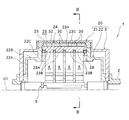
- FIG. 3 is a sectional view taken along line III-III in FIG. 2.
- FIG. 4 is a sectional view taken along line IV-IV in FIG. 3.
- It is a perspective view of the several bulk superconductor provided in the magnetic pole of the radial gap type superconducting synchronous machine shown in FIG.
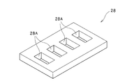
- It is a perspective view of the ferromagnetic material provided in the radial gap type superconducting synchronous machine shown in FIG.
- FIG. 1 is a perspective view of a magnetizing device according to an embodiment of the present invention, and is a view showing a part of the magnetizing device in cross section.
- FIG. FIG. 8 is a diagram illustrating the magnetizing device illustrated in FIG. 7, in which (A) is a longitudinal sectional view of the magnetizing device, and (B) is a diagram illustrating a part of magnetic flux lines generated by the magnetizing device. It is the figure which showed the graph explaining that the magnetic flux line at the time of magnetization of the magnetizing apparatus shown in FIG. 7 is collected effectively. It is a figure explaining a mode that it magnetizes with respect to the radial gap type superconducting synchronous machine shown in FIG. 1 with the magnetizing apparatus shown in FIG.
- FIG. 1 is a half sectional side view of a radial gap type superconducting synchronous machine 1.
- a radial gap type superconducting synchronous machine 1 includes a stator 10 having a circular cross section indicated by a two-dot chain line in FIG. 1, and a rotor 20 rotatably supported inside the stator 10. It is equipped with.
- the radial gap type superconducting synchronous machine 1 is a rotary field type synchronous machine.
- the stator 10 is provided with an armature coil (not shown), and the rotor 20 on the field side is provided with a magnetic pole 21. ing.
- the rotor 20 is fixed to a rotating shaft 2 that extends on a rotating shaft indicated by C1 in the drawing, and can rotate together with the rotating shaft 2 about the rotating shaft C1.
- a direction along the rotation axis C1 is referred to as a rotation axis C1 direction
- a direction orthogonal to the rotation axis C1 is referred to as a radial direction
- a direction around the rotation axis C1 is referred to as a circumferential direction.
- FIG. 2 is a view of the radial gap type superconducting synchronous machine 1 as viewed along the direction of the rotation axis C1.
- the rotor 20 includes a pair of disc portions 22A that are fixed to the rotary shaft 2 and extend in the radial direction, and a cylindrical body portion that connects between the outer peripheral edges of the disc portions 22A.
- the rotor main body 22 having 22B, the four convex magnetic poles 21 fixed to the outer peripheral portion of the body 22B of the rotor main body 22, and both ends covering the rotor main body 22 and the magnetic pole 21 in an airtight manner from the outside are closed.
- a substantially cylindrical vacuum cover 3 is a substantially cylindrical vacuum cover 3.
- each magnetic pole 21 is fixed to the tip of each magnetic pole fixing portion 22C.
- the rotor main body 22 of this Embodiment is mainly formed from the nonmagnetic stainless steel.
- the rotor main body 22 and the vacuum cover 3 are respectively fixed integrally to the rotary shaft 2, and the rotor main body 22 and the vacuum cover 3 can rotate around the rotation axis C ⁇ b> 1 together with the rotation shaft 2. Yes.
- the vacuum cover 3 is provided to insulate the rotor 20 from the outside by forming a vacuum heat insulating layer between the rotor body 22 and the magnetic pole 21.
- the vacuum cover 3 of the present embodiment is mainly formed from nonmagnetic stainless steel, but may be formed from an aluminum alloy or the like. Further, the vacuum cover 3 has a projecting protruding portion that covers the magnetic pole 21 on the outer peripheral portion thereof so as to cover each magnetic pole 21.
- the magnetic pole 21 of the present embodiment includes a rectangular plate-shaped cooling base member 23 fixed to the magnetic pole fixing portion 22 ⁇ / b> C in the rotor body 22, and the radial direction of the cooling base member 23.
- a bulk assembly 24, which is disposed outside and located on the tip end side of the magnetic pole 21, is composed of a plurality of bulk superconductors 30, and is disposed outside the bulk assembly 24 in the radial direction and is bulky between the cooling base member 23.
- a bulk fixing member 25 that sandwiches and fixes the aggregate 24.
- the cooling base member 23 of the present embodiment is formed of OFHC (Oxygen free high conductivity copper).
- an installation surface 23 ⁇ / b> A on which each bulk conductor 30 of the bulk assembly 24 is installed is formed on the radially outer surface of the cooling base member 23.
- the installation surface 23A has a center portion 23C located on the center side (center side of the magnetic pole 21) and side portions 23S located on both sides of the center portion 23C when viewed in the direction of the rotation axis C1.
- the portion 23C protrudes outward in the radial direction (on the stator 10 side) from the side portion 23S.
- the central portion 23C and the side portion 23S extend flat in the direction of the rotation axis C1.
- a connecting portion 23 ⁇ / b> B protruding inward in the radial direction is formed on the radially outer surface of the cooling base member 23.
- a heat transfer member 4 made of a copper material or the like is connected to each connection portion 23B. As shown in FIGS. 1 and 2, the heat transfer member 4 extends inward in the radial direction from the connection portion 23 ⁇ / b> B and is connected to the heat exchanger 5 installed at a portion covered with the rotor 20 in the rotary shaft 2. Has been.
- the heat exchanger 5 is supplied with a refrigerant such as neon that has passed through the rotary shaft 2, and the heat of the bulk assembly 24 is transferred from the cooling base member 23 through the heat transfer member 4. The heat is transmitted to the heat exchanger 5 and is absorbed by the heat exchanger 5. Thereby, each bulk conductor 30 of the bulk aggregate 24 installed in the cooling base member 23 can be maintained at a low temperature (superconducting transition temperature or lower).
- FIG. 5 is a perspective view of a plurality of bulk superconductors 30 constituting the bulk aggregate 24.
- the plurality of bulk superconductors 30 of the bulk assembly 24 are each formed in a rectangular shape when viewed from the outside in the radial direction, and in the radial direction The cross section is also formed in a rectangle.
- GdBCO GdBa2Cu3O7-z
- 15 bulk superconductors 30 are arranged on the installation surface 23A of the cooling base member 23 in three rows and five columns. That is, as shown in FIGS. 3 to 5, when viewed in the direction of the rotation axis C1, the central portion 23C and the side of the installation surface 23A of the cooling base member 23 are arranged so that three are arranged in the circumferential direction of the rotation axis C1.
- One bulk superconductor 30 is disposed in each of the portions 23S. Further, in the side view, five bulk superconductors 30 are arranged in the central portion 23C and the two side portions 23S so as to be arranged in the direction of the rotation axis C1. Adjacent bulk superconductors 30 are arranged in contact with each other, and the plurality of bulk superconductors 30 are concentrated at a high density.
- the bulk aggregate 24 in which the bulk superconductor 30 is arranged in this manner has a rectangular shape whose outline is long in the direction of the rotation axis C1.
- the central portion 23C projects outward from the side portion 23S in the radial direction (on the stator 10 side) on the installation surface 23A, so As seen, the bulk conductors 30 are arranged in a step shape. Thereby, the bulk superconductor 30 near the center of the magnetic pole 21 as viewed in the direction of the rotation axis C ⁇ b> 1 is arranged closer to the stator 10 than the other bulk superconductors 30.
- the bulk fixing member 25 is fixed to the magnetic pole fixing portion 22 ⁇ / b> C, and the bulk assembly 24 is sandwiched between the bulk fixing member 25 and the bulk superconductor 30 of the bulk assembly 24. Holding.
- the bulk fixing member 25 of the present embodiment is formed from a nonmagnetic material.
- the ferromagnetic body 28 is disposed on the rotation axis C1 side of the magnetic pole 21 (bulk assembly 24) configured as described above. As shown in FIGS. 3 and 4, the ferromagnetic body 28 is disposed in the state of being close to the cooling base member 23 of the magnetic pole 21.
- the magnetic body 28 of the present embodiment is formed of a ferromagnetic metal material mainly composed of iron.
- FIG. 6 is a perspective view of the magnetic body 28. As shown in FIG. 6, the ferromagnetic body 28 is formed in a rectangular plate shape, and a through hole 28 ⁇ / b> A for allowing the heat transfer member 4 to pass therethrough is formed.
- the ferromagnetic body 28 is disposed close to the cooling base member 23 with the heat transfer member 4 inserted into the through hole 28A, and is fixed to the magnetic pole fixing portion 22C. Further, the ferromagnetic body 28 has a size larger than that of the bulk aggregate 24 when viewed along the radial direction, and is disposed so as to cover the entire area of the bulk aggregate 24 from the inside.
- each bulk superconductor 30 of the bulk assembly 24 is magnetized by a magnetizing device 100 described later.
- the ferromagnetic body 28 can guide the magnetic flux lines from the magnetizing apparatus 100 so as to pass through the bulk assembly 24, and after the magnetization on the bulk assembly 24, the bulk assembly 24. Can be stably maintained at the intended installation position. Details of this will be described later.
- the magnetizing apparatus 100 is used when magnetizing each bulk superconductor 30 of the bulk assembly 24 of the radial gap type superconducting synchronous machine 1 described above.
- 7 is a perspective view of the magnetizing device 100
- FIG. 8A is a longitudinal sectional view of the magnetizing device 100
- FIG. 8B is a part of the magnetic flux lines generated by the magnetizing device 100.
- the magnetizing apparatus 100 includes a top wall portion 101T, a peripheral wall portion 101S depending from the outer peripheral portion of the top wall portion 101T, and an inner side of the peripheral wall portion 101S. And a core 101C hanging from the inner surface of the top wall 101T.
- the housing 101 is made of a ferromagnetic metal material mainly composed of iron.
- the core portion 101C is located in an intermediate region between the peripheral wall portions 101S facing each other in a cross-sectional view.
- the peripheral wall portion 101S is open in the direction opposite to the top wall portion 101T side.
- a superconducting coil (hereinafter simply referred to as a coil) 102 is accommodated while being wound around the core portion 101C and covered with the top wall portion 101T and the peripheral wall portion 101S.
- the coil 102 is made of a superconducting material (in this embodiment, Bi2233 (Bi2Sr2Ca2Cu3O10 + ⁇ )), and is connected to the current supply unit 104 via a connection line 103 drawn out of the housing 101.
- a current is supplied from the current supply unit 104 to the coil 102, a magnetic field is generated from the coil 102.
- the outline of the housing 101 is formed in a substantially rectangular shape, and the core portion 101C is formed in a long shape extending along the longitudinal direction of the housing 101.
- the length in the longitudinal direction of the core portion 101C is equal to the length in the direction of the rotation axis C1 of the bulk assembly 24 of the radial gap type superconducting synchronous machine 1 described above with reference to FIG.
- the outline of the coil 102 wound around the core portion 101C is also formed in a substantially rectangular shape.
- the coil 102 is formed by winding a conducting wire in a substantially rectangular shape in multiple layers.
- the housing 101 will be described in detail. As shown in FIG. 8A, the height from the top wall portion 101T of the peripheral wall portion 101S is larger than the height from the top wall portion 101T of the core portion 101C. Further, in the present embodiment, the peripheral wall portion 101S integrally has a bottom wall portion 101E extending from the tip portion toward the core portion 101C side. In the present embodiment, since the bottom wall portion 101E is formed integrally with the peripheral wall portion 101S, the bottom wall portion 101E is also a ferromagnetic material.
- the bottom wall portion 101E extends to a position that does not overlap the core portion 101C when viewed along the direction in which the core portion 101C hangs (projects). Then, in the region facing the tip portion of the core portion 101C in the direction in which the core portion 101C hangs down (protrudes) and located on the inner side of the inner peripheral edge of the bottom wall portion 101E, the space in which the magnetic object is arranged D is formed. Specifically, in this embodiment, since the object to be magnetized is the bulk assembly 24 of the magnetic poles 21 of the radial gap superconducting synchronous machine 1, the bottom wall 101E has the magnetic poles 21 inside the inner peripheral edge. It is inserted and formed so that the bulk aggregate 24 can be positioned in the arrangement space D.
- the coil 102 is covered by the top wall portion 101T and the peripheral wall portion 101S of the housing 101 made of a ferromagnetic material, and the peripheral wall portion 101S is in a direction opposite to the top wall portion 101T side.
- a magnetic circuit that flows through is formed.
- the height from the top wall part 101T of the surrounding wall part 101S is larger than the height from the top wall part 101T of the core part 101C, as shown in FIG.
- FIG. 9 shows that the magnetic flux lines at the time of magnetization of the magnetizing device 100 are effectively aggregated, that is, the total magnetic flux generated by the magnetizing device 100 for the magnetized device is effectively secured.
- the graph explaining is shown.
- the total magnetic flux generated by the magnetizing device (comparative device) in which the portion corresponding to the housing 101 in the magnetizing device 100 is formed of an aluminum alloy that is not a ferromagnetic material is generated by the magnetizing device 100.
- the result of comparing the total magnetic flux to be generated is shown.
- the total magnetic flux is the total amount of magnetic flux in the entire arrangement space D.
- the total magnetic flux generated by the magnetizing device 100 greatly exceeds the total magnetic flux generated by the comparison target device. Specifically, in this graph, compared to the comparison target device. Thus, the total magnetic flux of the magnetizing device 100 is increased by about 27%.
- FIG. 10 is a diagram for explaining the state of magnetization.
- the magnetizing device 100 When magnetization is performed by the magnetizing device 100, first, the rotor 20 of the radial gap type superconducting synchronous machine 1 is taken out of the stator 10. After that, as shown in FIG. 10, the magnetic pole 21 of the rotor 20 is inserted into the arrangement space D of the magnetizing device 100, and the bulk aggregate 24 of the magnetic pole 21 approaches the core portion 101 ⁇ / b> C in the arrangement space D.
- the magnetizing device 100 is disposed outside the magnetic pole 21 in the radial direction so as to face each other.
- the bulk aggregate 24 is located in the arrangement space D on the core portion 101C side with respect to the inner surface of the bottom wall portion 101E of the housing 101, and the radial gap type superconducting synchronous machine 1
- the magnetizing device 100 is arranged so that the ferromagnetic body 28 is positioned closer to the core portion 101C than the outer surface of the bottom wall portion 101E.
- the magnetic pole 21 of the rotor 20 is inserted into the arrangement space D by lowering the magnetizing device 100.
- An overhanging portion that covers the magnetic pole 21 in the vacuum cover 3 is also arranged in the arrangement space D.
- magnetization is performed by directing the magnetic flux line of the magnetizing apparatus 100 from the front-end
- FIG. In the present embodiment, magnetization is performed by static magnetic field magnetization by continuously supplying current to the coil 102.
- FIG. 11 is a graph illustrating an example of temperature control and magnetic field application timing for the bulk superconductor during magnetization according to the present embodiment.
- time is shown on the horizontal axis
- the temperature (K) of the bulk superconductor 30 and the magnetic flux density (T) of the applied magnetic field are shown on the vertical axis.
- a line L1 indicates a temperature state of the bulk superconductor 30 and a line L2 indicates a magnetic flux density state of a magnetic field generated by supplying a current to the coil 102.
- Tc represents the superconducting transition temperature.
- a static magnetic field (steady magnetic field) with respect to the bulk superconductor 30 is controlled so that the temperature of the bulk superconductor 30 is higher than the superconducting transition temperature Tc. Is started. Then, after the magnetic flux density of the static magnetic field reaches a predetermined target value, the temperature of the bulk superconductor 30 is lowered while the target value is maintained, and a predetermined temperature (not shown) lower than the superconducting transition temperature Tc. In the example, 50K) is reached. At this time, the bulk superconductor 30 enters a superconducting state from the superconducting transition temperature Tc, and the magnetic flux lines pass through the bulk superconductor 30. In the graph of FIG.
- the magnetic field is applied for a predetermined time (in the example shown, about 60 minutes) until the bulk superconductor 30 reaches a predetermined temperature lower than the superconducting transition temperature Tc.
- a predetermined time in the example shown, about 60 minutes
- Tc superconducting transition temperature
- the magnetic flux density on the one end extension line of the core part 101C in the arrangement space D can be effectively ensured.
- the magnetic flux lines from the magnetizing apparatus 100 pass through the bulk assembly 24 as shown in FIG. Thus, it is guided to reach the ferromagnetic body 28.
- the housing of the magnetizing device 100 and the ferromagnetic body 28 are substantially rectangular. Are formed, and the bulk assembly 24 is positioned in a straight line portion of the magnetic circuit, so that the magnetic flux lines efficiently pass through the bulk assembly 24. Thereby, magnetization is performed efficiently.
- the supply of current to the coil 102 is stopped, that is, the applied current of the coil 102 is set to 0, and the magnetic field Is resolved.
- the rotor 20 is rotated, the magnetic pole 21 to be magnetized next to the rotor 20 is arranged in the arrangement space D of the magnetizing device 100, and magnetization is performed.
- the coil 102 is covered with the top wall 101T and the peripheral wall 101S of the housing 101 made of a ferromagnetic material, and the peripheral wall 101S is on the opposite side of the top wall 101T side.
- the peripheral wall 101S is formed by opening in the direction, one end portion (tip portion) of the core portion 101C ⁇ bottom wall portion 101E ⁇ circumferential wall portion 101S ⁇ top wall portion 101T ⁇ the other end portion (base end portion) of the core portion 101C.
- a magnetic circuit that flows through is formed.
- the peripheral wall portion 101S has a height from the top wall portion 101T that is higher than the height from the top wall portion 101T of the core portion 101C, so that the peripheral wall portion 101S extends from one end (tip) of the core portion 101C.
- Magnetic flux lines W in the magnetic circuit reaching (bottom wall portion 101E) are concentrated (concentrated) in the arrangement space D inside the peripheral wall portion 101S and the bottom wall portion 101E. Thereby, the magnetic flux density on the one end extension line of the core part 101C in the arrangement space D can be effectively ensured. Thereby, a high-density magnetic flux can pass through the adherend on the one end extension line of the core portion 101C in the arrangement space D.
- the peripheral wall portion 101S has a bottom wall portion 101E made of a ferromagnetic material that extends from the tip portion toward the core portion 101C, and the bottom wall portion 101E is suspended from the core portion 101C.
- the arrangement space D is a region facing the tip of the core portion 101C and inside the inner peripheral edge of the bottom wall portion 101E. It is formed in the region located in Thereby, the magnetic flux lines W are further concentrated (concentrated) on the extension line of the one end part of the core part 101C in the arrangement space D by reaching the bottom wall part 101E from the one end part (tip part) of the core part 101C. The Thereby, the efficiency of the magnetization with respect to a to-be-magnetized object is improved further.
- the ferromagnetic body 28 since the ferromagnetic body 28 is provided, a large number of magnetic flux lines W from the magnetizing device 100 pass through the bulk assembly 24 including the bulk superconductor 30. It is guided to reach the ferromagnetic body 28. As a result, the magnetic flux lines can be aggregated and passed through the bulk assembly 24 composed of the bulk superconductor 30.
- the magnetizing apparatus 100 of the present embodiment can secure a sufficient trapping magnetic flux in the bulk assembly 24 even when the coil 102 is separated from the bulk assembly 24, the trapping magnetic flux sufficient for the bulk assembly 24 is sufficient.
- the degree of freedom of arrangement that can ensure the above is improved, and the practicality can be ensured also in this respect.
- the magnetizing device 100 is disposed close to the bulk assembly 24 of the magnetic poles 21 to be magnetized. Even so, since the magnetizing apparatus 100 is prevented from interfering with the adjacent magnetic poles, it is possible to secure a sufficient trapped magnetic flux in each of the plurality of magnetic poles arranged.
- the bulk assembly 24 is fixed in the central part side of the magnetic pole 21 as compared with the end part side when viewed in the direction of the rotation axis C1 of the rotor 20. It is arranged close to the child 10. As a result, the bulk assembly 24 is disposed along the arcuate inner surface of the stator 10, and the gap between the bulk assembly 24 and the stator 10 can be suppressed. As a result, a magnetic field can be efficiently applied from the bulk assembly 24 toward the stator 10.
- the magnetized bulk assembly 24 when the bulk assembly 24 is magnetized by the magnetizing device 100, the magnetized bulk assembly 24 is magnetized by the magnetic force. While trying to move toward the housing 101 made of a ferromagnetic material constituting the device 100, it also tries to move toward the ferromagnetic material 28 on the rotation axis C 1 side of the bulk aggregate 24. Thereby, the bulk aggregate 24 can be held at an intended installation position by suppressing the bulk aggregate 24 from moving toward the magnetizing device 100.
- FIG. 13 is a table summarizing the performance of the radial gap type superconducting synchronous machine 1 according to the embodiment of the present invention and the performances of the conventional superconducting synchronous machines according to Comparative Examples 1 to 3.
- FIG. 13 the “model” of the synchronous machine of the example and comparative examples 1 to 3, “rotation speed”, “torque” and “output” indicating an example of performance, and “field” or “armature” “Superconducting material”, “refrigerant” or “cooling system” for maintaining the superconducting material at a low temperature, and “capture magnetic flux density” at the magnetic pole are shown.
- the magnetic flux is captured by the bulk aggregate 24 of each magnetic pole 21 by being magnetized by the magnetizing device 100 as described in the above embodiment. It is.
- GdBCO is used for the bulk superconductor 30 and neon is used for the refrigerant.
- an extremely high magnetic flux density of 5.0 Tesla (T) is obtained as an example of the trapped magnetic flux, and an extremely high torque of 1508 Nm is obtained when the rotational speed is 190 rpm. It is estimated that And the output at the time of this rotation speed is estimated with 30 kW.
- Comparative Example 1 is a reluctance type superconducting synchronous machine (radial gap type) in which YBCO (YBa2Cu3O7-z) high-temperature superconducting bulk is used for the field pole and liquid nitrogen is used for the refrigerant.
- YBCO YBa2Cu3O7-z
- An example of the performance shows that a torque of 127 Nm is obtained at 3000 rpm, and the output at this time is 40 kW.
- an extremely large torque is obtained in the low rotation range as compared with the comparative example 1, so that a large output can be obtained more quickly than the comparative example 1. I understand.
- Comparative Example 2 is a radial gap type superconducting synchronous machine in which a YBCO high-temperature superconducting bulk is used for the field pole and direct conduction cooling is used for cooling. As an example of the performance, it is shown that a torque of 24 Nm is obtained at 600 rpm, and the output at this time is 1.5 kW. Comparing the example and the comparative example 2, in the example, an extremely large torque is obtained compared to the comparative example 2 in the low rotation range, so that a much larger output can be obtained more quickly than the comparative example 2. I understand that
- Comparative Example 3 is an axial gap type superconducting synchronous machine, the superconducting material GdBCO is used for the field, the trapped magnetic flux density is 0.8 to 0.9 T, and the liquid nitrogen is used for the refrigerant. Is. As an example of the performance, it is shown that a torque of 212 Nm is obtained at 720 rpm, and the output at this time is 16 kW. Comparing the example and the comparative example 3, the comparative example 3 can obtain a high torque at a relatively low rotation, but does not reach the example. For this reason, in an Example, it turns out that a much bigger output is obtained quicker than the comparative example 3. FIG. In Comparative Example 3, the bulk superconductor is magnetized by pulse magnetization.
- the stator 10 is formed in a cylindrical shape having a circular cross section and a relatively long axial direction, but a relatively short annular shape in the axial direction. It may be formed.
- the stator 10 is preferably formed in an annular shape.
- the material for forming the rotor 20 and the vacuum cover 3 may be a material other than that described in the embodiment.
- the bulk superconductor 30 of the embodiment has been described as having a rectangular shape when viewed from the outside in the radial direction of the rotor 20, but may be a circular one or the like.
- the bulk superconductor 30 is provided in the radial gap type superconducting synchronous machine 1, but a superconducting wire may be provided.
- the bottom wall 101E provided in the magnetizing device 100 may not be provided in the housing 100, but when the bottom wall 101E is provided, the efficiency of magnetization is improved.
Landscapes
- Engineering & Computer Science (AREA)
- Power Engineering (AREA)
- Manufacturing & Machinery (AREA)
- Superconductive Dynamoelectric Machines (AREA)
- Permanent Field Magnets Of Synchronous Machinery (AREA)
Abstract
Description
断面円形状の固定子の内側に回転子を回転可能に支承するようにし、前記回転子の外周側に超電導体を配置したラジアルギャップ型超電導同期機において、
前記回転子は、回転シャフトに固定された回転子本体と、当該回転子本体の外周部に設けられた凸状の磁極を有し、
前記磁極の先端部は、前記超電導体を有し、
前記超電導体は、前記回転子の回転軸方向に見て、前記磁極中央部側が端部側に比して前記固定子に近接して配置され、
前記超電導体の前記回転子の回転軸側には、強磁性体が配置されていることを特徴とする。
前記超電導体は、前記磁極の先端部において複数配置されており、
複数の前記超電導体は、前記回転子の回転軸方向に見て、前記磁極中央部に近い超電導体が他の超電導体よりも前記固定子に近接して配置されるように、ひな段状に配置されていることが好ましい。
前記超電導体は、前記回転子の径方向の外側から見て矩形であることが好ましい。
前記超電導体は、前記磁極の先端部において複数配置されており、
複数の前記超電導体は、前記磁極の先端部において、前記回転子の周方向に並んで配置されると共に前記回転子の回転軸方向に並んで配置されていることが好ましい。
頂壁部と、前記頂壁部の外周部から垂下する周壁部と、前記周壁部の内側において前記頂壁部の内面から垂下するコア部と、を有する強磁性体からなるハウジングと、
前記コア部の周囲に巻き回されると共に、前記頂壁部及び前記周壁部によって覆われる状態で、前記ハウジング内に収容されるコイルと、
前記コイルに電流を供給する電流供給部と、を備え、
前記周壁部は、前記頂壁部側とは反対側の方向に向けて開放し、前記周壁部の前記頂壁部からの高さは、前記コア部の前記頂壁部からの高さよりも大きくなっており、
前記コア部の先端部に対向する領域であって、前記周壁部の内側に位置する領域に、被着磁物の配置空間が形成されていることを特徴とする。
前記周壁部は、その先端部から前記コア部側に向けて延びる、強磁性体からなる底壁部を有し、
前記底壁部は、前記コア部が垂下する方向に沿って見た場合に、前記コア部と重ならない位置まで延びており、
前記配置空間は、前記コア部の先端部に対向する領域であって、前記底壁部の内周縁の内側に位置する領域に形成されていることが好ましい。
断面円形状の固定子の内側に回転子を回転可能に支承するようにし、前記回転子の外周側に超電導体を配置したラジアルギャップ型超電導同期機の着磁方法において、
前記回転子が、回転シャフトに固定された回転子本体と、当該回転子本体の外周部に設けられた凸状の磁極を有し、前記磁極の先端部が、前記超電導体を有し、前記超電導体が、前記回転子の回転軸方向に見て、前記磁極中央部側が端部側に比して前記固定子に近接して配置され、前記超電導体の前記回転子の回転軸側には強磁性体が配置されている、前記ラジアルギャップ型超電導同期機を、準備する工程と、
前記超電導体の前記回転子の径方向の外側に、着磁装置を配置する工程と、
前記着磁装置からの磁束線を前記超電導体に向けて着磁を行う工程と、を有することを特徴とする。
前記着磁装置を配置する工程においては、
前記着磁装置の前記配置空間内に前記ラジアルギャップ型超電導同期機の前記超電導体が位置するように、前記着磁装置が配置されることが好ましい。
断面円形状の固定子の内側に回転子を回転可能に支承するようにし、前記回転子の外周側に超電導体を配置したラジアルギャップ型超電導同期機の着磁方法において、
頂壁部と、前記頂壁部の外周部から垂下する周壁部と、前記周壁部の内側において前記頂壁部の内面から垂下するコア部と、を有する強磁性体からなるハウジングと、前記コア部の周囲に巻き回されると共に、前記頂壁部及び前記周壁部によって覆われる状態で、前記ハウジング内に収容されるコイルと、前記コイルに電流を供給する電流供給部と、を備え、前記周壁部は、前記頂壁部側とは反対側の方向に向けて開放し、前記周壁部の前記頂壁部からの高さは、前記コア部の前記頂壁部からの高さよりも大きくなっており、前記コア部の先端部に対向する領域であって、前記周壁部の内側に位置する領域に、被着磁物の配置空間が形成されている、着磁装置を、準備する工程と、
前記着磁装置の前記配置空間内に前記ラジアルギャップ型超電導同期機の前記超電導体が位置し、且つ前記着磁装置の前記コア部の先端部を前記超電導体に向けた状態で、前記超電導体の前記回転子の径方向の外側に、前記着磁装置を配置する工程と、
前記着磁装置からの磁束線を前記超電導体に向けて着磁を行う工程と、を有する
ことを特徴とする。
前記着磁装置を配置する工程においては、
前記着磁装置の前記配置空間内において前記超電導体が前記底壁部よりも前記コア部側に位置するように、前記着磁装置が配置されることが好ましい。
前記超電導体の温度が超電導転移温度よりも高い温度となる状況下で、前記超電導体に対する静磁場の印加を開始し、磁束密度が所定の目標値に到達された後、その目標値が保持されながら、前記超電導体の温度が前記超電導転移温度よりも低い所定の温度まで降下され、その後、前記着磁装置により印加された磁場が解消されてもよい。
これにより、配置空間におけるコア部の一端部延長線上において高密度の磁束を被着磁物に通過させることができることで、被着磁物から着磁装置のコイルが離れて配置されて被着磁物を囲うようにコイルが大きく形成されなくても、被着磁物に対する着磁が高効率に行われる。これにより、大型にしなくても被着磁物における十分な捕捉磁束を確保できるため、結果的に、実用性を確保しつつ、被着磁物における捕捉磁束を効果的に増加させることができる。
これにより、配置空間におけるコア部の一端部延長線上での磁束密度を効果的に確保することができる。
これにより、配置空間におけるコア部の一端部延長線上において高密度の磁束を被着磁物に通過させることができることで、被着磁物から着磁装置のコイルが離れて配置されて被着磁物を囲うようにコイルが大きく形成されなくても、被着磁物に対する着磁が高効率に行われる。これにより、大型にしなくても被着磁物における十分な捕捉磁束を確保できるため、結果的に、実用性を確保しつつ、被着磁物における捕捉磁束を効果的に増加させることができる。
本発明の実施の形態によるラジアルギャップ型超電導同期機1について先ず説明する。図1は、ラジアルギャップ型超電導同期機1の半断面側面図である。
次に、本実施の形態による着磁装置100について説明する。当該着磁装置100は、上述したラジアルギャップ型超電導同期機1のバルク集合体24の各バルク超電導体30に対する着磁の際に用いられる。図7は、着磁装置100の斜視図であり、図8(A)は着磁装置100の縦断面図であり、図8(B)は着磁装置100によって発生された磁束線の一部を示した図である。
次に、前述したラジアルギャップ型超電導同期機1に対して前述した着磁装置100により着磁を行う着磁方法について説明する。図10は、着磁の様子を説明する図である。
次に、本発明の実施例によるラジアルギャップ型超電導同期機1について説明する。図13は、本発明の実施例によるラジアルギャップ型超電導同期機1の性能と、比較例1~3による従来の超電導同期機の各性能と、をまとめた表を示す図である。
例えば、実施の形態のラジアルギャップ型超電導同期機1では、バルク集合体24が15個のバルク超電導体30から構成される例を説明したが、バルク超電導体30の数は他の態様であってもよいし、1つのバルク超電導体が磁極部21に設けられてもよい。また、バルク超電導体30の材料はGdBCOに限定されるものではない。
2 回転シャフト
3 真空カバー
4 伝熱部材
5 熱交換器
10 固定子
20 回転子
21 磁極
22 回転子本体
22A 円板部
22B 胴部
22C 磁極固定部
23 冷却ベース部材
23A 設置面
23B 接続部
23C 中央部
23S 側部
24 バルク集合体
25 バルク固定部材
28 強磁性体
30 バルク超電導体
100 着磁装置
101 ハウジング
101T 頂壁部
101S 周壁部
101C コア部
101E 底壁部
102 コイル
103 接続線
104 電流供給部
Claims (13)
- 断面円形状の固定子の内側に回転子を回転可能に支承するようにし、前記回転子の外周側に超電導体を配置したラジアルギャップ型超電導同期機において、
前記回転子は、回転シャフトに固定された回転子本体と、当該回転子本体の外周部に設けられた凸状の磁極を有し、
前記磁極の先端部は、前記超電導体を有し、
前記超電導体は、前記回転子の回転軸方向に見て、前記磁極中央部側が端部側に比して前記固定子に近接して配置され、
前記超電導体の前記回転子の回転軸側には、強磁性体が配置されている
ことを特徴とするラジアルギャップ型超電導同期機。 - 前記超電導体は、前記磁極の先端部において複数配置されており、
複数の前記超電導体は、前記回転子の回転軸方向に見て、前記磁極中央部に近い超電導体が他の超電導体よりも前記固定子に近接して配置されるように、ひな段状に配置されている
ことを特徴とする請求項1に記載のラジアルギャップ型超電導同期機。 - 前記超電導体は、前記回転子の径方向の外側から見て矩形である
ことを特徴とする請求項1に記載のラジアルギャップ型超電導同期機。 - 前記超電導体は、前記磁極の先端部において複数配置されており、
複数の前記超電導体は、前記磁極の先端部において、前記回転子の周方向に並んで配置されると共に前記回転子の回転軸方向に並んで配置されている
ことを特徴とする請求項1に記載のラジアルギャップ型超電導同期機。 - 頂壁部と、前記頂壁部の外周部から垂下する周壁部と、前記周壁部の内側において前記頂壁部の内面から垂下するコア部と、を有する強磁性体からなるハウジングと、
前記コア部の周囲に巻き回されると共に、前記頂壁部及び前記周壁部によって覆われる状態で、前記ハウジング内に収容されるコイルと、
前記コイルに電流を供給する電流供給部と、を備え、
前記周壁部は、前記頂壁部側とは反対側の方向に向けて開放し、前記周壁部の前記頂壁部からの高さは、前記コア部の前記頂壁部からの高さよりも大きくなっており、
前記コア部の先端部に対向する領域であって、前記周壁部の内側に位置する領域に、被着磁物の配置空間が形成されている
ことを特徴とする着磁装置。 - 前記周壁部は、その先端部から前記コア部側に向けて延びる、強磁性体からなる底壁部を有し、
前記底壁部は、前記コア部が垂下する方向に沿って見た場合に、前記コア部と重ならない位置まで延びており、
前記配置空間は、前記コア部の先端部に対向する領域であって、前記底壁部の内周縁の内側に位置する領域に形成されている
ことを特徴とする請求項5に記載の着磁装置。 - 断面円形状の固定子の内側に回転子を回転可能に支承するようにし、前記回転子の外周側に超電導体を配置したラジアルギャップ型超電導同期機の着磁方法において、
前記回転子が、回転シャフトに固定された回転子本体と、当該回転子本体の外周部に設けられた凸状の磁極を有し、前記磁極の先端部が、前記超電導体を有し、前記超電導体が、前記回転子の回転軸方向に見て、前記磁極中央部側が端部側に比して前記固定子に近接して配置され、前記超電導体の前記回転子の回転軸側には強磁性体が配置されている、前記ラジアルギャップ型超電導同期機を、準備する工程と、
前記超電導体の前記回転子の径方向の外側に、着磁装置を配置する工程と、
前記着磁装置からの磁束線を前記超電導体に向けて着磁を行う工程と、を有する
ことを特徴とする着磁方法。 - 前記着磁装置は、頂壁部と、前記頂壁部の外周部から垂下する周壁部と、前記周壁部の内側において前記頂壁部の内面から垂下するコア部と、を有する強磁性体からなるハウジングと、前記コア部の周囲に巻き回されると共に、前記頂壁部及び前記周壁部によって覆われる状態で、前記ハウジング内に収容されるコイルと、前記コイルに電流を供給する電流供給部と、を備え、前記周壁部は、前記頂壁部側とは反対側の方向に向けて開放し、前記周壁部の前記頂壁部からの高さは、前記コア部の前記頂壁部からの高さよりも大きくなっており、前記コア部の先端部に対向する領域であって、前記周壁部の内側に位置する領域に、被着磁物の配置空間が形成されている、着磁装置であり、
前記着磁装置を配置する工程においては、
前記着磁装置の前記配置空間内に前記ラジアルギャップ型超電導同期機の前記超電導体が位置するように、前記着磁装置が配置される
ことを特徴とする請求項7に記載の着磁方法。 - 前記着磁装置において、前記周壁部は、その先端部から前記コア部側に向けて延びる、強磁性体からなる底壁部を有し、前記底壁部は、前記コア部が垂下する方向に沿って見た場合に、前記コア部と重ならない位置まで延びており、前記配置空間は、前記コア部の先端部に対向する領域であって、前記底壁部の内周縁の内側に位置する領域に形成されており、
前記着磁装置を配置する工程においては、
前記着磁装置の前記配置空間内において前記超電導体が前記底壁部よりも前記コア部側に位置するように、前記着磁装置が配置される
ことを特徴とする請求項8に記載の着磁方法。 - 断面円形状の固定子の内側に回転子を回転可能に支承するようにし、前記回転子の外周側に超電導体を配置したラジアルギャップ型超電導同期機の着磁方法において、
頂壁部と、前記頂壁部の外周部から垂下する周壁部と、前記周壁部の内側において前記頂壁部の内面から垂下するコア部と、を有する強磁性体からなるハウジングと、前記コア部の周囲に巻き回されると共に、前記頂壁部及び前記周壁部によって覆われる状態で、前記ハウジング内に収容されるコイルと、前記コイルに電流を供給する電流供給部と、を備え、前記周壁部は、前記頂壁部側とは反対側の方向に向けて開放し、前記周壁部の前記頂壁部からの高さは、前記コア部の前記頂壁部からの高さよりも大きくなっており、前記コア部の先端部に対向する領域であって、前記周壁部の内側に位置する領域に、被着磁物の配置空間が形成されている、着磁装置を、準備する工程と、
前記着磁装置の前記配置空間内に前記ラジアルギャップ型超電導同期機の前記超電導体が位置し、且つ前記着磁装置の前記コア部の先端部を前記超電導体に向けた状態で、前記超電導体の前記回転子の径方向の外側に、前記着磁装置を配置する工程と、
前記着磁装置からの磁束線を前記超電導体に向けて着磁を行う工程と、を有する
ことを特徴とする着磁方法。 - 前記着磁装置において、前記周壁部は、その先端部から前記コア部側に向けて延びる、強磁性体からなる底壁部を有し、前記底壁部は、前記コア部が垂下する方向に沿って見た場合に、前記コア部と重ならない位置まで延びており、前記配置空間は、前記コア部の先端部に対向する領域であって、前記底壁部の内周縁の内側に位置する領域に形成されており、
前記着磁装置を配置する工程においては、
前記着磁装置の前記配置空間内において前記超電導体が前記底壁部よりも前記コア部側に位置するように、前記着磁装置が配置される
ことを特徴とする請求項10に記載の着磁方法。 - 前記着磁を行う工程においては、
前記超電導体の温度が超電導転移温度よりも高い温度となる状況下で、前記超電導体に対する静磁場の印加を開始し、磁束密度が所定の目標値に到達された後、その目標値が保持されながら、前記超電導体の温度が前記超電導転移温度よりも低い所定の温度まで降下され、その後、前記着磁装置により印加された磁場が解消される
ことを特徴とする請求項7に記載の着磁方法。 - 前記着磁を行う工程においては、
前記超電導体の温度が超電導転移温度よりも高い温度となる状況下で、前記超電導体に対する静磁場の印加を開始し、磁束密度が所定の目標値に到達された後、その目標値が保持されながら、前記超電導体の温度が前記超電導転移温度よりも低い所定の温度まで降下され、その後、前記着磁装置により印加された磁場が解消される
ことを特徴とする請求項10に記載の着磁方法。
Priority Applications (4)
| Application Number | Priority Date | Filing Date | Title |
|---|---|---|---|
| JP2016510432A JP6566483B2 (ja) | 2014-03-28 | 2015-03-25 | ラジアルギャップ型超電導同期機、着磁装置、及び着磁方法 |
| EP15769533.9A EP3125415B1 (en) | 2014-03-28 | 2015-03-25 | Radial-gap-type superconducting synchronous machine, magnetization device, and magnetization method |
| US15/300,220 US10594197B2 (en) | 2014-03-28 | 2015-03-25 | Radial-gap type superconducting synchronous machine, magnetizing apparatus and magnetizing method |
| US16/786,673 US11502590B2 (en) | 2014-03-28 | 2020-02-10 | Radial-gap type superconducting synchronous machine, magnetizing apparatus, and magnetizing method |
Applications Claiming Priority (2)
| Application Number | Priority Date | Filing Date | Title |
|---|---|---|---|
| JP2014069925 | 2014-03-28 | ||
| JP2014-069925 | 2014-03-28 |
Related Child Applications (2)
| Application Number | Title | Priority Date | Filing Date |
|---|---|---|---|
| US15/300,220 A-371-Of-International US10594197B2 (en) | 2014-03-28 | 2015-03-25 | Radial-gap type superconducting synchronous machine, magnetizing apparatus and magnetizing method |
| US16/786,673 Division US11502590B2 (en) | 2014-03-28 | 2020-02-10 | Radial-gap type superconducting synchronous machine, magnetizing apparatus, and magnetizing method |
Publications (1)
| Publication Number | Publication Date |
|---|---|
| WO2015147068A1 true WO2015147068A1 (ja) | 2015-10-01 |
Family
ID=54195579
Family Applications (1)
| Application Number | Title | Priority Date | Filing Date |
|---|---|---|---|
| PCT/JP2015/059155 Ceased WO2015147068A1 (ja) | 2014-03-28 | 2015-03-25 | ラジアルギャップ型超電導同期機、着磁装置、及び着磁方法 |
Country Status (4)
| Country | Link |
|---|---|
| US (2) | US10594197B2 (ja) |
| EP (1) | EP3125415B1 (ja) |
| JP (1) | JP6566483B2 (ja) |
| WO (1) | WO2015147068A1 (ja) |
Cited By (2)
| Publication number | Priority date | Publication date | Assignee | Title |
|---|---|---|---|---|
| WO2017167479A1 (de) * | 2016-03-30 | 2017-10-05 | Siemens Aktiengesellschaft | Elektrische maschine mit supraleitfähigem permanentmagneten und verfahren zum magnetisieren des permanentmagneten |
| JP2019161738A (ja) * | 2018-03-08 | 2019-09-19 | 三菱重工業株式会社 | 超電導回転機械用かご型ロータ、超電導回転機械用ステータ、及び超電導回転機械 |
Families Citing this family (4)
| Publication number | Priority date | Publication date | Assignee | Title |
|---|---|---|---|---|
| DE102018215917A1 (de) * | 2018-08-21 | 2020-02-27 | Siemens Aktiengesellschaft | Rotor mit Rotorwicklung für Betrieb im Dauerstrommodus |
| DE102018216890A1 (de) * | 2018-10-02 | 2020-04-02 | Rolls-Royce Deutschland Ltd & Co Kg | Rotor und Maschine mit supraleitendem Permanentmagneten |
| DE102018217983A1 (de) * | 2018-10-22 | 2020-04-23 | Rolls-Royce Deutschland Ltd & Co Kg | Rotor und Maschine mit supraleitendem Permanentmagneten in einem Rotorträger |
| CN114498970B (zh) * | 2022-03-02 | 2023-12-01 | 北京交通大学 | 一种超导同步电机充磁结构及方法 |
Citations (3)
| Publication number | Priority date | Publication date | Assignee | Title |
|---|---|---|---|---|
| JPH05219717A (ja) * | 1992-02-07 | 1993-08-27 | Mitsubishi Heavy Ind Ltd | 超電導モータ |
| JP2003332128A (ja) * | 2002-05-15 | 2003-11-21 | Toshiba Corp | 磁石製造用金型装置,磁石の製造方法,異方性磁石及び永久磁石モータ |
| JP2008034692A (ja) * | 2006-07-31 | 2008-02-14 | Aisin Seiki Co Ltd | 超電導体、超電導磁場発生素子、超電導磁場発生装置および核磁気共鳴装置 |
Family Cites Families (13)
| Publication number | Priority date | Publication date | Assignee | Title |
|---|---|---|---|---|
| JPS5142285B1 (ja) * | 1969-10-09 | 1976-11-15 | ||
| JPH02111238A (ja) | 1988-10-17 | 1990-04-24 | Fanuc Ltd | 永久磁石形同期電動機 |
| US5177054A (en) * | 1991-04-08 | 1993-01-05 | Emerson Electric Co. | Flux trapped superconductor motor and method therefor |
| US6111490A (en) * | 1996-06-19 | 2000-08-29 | Aisin Seiki Kabushiki Kaisha | Superconducting magnet apparatus and method for magnetizing superconductor |
| US7453174B1 (en) * | 1999-08-10 | 2008-11-18 | American Superconductor Corporation | Superconducting electric motor |
| US6707209B2 (en) | 2000-12-04 | 2004-03-16 | Emerson Electric Co. | Reduced cogging torque permanent magnet electric machine with rotor having offset sections |
| US7750524B2 (en) * | 2003-01-09 | 2010-07-06 | University Of Fukui | Superconductor magnetizing device and superconducting synchronization device |
| JP4152898B2 (ja) | 2003-01-09 | 2008-09-17 | 国立大学法人福井大学 | バルク超電導体の着磁装置、着磁方法及び超電導同期機 |
| DE10335040B4 (de) * | 2003-08-01 | 2009-09-03 | Siemens Ag | Elektrische Maschine mit ferromagnetischem Polkern ihres Rotors |
| JP5062263B2 (ja) * | 2010-01-08 | 2012-10-31 | 住友電気工業株式会社 | 超電導コイル機器、超電導機器、および超電導コイル機器の製造方法 |
| JP5162654B2 (ja) | 2010-12-28 | 2013-03-13 | トヨタ自動車株式会社 | 超電導モータ |
| DE102011079725A1 (de) | 2011-07-25 | 2013-01-31 | Siemens Aktiengesellschaft | Elektrische Maschine und Verfahren zu deren Betrieb |
| JP6057204B2 (ja) * | 2012-09-11 | 2017-01-11 | 川崎重工業株式会社 | 超電導界磁極 |
-
2015
- 2015-03-25 JP JP2016510432A patent/JP6566483B2/ja active Active
- 2015-03-25 WO PCT/JP2015/059155 patent/WO2015147068A1/ja not_active Ceased
- 2015-03-25 US US15/300,220 patent/US10594197B2/en active Active
- 2015-03-25 EP EP15769533.9A patent/EP3125415B1/en active Active
-
2020
- 2020-02-10 US US16/786,673 patent/US11502590B2/en active Active
Patent Citations (3)
| Publication number | Priority date | Publication date | Assignee | Title |
|---|---|---|---|---|
| JPH05219717A (ja) * | 1992-02-07 | 1993-08-27 | Mitsubishi Heavy Ind Ltd | 超電導モータ |
| JP2003332128A (ja) * | 2002-05-15 | 2003-11-21 | Toshiba Corp | 磁石製造用金型装置,磁石の製造方法,異方性磁石及び永久磁石モータ |
| JP2008034692A (ja) * | 2006-07-31 | 2008-02-14 | Aisin Seiki Co Ltd | 超電導体、超電導磁場発生素子、超電導磁場発生装置および核磁気共鳴装置 |
Non-Patent Citations (1)
| Title |
|---|
| See also references of EP3125415A4 * |
Cited By (2)
| Publication number | Priority date | Publication date | Assignee | Title |
|---|---|---|---|---|
| WO2017167479A1 (de) * | 2016-03-30 | 2017-10-05 | Siemens Aktiengesellschaft | Elektrische maschine mit supraleitfähigem permanentmagneten und verfahren zum magnetisieren des permanentmagneten |
| JP2019161738A (ja) * | 2018-03-08 | 2019-09-19 | 三菱重工業株式会社 | 超電導回転機械用かご型ロータ、超電導回転機械用ステータ、及び超電導回転機械 |
Also Published As
| Publication number | Publication date |
|---|---|
| US10594197B2 (en) | 2020-03-17 |
| US20170310201A1 (en) | 2017-10-26 |
| US11502590B2 (en) | 2022-11-15 |
| JP6566483B2 (ja) | 2019-08-28 |
| EP3125415A4 (en) | 2018-01-10 |
| US20200251971A1 (en) | 2020-08-06 |
| JPWO2015147068A1 (ja) | 2017-04-13 |
| EP3125415A1 (en) | 2017-02-01 |
| EP3125415B1 (en) | 2021-04-21 |
Similar Documents
| Publication | Publication Date | Title |
|---|---|---|
| JP6566483B2 (ja) | ラジアルギャップ型超電導同期機、着磁装置、及び着磁方法 | |
| JP6461385B2 (ja) | 超電導モータ及び発電機 | |
| US7489060B2 (en) | Superconducting rotating machines with stationary field coils | |
| US8008826B2 (en) | Brushless motor/generator with trapped-flux superconductors | |
| US6603231B2 (en) | Hybrid superconducting motor/generator | |
| US7492073B2 (en) | Superconducting rotating machines with stationary field coils | |
| WO2006016134A1 (en) | Superconducting electrical machines | |
| JP2006204085A (ja) | アキシャルギャップ型超電導モータ | |
| CN103312124B (zh) | 一种阵列式转子磁极结构的高温超导同步电动机 | |
| JP5043955B2 (ja) | 超伝導同期電動機 | |
| JP2008005653A (ja) | 超電導コイル装置及び誘導子型同期機 | |
| JP5278907B2 (ja) | 超電導回転機および超電導回転機システム | |
| JP6462490B2 (ja) | 超伝導モーター及び超伝導発電機 | |
| Watasaki et al. | Stability model of bulk HTS field pole of a synchronous rotating machine under load conditions | |
| WO2022160514A1 (zh) | 无换向装置超导直流电机 | |
| US7291958B2 (en) | Rotating back iron for synchronous motors/generators | |
| JP2011061994A (ja) | 超電導回転機 | |
| CN101282050A (zh) | 一种蒸发冷却电机无槽定子 | |
| JP2007037343A (ja) | 超電導装置およびアキシャルギャップ型の超電導モータ | |
| RU2578170C2 (ru) | Ротор для электрической машины и электрическая машина | |
| JP2011250503A (ja) | 超電導モータ | |
| CN103855909B (zh) | 一种采用场冷超导永磁体的超导电机 | |
| JPH05219717A (ja) | 超電導モータ | |
| US12027953B2 (en) | Superconducting rotating machine | |
| JP5669059B2 (ja) | 超伝導モーター又は超伝導発電機 |
Legal Events
| Date | Code | Title | Description |
|---|---|---|---|
| 121 | Ep: the epo has been informed by wipo that ep was designated in this application |
Ref document number: 15769533 Country of ref document: EP Kind code of ref document: A1 |
|
| ENP | Entry into the national phase |
Ref document number: 2016510432 Country of ref document: JP Kind code of ref document: A |
|
| NENP | Non-entry into the national phase |
Ref country code: DE |
|
| REEP | Request for entry into the european phase |
Ref document number: 2015769533 Country of ref document: EP |
|
| WWE | Wipo information: entry into national phase |
Ref document number: 2015769533 Country of ref document: EP |
|
| WWE | Wipo information: entry into national phase |
Ref document number: 15300220 Country of ref document: US |