WO2015147214A1 - 切削インサート、切削工具及び切削加工物の製造方法 - Google Patents
切削インサート、切削工具及び切削加工物の製造方法 Download PDFInfo
- Publication number
- WO2015147214A1 WO2015147214A1 PCT/JP2015/059480 JP2015059480W WO2015147214A1 WO 2015147214 A1 WO2015147214 A1 WO 2015147214A1 JP 2015059480 W JP2015059480 W JP 2015059480W WO 2015147214 A1 WO2015147214 A1 WO 2015147214A1
- Authority
- WO
- WIPO (PCT)
- Prior art keywords
- cutting edge
- corner
- breaker protrusion
- distance
- cutting
- Prior art date
- Legal status (The legal status is an assumption and is not a legal conclusion. Google has not performed a legal analysis and makes no representation as to the accuracy of the status listed.)
- Ceased
Links
Images


Classifications
-
- B—PERFORMING OPERATIONS; TRANSPORTING
- B23—MACHINE TOOLS; METAL-WORKING NOT OTHERWISE PROVIDED FOR
- B23B—TURNING; BORING
- B23B27/00—Tools for turning or boring machines; Tools of a similar kind in general; Accessories therefor
- B23B27/14—Cutting tools of which the bits or tips or cutting inserts are of special material
- B23B27/141—Specially shaped plate-like cutting inserts, i.e. length greater or equal to width, width greater than or equal to thickness
- B23B27/143—Specially shaped plate-like cutting inserts, i.e. length greater or equal to width, width greater than or equal to thickness characterised by having chip-breakers
-
- B—PERFORMING OPERATIONS; TRANSPORTING
- B23—MACHINE TOOLS; METAL-WORKING NOT OTHERWISE PROVIDED FOR
- B23B—TURNING; BORING
- B23B2200/00—Details of cutting inserts
- B23B2200/04—Overall shape
- B23B2200/0447—Parallelogram
-
- B—PERFORMING OPERATIONS; TRANSPORTING
- B23—MACHINE TOOLS; METAL-WORKING NOT OTHERWISE PROVIDED FOR
- B23B—TURNING; BORING
- B23B2200/00—Details of cutting inserts
- B23B2200/08—Rake or top surfaces
- B23B2200/081—Rake or top surfaces with projections
-
- B—PERFORMING OPERATIONS; TRANSPORTING
- B23—MACHINE TOOLS; METAL-WORKING NOT OTHERWISE PROVIDED FOR
- B23B—TURNING; BORING
- B23B2270/00—Details of turning, boring or drilling machines, processes or tools not otherwise provided for
- B23B2270/20—Internally located features, machining or gripping of internal surfaces
Definitions
- This aspect relates to a cutting insert, a cutting tool, and a manufacturing method of a cut workpiece.
- Patent Document 1 Japanese Patent Application Laid-Open No. 2010-42462
- Patent Document 2 Japanese Patent Application Laid-Open No. 2007-7736
- the chip described in Patent Document 2 has a rhombus-shaped upper surface and lower surface, one of which is a rake surface and the other is a seating surface.
- Chip breakers are formed on the upper surface and the lower surface, respectively, toward the acute corner portion and the obtuse corner portion.
- the chip breaker on the side of the upper surface and the lower surface serving as a seating surface is a surface that contacts the holder.
- the cutting insert When attaching the cutting insert to the holder, the cutting insert can be more stably fixed to the holder as the surfaces of the upper and lower surfaces that are in contact with the holder are located closer to the corner portions of the upper and lower surfaces.
- the chip tends to be unstable because the thickness of the chip is thin, but the surface that contacts the holder is located near the upper and lower corners. By doing so, chips can be treated well.
- the thickness of the chip increases, so if the surface in contact with the holder is too close to the acute corner, the space for curling the chip is reduced and the chip is processed. Becomes unstable.
- the present invention has been made in view of the above-described problems, and provides a cutting insert capable of processing chips well while stably fixing the cutting insert to a holder.
- a cutting insert includes a polygonal upper surface having a first corner portion that is an acute angle and a second corner portion that is an obtuse angle in a top view, a lower surface, and a side surface located between the upper surface and the lower surface. And an upper cutting edge provided on a ridge line intersecting the upper surface and the side surface.
- the upper cutting edge is located at a first corner cutting edge located at the first corner, a first main cutting edge adjacent to the first corner cutting edge, and the second corner. It has a second corner cutting edge and a second main cutting edge adjacent to the second corner cutting edge.
- the upper surface includes a first breaker protrusion protruding toward the first corner and a second breaker protrusion protruding toward the second corner.
- the distance between the first breaker protrusion and the first corner cutting edge is larger than the distance between the second breaker protrusion and the second corner cutting edge.
- the distance between the first breaker protrusion and the first main cutting edge increases as the distance from the first corner cutting edge increases, and the second breaker protrusion and the first cutting edge
- interval with 2 main cutting edges becomes small as it leaves
- FIG. 3 is a cross-sectional view of the B1-B1 cross section in the cutting insert shown in FIG.
- FIG. 3 is a cross-sectional view of a B2-B2 cross section in the cutting insert shown in FIG. 2.
- FIG. 3 is a cross-sectional view of a B3-B3 cross section in the cutting insert shown in FIG. 2.
- FIG. 3 is a cross-sectional view of a B4-B4 cross section in the cutting insert shown in FIG. 2. It is a perspective view which shows the cutting insert of the 2nd Embodiment of this invention.
- FIG. 10 is a top view of the cutting insert shown in FIG. 9. It is the top view to which area
- FIG. 11 is a cross-sectional view of a B6-B6 cross section in the cutting insert shown in FIG. FIG.
- FIG. 11 is a cross-sectional view of a B7-B7 cross section in the cutting insert shown in FIG. It is a perspective view which shows the cutting tool of one Embodiment of this invention. It is the schematic which shows 1 process of the manufacturing method of the cut workpiece of one Embodiment. It is the schematic which shows 1 process of the manufacturing method of the cut workpiece of one Embodiment. It is the schematic which shows 1 process of the manufacturing method of the cut workpiece of one Embodiment. It is the schematic which shows 1 process of the manufacturing method of the cut workpiece of one Embodiment.
- the cutting insert 1 (hereinafter also simply referred to as the insert 1) of the first embodiment includes an upper surface 3, a lower surface 5, a side surface 7, an upper cutting blade 9, a lower cutting blade 11, and a through hole 13 as shown in FIG. Have.
- Examples of the material of the insert 1 include cemented carbide or cermet.
- composition of the cemented carbide examples include WC—Co, WC—TiC—Co, and WC—TiC—TaC—Co.
- WC—Co is produced by adding cobalt (Co) powder to tungsten carbide (WC) and sintering.
- WC—TiC—Co is obtained by adding titanium carbide (TiC) to WC—Co.
- WC—TiC—TaC—Co is obtained by adding tantalum carbide (TaC) to WC—TiC—Co.
- cermet is a sintered composite material in which a metal is combined with a ceramic component.
- examples of the cermet include those containing a titanium compound such as titanium carbide (TiC) or titanium nitride (TiN) as a main component.
- the surface of the member constituting the insert 1 may be coated with a film using a chemical vapor deposition (CVD) method or a physical vapor deposition (PVD) method.
- CVD chemical vapor deposition
- PVD physical vapor deposition
- the composition of the coating include titanium carbide (TiC), titanium nitride (TiN), titanium carbonitride (TiCN), and alumina (Al 2 O 3 ).
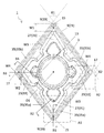
- the upper surface 3 has a polygonal shape, and in the present embodiment, has a rhombus shape.
- the polygonal shape does not mean strictly a polygonal shape.
- the corners on the upper surface 3 in the present embodiment are not strict corners, but are rounded when viewed from above.
- the side located so as to connect adjacent corners may not be strictly linear. For example, it may have a shape that slightly protrudes outward as viewed from above.
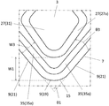
- the upper surface 3 in the present embodiment includes a first corner portion 15 that is an acute angle and a second corner portion 17 that is an obtuse angle as viewed from above. As shown in FIG. 2, there are two first corner portions 15 and two second corner portions 17 on the upper surface 3. Thus, each of the first corner 15 and the second corner 17 may be one or plural.
- the first corner 15 is an acute angle when viewed from above, the angle ⁇ 1 at which two sides extending from the first corner 15 intersect with the first corner 15 is an acute angle. It means that.
- the second corner portion 17 being an obtuse angle means that the angle ⁇ 2 at which two sides extending from the second corner portion 17 intersect with the second corner portion 17 when viewed from above is an obtuse angle. It means that.
- the lower surface 5 is a surface located on the side opposite to the upper surface 3 and functions as a seating surface for the insert pocket when the insert 1 is attached to the holder.
- the lower surface 5 in the present embodiment has substantially the same shape as the upper surface 3, and has a rhombus shape like the upper surface 3.
- the outer periphery of the lower surface 5 overlaps with the outer periphery of the upper surface 3 when seen through on a plane.
- the shapes of the upper surface 3 and the lower surface 5 are not limited to the above forms.
- the shape of the upper surface 3 when viewed from the upper surface is a substantially square shape.
- the shape of the upper surface 3 when viewed from the upper surface is a polygonal shape such as a triangle or a pentagon, Good.
- the upper surface 3 in this embodiment is a rhombus, as a square shape, it is not restricted to such a shape, For example, a parallelogram may be sufficient.
- the insert 1 of the present embodiment has a through hole 13 provided from the center of the upper surface 3 toward the center of the lower surface 5.
- the through hole 13 is provided for inserting a screw when the insert 1 is fixed to the holder of the cutting tool with a screw.
- the central axis O1 of the through hole 13 coincides with an imaginary straight line passing through the center of the upper surface 3 and the center of the lower surface 5.
- the side surface 7 is located between the upper surface 3 and the lower surface 5 and is connected to the upper surface 3 and the lower surface 5.
- the side surface 7 is formed to have a linear shape in a cross section parallel to the central axis O ⁇ b> 1 of the through hole 13.
- the maximum width when the top surface 3 of the insert 1 of this embodiment is viewed from above is 6 to 25 mm.
- the height from the lower surface 5 to the upper surface 3 is 1 to 10 mm.
- the height from the lower surface 5 to the upper surface 3 means a width in a direction parallel to the central axis O ⁇ b> 1 between the upper end of the upper surface 3 and the lower end of the lower surface 5.
- the upper cutting edge 9 is provided on a ridge line where the upper surface 3 and the side surface 7 intersect.
- the lower cutting edge 11 is provided on a ridge line where the lower surface 5 and the side surface 7 intersect.
- the upper cutting edge 9 and the lower cutting edge 11 are used for cutting a work material in cutting. However, the upper cutting edge 9 and the lower cutting edge 11 are not used at the same time, and one of them is used in one cutting process.
- the upper cutting edge 9 is used for cutting.
- the upper surface 3 functions as a seating surface by inverting the insert 1
- the lower cutting edge 11 is used for cutting.
- honing processing may be performed. That is, the ridgeline where the upper surface 3 and the side surface 7 intersect with each other does not have to be a strict line shape due to the intersection between the two surfaces. If the ridgeline is linear, the strength of the upper cutting edge 9 is reduced. Therefore, R honing is applied to the region where the upper surface 3 and the side surface 7 intersect each other so that the region has a curved surface shape.
- the upper cutting edge 9 has a first corner cutting edge 19, a first main cutting edge 21, a second corner cutting edge 23, and a second main cutting edge 25.
- the first corner cutting edge 19 is located on the ridge line in the first corner portion 15.
- the first main cutting edge 21 is adjacent to the first corner cutting edge 19. Specifically, it has a pair of first main cutting edges 21 adjacent to the first corner cutting edge 19.
- the second corner cutting edge 23 is located on the ridge line in the second corner portion 17.
- the second main cutting edge 25 is adjacent to the second corner cutting edge 23. Specifically, it has a pair of second main cutting edges 25 adjacent to the second corner cutting edges 23.
- first main cutting edge 21 and the second main cutting edge 25 are located on the side of the upper surface 3 located between the first corner 15 and the second corner 17, and the first From the first corner 15 toward the second corner 17, the first corner cutting edge 19, the first main cutting edge 21, the second main cutting edge 25, and the second corner cutting edge 23 in this order. Are lined up.
- the first corner cutting edge 19 and the second corner cutting edge 23 are located at corners on the upper surface 3. Since the corner portion has a rounded shape when viewed from above, the first corner cutting edge 19 and the second corner cutting edge 23 each have an outwardly convex arc shape when viewed from above. ing.
- the first main cutting edge 21 and the second main cutting edge 25 are located on the side of the upper surface 3. Therefore, the first main cutting edge 21 and the second main cutting edge 25 in the present embodiment are each linear when viewed from above.
- the insert 1 of this embodiment includes a lower cutting edge 11 having the same configuration as the upper cutting edge 9.
- the cutting edge only the upper cutting edge 9 may be provided, but the economical efficiency can be improved by further providing the lower cutting edge 11 as in the present embodiment. Since the lower cutting edge 11 has the same configuration as the upper cutting edge 9, the lower cutting edge 11 includes the first corner cutting edge 19, the first main cutting edge 21, and the second corner in the upper cutting edge 9. It has a part of the cutting edge corresponding to the cutting edge 23 and the second main cutting edge 25.
- the upper surface 3 in this embodiment has a first breaker protrusion 27 and a second breaker protrusion 29.
- the first breaker protrusion 27 and the second breaker protrusion 29 are located away from the upper cutting edge 9.
- Each of the first breaker protrusion 27 and the second breaker protrusion 29 has a role of curling the proceeding chips.
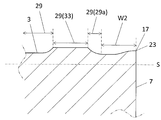
- the first breaker protrusion 27 and the second breaker protrusion 29 have inclined surfaces 27 a and 29 a that are inclined upward as they are separated from the upper cutting edge 9.
- the lower ends of these inclined surfaces 27 a and 29 a constitute the outer edges of the first breaker protrusion 27 and the second breaker protrusion 29.
- an angle formed by the virtual plane S orthogonal to the central axis O1 in the cross section orthogonal to the upper cutting edge 9 and the inclined surface 27a is defined as an inclination angle ⁇ 5 of the inclined surface 27a.
- an angle formed by the virtual plane S orthogonal to the central axis O1 and the inclined surface 29a in the cross section orthogonal to the upper cutting edge 9 is defined as an inclination angle ⁇ 6 of the inclined surface 29a.
- first breaker protrusion 27 and the second breaker protrusion 29 each have a flat surface.
- first breaker protrusion 27 has a flat first surface 31 at its upper end.
- second breaker projection 29 has a flat second surface 33 at the upper end thereof.
- the first surface 31 and the second surface 33 function as surfaces that contact the holder when the upper surface 3 is used as a seating surface for the holder. Therefore, the first surface 31 and the second surface 33 are provided so as to be located on the same plane.
- the first surface 31 and the second surface 33 are parallel to the virtual plane S orthogonal to the height direction, and the height from the virtual plane S is constant. It is.
- said height direction is a direction which passes the center of the upper surface 3, and the center of the lower surface 5, and in the insert 1 of this embodiment, it corresponds with the direction where the central axis O1 of the through-hole 13 is extended.
- the lower surface 5 of the insert 1 of the present embodiment has protrusions having the same configuration as the first breaker protrusion 27 and the second breaker protrusion 29 on the upper surface 3.
- the thickness of the chips becomes relatively thick.
- angular part 17 is an obtuse angle and it cuts using the 2nd corner cutting edge 23, the thickness of a chip becomes comparatively thin.
- the distance W1 between the first breaker protrusion 27 and the first corner cutting edge 19 in the top view is the distance between the second breaker protrusion 29 and the second corner cutting edge 23. Greater than W2.
- the lower surface 5 has the same configuration as the upper surface 3 as in the present embodiment, and when the second corner cutting edge 23 on the upper surface 3 is used for cutting, the second corner cutting edge 23 is used.
- the insert 1 can be seated on the holder at a position close to the bottom of the holder. Therefore, the insert 1 can be stably fixed to the holder.
- the thickness of the chips becomes thick and the chips are difficult to deform, so it is necessary to secure a wide space for curling the chips.
- a relatively large interval W1 between the first breaker protrusion 27 and the first corner cutting edge 19 is ensured. Therefore, the possibility that the chips are clogged in the vicinity of the first corner cutting edge 19 can be reduced.
- the distance W3 between the first breaker projection 27 and the first main cutting edge 21 increases as the distance from the first corner cutting edge 19 increases in a top view. Thereby, the possibility that chips are clogged in the vicinity of the first corner cutting edge 19 can be further reduced.
- the distance W3 between the first breaker protrusion 27 and the first main cutting edge 21 is the above-described configuration, so that the chips are separated from the bisector of the first corner cutting edge 19. It becomes easy to go. Therefore, the possibility that the chips are clogged in the vicinity of the first corner cutting edge 19 can be reduced.
- the interval W4 between the second breaker projection 29 and the second main cutting edge 25 becomes smaller as the distance from the second corner cutting edge 23 increases. Thereby, possibility that chips will be clogged can be further reduced. Specifically, when cutting is performed using the second corner cutting edge 23, the chip flow tends to become unstable because the thickness of the chip is thin.
- the interval W4 between the second breaker projection 29 and the second main cutting edge 25 is the above-described configuration, the chips easily move in the direction approaching the bisector of the second corner cutting edge 23. . Therefore, it becomes easy to sever the chips with an appropriate length. As a result, the possibility of chip clogging can be reduced.
- cutting is performed satisfactorily even when cutting is performed using either the first corner 15 that is an acute angle or the second corner 17 that is an obtuse angle. It can be performed.
- the distance between the breaker protrusion and the cutting edge means the distance between the outer edge of the breaker protrusion and the cutting edge when the insert 1 is viewed from above.
- the distance between the lower end of the breaker protrusion and the cutting edge in the top view is the distance between the breaker protrusion and the cutting edge. It corresponds to the interval.
- the first main cutting edge 21 has a linear shape. Further, the lower end of the first breaker protrusion 27 has a linear portion in a region facing the first main cutting edge 21. Therefore, in a top view of this portion, the interval W3 between the first breaker protrusion 27 and the first main cutting edge 21 increases at a constant ratio as the distance from the first corner cutting edge 19 increases.
- the second main cutting edge 25 has a linear shape. Further, the lower end of the second breaker projection 29 has a linear portion in a region facing the second main cutting edge 25. Therefore, in a top view of this portion, the interval W4 between the second breaker protrusion 29 and the second main cutting edge 25 decreases at a constant ratio as the distance from the second corner cutting edge 23 increases.
- the angle ⁇ 3 formed by the outer edge of the first breaker protrusion 27 and the first main cutting edge 21 is such that the outer edge of the second breaker protrusion 29 and the second main cutting edge 25 are the same. Is larger than the angle ⁇ 4 formed by the two. That is, the angle ⁇ 3 is larger than the angle ⁇ 4.
- the lower surface 5 has the same configuration as the upper surface 3, and the interval W1 is larger than the interval W2.
- the second breaker protrusion 29 can be made closer to the second corner cutting edge 23 by relatively reducing the angle ⁇ 4. Therefore, the interval W2 tends to be smaller.
- the first breaker protrusion 27 can be easily brought close to the first corner cutting edge 19. Therefore, a state in which the first breaker protrusion 27 must be positioned too far from the first corner cutting edge 19 is avoided.
- the minimum value of the interval W1 between the first breaker protrusion 27 and the first main cutting edge 21 is the second breaker protrusion 29 and the second main cutting. It is larger than the minimum value of the interval W2 with the blade 25.
- the first corner cutting edge 19 it is necessary to secure a wide space for curling the chips. Since the first breaker protrusion 27 and the second breaker protrusion 29 are positioned as described above, a wider space for curling chips can be secured.
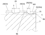
- the upper surface 3 in the present embodiment has a rake surface 35 provided along the upper cutting edge 9.
- the rake face 35 plays a role of scooping off the chips cut by the upper cutting edge 9. Therefore, the chips of the work material flow on the surface of the rake face 35.
- the rake face 35 is inclined so that the height from the lower face 5 becomes constant or lower as the distance from the upper cutting edge 9 increases.
- the rake face 35 is an inclined surface that is inclined so as to approach the lower surface 5 as it approaches the through hole 13.
- the rake angle which is an angle indicating the inclination is indicated by the maximum value of the angle formed by the imaginary plane S perpendicular to the central axis O1 and the rake face 35 in the cross section perpendicular to the upper cutting edge 9.
- the rake face 35 is formed to have a linear shape in a cross section parallel to the central axis O1.
- the insert 1 of the present embodiment has a first rake face 35a and a second rake face 35b as the rake face 35.
- the first rake face 35 a is located between the first breaker protrusion 27 and the first main cutting edge 21.
- the second rake face 35 b is located between the second breaker protrusion 29 and the second main cutting edge 25.
- the rake angle ⁇ 7 of the first rake face 35a and the rake angle ⁇ 8 of the second rake face 35b are the same.
- the upper surface 3 in the present embodiment is a surface including the first breaker protrusion 27, the second breaker protrusion 29, the rake face 35, and the like as described above.
- the insert 1 of this embodiment has an upper surface 3, a lower surface 5, a side surface 7, an upper cutting blade 9, a lower cutting blade 11, and a through hole 13, as in the insert of the first embodiment. ing.
- Examples of the material of the insert 1 include cemented carbide or cermet.
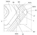
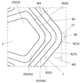
- the upper surface 3 in this embodiment has the 1st breaker protrusion 27, the 2nd breaker protrusion 29, and the rake face 35 similarly to the insert of 1st Embodiment. Furthermore, the insert 1 of the present embodiment further includes a third breaker protrusion 37 in addition to the first breaker protrusion 27 and the second breaker protrusion 29. The third breaker protrusion 37 is located between the first breaker protrusion 27 and the second breaker protrusion 29 in a top view and protrudes toward the side of the upper surface 3.
- the third breaker protrusion 37 By having such a third breaker protrusion 37, when one of the first corner cutting edge 19 and the second corner cutting edge 21 is used for cutting, the other cutting edge may be damaged. Can be suppressed. For example, even when chips are cut using the first corner cutting edge 19, even if the chips extend toward the second corner portion 17, the third breaker protrusion 37 serves as a barrier against the chips. Therefore, the possibility that the second corner cutting edge 23 is damaged is reduced. Similarly, even when chips are cut using the second corner cutting edge 23, even if the chips extend toward the first corner 15, the third breaker protrusion 37 serves as a barrier against the chips. .
- the minimum value of the distance W5 between the third breaker protrusion 37 and the side of the upper surface is the minimum value of the distance W3 between the first breaker protrusion 27 and the first main cutting edge 21, and
- the distance W4 between the second breaker projection 29 and the second main cutting edge 25 is smaller than the minimum value.
- the third breaker protrusion 37 protrudes to the rake face 35 as in the present embodiment in order to prevent the progress of chips in the third breaker protrusion 37 even more stably.
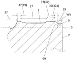
- the third breaker protrusion 37 has an inclined surface 37a that is inclined upward as it is away from the upper cutting edge 9, similarly to the first breaker protrusion 27 and the second breaker protrusion 29.
- the inclination angle ⁇ 9 of the inclined surface 37a of the third breaker protrusion 37 in other words, the maximum value of the rising angle ⁇ 9 is the inclination angle ⁇ 5 of the inclined surface of the first breaker protrusion 27, in other words, the rising angle ⁇ 5.
- the inclination angle ⁇ 9 of the inclined surface 37a is indicated by the angle formed by the inclined plane 37a and the virtual plane S orthogonal to the central axis O1 in the cross section orthogonal to the upper cutting edge 9.
- the third breaker protrusion 37 is provided with a flat third surface 39 at the upper end thereof, similarly to the first breaker protrusion 27 and the second breaker protrusion 29.
- the third surface 39 functions as a surface that contacts the holder when the upper surface 3 is used as a seating surface for the holder. Therefore, the third surface 39 is provided on the same plane as the first surface 31 and the second surface 33.
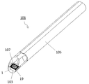
- the cutting tool 101 of the present embodiment is mounted in the insert pocket 103 so that the holder 105 having the insert pocket 103 on the tip side and the upper cutting edge or the lower cutting edge protrude from the tip of the holder 105.
- the above-mentioned cutting insert 1 is provided.
- the insert 1 is mounted so that the first corner cutting edge 19 protrudes from the tip of the holder 105.
- the holder 105 has an elongated bar shape.
- One insert pocket 103 is provided on the tip side of the holder 105.
- the insert pocket 103 is a portion in which the insert is mounted, and is open to the front end surface of the holder 105. At this time, since the insert pocket 103 is also open to the side surface of the holder 105, the insert 1 can be easily mounted.
- the insert pocket 103 has a seating surface parallel to the lower surface of the holder 105 and a constraining side surface inclined with respect to the seating surface.
- Insert 1 is installed in the insert pocket 103.
- the insert 1 is mounted such that the upper cutting edge or the lower cutting edge protrudes toward the distal end side of the holder 105.
- the insert 1 is attached to the holder 105 with a fixing screw 107. That is, the fixing screw 107 is inserted into the through hole of the insert 1, the tip of the fixing screw 107 is inserted into the screw hole formed in the insert pocket 103, and the screw portions are screwed together, whereby the insert 1 is held in the holder 105. It is attached to.
- steel, cast iron or the like can be used.
- steel having high toughness among these members it is preferable to use steel having high toughness among these members.
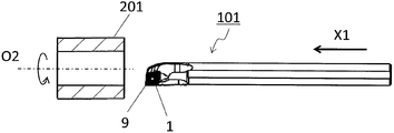
- the cut workpiece is produced by cutting the work material 201.
- the manufacturing method of the cut workpiece in the present embodiment includes the following steps. That is, (1) rotating the work material 201; (2) a step of bringing the upper cutting edge or the lower cutting edge of the cutting tool 101 represented by the above embodiment into contact with the rotating work material 201; (3) a step of separating the cutting tool 101 from the work material 201; It has.
- the work material 201 is rotated around the axis O2, and the cutting tool 101 is relatively brought closer to the work material 201.
- the upper cutting edge 9 in the cutting tool 101 is brought into contact with the work material 201 to cut the work material 201.
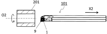
- the cutting tool 101 is relatively moved away from the work material 201.
- the cutting tool 101 is moved in the X1 direction while the axis O2 is fixed and the work material 201 is rotated, thereby being brought closer to the work material 201.
- the work material 201 is cut by bringing the upper work blade 9 in the cutting insert into contact with the rotating work material 201.
- the cutting tool 101 is moved away in the X2 direction while the work material 201 is rotated.
- the cutting tool 101 is brought into contact with the work material 201 by moving the cutting tool 101 in each step, or the cutting tool 101 is separated from the work material 201.
- the cutting tool 101 is not limited to such a form.
- the work material 201 may be brought close to the cutting tool 101 in the step (1). Similarly, in the step (3), the work material 201 may be moved away from the cutting tool 101. In the case of continuing the cutting process, the state in which the workpiece 201 is rotated and the upper cutting edge 9 in the cutting insert 1 is brought into contact with a different portion of the workpiece 201 may be repeated.
- representative examples of the material of the work material 201 include carbon steel, alloy steel, stainless steel, cast iron, or non-ferrous metal.
Landscapes
- Engineering & Computer Science (AREA)
- Mechanical Engineering (AREA)
- Cutting Tools, Boring Holders, And Turrets (AREA)
- Milling Processes (AREA)
Abstract
Description
以下、複数の実施形態の切削インサートについて、図面を用いて詳細に説明する。但し、以下で参照する各図は、説明の便宜上、各実施形態の構成部材のうち、本発明を説明するために必要な主要部材のみを簡略化して示したものである。したがって、本発明の切削インサートは、本明細書が参照する各図に示されていない任意の構成部材を備え得る。また、各図中の部材の寸法は、実際の構成部材の寸法及び各部材の寸法比率等を忠実に表したものではない。
次に、一実施形態の切削工具101について図面を用いて説明する。
次に、本発明の一実施形態の切削加工物の製造方法について図面を用いて説明する。
(1)被削材201を回転させる工程と、
(2)上記実施形態に代表される切削工具101における上切刃又は下切刃を回転している被削材201に接触させる工程と、
(3)切削工具101を被削材201から離す工程と、
を備えている。
3・・・上面
5・・・下面
7・・・側面
9・・・上切刃
11・・・下切刃
13・・・貫通孔
15・・・第1の角部
17・・・第2の角部
19・・・第1のコーナ切刃
21・・・第1の主切刃
23・・・第2のコーナ切刃
25・・・第2の主切刃
27・・・第1のブレーカ突起
27a・・・傾斜面
29・・・第2のブレーカ突起
29a・・・傾斜面
31・・・第1の面
33・・・第2の面
35・・・すくい面
35a・・・第1のすくい面
35b・・・第2のすくい面
37・・・第3のブレーカ突起
39・・・第3の面
101・・・切削工具
103・・・インサートポケット
105・・・ホルダ
107・・・固定ネジ
201・・・被削材
Claims (10)
- 上面視において鋭角である第1の角部及び鈍角である第2の角部を有する多角形状の上面と、下面と、前記上面及び前記下面の間に位置する側面と、前記上面及び前記側面が交差する稜線に設けられた上切刃とを備え、
前記上切刃は、前記第1の角部に位置する第1のコーナ切刃と、該第1のコーナ切刃に隣接する第1の主切刃と、前記第2の角部に位置する第2のコーナ切刃と、該第2のコーナ切刃に隣接する第2の主切刃とを有し、
前記上面は、前記第1の角部に向かって突出する第1のブレーカ突起と、前記第2の角部に向かって突出する第2のブレーカ突起とを有し、
上面視において、前記第1のブレーカ突起と前記第1のコーナ切刃との間隔は、前記第2のブレーカ突起と前記第2のコーナ切刃との間隔よりも大きく、
上面視において、前記第1のブレーカ突起と前記第1の主切刃との間隔は、前記第1のコーナ切刃から離れるにしたがって大きくなり、かつ、前記第2のブレーカ突起と前記第2の主切刃との間隔は、前記第2のコーナ切刃から離れるにしたがって小さくなることを特徴とする切削インサート。 - 上面視において、前記第1のブレーカ突起と前記第1の主切刃との間隔は、前記第1のコーナ切刃から離れるにしたがって一定の比率で大きくなり、かつ、前記第2のブレーカ突起と前記第2の主切刃との間隔は、前記第2のコーナ切刃から離れるにしたがって一定の比率で小さくなっていることを特徴とする請求項1に記載の切削インサート。
- 上面視において、前記第1のブレーカ突起の外縁と前記第1の主切刃とがなす角の角度が、前記第2のブレーカ突起の外縁と前記第2の主切刃とがなす角の角度よりも大きいことを特徴とする請求項2に記載の切削インサート。
- 上面視において、前記第1のブレーカ突起と前記第1の主切刃との間隔の最小値が、前記第2のブレーカ突起と前記第2の主切刃との間隔の最小値よりも大きいことを特徴とする請求項1~3のいずれか1つに記載の切削インサート。
- 前記上面は、前記第1のブレーカ突起と前記第1の主切刃との間に位置する第1のすくい面と、前記第2のブレーカ突起と前記第2の主切刃との間に位置する第2のすくい面とを有し、
前記第1のすくい面のすくい角と前記第2のすくい面のすくい角とが同じであることを特徴とする請求項1~4のいずれか1つに記載の切削インサート。 - 前記上面は、前記第1のブレーカ突起と前記第2のブレーカ突起との間に位置して、前記上面の辺に向かって突出する第3のブレーカ突起を有していることを特徴とする請求項1~5のいずれか1つに記載の切削インサート。
- 上面視において、前記第3のブレーカ突起と前記上面の辺との間隔の最小値が、前記第1のブレーカ突起と前記第1の主切刃との間隔の最小値、及び、前記第2のブレーカ突起と前記第2の主切刃との間隔の最小値よりも小さいことを特徴とする請求項6に記載の切削インサート。
- 前記第3のブレーカ突起の立ち上がり角の最大値が、前記第1のブレーカ突起の立ち上がり角の最大値、及び、前記第2のブレーカ突起の立ち上がり角の最大値よりも大きいことを特徴とする請求項6又は7に記載の切削インサート。
- 先端側にインサートポケットを有するホルダと、
前記上切刃が前記ホルダの先端から突出するように前記インサートポケットに装着された、請求項1~8のいずれか1つに記載の切削インサートとを具備した切削工具。 - 被削材を回転させる工程と、
回転している前記被削材に請求項9に記載の切削工具の前記上切刃を接触させる工程と、
前記切削工具を前記被削材から離す工程とを備えた切削加工物の製造方法。
Priority Applications (4)
| Application Number | Priority Date | Filing Date | Title |
|---|---|---|---|
| JP2016510507A JP6190039B2 (ja) | 2014-03-27 | 2015-03-26 | 切削インサート、切削工具及び切削加工物の製造方法 |
| US15/129,093 US10166606B2 (en) | 2014-03-27 | 2015-03-26 | Cutting insert, cutting tool, and method for manufacturing machined product |
| CN201580015387.0A CN106132605B (zh) | 2014-03-27 | 2015-03-26 | 切削镶刀、切削工具以及切削加工物的制造方法 |
| EP15768168.5A EP3124148B1 (en) | 2014-03-27 | 2015-03-26 | Cutting insert, cutting tool, and method for manufacturing a machined product |
Applications Claiming Priority (2)
| Application Number | Priority Date | Filing Date | Title |
|---|---|---|---|
| JP2014-065293 | 2014-03-27 | ||
| JP2014065293 | 2014-03-27 |
Publications (1)
| Publication Number | Publication Date |
|---|---|
| WO2015147214A1 true WO2015147214A1 (ja) | 2015-10-01 |
Family
ID=54195718
Family Applications (1)
| Application Number | Title | Priority Date | Filing Date |
|---|---|---|---|
| PCT/JP2015/059480 Ceased WO2015147214A1 (ja) | 2014-03-27 | 2015-03-26 | 切削インサート、切削工具及び切削加工物の製造方法 |
Country Status (5)
| Country | Link |
|---|---|
| US (1) | US10166606B2 (ja) |
| EP (1) | EP3124148B1 (ja) |
| JP (1) | JP6190039B2 (ja) |
| CN (1) | CN106132605B (ja) |
| WO (1) | WO2015147214A1 (ja) |
Cited By (2)
| Publication number | Priority date | Publication date | Assignee | Title |
|---|---|---|---|---|
| WO2018025723A1 (ja) * | 2016-08-03 | 2018-02-08 | 京セラ株式会社 | 切削インサート、切削工具及び切削加工物の製造方法 |
| JPWO2018139584A1 (ja) * | 2017-01-30 | 2019-11-07 | 京セラ株式会社 | 切削インサート、ドリル及びそれを用いた切削加工物の製造方法 |
Families Citing this family (8)
| Publication number | Priority date | Publication date | Assignee | Title |
|---|---|---|---|---|
| JP6708183B2 (ja) * | 2017-08-10 | 2020-06-10 | 株式会社タンガロイ | 切削インサート及び切削工具 |
| KR102386942B1 (ko) | 2017-08-23 | 2022-04-14 | 대구텍 유한책임회사 | 드릴용 절삭 인서트 |
| JP7168655B2 (ja) * | 2018-03-27 | 2022-11-09 | 京セラ株式会社 | 切削インサート、切削工具及び切削加工物の製造方法 |
| WO2019227319A1 (zh) * | 2018-05-29 | 2019-12-05 | 南通纺织丝绸产业技术研究院 | 一种含氟聚己内酯膜及其制备方法 |
| DE112019003627T5 (de) * | 2018-07-18 | 2021-04-01 | Kyocera Corporation | Schneideinsatz, schneidwerkzeug und verfahren zur herstellung eines maschinell bearbeiteten produkts |
| CN109014258A (zh) * | 2018-09-10 | 2018-12-18 | 株洲华锐精密工具股份有限公司 | 一种用于钛合金半精加工的可转位车刀片 |
| CN113316494B (zh) * | 2019-10-16 | 2023-07-25 | 住友电工硬质合金株式会社 | 切削刀具 |
| CN114650892B (zh) * | 2019-11-13 | 2024-06-21 | 京瓷株式会社 | 切削刀片、切削工具以及切削加工物的制造方法 |
Citations (3)
| Publication number | Priority date | Publication date | Assignee | Title |
|---|---|---|---|---|
| JPH05177416A (ja) * | 1992-01-07 | 1993-07-20 | Gte Valenite Corp | チップ制御型切断刃インサート |
| JP2006187864A (ja) * | 2001-11-20 | 2006-07-20 | Mitsubishi Materials Corp | スローアウェイチップ |
| DE102008019955A1 (de) * | 2008-04-21 | 2009-10-22 | Kennametal Inc. | Werkzeughalter |
Family Cites Families (17)
| Publication number | Priority date | Publication date | Assignee | Title |
|---|---|---|---|---|
| US5141367A (en) * | 1990-12-18 | 1992-08-25 | Kennametal, Inc. | Ceramic cutting tool with chip control |
| SE509362C2 (sv) * | 1994-03-18 | 1999-01-18 | Sandvik Ab | Diamantbelagd kropp |
| DE19901456B4 (de) * | 1998-01-19 | 2009-07-09 | Mitsubishi Materials Corp. | Wendeschneidplatte |
| JP3812473B2 (ja) * | 2001-11-20 | 2006-08-23 | 三菱マテリアル株式会社 | スローアウェイチップ |
| AT8433U1 (de) * | 2005-03-11 | 2006-08-15 | Ceratizit Austria Gmbh | Wendeschneidplatte |
| JP5028757B2 (ja) | 2005-06-28 | 2012-09-19 | 株式会社タンガロイ | スローアウェイチップ |
| JP4967721B2 (ja) * | 2007-03-07 | 2012-07-04 | 三菱マテリアル株式会社 | 切削インサート |
| DE112008002261B4 (de) * | 2007-08-31 | 2015-06-25 | Kyocera Corporation | Schneideinsatz, Schneidwerkzeug und Schneidverfahren |
| JP2010042462A (ja) | 2008-08-11 | 2010-02-25 | Sumitomo Electric Hardmetal Corp | 旋削用チップ |
| AT11676U1 (de) * | 2009-10-02 | 2011-03-15 | Ceratizit Austria Gmbh | Schneideinsatz für ein schneidwerkzeug |
| KR101067156B1 (ko) * | 2009-12-07 | 2011-09-22 | 대구텍 유한회사 | 다기능 절삭 공구 및 그를 위한 공구 홀더 |
| CN201579436U (zh) * | 2009-12-28 | 2010-09-15 | 中硬金属切削(大连)有限公司 | 一种半精加工的双面槽型可转位数控车削刀片 |
| CN102844139B (zh) * | 2010-06-30 | 2013-10-16 | 京瓷株式会社 | 镶刀及切削工具、以及使用该切削工具的切削加工物的制造方法 |
| SE535166C2 (sv) * | 2010-08-25 | 2012-05-08 | Sandvik Intellectual Property | Dubbelsidigt, indexerbart svarvskär med spetsig spånvinkel |
| US8967920B2 (en) * | 2011-09-13 | 2015-03-03 | Iscar, Ltd. | Cutting insert and chip-control arrangement therefor |
| SE536295C2 (sv) * | 2011-09-23 | 2013-08-06 | Sandvik Intellectual Property | Månghörnigt svarvskär med förbättrad spånkontroll |
| DE102014102800A1 (de) * | 2013-03-04 | 2014-09-04 | Kennametal India Limited | Schneideinsatz mit assymetrischem Spanformer |
-
2015
- 2015-03-26 CN CN201580015387.0A patent/CN106132605B/zh active Active
- 2015-03-26 JP JP2016510507A patent/JP6190039B2/ja active Active
- 2015-03-26 EP EP15768168.5A patent/EP3124148B1/en active Active
- 2015-03-26 WO PCT/JP2015/059480 patent/WO2015147214A1/ja not_active Ceased
- 2015-03-26 US US15/129,093 patent/US10166606B2/en active Active
Patent Citations (3)
| Publication number | Priority date | Publication date | Assignee | Title |
|---|---|---|---|---|
| JPH05177416A (ja) * | 1992-01-07 | 1993-07-20 | Gte Valenite Corp | チップ制御型切断刃インサート |
| JP2006187864A (ja) * | 2001-11-20 | 2006-07-20 | Mitsubishi Materials Corp | スローアウェイチップ |
| DE102008019955A1 (de) * | 2008-04-21 | 2009-10-22 | Kennametal Inc. | Werkzeughalter |
Cited By (6)
| Publication number | Priority date | Publication date | Assignee | Title |
|---|---|---|---|---|
| WO2018025723A1 (ja) * | 2016-08-03 | 2018-02-08 | 京セラ株式会社 | 切削インサート、切削工具及び切削加工物の製造方法 |
| CN109562459A (zh) * | 2016-08-03 | 2019-04-02 | 京瓷株式会社 | 切削刀片、切削工具及切削加工物的制造方法 |
| JPWO2018025723A1 (ja) * | 2016-08-03 | 2019-04-25 | 京セラ株式会社 | 切削インサート、切削工具及び切削加工物の製造方法 |
| US10710170B2 (en) | 2016-08-03 | 2020-07-14 | Kyocera Corporation | Cutting insert, cutting tool, and method of manufacturing machined product |
| DE112017003869B4 (de) | 2016-08-03 | 2024-05-29 | Kyocera Corporation | Schneideinsatz, Schneidwerkzeug und Verfahren des Herstellens eines maschinell-bearbeiteten Produkts |
| JPWO2018139584A1 (ja) * | 2017-01-30 | 2019-11-07 | 京セラ株式会社 | 切削インサート、ドリル及びそれを用いた切削加工物の製造方法 |
Also Published As
| Publication number | Publication date |
|---|---|
| US10166606B2 (en) | 2019-01-01 |
| JPWO2015147214A1 (ja) | 2017-04-13 |
| US20170120342A1 (en) | 2017-05-04 |
| CN106132605B (zh) | 2018-04-06 |
| JP6190039B2 (ja) | 2017-08-30 |
| EP3124148B1 (en) | 2019-02-27 |
| EP3124148A1 (en) | 2017-02-01 |
| CN106132605A (zh) | 2016-11-16 |
| EP3124148A4 (en) | 2017-11-22 |
Similar Documents
| Publication | Publication Date | Title |
|---|---|---|
| JP6190039B2 (ja) | 切削インサート、切削工具及び切削加工物の製造方法 | |
| JP6356781B2 (ja) | 切削インサート、切削工具及び切削加工物の製造方法 | |
| JP6645964B2 (ja) | 切削インサート、切削工具及び切削加工物の製造方法 | |
| JP6343016B2 (ja) | 切削インサート、切削工具及び切削加工物の製造方法 | |
| JP5844881B2 (ja) | 切削インサート、切削工具および切削加工物の製造方法 | |
| JP5606636B2 (ja) | 切削インサート、切削工具および切削加工物の製造方法 | |
| JP6861269B2 (ja) | 切削インサート、切削工具及び切削加工物の製造方法 | |
| JP5815868B2 (ja) | 切削インサートおよび切削工具、ならびにそれらを用いた切削加工物の製造方法 | |
| CN111902232B (zh) | 切削刀片、切削工具及切削加工物的制造方法 | |
| CN105682835B (zh) | 切削镶刀及切削工具、使用它们的切削加工物的制造方法 | |
| JP6462126B2 (ja) | 切削インサート、切削工具及びこれを用いた切削加工物の製造方法 | |
| WO2013129016A1 (ja) | 切削インサート、切削工具および切削加工物の製造方法 | |
| CN114025902B (zh) | 切削刀片、切削刀具以及切削加工物的制造方法 | |
| JPWO2019004030A1 (ja) | 切削インサート、切削工具及び切削加工物の製造方法 | |
| JP6166148B2 (ja) | 切削インサート、切削工具および切削加工物の製造方法 | |
| JP6352639B2 (ja) | 切削インサート、切削工具および切削加工物の製造方法 | |
| JP6282921B2 (ja) | 切削インサート、切削工具および切削加工物の製造方法 | |
| JP7381599B2 (ja) | 切削インサート、切削工具及び切削加工物の製造方法 | |
| JP6306433B2 (ja) | 切削インサート、切削工具および切削加工物の製造方法 | |
| JP6363355B2 (ja) | 切削インサート、切削工具および被削加工物の製造方法 |
Legal Events
| Date | Code | Title | Description |
|---|---|---|---|
| 121 | Ep: the epo has been informed by wipo that ep was designated in this application |
Ref document number: 15768168 Country of ref document: EP Kind code of ref document: A1 |
|
| ENP | Entry into the national phase |
Ref document number: 2016510507 Country of ref document: JP Kind code of ref document: A |
|
| REEP | Request for entry into the european phase |
Ref document number: 2015768168 Country of ref document: EP |
|
| WWE | Wipo information: entry into national phase |
Ref document number: 2015768168 Country of ref document: EP |
|
| WWE | Wipo information: entry into national phase |
Ref document number: 15129093 Country of ref document: US |
|
| NENP | Non-entry into the national phase |
Ref country code: DE |