INTERFERENCE PARAMETER SIGNALING FOR EFFICIENT
INTERFERENCE CANCELLATION AND SUPPRESSION
The present invention relates to transmission of interference parameters from a serving node to
a receiving device in a cellular communication system.
TECHNOLOGY BACKGROUND
Third generation(3G)mobile cellular systems,such as,for instance,universal mobile
telecommunication systems(UMTS)standardized within the third generation partnership project
(3GPP)have been based on wideband code division multiple access(WCDMA)radio access
technology.Today,3G systems are being deployed on a broad scale all around the world.After
enhancing this technology by introducing high-speed downlink packet access(HSDPA)and an
enhanced uplink,also referred to as high-speed uplink packet access(HSUPA),the next major
step in evolution of the UMTS standard has brought the combination of orthogonal frequency
division multiplexing(OFDM)for the downlink and single carrier frequency division multiplexing
access(SC-FDMA)for the uplink.This system has been named long term evolution(LTE)since
it has been intended to cope with future technology evolutions.
The LTE system represents efficient packet based radio access and radio access networks that
provide full IP-based functionalities with low latency and low cost.The downlink supports data
modulation schemes QPSK,16QAM,and64QAM and the uplink supports QPSK,16QAM,and
at least for some devices also64QAM,for physical data channel transmissions.The term
“downlink”denotes direction from the network to the terminal.The term“uplink”denotes
direction from the terminal to the network.
LTE’s network access is extremely flexible,using a number of defined channel bandwidths
between1.4and20MHz,contrasted with UMTS terrestrial radio access(UTRA)fixed5MHz
channels.Spectral efficiency is increased by up to four-fold compared with UTRA,and
improvements in architecture and signaling reduce round-trip latency.Multiple Input/Multiple
Output(MIMO)antenna technology should enable10times as many users per cell as3GPP’s
original WCDMA radio access technology.To suit as many frequency band allocation
arrangements as possible,both paired(frequency division duplex FDD)and unpaired(time
division duplex TDD)band operation is supported.LTE can co-exist with earlier3GPP radio
technologies,even in adjacent channels,and calls can be handed over to and from all3GPP’s
previous radio access technologies.
An LTE network architecture including network entities and interfaces between them is
exemplified in Figure1.As can be seen in Figure1,the LTE architecture supports
interconnection of different radio access networks(RAN)such as UTRAN or GERAN(GSM
EDGE Radio Access Network),which are connected to the EPC via the Serving GPRS Support
Node(SGSN).In a3GPP mobile network,the mobile terminal110(called User Equipment,UE,
or device)is attached to the access network via the Node B(NB)in the UTRAN and via the
evolved Node B(eNB)in the E-UTRAN access.The NB and eNB120entities are known as
base station in other mobile networks.There are two data packet gateways located in the EPS
for supporting the UE mobility–Serving Gateway(SGW)130and Packet Data Network
Gateway160(PDN-GW or shortly PGW).Assuming the E-UTRAN access,the eNB entity120
may be connected through wired lines to one or more SGWs via the S1-U interface(“U”stays for
“user plane”)and to the Mobility Management Entity140(MME)via the S1-MMME interface.
The SGSN150and MME140are also referred to as serving core network(CN)nodes.
As shown above,the E-UTRAN consists of an eNodeB,providing the E-UTRA user plane
(PDCP/RLC/MAC/PHY)and control plane(RRC)protocol terminations towards the user
equipment(UE).The eNodeB(eNB)hosts the Physical(PHY),Medium Access Control(MAC),
Radio Link Control(RLC)and Packet Data Control Protocol(PDCP)layers that include the
functionality of user-plane header-compression and encryption.It also offers Radio Resource
Control(RRC)functionality corresponding to the control plane.It performs many functions
including radio resource management,admission control,scheduling,enforcement of negotiated
uplink Quality of Service(QoS),cell information broadcast,ciphering/deciphering of user and
control plane data,and compression/decompression of downlink/uplink user plane packet
headers.The eNBs are interconnected with each other by means of the X2interface.
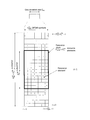
Figure2illustrates structure of a component carrier in LTE Release8and later releases.The
downlink component carrier of the3GPP LTE Release8is sub-divided in the time-frequency
domain in so-called sub-frames each of which is divided into two downlink slots,one of which is
shown in Figure2as corresponding to a time period Tslot.The first downlink slot comprises a
control channel region within the first OFDM symbol(s).Each sub-frame consists of a given
number of OFDM symbols in the time domain,each OFDM symbol spanning over the entire
bandwidth of the component carrier.
In particular,the smallest unit of resources that can be assigned by a scheduler is a resource
block also called physical resource block(PRB).A PRB is defined as
consecutive OFDM
symbols in the time domain and
consecutive sub-carriers in the frequency domain.In
practice,the downlink resources are assigned in resource block pairs.A resource block pair
consists of two resource blocks.It spans
consecutive sub-carriers in the frequency domain
and the entire
modulation symbols of the sub-frame in the time domain.
may be
either6or7resulting in either12or14OFDM symbols in total.Consequently,a physical
resource block consists of
resource elements corresponding to one slot in the time
domain and180kHz in the frequency domain(further details on the downlink resource grid can
be found,for example,in3GPP TS36.211,“Evolved universal terrestrial radio access(E-UTRA);
physical channels and modulations(Release10)”,version10.4.0,2012,Section6.2,freely
available at www.3gpp.org,which is incorporated herein by reference).While it can happen that
some resource elements within a resource block or resource block pair are not used even
though it has been scheduled,for simplicity of the used terminology still the whole resource
block or resource block pair is assigned.Examples for resource elements that are actually not
assigned by a scheduler include reference signals,broadcast signals,synchronization signals,
and resource elements used for various control signal or channel transmissions.
The number of physical resource blocks
in downlink depends on the downlink transmission
bandwidth configured in the cell and is at present defined in LTE as being from the interval of6
to110(P)RBs.It is common practice in LTE to denote the bandwidth either in units of Hz(e.g.
10MHz)or in units of resource blocks,e.g.for the downlink case the cell bandwidth can
equivalently expressed as e.g.10MHz or
Generally,it may be assumed that a resource block designates the smallest resource unit on an
air interface of a mobile communication that can be assigned by a scheduler for transmitting
data.The dimensions of a resource block may be any combination of time(e.g.time slot,sub-
frame,frame,etc.for time division multiplex(TDM)),frequency(e.g.subband,carrier frequency,
etc.for frequency division multiplex(FDM)),code(e.g.spreading code for code division
multiplex(CDM)),antenna(e.g.Multiple Input Multiple Output(MIMO)),etc.depending on the
access scheme used in the mobile communication system.
In3GPP LTE Release8the downlink control signalling is basically carried by the following three
physical channels:
-Physical control format indicator channel(PCFICH)for indicating the number of OFDM
symbols used for control signalling in a sub-frame(i.e.the size of the control channel
region);
-Physical hybrid ARQ indicator channel(PHICH)for carrying the downlink ACK/NACK
associated with uplink data transmission;and
-Physical downlink control channel(PDCCH)for carrying downlink scheduling
assignments and uplink scheduling assignments.
The PCFICH is sent from a known position within the control signalling region of a downlink sub-
frame using a known pre-defined modulation and coding scheme.The user equipment decodes
the PCFICH in order to obtain information about a size of the control signalling region in a sub-
frame,for instance,the number of OFDM symbols.If the user equipment(UE)is unable to
decode the PCFICH or if it obtains an erroneous PCFICH value,it will not be able to correctly
decode the L1/L2control signalling(PDCCH)comprised in the control signalling region,which
may result in losing all resource assignments contained therein.
The PDCCH carries downlink control information,such as,for instance,scheduling grants for
allocating resources for downlink or uplink data transmission.The PDCCH for the user
equipment is transmitted on the first of either one,two or three OFDM symbols according to
PCFICH within a sub-frame.
Physical downlink shared channel(PDSCH)is used to transport user data.PDSCH is mapped
to the remaining OFDM symbols within one sub-frame after PDCCH.The PDSCH resources
allocated for one UE are in the units of resource block for each sub-frame.
Physical uplink shared channel(PUSCH)carries user data.Physical Uplink Control Channel
(PUCCH)carries signalling in the uplink direction such as scheduling requests,HARQ positive
and negative acknowledgements in response to data packets on PDSCH,and channel state
information(CSI).
User data(IP packets)to be transmitted over the communication network may be generated by
the user application.They may include speech,video,text,or any other media possibly
compressed and encapsulated into other protocols before forming the IP packets.The IP
packets are in EUTRAN further processed on the PDCP layer resulting in addition of a PDCP
header.The PDCP packets formed in this manner are further segmented and/or reassembled
(reassembling being shown in the figure)into RLC packets to which an RLC header is added.
One or more RLC packets are then encapsulated into a MAC packet including also a MAC
header and padding,if necessary.The MAC packet is also called“transport block”.Thus,a
transport block is from the point of view of the physical layer a packet of user data entering the
physical layer.There are predefined transport block sizes(TBS)which may be used in LTE.
The transport block is then within one transmission time interval(TTI)mapped onto the
subframes on the physical layer(PHY).Details of the mapping of data starting with transport
blocks up to the interleaving is shown in Figures5.2.2-1and5.3.2-1and described in the related
description of the3GPP TS36.212,v.10.4.0,“Evolved universal terrestrial radio access(E-
UTRA);Multiplexing and channel coding”available freely at
www.3gpp.org and incorporated
herein by reference,for the uplink and downlink transmission of user data respectively.
Furthermore,the physical channel mapping is described in detail in Figure6.3-1and Figure5.3-
1for downlink and uplink,respectively,and the related description in3GPP TS36.211,v10.4.0.
The principle of link adaptation is fundamental to the design of a radio interface which is efficient
for packet-switched data traffic.Unlike the early versions of UMTS(Universal Mobile
Telecommunication System),which used fast closed-loop power control to support circuit-
switched services with a roughly constant data rate,link adaptation in LTE adjusts the
transmitted data rate(modulation scheme and channel coding rate)dynamically to match the
prevailing radio channel capacity for each user.
For the downlink data transmissions in LTE,the eNodeB typically selects the modulation
scheme and code rate(MCS)depending on a prediction of the downlink channel conditions.An
important input to this selection process is the Channel State Information(CSI)feedback
(mentioned above)transmitted by the User Equipment(UE)in the uplink to the eNodeB.
Channel state information is used in a multi-user communication system,such as for example
3GPP LTE to determine the quality of channel resource(s)for one or more users.In general,in
response to the CSI feedback the eNodeB can select between QPSK,16-QAM and64-QAM
schemes and a wide range of code rates.This CSI information may be used to aid in a multi-
user scheduling algorithm to assign channel resources to different users,or to adapt link
parameters such as modulation scheme,coding rate or transmit power,so as to exploit the
assigned channel resources to its fullest potential.
The uplink and downlink resource grants(grants enabling the UE to transmit data in downlink
and uplink,respectively)are transmitted from the eNodeB to the UE in a downlink control
information(DCI)via PDCCH.The downlink control information may be transmitted in different
formats,depending on the signaling information necessary.In general,the DCI may include:
-a resource block assignment(RBA),
-modulation and coding scheme(MCS).
It may include further information,depending on the signaling information necessary,as also
described in Section9.3.2.3of the book“LTE:The UMTS Long Term Evolution from theory to
practice”by S.Sesia,I.Toufik,M.Baker,Apr.2009,John Wiley&Sons,ISBN978-0-470-
69716-0,which is incorporated herein by reference.For instance,the DCI may further include
HARQ related information such as redundancy version(RV),HARQ process number,or new
data indicator(NDI);MIMO related information such as pre-coding;power control related
information,etc.
As described above,in order to inform the scheduled users about their allocation status,
transport format and other data-related information(e.g.HARQ information,transmit power
control(TPC)commands),L1/L2control signaling is transmitted on the downlink along with the
data.L1/L2control signaling is multiplexed with the downlink data in a subframe,assuming that
the user allocation can basically change from subframe to subframe.It should be noted that user
allocation might also be performed on a TTI(Transmission Time Interval)basis,where the TTI
length can be in general a multiple of the subframes or correspond to a subframe.The TTI
length may be fixed in a service area for all users,may be different for different users,or may
even by dynamic for each user.Generally,the L1/2control signaling needs only be transmitted
once per TTI.Without loss of generality,the following assumes that a TTI is equivalent to one
subframe.
The L1/L2control signaling is transmitted on the Physical Downlink Control Channel(PDCCH).
A PDCCH carries a message as a Downlink Control Information(DCI),which in most cases
includes resource assignments(allocations)and other control information for a mobile terminal
or groups of UEs.In general,several PDCCHs can be transmitted in one subframe.It should be
noted that in3GPP LTE,assignments for uplink data transmissions,also referred to as uplink
scheduling grants or uplink resource assignments,are also transmitted on the PDCCH.
Generally,the information sent on the L1/L2control signaling for assigning uplink or downlink
radio resources(particularly LTE(-A)Release10)can be categorized to the following items:
-
User identity,indicating the user that is allocated.This is typically included in the
checksum by masking the CRC with the user identity.Then,the users(UEs)perform
blind decoding by demasking the identities transmitted in the search space(i.e.in the
resources configured as search space in which the respective terminals have to monitor
the control information whether there is data for them).
-
Resource allocation information,indicating the resources(Resource Blocks,RBs)on
which a user is allocated.Note,that the number of RBs on which a user is allocated can
thus be dynamic.In particular,the number of the resource blocks(frequency domain)is
carried by the resource allocation information.The position in the time domain(subframe)
is given by the subframe in which the PDCCH is received and a predefined rule(the
resources are allocated fixed number of subframes after the PDCCH subframe).
-
Carrier indicator,which is used if a control channel transmitted on a first carrier assigns
resources that concern a second carrier,i.e.resources on a second carrier or resources
related to a second carrier if carrier aggregation is applied.
-
Modulation and coding scheme that determines the employed modulation scheme and
coding rate(length of the transport block to be coded).
-
HARQ information,such as a new data indicator(NDI)and/or a redundancy version(RV)
that is particularly useful in retransmissions of data packets or parts thereof.In particular,
new data indicator indicated whether the allocation is for an initial transmission of data or
for a retransmission of data.Redundancy version indicates the coding applied to the
retransmitted data(in LTE incremental redundancy combining is supported,meaning that
each retransmission may include the data of the first transmission differently coded,i.e.
may include parity bits which together with the already received
transmission/retransmission(s)finally enable decoding).
-
Power control commands to adjust the transmit power of the assigned uplink data or
control information transmission.
-
Reference signal information such as the applied cyclic shift and/or orthogonal cover
code index,which are to be employed for transmission or reception of reference signals
related to the assignment.
-
Uplink or downlink assignment index that is used to identify an order of assignments,
which is particularly useful in TDD systems.
-
Hopping information,e.g.an indication whether and how to apply resource hopping in
order to increase the frequency diversity.
-
CSI request,which is used to trigger the transmission of channel state information in an
assigned resource.
-
Multi-cluster information,which is a flag used to indicate and control whether the
transmission occurs in a single cluster(contiguous set of RBs)or in multiple clusters(at
least two non-contiguous sets of contiguous RBs).Multi-cluster allocation has been
introduced by3GPP LTE-(A)Release10.
It is to be noted that the above listing is non-exhaustive,and not all mentioned information items
need to be present in each PDCCH transmission depending on the DCI format that is used.
Downlink control information occurs in several formats that differ in overall size and also in the
information contained in its fields.The different DCI formats that are currently defined for LTE
are as follows and described in detail in3GPP TS36.212,v.12.0.0“Multiplexing and channel
coding”,section5.3.3.1(available at http://www.3gpp.org and incorporated herein by reference).
For instance,DCI Format0is used for the transmission of resource grants for the PUSCH,using
single-antenna port transmissions in uplink transmission mode1or2.
In order for the UE to identify whether it has received a PDCCH transmission correctly,error
detection is provided by means of a16-bit CRC appended to each PDCCH(i.e.DCI).
Furthermore,it is necessary that the UE can identify which PDCCH(s)are intended for it.This
could in theory be achieved by adding an identifier to the PDCCH payload;however,it turns out
to be more efficient to scramble the CRC with the“UE identity”,which saves the additional
overhead.The CRC may be calculated and scrambled as defined in detail by3GPP in TS
36.212,Section5.3.3.2“CRC attachment”,incorporated hereby by reference.The section
describes how error detection is provided on DCI transmissions through a Cyclic Redundancy
Check(CRC).A brief summary is given below.The entire payload is used to calculate the CRC
parity bits.The parity bits are computed and attached.In the case where UE transmit antenna
selection is not configured or applicable,after attachment,the CRC parity bits are scrambled
with the corresponding RNTI.
The scrambling may further depend on the UE transmit antenna selection,as apparent from TS
36.212.In the case where UE transmit antenna selection is configured and applicable,after
attachment,the CRC parity bits are scrambled with an antenna selection mask and the
corresponding RNTI.As in both cases the RNTI is involved in the scrambling operation,for
simplicity and without loss of generality the following description of the embodiments simply
refers to the CRC being scrambled(and descrambled,as applicable)with an RNTI,which
should therefore be understood as notwithstanding e.g.a further element in the scrambling
process such as an antenna selection mask.
Correspondingly,the UE descrambles the CRC by applying the“UE identity”and,if no CRC
error is detected,the UE determines that PDCCH carries its control information intended for
itself.The terminology of“masking”and“de-masking”is used as well,for the above-described
process of scrambling a CRC with an identity.The“UE identity”mentioned above with which the
CRC of the DCI may be scrambled can also be a SI-RNTI(System Information Radio Network
Temporary Identifier),which is not a“UE identity”as such,but rather an identifier associated
with the type of information that is indicated and transmitted,in this case the system information.
The SI-RNTI is usually fixed in the specification and thus known a priori to all UEs.
The physical downlink control channel(PDCCH)carries e.g.scheduling grants for allocating
resources for downlink or uplink data transmission.Multiple PDCCHs can be transmitted in a
subframe.The PDCCH for the user equipments is transmitted on the first
OFDM
symbols(usually either1,2or3OFDM symbols as indicated by the PCFICH,in exceptional
cases either2,3,or4OFDM symbols as indicated by the PCFICH)within a subframe,extending
over the entire system bandwidth;the system bandwidth is typically equivalent to the span of a
cell or component carrier.The region occupied by the first
OFDM symbols in the time
domain and the
subcarriers in the frequency domain is also referred to as PDCCH
region or control channel region.The remaining
OFDM symbols in
the time domain on the
subcarriers in the frequency domain is referred to as the
PDSCH region or shared channel region(see below).
For a downlink grant(i.e.resource assignment)on the physical downlink shared channel
(PDSCH),the PDCCH assigns a PDSCH resource for(user)data within the same subframe.
The PDCCH control channel region within a subframe consists of a set of Control Channel
Elements,CCEs where the total number of CCEs in the control region of subframe is distributed
throughout time and frequency control resource.Multiple CCEs can be combined to effectively
reduce the coding rate of the control channel.CCEs are combined in a predetermined manner
using a tree structure to achieve different coding rate.Control channel elements are separately
allocable units smaller than the entire physical resource block.They enable finer resource
assignment for the control channel in which smaller amounts of data are transported.
On a transport channel level,the information transmitted via the PDCCH is also referred to as
L1/L2control signaling(for details on L1/L2control signaling see above).
For uplink resource assignments(for transmissions on the Physical Uplink Shared CHannel
(PUSCH))signaled on PDCCH in LTE,the L1/L2control information does not contain a HARQ
process number,since a synchronous HARQ protocol is employed for LTE uplink.The HARQ
process to be used for an uplink transmission is given by the timing.Furthermore it should be
noted that the redundancy version(RV)information is jointly encoded with the transport format
information,i.e.the RV info is embedded in the transport format(TF)field.The TF respectively
modulation and coding scheme(MCS)field has for example a size of bits,which corresponds to
32entries.3TF/MCS table entries are reserved for indicating RVs1,2or3.The remaining MCS
table entries are used to signal the MCS level(TBS)implicitly indicating RV0.
For details on the TBS/RV signaling for uplink assignments on PDCCH please see3GPP TS
36.213,“Evolved Universal Terrestrial Radio Access(E-UTRA);Physical layer procedures”,
version3GPP TS36.213,v.10.4.0,2012(available at http://www.3gpp.org and incorporated
herein by reference).The size of the CRC field of the PDCCH is16bits.
For downlink assignments(PDSCH)signaled on PDCCH in LTE the Redundancy Version(RV)
is signaled separately in a two-bit field.Furthermore the modulation order information is jointly
encoded with the transport format information.Similar to the uplink case there is5bit MCS field
signaled on PDCCH.Three of the entries are reserved to signal an explicit modulation order,
providing no Transport format(Transport block)info.For the remaining29entries modulation
order and Transport block size info are signaled.
The idea behind the concept of interference cancellation and interference suppression is that the
effective signal to interference power ratio in the receiver can be increased if the interference
fraction of the received signal can be removed or suppressed in the receiver.In order to achieve
this,the knowledge of the type and strength of the interference is beneficial.
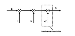
Figure4illustrates the basic concept of interference cancellation in the receiver.A signal S is
generated by the receiver and transmitted over a channel.During the transmission it is
superimposed by interference I and noise N.This results in a disturbed signal which is inputted
to a receiver and which may lead to some bit errors in the demodulator.In order to improve the
reception and in particular,the bit error rate resulting from demodulation and decoding,
interference cancellation(marked by a dashed rectangle in Fig.4)may be applied.In particular,
an interference estimation I’available in the receiver is used to recover signal S’which is further
used as an input for the demodulator reducing therewith the bit error rate.In this example,the
recovery is achieved by subtracting the estimated interference signal I’form the received signal
S+N+I.The performance of interference cancellation strongly depends on the accuracy of the
interference estimation I’.In case of a very inaccurate interference estimation which corresponds
to a large difference between I and I’,it could even result in an increased disturbance of the
demodulator input yielding an increased bit error rate.
The interference I is determined by a combination of some transmission(interference)
parameters.The accuracy of the interference estimation I’increases with the amount of
information regarding the interference parameters that is available on the receiver side.
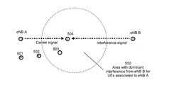
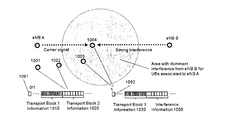
Figure5shows a typical scenario with interference from a single dominant interfering cell.UEs
501,502,503and504are served by an eNB A and experience interference from eNB B.UE
501and UE502experience weak interference from eNB B since they are far away from the
interference source(eNB B),while UE503and UE504experience strong interference from eNB
B.The dashed circle500indicates the area,in which the interference from the eNB B is
dominant for the terminals served by the eNB A.For the purpose of improving the reception
quality in the terminals located within the area500,the interference cancellation and thus also
the accuracy of the interference estimation may be essential.
Recently,3GPP initiated a study item concerning network assisted interference cancellation and
suppression(NAICS)for the downlink in3GPP LTE systems.Details are described in3GPP TR
36.866v12.0.0,March2014,“Study on Network-Assisted Interference Cancellation and
Suppression(NAIC)for LTE”(referred to as“NAICS technical report”in the following).Based
thereon,a subsequent work item is supposed to specify inclusion of the network assisted
interference cancellation into the standard,as can be seen from RP-140519,“New work item
proposal for network assistance interference cancellation and suppression for LTE”,3GPP
RAN#63,March2014,referred to as“NAICS work item”in the following.
The parameters in an LTE system which influence the interference(interference parameters)
comprise
-Position of reference signals(pilot)within the resource grid of the interfering transmission
(e.g.by eNB B of figure5),
-Effective interference channel including precoding on the interference transmitter side,
-Interferer resource allocation in terms of allocated resources(PRBs,CFI,etc.),
-Number of spatial transmission layers of the interfering transmission,
-Modulation order of the interfering transmission,
-Channel coding parameters of the interfering transmission(code rate,redundancy
version,etc.).
The amount of required interference information depends hereby on the receiver type.The
receiver types investigated at3GPP range from receivers that suppress the interference by
means of spatial filtering of the sum signal to receivers that perform the complete decoding of
code words transmitted by the interference source.
A receiver that performs merely an interference suppression by means of spatial filtering of the
received signal(e.g.E-LMMSE-IRC in the NAICS technical report,Section7.2)requires only
information about the effective interference channel(including precoding on the interference
transmitter side)per spatial layer,while information about modulation and coding scheme,
redundancy version,etc.are not required.
On the other hand,a receiver that performs interference cancellation either on symbol(SL-IC,cf.
NAICS technical report,Section7.4)or on codeword level(CW-IC,cf.NAICS technical report,
Section7.4)requires a significantly extended amount of interference information.In particular,
on the receiver side it has to be known which modulation symbol was transmitted in order to
perform effective interference cancellation as show in Figure4.A detailed description of the
receiver types studied at3GPP RAN1within the scope of NAISC is given in the NAICS cf.
NAICS technical report cited above.Accordingly,also different approaches can be considered
for obtaining interference parameters in LTE system:
-Blind detection:The interference parameters are estimated within the receiver by
means of hypothesis testing.This approach does not involve any network assistance but
constitutes increased computation complexity in the receiver.Depending on which
parameters have to be determined,the additional complexity can be significant.The
advantage of such an approach is that no additional signalling is required.
-Overhearing of control signals(DCI,reference signals,etc.)from interfering eNB:
The interference parameters are determined in the receiver by listening to existing
control signals from the interfering cell itself.This does not require any additional network
assistance since the transmission parameters of the interfering signal are anyway
already provided to UEs associated to the interfering eNB.The disadvantage of this
approach is that the UE has to be able to receive signals from both serving and
interfering eNB in parallel.It furthermore requires a significant amount of blind detection
of signals from the interfering cell which increases the implementation complexity of the
receiver.
-L1signalling from interfering eNB:This approach addresses the introduction of new
L1(physical layer)signalling for the provision of interference information.This control
information would be transmitted by the interfering eNB and received by interference
victim UEs that are associated to a neighbouring eNB.The disadvantage of this
approach is that the UE has to be able to receive signals from both serving and
interfering eNB in parallel.
-Higher-layer signalling from serving eNB:Interference information is provided to the
interference victim UE by the serving eNB by means of downlink control messages on
MAC layer or above.The serving eNB has knowledge of the transmission parameters
used in the interfering cell due to backhaul communication.Due to the latency involved in
higher-layer signalling,the approach can only be applied for interference parameters that
do not change frequently.
-L1signalling from serving eNB:Interference information is provided to the interference
victim UE by the serving eNB by means of downlink control signalling on the physical
layer.The serving eNB has knowledge of the transmission parameters used in the
interfering cell due to backhaul communication.In contrast to using higher-layer
signalling,the interference information can be updated more frequently if the backhaul
connection between serving and interfering eNB meets the required delay and capacity
needs.A crucial precondition of this approach is a backhaul connection with sufficient
capacity and latency.The preferred use case would therefore be intra-site coordination
or coordination for remote radio heads(RRH).
Thus,each of the above approaches for obtaining the interference parameters have their
advantages and disadvantages.
SUMMARY OF THE INVENTION
It is the aim of the present invention,to provide an efficient manner of obtaining at the receiver
the interference parameters to be used in interference suppression.
This invention provides a solution for providing information regarding interference parameters to
the receivers by means of explicit signalling of interference parameters or sets of interference
parameter candidates.The interference information is provided by means of L1signalling from
the serving eNB to the controlled device(such as a terminal,DCI receiving device).
This is achieved by the features as set forth in the independent claims.
Preferred embodiments of the present invention are the subject matter of the dependent claims.
The particular approach of the present invention is to provide the interference parameters within
a downlink control information.Based on the interference parameters,the receiving device can
estimate the interference and employ the estimate in cancellation procedure.
In accordance with an aspect of the present invention,an apparatus is provided for receiving
data from a serving base station in a cellular communication system,the apparatus comprising:a
blind decoding unit for identifying and decoding a downlink control information transmitted by the
serving base station,an extraction unit for extracting from a first field of the downlink control
information a scheduling control information and from a second field of the downlink control
information an interference information,and a transceiver for receiving or transmitting data on
resources specified by the scheduling information while taking into account the interference
information so as to reduce the interference caused by transmitters other than the serving base
station.
In accordance with another aspect of the invention,an apparatus is provided for transmitting
data to a receiving device in a cellular communication system,the apparatus being a serving
base station for the receiving device,comprising:an interference information determining unit
for determining the interference experienced by the receiving device caused by transmitters
other than the serving base station,a control information generation unit for generating a
downlink control information including a first field including a scheduling control information and
a second field including the interference information,and a transmitter for transmitting to the
receiving device for blind decoding the generated downlink control information,and for receiving
or transmitting data from/to the receiving device on resources specified by the scheduling
information.
In accordance with another aspect of the invention,a method is provided for receiving data from
a serving base station in a cellular communication system,the method comprising the steps of:
blind decoding for identifying and decoding a downlink control information transmitted by the
serving base station,extracting from a first field of the downlink control information a scheduling
control information and from a second field of the downlink control information an interference
information,and receiving or transmitting data on resources specified by the scheduling
information while taking into account the interference information so as to reduce the
interference caused by transmitters other than the serving base station.
In accordance with another aspect of the invention,a method is provided for transmitting data to
a receiving device in a cellular communication system,the apparatus being a serving base
station for the receiving device,comprising:determining the interference experienced by the
receiving device caused by transmitters other than the serving base station,generating a
downlink control information including a first field including a scheduling control information and
a second field including the interference information,and transmitting to the receiving device for
blind decoding the generated downlink control information,and for receiving or transmitting data
from/to the receiving device on resources specified by the scheduling information.
Advantageously,the scheduling information is a first scheduling information which indicates
transmission parameters for a first transport block of data.Then in the second field of the
downlink control information either the interference information or a second scheduling
information which indicates transmission parameters for a second transport block of data is
conveyed.
Alternatively,the scheduling information of the first field of the downlink control information is a
first scheduling information which indicates transmission parameters for a first transport block of
data,and the second field of the downlink control information conveys either the interference
information and a reduced second scheduling information which indicates transmission
parameters for a second transport block of data or only a complete second scheduling
information which indicates transmission parameters for a second transport block of data.
In particular,the first and the second field may have the same sizes,each of the first and the
second field may include a modulation and coding scheme subfield for indicating modulation and
coding scheme(MCS),and the modulation and coding scheme subfield of the first field may be
larger than the modulation and coding scheme subfield of the second field.
Moreover,a switching message may be provided on a protocol layer higher than the physical
layer,the switching message indicating the format of the second field,namely whether or not the
second field is to carry the interference information.This enables semi-static configuration of
NAICS application and thus semi-static configuration of whether the interference parameters are
to be included or not into the DCI.
Alternatively,a switching indication is provided on the physical layer,and the switching indication
indicates the format of the second field,namely whether or not the second field is to carry the
interference information.This enables dynamic configuration of information to be carried by the
DCI,namely whether in the particular DCI the second field is to be interpreted as a scheduling
information for the transport block or as interference parameters.
In accordance with an embodiment,the switching indication within a3GPP LTE Release-11
downlink control information message,in the resource allocation header field,while it is
assumed that Type0allocation applies.Advantageously,the resource allocation header
interpretation is configured semi-statically by a layer higher than the physical layer,wherein the
resource header is interpretable either as indicating Type0or Type1allocation or as indicating
the switching indication.
In accordance with another embodiment,the switching indication is conveyed within the second
field in that at least one codepoint among all possible values defined by a subset of bits of the
second field indicates that the interference information is transmitted in the second field and all
codepoints other than said at least one codepoint indicate that the interference information is not
transmitted in the second field.Advantageously,the subset of bits takes either the value of said
at least one codepoint or another value indicating redundancy version for the second transport
block.
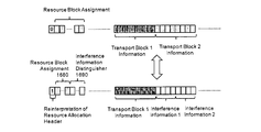
The downlink control information may include a resource block assignment field and can take
any of the following formats:i)the resource block assignment field indicates resource
assignment for the transmission,for which the scheduling information is transmitted;or ii)the
resource block assignment field includes a first subfield(1580)indicating resource assignment
for the transmission,for which the scheduling information is transmitted,and a second subfield
(1590)indicating whether or not the interference information in the second field is to be applied
for interference cancellation for the respective resources specified in the first subfield(1580).
Advantageously,in case of format ii)the second subfield(1690)of the resource block
assignment field indicates for the respective resources assigned in accordance with the first
subfield whether a first interference information or a second interference information is to be
applied to said respective assigned resources,and the second field includes a first subfield
indicating the first set of interference parameters and a second subfield indicating the second set
of interference parameters.
Moreover,within a protocol of a layer higher than the physical layer,a control information may
be provided carrying a transmission mode,wherein the transmission mode can take a value
which defines that the apparatus is to extract from the downlink control information the
interference information as well as values which do not define that the apparatus is to extract the
interference information from the downlink control information.
The decision on whether or not to provide the interference information within the downing control
information may be performed in a transmitter of the DCI(such as the serving base station)
based on measurements of a reference signal,reported to the apparatus by the receiving device
and/or based on load information of an interfering base station.
In accordance with another aspect of the present invention,a computer program product
comprising a computer-readable medium having a computer-readable program code embodied
thereon is provided,the program code being adapted to carry out the present invention.
According to an aspect of the present invention the above apparatus is embodies on an
integrated circuit.
The above objectives and other objectives and features of the present invention will become
more apparent from the following description and preferred embodiments,given in conjunction
with the accompanying drawings in which:
Figure1is a block diagram illustrating an example of physical layer processing of four
services in a digital broadcast system;
Figure2is a schematic drawing illustrating an example of a grid of OFDM modulation
resources in time and frequency domain;
Figures3A to3E are schematic drawings illustrating respective DCI formats2,2A,2B,2C and
2D as used in LTE;
Figure4is a block diagram illustrating interference cancellation at the receiver;
Figure5is a schematic drawing illustrating different interference scenarios for terminals in
the proximity of two base stations;
Figure6is a schematic drawing illustrating mapping of the interference information on a
DCI with format supporting two transport blocks;
Figure7is a schematic drawing illustrating inclusion of interference information into the
DCI depending on the interference conditions of the terminals;
Figure8is a schematic drawing illustrating switching between two formats of the DCI;
Figure9is a schematic drawing illustrating switching between two formats of the DCI by
means of the resource allocation header;
Figure10is a schematic drawing illustrating transmission of interference parameter for
terminals affected by strong interference;
Figure11is a schematic drawing illustrating transmission of interference parameter for
terminals affected by strong interference;
Figure12is a schematic drawing illustrating state transitions for signaling the interference
parameters as shown in Figures9and10;
Figure13is a schematic drawing illustrating transmission of interference information within
a portion of the MCS field of the scheduling information for the second transport
block;
Figure14is a schematic drawing illustrating switching between two formats of the DCI by
means of the redundancy version field;
Figure15is a schematic drawing illustrating utilization of unused resource block assignment
bits in case of lower granularity of resource block assignment;
Figure16is a schematic drawing illustrating utilization of unused resource block assignment
bits in case of lower granularity of resource block assignment for controlling
transmission of plural sets of interference information;
Figure17is a schematic drawing illustrating relation between transmission modes and the
transmission of interference information;
Figure18is a schematic drawing illustrating relation between transmission modes including
a new transmission mode and the transmission of interference information;
Figure19is a block diagram illustrating some apparatuses according to the present
invention;
Figure20A and20B is a schematic drawing illustrating new DCI formats supporting
transmission of interference information.
DETAILED DESCRIPTION
The present invention addresses the support of interference cancellation and suppression by
means of network assistance.Interference cancellation and suppression on the UE side can
significantly increase downlink user throughput due to increased PDSCH SINR.Knowledge of
interference parameters is required on UE side for performing effective interference cancellation
and suppression.The interference may be an inter-cell interference as illustrated on Figure5.
Accordingly,a UE is served by a serving node(e.g.a base station,such as eNB for LTE system)
and is exposed to interference from another node such as another base station controlling
another respective cell.It is noted that the source of interference does not necessarily has to be
a network node such as eNB.Rather,the interference may be generated also by relays or even
by other terminals(especially in the uplink for the LTE),or by parallel transmissions to other
receivers from the serving node itself.
The present invention provides a strategy for transmitting information concerning transmission
parameters used in interfering neighbouring cells and resulting in interference with the
transmission between the victim UEs and the serving node.The victim UEs(UEs subjected to
interference)may use this information for performing interference cancellation or suppression.
It is noted that the term“cellular system”or“cell”refer to any arrangement of a cell including
macro cells,micro cells,pico cells,femto cells or any other concepts.The inter-cell interference
may be also caused by hierarchically organized cells such as a macro cell including an area of a
pico cell.Moreover,for the purpose of the invention,it is considered that a relay(which may also
be a user terminal providing a relay function)coverage may also form a cell.Moreover,the
interference to be suppressed may also be caused by interfering with other terminals.
In the context of LTE,the invention describes different strategies for providing the interference
information together with PDSCH scheduling information for the interference victim UE within a
single downlink control information(DCI)format.This can be achieved by reusing certain bits of
existing LTE Release-11DCI formats or by introducing one or more new DCI formats.
In particular,transmission parameters of the serving eNB are transmitted to the UE in form of
downlink control information(DCI)that is transmitted in physical downlink control channel(s)
(PDCCH)or enhanced physical downlink control channels(E-PDCCH).A possible approach is
to provide the interference information within a DCI format as well.
One approach could be the introduction of a new DCI format that contains only the interference
information from a neighbouring cell(or another interferers).However,using such an approach
would mean that the interference victim UE(UE affected by the interference)has to receive two
PDCCHs or EPDCCHs;one conveying the DCI with the PDSCH allocation information and an
additional one conveying the DCI that contains the interference information.There are two
problems connected with such an approach:(a)the need to receive two PDCCHs or E-PDCCHs
requires additional blind DCI detection and decoding,and(b)the transmission of two PDCCHs
or EPDCCHs results in an increase demand of transmission resources for downlink control
signalling.The latter is given in form of control channel elements(CCE)or enhanced control
channel elements(ECCE)as defined in the LTE specification3GPP TS36.211v12.0.0,
December2013,for instance in Section6.8and Section6.8A.
DCI formats already defined in the LTE specification3GPP TS36.212,v12.0.0,December2013,
Section5.3.3.1,could be extended by bits that are used for the provision of interference
information.The advantage compared to introducing a new DCI would be that no additional blind
detection and decoding of PDCCHs or EPDCCHs is required since both PDSCH allocation
information and interference information are provided within a single DCI format.
However,there are also two disadvantages connected with such an approach:(a)extending the
DCI format size results in a reduced PDCCH or EPDCCH robustness due to increased size,and
(b)the increased DCI format size could result in an increased demand for control channels
elements(CCE/ECCE).The reduced robustness due to reduced channel coding rates form a
critical issue since UEs that are candidates for interference cancellation or suppression are
typically cell-edge UEs that experience low SINR levels.
The problem that has to be solved is the provision of interference information by the serving eNB
in form of L1signalling by meeting following design targets:
-Minimization of additional control overhead:The signalling solution should introduce
as little as possible additional signalling overhead in form of required CCEs/ECCEs.
-Minimum specification and implementation changes:The implied3GPP specification
changes should be kept as small as possible in order to allow a smooth transition to new
specification releases.
-Avoidance of additional DCI blind decoding:The introduction of additional blind
decoding effort for downlink control information should be avoided in order to keep the
UE implementation complexity low.
-Provision of interference information only if required:Interference information should
only be provided to the UE when it is necessary.This requirement correlates with the
need for minimization of control overhead.
According to the invention,the interference information is provided together with PDSCH
scheduling within the same DCI format.
In particular,a method is provided for receiving data from or sending data to a serving base
station in a cellular communication system.The method is performed at a receiving node such
as a terminal and applies blind decoding for identifying and decoding a downlink control
information DCI transmitted by the serving base station.Then,a step of extracting from a first
field of the downlink control information scheduling control information and from a second field of
the downlink control information an interference information is performed.Finally,the receiving
node receives or transmits data on resources specified by the scheduling information while
taking into account the interference information so as to reduce the interference caused by
transmitters other than the serving base station.
Here,the term“blind decoding”refers to decoding of data transmissions without prior knowledge
of corresponding transmissions parameters such as allocated resources and transport format
(i.e.DCI format).In LTE,the number and/or the location of control channel elements(CCEs)
used for the PDCCH transmissions is not known to the terminals in advance.In order to find its
control information,a terminal tries to blindly decode the incoming control information assuming
different combinations of CCEs and checking for the CRC.If the CRC matches,the terminal
concludes that the PDCCH was directed to it and that the control information was decoded
correctly.If the CRC does not match,then the terminal detects another location of CCEs.In
order to keep the number of decoding attempts low,LTE uses a so-called search space for each
terminal.The search space determines the combinations of CCEs that the terminal needs to
monitor for a possible control information.The transmitters other than the serving base station/
network node may be other base stations or relays or even other terminals.
This approach enables reusing bits within DCI formats which exist already in LTE Release-11,
for the purpose of providing interference information to UEs.
The DCI formats that are used for the provision of interference information are the ones that are
used in Release-11for indicating PDSCH allocations with two transport blocks.A transport block
conveys a single code word with individual channel coding.The scheduling of two transport
blocks is used in LTE for transmissions on multiple spatial layers.The mapping of code words to
transport blocks and the mapping of transport blocks to spatial layers is defined in Section
5.3.3.1of the LTE specification3GPP TS36.212v12.0.0,December2013,and Section6.3.3of
the LTE specification3GPP TS36.211v12.0.0,December2013,respectively.
The DCI formats that can be used for scheduling two transport blocks supported by the Release-
11are given below:
-DCI format2:Closed-loop spatial multiplexing or transmit diversity
-DCI format2A:Large delay CDD(cyclic delay diversity)or transmit diversity
-DCI format2B:Dual-layer transmission using antenna port7and8or single antenna
port7or8
-DCI format2C:Transmission on up to eight layers using antenna ports7-14or single
antenna port7or8
-DCI format2D:Transmission on up to eight layers using antenna ports7-14or single
antenna port7or8
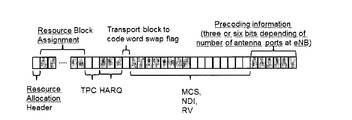
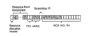
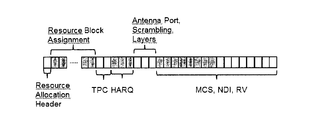
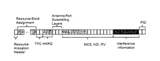
These formats are further illustrated in a simplified manner in the respective Figures3A to3E.In
particular,Figure3A shows that DCI format2includes resource allocation header having a
length of one bit,followed by resource block assignment field(RBA).RBA is a bitmap specifying
for each(group of)PRBs whether the resources are assigned to the controlled node(such as
terminal)or not.The DCI format2further includes a TPC(transmission power commands)
information,HARQ configuration(process number),transport block to codeword swap flag for
assigning the two transport blocks to codewords,and the scheduling information specific for
each of the two transport blocks.The transport block specific scheduling information comprises
eight bits and comprises modulation and coding scheme(MCS)indication,new data indicator
(NDI)and redundancy version(RV)indication.Finally,the precoding information is signalled,
which has a length of three or six bits depending in the number of antenna ports at the eNB and
includes,for instance,rang indicator(RI)or the presiding matrix indicator(PMI).
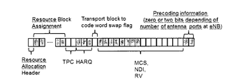
Figure3B shows DCI format2A,which differs from the DCI format2in particular by shorter
precoding information having zero or two bit length,depending in the number of antenna ports.
Figure3C illustrates DCI format2B which includes,apart from the resource allocation header,
RBA,TCP and HARQ information and the scheduling information for the two transport blocks,a
scrambling identity.Figure3D illustrates DCI format2C,,which differs from the format2B in
particular by including information concerning antenna ports,scrambling identity and number of
layers.Figure3E illustrates DCI format2D which,in addition to elements described with
reference to format2C,includes PQI(PDSCH Rate Matching and QuasiCoLocation Indicator)to
inform the UE about the transmitting point or set of transmitting points.
However,it is noted that the present invention is not limited by reusing the existing DCI formats.
A new DCI format may be defined alternatively,with the feature that it includes interference
information within the second field.
According to an embodiment of the present invention,the scheduling information extracted from
the first field of the downlink control information is a first scheduling information which indicates
transmission parameters for a first transport block of data.The second field includes either the
interference information or a second scheduling information which indicates transmission
parameters for a second transport block of data.
Thus,in terms of LTE,a UE can be scheduled
-either for a PDSCH transmission with two transport blocks.Here it is assumed that the
interference is negligible,i.e.the UE is out of the area500illustrated in Fig.5.
-or for a PDSCH transmission with a single transport block in combination with providing
interference information to the receiving UE.
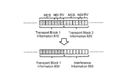
Figure6shows how the bits for one of the two transport blocks within a DCI format are used for
providing interference information.The interpretation of the remaining bits of the DCI format is
not changed.In particular,Figure6shows the contents of the first field610of the downlink
control information.The first field610carries scheduling information for the first transport block.
The scheduling information contains modulation and coding scheme,new data indicator and
redundancy version.The contents of the second field620includes the same type of scheduling
information(MCS,NDI,RV)for the second transport block.Thus,the first field610and the
second field620correspond to the current LTE DCI format.This format is advantageously
further applied for terminals which experience rather low interference,e.g.interference which
does not exceed a predefine threshold.If the terminals experience a high interference,e.g.
interference exceeding certain threshold,the format of the DCI’s in this embodiment
corresponds to the first field630and second field650.Similarly to the first field610,the first field
630includes scheduling information for the first transport block.The length of the fields610,620,
630,and640is the same.However,the second field650does not include the information
related to the second block,but rather the interference information for the receiving device.The
interference information enables the receiving device to perform estimation of the interference
and thus,to cancel or suppress the interference as illustrated in Figure4.
The effect of this approach is that a UE can only be provided with interference information if a
single transport block is scheduled.If two transport blocks should be scheduled for the UE,
interference information is not provided.
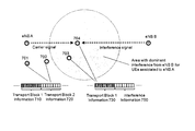
Figure7shows the application of the basic concept in a typical NAICS scenario with inter-cell
interference.The figure shows four different UE positions(701,702,703and704)where UEs at
positions701and702do not experience strong inter-cell interference,while UEs at positions
703and704are affected by strong interference.Since efficient interference cancellation or
suppression of high interference power levels depends on the ability to obtain accurate
interference estimations(I’in Figure4),it is reasonable to provide interference information only
to UEs at positions703and704.For UEs at positions701and702,interference information is
not required since the interference power level is very low and does hence not justify the use of
interference cancellation,which requires additional computational capacity and thus also power.
The implied restriction of the present embodiment,namely that UEs at positions703and704
cannot be scheduled for two transport blocks,is not expected to affect the system performance
in a negative way.The scheduling of two transport blocks is used in LTE for transmissions on
multiple spatial layers.Transmissions on multiple spatial layers are most beneficial in case of
high SINR level,which corresponds to UEs located in the proximity of the cell-centre and thus
experience low interference power levels.On the other hand,the UEs located in the proximity of
the cell edges experience high interference power levels and would thus rather be scheduled
with single layer transmission in order to maximize the SINR.
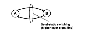
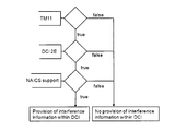
Figure8shows an example of switching between DCI format interpretation states.In particular,
Figure8illustrates that the downlink control signalling for a UE configured for NAICS support
can therefore be described by two states:state A in which DCI scheduling information is
provided for two transport blocks and without interference information(610,620),and state B in
which DCI scheduling information is provided for a single transport block630and in addition,the
interference information650is included.
There are different options for switching between these two configurations A and B.For instance,
the switching may be performed by means of higher-layer signalling or by means of a dynamic
indication within DCI formats.
In the first of these embodiments,the switching message is received on a protocol layer higher
than the physical layer,and the switching message indicates the format of the second field,
namely whether or not the second field is to carry the interference information.It is noted that the
switching message may have any format,which enables to indicate whether or not the
interference indication is to be included in the DCI.For instance,the switching message can be
transmitted only if the DCI format(in particular,the fact whether or not the DCIs for the particular
UE are to include the interference information)changes.For instance,such switching message
may be transmitted if the interference conditions of the receiving device change.The change
may correspond to increase of the interference,so that it becomes useful/necessary to transmit
the interference information.The change may also correspond to decrease of interference,so
that it becomes unnecessary to transmit the interference information.
However,it is noted that the present invention is not limited to reusing the old DCI format.There
may be a new DCI format,which includes the interference information.Such new DCI format
may beneficially include information for a first transport block and the interference information as
illustrated in Figure6(630,650)and not include information for a second transport block.This
enables definition of a new DCI with similar field sizes as the currently used DCIs.The dynamic
switching between both states could be indicated by a new additional bit in the DCI format.
However,the new DCI may also have a different format.For instance,the interference
information may be added to the DCI.Accordingly,the DCI may include the scheduling
information relating to both transport blocks and in addition thereto a new field for carrying the
interference information(interference parameters).It is noted that such additional interference
information field may have any size,in accordance with the interference parameters to be
transmitted.The size may be fixed with a predefined number of bits.With the new DCI defined,
the switching would not require dynamic switching since scheduling information for two transport
blocks and interference information can be provided within the same DCI format.
Figure8illustrates an embodiment of the present invention,according to which the switching
between the two states A and B is performed in a semi-static fashion by means of a higher-layer
signalling,e.g.by means of MAC or RRC messages.For the switching message,a new element
may be added into an already defined MAC or RRC message.For instance,RRC Connection
Reconfiguration described in Section5.3.5of1of the LTE specification3GPP TS36.331
v12.1.0,March2014.Alternatively,a new MAC or RRC message could be defined for indicating
NAICS support by the serving eNB.
The decision on state change can be made for example based on reference signal received
power(RSRP)or RSRQ measurements of neighbouring cells.RSRP is a linear average of
reference signal power over a specified bandwidth.It is usually measured by the UE for the
purposes of cell selection,reselection and handover.The UE measures the power of the pilot
signals(reference signals transmitted with a predefined power).The measurement result is
reported to the serving node.The RSRQ measurement provides additional information and is
the ratio between the RSRP and the Received Signal Strength Indicator(RSSI),and depending
on the measurement bandwidth,means the number of resource blocks.RSSI is the total
received wideband power including all interference and thermal noise.As RSRQ combines
signal strength as well as interference level,this measurement value provides additional help for
mobility decisions as well as a mean for roughly estimating the interference level.RSRQ
measurement results are also signaled to the serving node.Details to RSRP and RSRQ can be
found in the LTE specification3GPP TS36.214v11.1.0,December2012,Section5.1.1and
Section5.1.3,respectively.Accordingly,the measurements provided by the receivers of the DCI
information to the serving node(serving base station)may be used to make the decision on
whether or not the DCI shall include interference parameters.According to the decision
performed at the serving node,the serving node then transmits the switching message to the
respective DCI receivers.It is noted that RSRP and RSRQ are only examples from the LTE.
However,the present invention is not limited to these examples.In general,any measurements
reported to the serving node from the DCI receivers reflecting the interference conditions of the
DCI receivers can be used.
Alternatively to signalling the DCI format including or not the interference information via higher
layer signalling,dynamic switching by means of L1signalling between the provision of
scheduling information for two transport blocks(state A)without interference information and the
provision of scheduling information for a single transport block plus interference information
(state B)is envisaged according to another embodiment of the invention.
Accordingly,a switching indication on the physical layer is provided,wherein the switching
indication indicates the format of the second field,namely whether or not the second field is to
carry the interference information.The switching indication lay be signalled directly within the
corresponding DCI.
In particular,the switching between the two states A and B(i.e.the format of the second field in
the DCI format to be applied)is indicated within the DCI format itself.This can be achieved by
either introducing a new bit that will be used for indicating the state,or by assigning for this
purpose a bit within the existing DCI format(s).
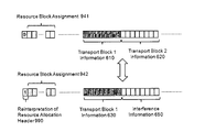
Figure9shows the reuse of resource allocation header of DCI formats2,2A,2B,2C and2D.
The resource allocation header in these DCI formats is currently used in Release-11LTE for the
purpose of switching between two allocation types:
-Type0:A bitmap indicates resource block groups(RBGs)that are allocated to the
scheduled UE.RBGs consist of respective sets of consecutive physical resource blocks
(PRBs).
-Type1:Individual PRBs can be addressed within a subset of PRBs.The bitmap is
slightly smaller than for Type0since some bits are used to indicate the subset of PRBs.
The motivation for providing this method of resource allocation is flexibility in spreading
the resources across the frequency domain to exploit frequency diversity.
As described above,resource allocations according to Type1are used in order to better exploit
frequency diversity.This can be seen as a strategy for addressing inter-cell interference,as well.
However,regarding the interference information required for effective interference cancellation
or suppressions,this allocation scheme is rather counterproductive since spreading the PDSCH
over a large part of the frequency channel will most likely result in a minimum correlation
between the interference parameters of different PRBs which cause interference to the
considered PDSCH.It would require hence a rather large amount of interference parameter
signalling overhead if blind detection of these parameters is not possible.In terms of interference
parameter provision,resource allocation based on Type0is thus more beneficial due to the
allocation granularity of groups of consecutive PRBs.
Accordingly,the restriction to resource allocation of Type0for a DCI format with single transport
block allocations plus provision of interference information is not expected to constitute any
negative impact on the PDSCH throughput performance.
The application of the dynamic indication of interference information provision is shown in
Figures10and11for the case with high and low traffic load in the interfering eNB B,
respectively.In particular,Figure10shows terminals1001and1002which do not experience
high interference.Terminals1003and1004are within the area with dominant interference from
the eNB B.Thus,it is beneficial when terminals1003and1004are provided with interference
parameters corresponding to the transmission configuration of the eNB B in order to be able to
estimate the interference and apply interference cancellation.Thus,terminals1001and1002
are provided with scheduling information concerning two transport blocks1010and1020.The
resource allocation header1091is applied as envisaged in current Release-11LTE,namely to
signal Type0or Type1as explained above.In contrast,since terminals1003and1004require
transmission of interference information,they are provided with DCI including scheduling
information for only one transport block1030and with interference parameters1050.This
interpretation of the first and second field is signalled by setting the resource allocation header
1092to1.
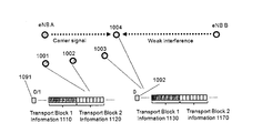
Figure11shows a case in which the interference from the eNB B is not significant,so that
terminals1003and1004also do not require the provision of interference information.Thus,the
DCI for terminals1003and1004includes resource allocation header set to0meaning that the
first field1130as well as the second field1170carry scheduling information related to the
respective transport blocks.In the examples of both Figure10and Figure11it is assumed that
terminals1003and1004apply Type0allocation.However,the allocation may be set freely to
Type0or Type1for the terminals1001and1002.
UE1001and UE1002are not configured for NAICS support since they are not expected to
experience strong interference from eNB B(e.g.based on RSRP measurements as described
above)even in case of high traffic load.These UEs can always be scheduled with two transport
blocks resource and resource allocation based either on Type0or Type1.
UE1003and UE1004are potential interference victims of eNB B in case of high traffic load in
the corresponding cell.The fact that these UEs are potential interference victims can for
example be determined by means of RSRP measurements as described above for the higher
layer signalling example.UE1003and UE1004are therefore configured for NAICS support.
According to one embodiment of the invention,this means that PDSCHs for these UEs can only
be scheduled with resource allocation Type0and the DCI format provides either scheduling
information for two transport blocks or scheduling information for a single transport block plus
interference information.
For UE1003and UE1004,two transport blocks can be scheduled if the SINR level is high due
to low traffic load at eNB B,assuming it is the dominant cause for interference.The serving
eNB A can be informed about the traffic load at eNB B via backhaul signalling between both
eNBs,for example by a corresponding extension of the X2interface defined in the LTE
specification3GPP TS36.432v12.1.0,March2014.If the traffic load is high,the UE could be
scheduled for single transport block transmissions in combination for the provision of
interference information.
The dynamic switching between the two possibilities for UE1003and UE1004is beneficial in
case of fast fluctuations of the traffic load which is for example prevailing in case of FTP traffic
assumptions.The downlink control signalling for a UE configured for NAICS support can
therefore be described by three states:state A with no provision of interference information and
possible scheduling of two transport blocks with resource allocation based on Type0and Type1;
state B1with scheduling of two transport blocks with resource allocation based on Type0
without interference information;and state B2with scheduling of a single transport block with
resource allocation based in Type0and with interference information.
The corresponding state model is illustrated in Figure12.The switching between state A and
state B(with sub-states B1and B2)is performed in a semi-static fashion by means of higher-
layer signalling.For instance,by means of RRC Connection Reconfiguration described in
Section5.3.5of1of the LTE specification3GPP TS36.331v12.1.0,March2014.The switching
between sub-states B1and B2is performed in a dynamic fashion by means of an indication
within the DCI format as described in this invention.
In summary,the switching indication is received in this embodiment within a3GPP LTE
Release-11downlink control information message,in the resource allocation header field,while
it is assumed that Type0allocation applies.Moreover,the resource allocation header
interpretation is configured semi-statically by a layer higher than the physical layer,wherein the
resource header is interpretable either as indicating Type0or Type1allocation or as indicating
the switching indication.The higher layer signalling may be MAC or RRC.
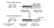
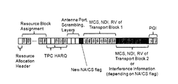
Figure13illustrates another alternative to the approach illustrated in Figures11and12.In
particular,Figure13shows a variant for the dynamic switching between providing interference
information or not,by means of reinterpretation of the resource allocation header bit in the DCI
format2,2A,2B,2C or2D of Release-11LTE.The scheduling of two transport blocks in this
alternative is possible even in combination with the provision of interference information.As can
be seen in Figure13,the dynamic switching may be applied also in this embodiment.However,
it is noted that the format of the second field1350,1370as shown in Figure13may also be
applied without dynamic switching.The switching may be semi-static by higher layer protocols.
In Figure13the scheduling information extracted from the first field of the downlink control
information is a first scheduling information1330which indicates transmission parameters for a
first transport block of data.The second field of the downlink control information includes either
the interference information1350together with a reduced second scheduling information1370
which indicates transmission parameters for a second transport block of data or only a complete
second scheduling information which indicates transmission parameters for a second transport
block of data.
Advantageously,the first and the second field have the same sizes,each of the first and the
second field includes a modulation and coding scheme subfield for indicating modulation and
coding scheme(MCS),and the modulation and coding scheme subfield of the first field is larger
than the modulation and coding scheme subfield of the second field.Thus,the MCS field is
reduced in order to enable within the same DCI to signal both,the interference parameters and
the information concerning second transport block.It is noted that shortening the MCS is nly an
example.In general,any information such as RV may be shortened alternatively or in addition to
the MCS field.
However,in this embodiment the scheduling flexibility of Transport Block2is reduced;the
original allocation of five bits for indicating the modulation and coding scheme(MCS)is reduced
fraction of these five bits(e.g.two bits in the example shown in13).This reduced number of bits
for the MCS indication could for example be used for indicating the MCS level by means of
differential indication compared to the MCS level of Transport Block1assuming the same MCS
table for Transport Block1and Transport Block2as defined in Section7.1.7of the LTE
specification3GPP TS36.213v12.0.0,December2013..Two bits for the differential MCS
indication would support four levels and three bits would support eight levels.More bits for the
differential would provide even more flexibility,but the benefits are expected to be negligible.
The drawback of this approach compared the scheme described with reference to Figures10to
12is that the number of bits that can be used for the provision of interference information is
reduced.To which extend this affects the system performance depends on the amount of
required interference information in the UE receiver;the more interference information is
required,the more bits are required in the corresponding DCI as well and the more serious is the
reduction of the MCS range.
Figure14shows another variant for the dynamic provision of interference information within DCI
format2,2A,2B,2C and2D.In contrast to the schemes described above with reference to
Figures10to13,the switching between DCI format interpretations is not indicated by the
reinterpretation of the resource allocation header bit,but by a certain code point of the
redundancy version(RV)field for Transport Block2.Figure14shows on the top the
transmission of the DCI with the scheduling information1410for the first transport block and the
scheduling information1420for the second transport block.The last two bits of the scheduling
information1420are formed by redundancy version which thus may take values00,01,10,and
11.Since the RV in the field1420has a value different from a predefined value(here the
codepoint01),the field1420is interpreted as the scheduling information for the second
transport block.On the bottom of Figure14,the redundancy version1480of the second field
1450has the value of01,which corresponds to the predefined value and indicates in this
embodiment that the second field1450is to be interpreted as interference information and not
as the scheduling information for the second transport block.
In other words,in this embodiment,the switching indication is signalled within the second field
in that at least one codepoint among all possible values defined by a subset of bits of the second
field indicates that the interference information is transmitted in the second field and all
codepoints other than said at least one codepoint indicate that the interference information is not
transmitted in the second field.As shown in Figure14,the subset1480of bits can take either
the value of said at least one codepoint(e.g.10in1450)or another value indicating redundancy
version for the second transport block(e.g.RV in1420).However,it is noted that usage of the
redundancy version is only an example.In general,a codepoint of another subset of bits of the
second field1450may be taken for signaling the presence of the interference information.For
instance,one or more codepoints may be reserved for this purpose in the modulation and coding
scheme field MCS.This may be also the case in the embodiment described with reference to
Figure13,for the reduced MCS field.In such a case,the resource block header in Figure13
would not need to be reinterpreted and could be used in its usual meaning at any interference
conditions.Further combinations of these two embodiments are possible as is clear to those
skilled in the art.
The RV field is used in LTE Release-11for selecting different redundancy versions of a code
word for HARQ transmissions;four different redundancy versions are supported and may be
employed as in the present embodiment.In order to allow dynamic switching between the
allocation of two transport blocks without interference information and a single transport block
with interference information within the DCI,a certain RV field code point(e.g.01in Figure14,
but generally any of the points00,11,01,11)of Transport Block2could be used for indicating
the provision of interference information instead of scheduling information for Transport Block2.
The advantage of this approach is that resource allocation can be performed based on both
Type0and Type1.The implied restriction is that a certain redundancy version cannot be
scheduled for Transport Block2.Compared to the solution described with reference to Figures
10to12,the number of bits that can be used for providing interference information is
furthermore reduced from eight bits to five bits.
Another variant of the present invention is shown in Figure15.Accordingly,parts of the resource
block allocation(RBA)field of the DCI are reused for indicating the interference resource
allocation that adheres to the interference parameter information provided in the bit field for
Transport Block2.It is noted that the term“switching indication”does not necessarily mean that
the indication indicates change of the format.As shown in the above examples,the switching
indication may indicate the format applicable(switched)for the current DCI.However,the
present invention is not limited thereto and the switching indication may also indicate whether
the format is to be changed or not.The same applies for the switching message transmitted by
higher layers and described above.
In LTE Release-11,assuming that the resource allocation is based on Type0,the RBA field of
the DCI represents a bitmap that indicates the set of resource block groups(RBGs)which are
allocated for the PDSCH transmission indicated in the DCI.An RBG constitutes a set of
consecutive physical resource blocks(PRBs),and the RBG size,which may be1,2,3or4
PRBs,depends on the downlink bandwidth as shown in the following Table1:
Table1:RBG size for Type0resource allocation
Table1shows furthermore how the resource allocation granularity would be reduced for
resource allocations to an UE that is configured for NAICS support.The reduced allocation
granularity entails the possibility to use a bitmap with half the size of the original RBA field in the
current DCI for allocating PRBs for PDSCH transmissions.The other half of the RBA field is
used for indicating the resource block allocation of the interference transmission that adheres to
the provided interference parameter information by means of an interference resource allocation
bitmap.
In particular,Figure15shows reinterpretation of resource allocation header as described above
for distinguishing whether or not the interference information is transmitted with the current DCI.
However,this embodiment may also be applied without dynamic indication by means of higher
layer configuration so that the resource allocation header maintains its usual meaning.Moreover,
the present embodiment may also be combined with the previous embodiments described with
respect to Figures13and14.Thus,the switching indication may be transmitted within the
second field and/or the second field may include both the interference information as well as the
scheduling information.According to Figure15,the resource allocation header with length of one
bit is followed by resource block assignment(RBA)field.The top part of Figure15shows RBA
field as currently used in LTE.The bottom part of Figure15illustrates an example in which the
RBA field includes a first subfield1580for carrying the allocation block assignment for the
transmission defined further in the first field(“Transport Block1Information”in the figure)and a
second subfield1590for carrying Interference Resource Block Assignment,i.e.a bitmap in
which for each resource group pair(cf.table1above with the granularity resulting in resource
group pairs of2,4,6or8PRBs)a corresponding bit indicates whether the interference
information transmitted in the second field is to be applied or not.For example,a first bit of the
Interference Resource Block Assignment1590may refer to the same resources to which the
first bit of the bitmap concerning the resource block assignment1580is related.The first bit of
1590may take value0which can indicate that the interference information is not to be applied
for interference cancellation on the resources addressed by the corresponding first bit of the
resource block assignment1580.It can also take value1which indicates that the interference
information is to be used for the respective resources.
In general,the resource block assignment field includes a first subfield1580indicating resource
assignment for the transmission,for which the scheduling information is transmitted,and a
second subfield1590indicating whether or not the interference information in the second field is
to be applied for interference cancellation for the respective resources specified in the first
subfield1580.Accordingly,an interference cancellation unit in the transceiver of the DCI
receiving apparatus may be controlled by the interference resource block assignment1590(i.e.
by the second subfield)to apply or not interference cancellation for the respective resources
addressed by the bits of the first subfield.
Another option is that the interference resource allocation bitmap is used for distinguishing two
different sets of interference parameters in the interfering cell per resource allocation unit;the
latter is determined based on the resource allocation granularity for NAICS given in Table1.
The bit field for Transport Block2could then be separated into two parts;one for indicating
interference parameters of the first set,and a second one for indicating interference parameters
of the second set.The concept is depicted in Figure16.In particular,the top part of Figure16
corresponds to the top part of Figure15.The bottom part shows the resource block assignment
field which includes two subfields1680,1690.A first subfield1680corresponds to the subfield
1580described with reference to Figure15,it indicates the resource block assignment.In
particular,the first subfield1580carries a bitmap with each bit indicating whether a respective
resource portion is assigned or not.The size of the portion addressed by one bit is given by the
RBG size and the granularity applied in the NAICS mode.In the case of Table1,row2for
instance,each bit would refer to two RBGs,each of which consisting of two PRBs.
The second subfield1690of the resource block assignment field is an Interference Information
Distinguisher and indicates for the respective assigned resources whether a first or a second
interference information included in the second field is to be applied for the respective assigner
resources.Moreover,the second field of the scheduling information carries two sets of
interference information(“Interference Information1”and“Interference Information2”).Based on
the Interference Information Distinguisher1690received within the DCI,the interference
cancellation unit,part of a transceiver of the DCI receiving apparatus,applies either interference
information1or interference information2for the purpose of interference estimation.
For instance,the first interference information may include a first set of interference parameters
applicable to a CRS based transmission(of the interferer)and the second information may
include a second set of interference parameters applicable to DMRS based transmission.The
Cell-Specific Reference Signals(CRS)and Demodulation Reference Signals(DMRS)are
reference signals used in LTE.In a CRS based transmission,the CRS is merely a reference
signal,so that no information on precoding is available based on CRS.Accordingly,the
precoding information(such as precoding matrix and rang indicator)is to be transmitted
separately.Since the precoding information related to the interferer(such as eNB B)also
improves the estimation of interference,it makes sense when the first interference parameter set
also includes the precoding information.DMRS is a reference signal which also carries
information about the precoding and in particular the phase resulting from the applied precoding
matrix of the data transmitted.Accordingly,for the DMRS based transmission,no information
concerning precoding is necessary.Accordingly,the second set of interference parameters
advantageously does not include the precoding parameters.
However,it is noted that the example with DMRS-based transmission and CRS-based
transmission by the interferer is only one of possible embodiments of the invention.The
interference sets may also be structured in another way.
This structure of the RBA field in the above embodiments is provided while assuming that the
resources are only assigned in couples when the interference information is transmitted in the
DCI.Accordingly,only a half of the originally available range for RBA is necessary to indicate the
allocation in such scenario.In particular,Table1shows that RBGs have1,2,3or4PRBs but
the resources may be only assigned for twice as much PRBs,i.e.for2,4,6or8PRBs.This
corresponds to granularity reduced by factor2.In general,the granularity of the resource
allocation may be even more restricted than the restriction of Table1.For instance,the
granularity may be reduced by factor3.This would result in the values of last column in Table1
of3,6,9and12PRBs.
Accordingly,the embodiment described with reference to Figure16can be further extended by
providing more sets of interference parameters in the respective more subfields of the second
field.This would be enabled for higher granularities.Correspondingly the resource block
assignment would include the first subfield for resource assignment and then a second subfield
with2or more bits for indicating the set of interference parameters to be applied.
It is not expected that the reduced resource allocation granularity will have negative performance
impacts.This assumption is motivated by the fact that the CQI reporting granularity for sub-
bands that are configured by the eNB is already lower than the allocation granularity in case of
aperiodic reporting,as shown in the following Table2:
Table2:Sub-band size for aperiodic CQI reporting
Applying the above concept described with reference to Figure15and16would basically align
the allocation granularity to the reporting granularity.A precondition for applying this variant of
switching indicator signalling shown in Figures15and16is that the resource allocation in the
interfering cell is based Type0with reduced allocation granularity as well.
Instead of switching the state of the DCI format by reinterpreting the resource allocation header,
variant C could also be combined with the state switching based on the RV field interpretation
described above with reference to Figure14.It could furthermore be combined with the reduced
MCS concept described with reference to Figure13.
The proposed signalling concept for the provision of interference information addresses all the
above described design targets in an efficient manner.
-Due to the reuse of bits that are common to DCI format2,2A,2B,2C and2D,the
provision of interference information can be provided in combination with a large variety
of different transmission schemes.It allows therefore a significant degree of freedom of
transmission schemes for UEs that makes use of NAICS support.
-The reliability of DCI transmissions in terms of error rates is not affected by the provision
of interference information since the DCI format size is not extended.
-Additional blind decoding of PDCCHs is not required since interference information is
provided together with PDSCH scheduling information within the same DCI format.
-The interference information is provided by means of reusing bits within a DCI format that
will most likely anyway not be used for scheduling PDSCHs for UEs that can benefit from
interference cancellation or suppression.
-In addition to semi-static configuration of NAICS support,the proposed signalling concept
furthermore allows for fast switching between provision of interference information and
possibility to schedule two transport blocks.
The interference parameters that could be provided to the UE within the DCI format could be a
subset of the parameters described above.This could be for example be a simple indication
whether PDSCH transmission are scheduled for reception based on DMSR or CRS in the
interfering eNB;in case of the CRS based transmission,the corresponding PMI(precoding
matrix indicator)and RI(rank indicator)could be indicated as well within the interference
information since the precoding of the PDSCH is given by a code book entry given by PMI and
RI,and the CRS as reference for the precoding.PDSCH receptions based on DMRS do not
require the indication of a precoder(e.g.based on a code book)since the UE directly
determines the precoder by measuring the DMRS.It could furthermore be reasonable to indicate
the modulation order used on the interfering PBRs.
In addition to explicitly indicating certain interference transmission parameters such as PMI and
RI it is also possible to indicate certain predefined sets of interference parameter combinations.
The determination of the exact interference parameters would then be determined by means of
blind detection on a reduced set of hypotheses.The benefit would be a reduced blind detection
complexity.
It is furthermore possible to either provide interference information only from a single
neighbouring eNB(e.g.determined based on RSRP measurements on UE side),or from a set of
neighbouring eNBs.
The question which interference parameters can be determined by means of blind detection and
which required support from network side in form of indication by means of downlink control
signalling is still under discussed at3GPP RAN1and RAN4.Details of the current discussion
status can be found in the NAICS technical report and NAICS working item cited above.
A precondition for indication interference parameters to the interference victim UE without
additional information on the PRB allocation of the interference together with the PDSCH
allocation for that UE in the same DCI is the assumption that the interference allocation in terms
of allocated PRBs coincides with the PRB allocation of the interfered PDSCH.This can be
achieved by coordinated resource allocation between neighbouring eNBs,for example by means
of scheduling restrictions as they are currently discussed at3GPP RAN1within the scope of
NAICS.More flexibility in the resource allocation of the interfering cell can be facilitated by
utilizing the concept described with reference to Figures15and16.
It is noted that the present invention is not limited to Release-11LTE.It is applicable to any
communication system in which the terminals served by a base station may suffer interference
from other transmitters.Nevertheless,the present invention may readily be applied to the3GPP
LTE.Accordingly,in the following,some more details are provided for incorporating the present
invention into the existing parts of the standard.In order to embody the present invention into the
existing provisions of the standard,Transmission Modes defined in Release-11may be used.
Figure17shows a flow chart describing the PDSCH allocation in combination with providing
interference information for Release-11transmission modes that support scheduling of two
transport blocks;which are TM3,TM4,TM8,TM9and TM10as described in3GPP TS36.213
v12.0.0,December2013,Section7.1.In LTE,a UE is configured for a single transmission mode
per cell.Each of the transmission modes supports two transmission schemes that are
distinguished by blind detection of the DCI format used for providing PDSCH scheduling
information to the receiving UE.The DCI formats that are used for scheduling two transport
blocks are DCI format2,2A,2B,2C and2D corresponding to TM4,TM3,TM8,TM9and TM10,
respectively.The transmission mode is provided to the UE in an RRC message whenever the
UE establishes an RRC connection which may be an initial connection to an LTE network or a
reestablishment of an RRC connection.
The second supported DCI format of all considered transmission modes is DCI format1A which
is used for scheduling PDSCH transmissions by means of transmit diversity as described in
3GPP TS36.213v12.0.0,December2013,Section7.1.The provision of interference
information(NAICS support)is only supported in the DCI format2,2A,2B,2C and2D.Whether
one of these DCI formats contains interference information is indicated to the receiving UE either
by semi-static configuration based on higher-layer signalling or by dynamic indication within the
DCI format itself.Figure17thus illustrates the rules for generating/parsing the DCI.If the
transmission mode is TM3,4,8,9or10(i.e.transmission mode supporting DCI formats for
transmission of two transport blocks),then it is tested whether such DCI format is included.If the
transmission mode is other than TM3,4,8,9or10,inclusion of the interference information is
not possible.If the DCI format is not a format2,2A,2B,2C or2D,i.e.a format with a first and a
second field related to transmission of two transport blocks,then the inclusion of the interference
parameters is also not possible.However,if the DCI format is one of the2,2A,2B,2C or2D
formats,then it is to be tested whether NAICS support is enabled.If not,then the interference
information cannot be included into the DCI.If the NAICS is supported,then any predefined of
the possibilities of including the interference information into the DCI as described above may be
applied.
Figure18shows an alternative flow chart considering the definition of a new transmission mode
(i.e.TM11)for the provision of the interference information.Corresponding to the Rel-11
transmission modes TM3,TM4,TM8,TM9and TM10,this new transmission mode could be
used for scheduling two transport blocks without providing interference information or for
scheduling a single transport block in combination with providing interference information as
described in any of the above embodiments.The dynamic switching between both states could
be indicated by a particular bit(e.g.NAICS flag)in the new DCI format(i.e.DCI format2E).
In summary,all UEs are configured with a transmission mode to help it determine how to
process data transmissions received on the Physical Downlink Shared Channel(PDSCH).
According to an embodiment of the present invention a transmission mode(an interference
transmission mode)is defined in accordance with which the terminal is configured to extract
from the DCI the interference information.The extraction may be conditioned by a switching
indication,i.e.once the UE is in the interference transmission mode,then the UE checks
whether the switching indication indicates to extract or not to extract from the DCI the
interference information and handles accordingly.
Another option corresponding to an embodiment of the invention is to introduce a new bit field
for interference information within the new DCI format(i.e.DCI format2E).Such a DCI format
could then always allow the allocation of two transport blocks in combination with provision of
interference information.Examples of new DCI formats in accordance with an embodiment of
the invention are illustrated in Figure20A and20B.
Figure20A shows a DCI format2E based on the format2D described above with reference to
Figure3E.Format2E differs from the format2D in particular by additionally including an
interference information field.Thus,the exemplary format2E is longer than the format2D.
Format2E can be used always when the interference transmission is to be transmitted
(conveyed).Accordingly,the application of the format2E already indicates that the interference
information is transmitted.For transmission of control information without interference
information,another format such as2D would be used.
Figure20B shows another possible new DCI format2F which may be defined alternatively or in
addition to the format2E described above.Format2F is also based on format2D described
above with reference to Figure3E.However,in addition thereto,it includes a new NAICS flag
which indicates whether the second field(“MCS,NDI,RV of Transport Block2or Interference
Information”)carries the interference information or the scheduling information for the second
transport block.This flag thus indicates whether the network assisted interference cancellation
and suppression is applicable at the receiver of the DCI.
It is noted that both above exemplified new DCI formats2E and2F are based on the existing
format2D.However,the present invention is not limited thereto any of the formats2,2A,2B,2C
or2D described with reference to Figure3may be adapted in a similar way.The advantage of a
new DCI is that the resource allocation header may be used for its original purpose of signalling
type0or type1resource allocation,irrespectively of interference situation and that also the
other fields of the DCI may serve their usual purposes(such as redundancy version or MCS).
However,the new DCI formats are slightly longer(format2E includes the interference
information in addition to the scheduling information of the two transport blocks,format2F
includes at least one more bit for the NAICS flag).It is noted that the length of the interference
information in the new DCI formats,especially the format2E does not have to match the length
of the scheduling information.Any length necessary for signalling of the interference parameters
or their subset as described above may apply.
The definition of a new transmission mode(such as TM11)for providing interference information
to the receiving UE has the advantage that it is possible to define a new DCI format that can be
optimized for the provision of interference information in terms of required number of bits and
supported degrees of freedom for the PDSCH allocation in the serving cell;in contrast to the
approaches described with reference to Figures13to16,the new DCI format could for example
always allow the allocation of two transport blocks with both Type0and Type1resource
allocation plus indicating interference information.
The disadvantage of such an approach is that the size of the DCI format is increased which
results in reduced robustness and increased demand for control channel resources.Another
issue is that the NAICS support in terms of providing interference information to the UE that is
scheduled for a PDSCH is only supported for a single transmission mode(such as the TM11)in
contrast to the approaches without limiting the possibility of transmitting the interference
information to a separate new transmission mode,where multiple transmission modes are
supported.
In general,the provision of interference information together with PDSCH scheduling information
within a single DCI format does not have to be restricted to a single new transmission mode and
corresponding DCI format.Multiple transmission modes and corresponding DCI formats could
be defined for NAICS support in order to feature more scheduling flexibility for the serving eNB.
Figure19is a block diagram illustrating a control information receiver1902and a control
information transmitter1901for embodying the above described functionality.In particular,the
apparatus1902for receiving control data from a serving base station in a cellular
communication system comprises a blind decoding unit1910for identifying and decoding a
downlink control information(DCI)transmitted by the serving base station1901;an extraction
unit1920for extracting from a first field of the downlink control information decoded a scheduling
control information and from a second field of the downlink control information an interference
information;and a transceiver1930for receiving or transmitting data on resources specified by
the scheduling information while taking into account the interference information so as to reduce
(in the interference cancellation unit1935)the interference caused by transmitters other than the
serving base station.Moreover,a control unit1940may serve for controlling the extraction unit
to extract from the second field the interference information or scheduling information for the
second transport block.The apparatus1902may be a terminal such as mobile terminal or any
other device connected to the network via serving base station1901over wireless.
The apparatus1901for transmitting control data to a receiving device1902in a cellular
communication system may be a serving base station(eNB A)for the receiving device1902and
comprises:an interference information determining unit1970for determining the interference
experienced by the receiving device1902caused by transmitters other than the serving base
station(eNB B);a control information generation unit1960for generating a downlink control
information including a first field including a scheduling control information and a second field
including the interference information;and a transceiver(1950)for transmitting to the receiving
device for blind decoding the generated downlink control information,and for receiving or
transmitting data from/to the receiving device on resources specified by the scheduling
information.The apparatus may further include control unit1980which may perform judgement
on whether to generate and include or not the interference information into the downlink control
information.This judgement may be based on the measurements received by the base station
1901from the terminal1902and/or based on the load of the interfering base station if the
interference is caused by another base station.The load information may be conveyed to the
serving base station by means of a backhaul link between the serving and the interfering base
station.
The explanations given in the Technical Background section above are intended to better
understand the specific exemplary embodiments described herein and should not be understood
as limiting the invention to the described specific implementations of processes and functions in
the mobile communication network such as a network compliant with the3GPP standards.
Nevertheless,the improvements proposed herein may be readily applied in the
architectures/systems described in the Technological Background section and may in some
embodiments of the invention also make use of standard and improved procedures of theses
architectures/systems.It would be appreciated by a person skilled in the art that numerous
variations and/or modifications may be made to the present invention as shown in the specific
embodiments without departing from the spirit or scope of the invention as broadly described.
Another embodiment of the invention relates to the implementation of the above described
various embodiments using hardware and software.It is recognized that the various
embodiments of the invention may be implemented or performed using computing devices
(processors).A computing device or processor may for example be general purpose processors,
digital signal processors(DSP),application specific integrated circuits(ASIC),field
programmable gate arrays(FPGA)or other programmable logic devices,etc.The various
embodiments of the invention may also be performed or embodied by a combination of these
devices.
Further,the various embodiments of the invention may also be implemented by means of
software modules,which are executed by a processor or directly in hardware.Also a
combination of software modules and a hardware implementation may be possible.The software
modules may be stored on any kind of computer readable storage media,for example RAM,
EPROM,EEPROM,flash memory,registers,hard disks,CD-ROM,DVD,etc.
The present invention relates to transmission and reception of downlink control information in a
communication system.In particular,a serving base station transmits to a terminal a downlink
control information which includes a first field with a scheduling information and a second field
with interference parameters(interference information).The receiver employs the interference
parameters for interference estimation used in interference cancellation or suppression.