WO2015149685A1 - 一种含W的R‐Fe‐B‐Cu系烧结磁铁及急冷合金 - Google Patents
一种含W的R‐Fe‐B‐Cu系烧结磁铁及急冷合金 Download PDFInfo
- Publication number
- WO2015149685A1 WO2015149685A1 PCT/CN2015/075512 CN2015075512W WO2015149685A1 WO 2015149685 A1 WO2015149685 A1 WO 2015149685A1 CN 2015075512 W CN2015075512 W CN 2015075512W WO 2015149685 A1 WO2015149685 A1 WO 2015149685A1
- Authority
- WO
- WIPO (PCT)
- Prior art keywords
- sintered magnet
- content
- less
- powder
- magnet
- Prior art date
- Legal status (The legal status is an assumption and is not a legal conclusion. Google has not performed a legal analysis and makes no representation as to the accuracy of the status listed.)
- Ceased
Links
Images


Classifications
-
- H—ELECTRICITY
- H01—ELECTRIC ELEMENTS
- H01F—MAGNETS; INDUCTANCES; TRANSFORMERS; SELECTION OF MATERIALS FOR THEIR MAGNETIC PROPERTIES
- H01F1/00—Magnets or magnetic bodies characterised by the magnetic materials therefor; Selection of materials for their magnetic properties
- H01F1/01—Magnets or magnetic bodies characterised by the magnetic materials therefor; Selection of materials for their magnetic properties of inorganic materials
- H01F1/03—Magnets or magnetic bodies characterised by the magnetic materials therefor; Selection of materials for their magnetic properties of inorganic materials characterised by their coercivity
- H01F1/032—Magnets or magnetic bodies characterised by the magnetic materials therefor; Selection of materials for their magnetic properties of inorganic materials characterised by their coercivity of hard-magnetic materials
- H01F1/04—Magnets or magnetic bodies characterised by the magnetic materials therefor; Selection of materials for their magnetic properties of inorganic materials characterised by their coercivity of hard-magnetic materials metals or alloys
- H01F1/047—Alloys characterised by their composition
- H01F1/053—Alloys characterised by their composition containing rare earth metals
- H01F1/0536—Alloys characterised by their composition containing rare earth metals sintered
-
- C—CHEMISTRY; METALLURGY
- C22—METALLURGY; FERROUS OR NON-FERROUS ALLOYS; TREATMENT OF ALLOYS OR NON-FERROUS METALS
- C22C—ALLOYS
- C22C38/00—Ferrous alloys, e.g. steel alloys
- C22C38/002—Ferrous alloys, e.g. steel alloys containing In, Mg, or other elements not provided for in one single group C22C38/001 - C22C38/60
-
- C—CHEMISTRY; METALLURGY
- C22—METALLURGY; FERROUS OR NON-FERROUS ALLOYS; TREATMENT OF ALLOYS OR NON-FERROUS METALS
- C22C—ALLOYS
- C22C38/00—Ferrous alloys, e.g. steel alloys
- C22C38/005—Ferrous alloys, e.g. steel alloys containing rare earths, i.e. Sc, Y, Lanthanides
-
- C—CHEMISTRY; METALLURGY
- C22—METALLURGY; FERROUS OR NON-FERROUS ALLOYS; TREATMENT OF ALLOYS OR NON-FERROUS METALS
- C22C—ALLOYS
- C22C38/00—Ferrous alloys, e.g. steel alloys
- C22C38/06—Ferrous alloys, e.g. steel alloys containing aluminium
-
- C—CHEMISTRY; METALLURGY
- C22—METALLURGY; FERROUS OR NON-FERROUS ALLOYS; TREATMENT OF ALLOYS OR NON-FERROUS METALS
- C22C—ALLOYS
- C22C38/00—Ferrous alloys, e.g. steel alloys
- C22C38/10—Ferrous alloys, e.g. steel alloys containing cobalt
-
- C—CHEMISTRY; METALLURGY
- C22—METALLURGY; FERROUS OR NON-FERROUS ALLOYS; TREATMENT OF ALLOYS OR NON-FERROUS METALS
- C22C—ALLOYS
- C22C38/00—Ferrous alloys, e.g. steel alloys
- C22C38/12—Ferrous alloys, e.g. steel alloys containing tungsten, tantalum, molybdenum, vanadium, or niobium
-
- C—CHEMISTRY; METALLURGY
- C22—METALLURGY; FERROUS OR NON-FERROUS ALLOYS; TREATMENT OF ALLOYS OR NON-FERROUS METALS
- C22C—ALLOYS
- C22C38/00—Ferrous alloys, e.g. steel alloys
- C22C38/16—Ferrous alloys, e.g. steel alloys containing copper
-
- H—ELECTRICITY
- H01—ELECTRIC ELEMENTS
- H01F—MAGNETS; INDUCTANCES; TRANSFORMERS; SELECTION OF MATERIALS FOR THEIR MAGNETIC PROPERTIES
- H01F1/00—Magnets or magnetic bodies characterised by the magnetic materials therefor; Selection of materials for their magnetic properties
- H01F1/01—Magnets or magnetic bodies characterised by the magnetic materials therefor; Selection of materials for their magnetic properties of inorganic materials
- H01F1/03—Magnets or magnetic bodies characterised by the magnetic materials therefor; Selection of materials for their magnetic properties of inorganic materials characterised by their coercivity
- H01F1/032—Magnets or magnetic bodies characterised by the magnetic materials therefor; Selection of materials for their magnetic properties of inorganic materials characterised by their coercivity of hard-magnetic materials
- H01F1/04—Magnets or magnetic bodies characterised by the magnetic materials therefor; Selection of materials for their magnetic properties of inorganic materials characterised by their coercivity of hard-magnetic materials metals or alloys
- H01F1/047—Alloys characterised by their composition
- H01F1/053—Alloys characterised by their composition containing rare earth metals
- H01F1/055—Alloys characterised by their composition containing rare earth metals and magnetic transition metals, e.g. SmCo5
- H01F1/057—Alloys characterised by their composition containing rare earth metals and magnetic transition metals, e.g. SmCo5 and IIIa elements, e.g. Nd2Fe14B
-
- H—ELECTRICITY
- H01—ELECTRIC ELEMENTS
- H01F—MAGNETS; INDUCTANCES; TRANSFORMERS; SELECTION OF MATERIALS FOR THEIR MAGNETIC PROPERTIES
- H01F1/00—Magnets or magnetic bodies characterised by the magnetic materials therefor; Selection of materials for their magnetic properties
- H01F1/01—Magnets or magnetic bodies characterised by the magnetic materials therefor; Selection of materials for their magnetic properties of inorganic materials
- H01F1/03—Magnets or magnetic bodies characterised by the magnetic materials therefor; Selection of materials for their magnetic properties of inorganic materials characterised by their coercivity
- H01F1/032—Magnets or magnetic bodies characterised by the magnetic materials therefor; Selection of materials for their magnetic properties of inorganic materials characterised by their coercivity of hard-magnetic materials
- H01F1/04—Magnets or magnetic bodies characterised by the magnetic materials therefor; Selection of materials for their magnetic properties of inorganic materials characterised by their coercivity of hard-magnetic materials metals or alloys
- H01F1/047—Alloys characterised by their composition
- H01F1/053—Alloys characterised by their composition containing rare earth metals
- H01F1/055—Alloys characterised by their composition containing rare earth metals and magnetic transition metals, e.g. SmCo5
- H01F1/057—Alloys characterised by their composition containing rare earth metals and magnetic transition metals, e.g. SmCo5 and IIIa elements, e.g. Nd2Fe14B
- H01F1/0571—Alloys characterised by their composition containing rare earth metals and magnetic transition metals, e.g. SmCo5 and IIIa elements, e.g. Nd2Fe14B in the form of particles, e.g. rapid quenched powders or ribbon flakes
- H01F1/0575—Alloys characterised by their composition containing rare earth metals and magnetic transition metals, e.g. SmCo5 and IIIa elements, e.g. Nd2Fe14B in the form of particles, e.g. rapid quenched powders or ribbon flakes pressed, sintered or bonded together
- H01F1/0577—Alloys characterised by their composition containing rare earth metals and magnetic transition metals, e.g. SmCo5 and IIIa elements, e.g. Nd2Fe14B in the form of particles, e.g. rapid quenched powders or ribbon flakes pressed, sintered or bonded together sintered
-
- H—ELECTRICITY
- H01—ELECTRIC ELEMENTS
- H01F—MAGNETS; INDUCTANCES; TRANSFORMERS; SELECTION OF MATERIALS FOR THEIR MAGNETIC PROPERTIES
- H01F41/00—Apparatus or processes specially adapted for manufacturing or assembling magnets, inductances or transformers; Apparatus or processes specially adapted for manufacturing materials characterised by their magnetic properties
- H01F41/02—Apparatus or processes specially adapted for manufacturing or assembling magnets, inductances or transformers; Apparatus or processes specially adapted for manufacturing materials characterised by their magnetic properties for manufacturing cores, coils, or magnets
- H01F41/0253—Apparatus or processes specially adapted for manufacturing or assembling magnets, inductances or transformers; Apparatus or processes specially adapted for manufacturing materials characterised by their magnetic properties for manufacturing cores, coils, or magnets for manufacturing permanent magnets
- H01F41/0293—Apparatus or processes specially adapted for manufacturing or assembling magnets, inductances or transformers; Apparatus or processes specially adapted for manufacturing materials characterised by their magnetic properties for manufacturing cores, coils, or magnets for manufacturing permanent magnets diffusion of rare earth elements, e.g. Tb, Dy or Ho, into permanent magnets
Definitions
- the present invention relates to the technical field of manufacturing magnets, and more particularly to a low-oxygen rare earth sintered magnet and a quenched alloy containing a trace amount of W in a crystal grain boundary phase.
- Low oxygen content magnet manufacturing process reduce the oxygen content in the magnet to deteriorate the sintering performance and deteriorate the coercive force as much as possible;
- the raw material manufacturing process the raw material alloy represented by the entrainment method, at least a part of which is manufactured by quenching method;
- the object of the present invention is to overcome the deficiencies of the prior art and to provide a W-containing R-Fe-B-Cu based sintered magnet which is uniformly segregated and pinned in a crystal grain boundary by a trace amount of W-pinned crystals ( Pinning effect)
- the migration of grain boundaries can effectively prevent the occurrence of abnormal grain growth (AGG) and achieve significant improvement.
- a W-containing R-Fe-B-Cu based sintered magnet comprising a R 2 Fe 14 B-type main phase, wherein R is at least one rare earth element comprising Nd or Pr, characterized in that:
- the crystal grain boundary of the rare earth magnet has a W-rich region having a W content of 0.004 at% or more and 0.26 at% or less, and the W-rich region has a uniformly dispersed distribution in the crystal grain boundary phase, and accounts for 5.0% by volume to 11.0% by volume of the sintered magnet.
- the crystal grain boundary is a portion other than the main phase (R 2 Fe 14 B) in the sintered magnet.
- the sintered magnet is made from a raw material comprising the following components:
- X 5.0 at% or less, X is at least one element selected from the group consisting of Al, Si, Ga, Sn, Ge, Ag, Au, Bi, Mn, Nb, Zr or Cr, and includes Nb and/or Zr at X. When the total content of Nb and Zr is below 0.20 at%,
- the balance is 0at% to 20at% of Co, Fe, and unavoidable impurities
- the impurity includes O, and the sintered magnet has an O content of 0.1 at% to 1.0 at%.
- the at% described in the present invention is an atomic percentage.
- the rare earth element referred to in the present invention is at least one selected from the group consisting of Nd, Pr, Dy, Tb, Ho, La, Ce, Pm, Sm, Eu, Gd, Er, Tm, Yb, Lu or lanthanum.
- ICP-MS inductively coupled plasma mass spectrometer
- FE-EPMA field emission electron probe microscopic analysis
- ICP-MS model 7700x, Agilent
- FE ⁇ EPMA Model 8530F, JEOL
- an amorphous phase and an isotropic quenching are generated in a quenched alloy obtained from a raw material obtained by a high-melting-point metal such as Zr, Hf, Mo, V, W, or Nb (which is limited to about 0.25 at%).
- a high-melting-point metal such as Zr, Hf, Mo, V, W, or Nb
- the present invention contains a trace amount of W, that is, a content of 0.03 at% or less, and since it is a non-magnetic element, the dilution effect is small.
- the quenched magnet alloy contains almost no amorphous phase and isotropic quenching phase. Therefore, in the present invention, the trace amount of W does not lower Br and (BH)max at all, but also Br, (BH) Max is improved.
- W has a large solid solution limit in the main raw material Fe, so that a trace amount of W in the melt can be uniformly dissolved. Since W has different ionic radii and electronic structures from the rare earth elements, iron and boron of the main constituent elements, there is almost no W in the main phase of R 2 Fe 14 B, and in the cooling process of the melt, along with R 2 The precipitation of the main phase of Fe 14 B is concentrated to the crystal grain boundaries.
- the composition of the rare earth is more than the composition of the main phase alloy, so the crystal grain boundary rare earth (R) content is large, that is, the R-rich phase (also known as the Nd-rich phase) contains Most of the W (tested by FE-EPMA test, most of the W contained in traces exist in the crystal grain boundaries), after W dissolves into the grain boundary, the affinity of W element with rare earth elements and Cu is poor, crystal The W in the rare earth-rich phase is precipitated and separated during the cooling process.
- the solidification temperature of the grain boundary reaches about 500-700 °C, it is not easy to form large particles due to the slow diffusion rate of B, C, and O.
- the rare earth intermetallic compound R 2 Fe 14 B is also precipitated minutely and uniformly, preventing the occurrence of AGG and improving the squareness (SQ) of the produced magnet. Furthermore, since Cu distributed in the grain boundary increases the low melting point liquid phase, the increase of the low melting point liquid phase promotes the migration of W. As can be seen from the EMPA result of Fig. 3, in the present invention, W is distributed in the grain boundary. It is fairly uniform, and the distribution range exceeds the distribution range of the Nd-rich phase, completely covering the entire Nd-rich phase, which can be considered as evidence that W plays a pinning effect and hinders grain growth.
- a graphite crucible electrolytic cell a barrel-shaped graphite crucible is used as an anode, a tungsten (W) rod is arranged on the crucible axis as a cathode, and a rare earth is used to collect rare earth at the bottom.
- a rare earth element such as Nd
- a small amount of W is inevitably mixed therein.
- other high-melting-point metals such as molybdenum (Mo) may be used as the cathode, and the rare earth metal may be obtained by using molybdenum rhenium to collect the rare earth metal.
- W may also be an impurity of a raw material (such as pure iron, rare earth metal, B, etc.), and the raw material used in the present invention is selected according to the content of impurities in the raw material; of course, the W content may also be selected.
- Raw materials such as pure iron, rare earth metals, B, etc.
- having the detection limit of the equipment which may be regarded as not containing W
- W W
- Table 1 shows the W element content of metal Nd in different workshops in different places.
- R 12 at% to 15.2 at%
- B 5 at% to 8 at%
- the balance of 0 at% to 20 at% of the content range of Co, Fe, etc. are conventional choices in the industry, and therefore In the examples, the range of contents of R, B, Fe, and Co was not tested and verified.
- the present invention requires that the entire manufacturing process of the magnet be completed in a low-oxygen environment, and the O content is controlled to be 0.1 at% to 1.0 at% to obtain the claimed effect of the present invention.
- the oxygen content is high (2500 ppm).
- the above rare earth magnet can reduce the generation of AGG, while the rare earth magnet having a lower oxygen content (below 2500 ppm) has a good magnetic property, but is easy to produce AGG, and the present invention contains only a very small amount of W and a small amount of Cu.
- the effect of reducing AGG is also achieved in a low oxygen content magnet.
- the X content is below 2.0 at%.
- the sintered magnet is obtained by the step of preparing a sintered magnet raw material melt into a sintered magnet alloy at a cooling rate of 10 2 ° C / sec to 10 4 ° C / sec; a step of coarsely pulverizing a sintered magnet with an alloy and then finely pulverizing it to obtain a fine powder; obtaining a formed body by a magnetic field forming method, and sintering the formed body at a temperature of 900 ° C to 1100 ° C in a vacuum or an inert gas; obtain.
- the sintering temperature using a temperature of from 900 ° C to 1100 ° C is a conventional choice in the industry, and therefore, in the examples, the range of the sintering temperature was not tested and verified.
- the degree of dispersion of W is increased in the grain boundary to make the squareness exceed 95%, and the temperature resistance of the magnet is improved.
- the degree of dispersion of W is improved mainly by controlling the cooling rate of the melt.
- the sintered magnet has a B content of preferably 5.0 at% to 6.5 at%. Since an excessive amount of B easily reacts with W, the boride phase formed, the hardness of these boride phases is very high, very hard, and the processability is drastically deteriorated, and at the same time, the boride phase (WB 2 phase) is formed due to the formation of large particles. ), the effect of W on the grain boundary migration in the grain boundary is also affected. Therefore, appropriately reducing the B content can reduce the formation of the boride phase and give full play to the pinning effect of W. effect.
- the sintered magnet has an Al content of preferably 0.8 at% to 2.0 at%.
- Al 0.8 to 2.0 at%
- a W-containing R 6 T 13 is formed.
- the unavoidable impurities mentioned in the present invention also include a small amount of C, N, S, P and other impurities which are inevitably mixed in the raw material or in the manufacturing process, and therefore, the places mentioned in the present invention
- the coarse pulverization is a step of pulverizing the alloy for sintering magnets to obtain a coarse powder
- the fine pulverization is a step of pulverizing the coarse powder, and further includes removing the particle diameter from the finely pulverized powder. At least a part of 1.0 ⁇ m or less, thereby reducing the volume of the powder having a particle diameter of 1.0 ⁇ m or less to the entire powder The process of 10% or less of the final volume.
- the step of subjecting the sintered magnet to RH (heavy rare earth element) grain boundary diffusion treatment is further included.
- the grain boundary diffusion is generally carried out at a temperature of from 700 ° C to 1050 ° C. This temperature range is a conventional choice in the industry, and therefore, in the examples, the above temperature range was not tested and verified.
- the magnet of the present invention can achieve very high performance by the grain boundary diffusion of RH, and a dramatic improvement effect can be obtained.
- the RH is selected from at least one of Dy or Tb.
- the method further comprises the step of aging treatment: aging the sintered magnet at a temperature of from 400 ° C to 650 ° C.
- the method further includes a two-stage aging treatment: after the first stage heat treatment of the sintered magnet at a temperature of 800 ° C to 950 ° C for 1 hour to 2 hours, and then the sintered magnet is 450 A secondary heat treatment is carried out at a temperature of from ° C to 660 ° C for 1 hour to 4 hours.
- the sintered magnet has an O content of from 0.1 at% to 0.5 at%.
- the ratio of O, W and Cu reaches the optimum ratio, the heat resistance of the sintered magnet is high, the stability of the magnet under dynamic working conditions is high, and when there is no AGG, the oxygen content is low, Hcj Raise.
- the sintered magnet has a Ga content of 0.05 at% to 0.8 at%.
- Another object of the present invention is to provide a quenched alloy for a R-Fe-B-Cu based sintered magnet containing W.
- a quenched alloy for a R-Fe-B-Cu based sintered magnet containing W characterized in that the crystal grain boundary of the quenched alloy has a W-rich region having a W content of 0.004 at% or more and 0.26 at% or less.
- the W-rich region has a uniformly dispersed distribution in the crystalline grain boundaries and accounts for at least 50% by volume of the crystalline grain boundaries.
- the present invention has the following characteristics:
- the present invention improves the performance of the magnets based on the three mass-produced magnet technologies in the background art, and studies on trace elements in detail, and improves the SQ, Hcj, Br, (BH) of the magnet by suppressing the AGG during sintering. Max, the results show that a small amount of W-pinned crystals in the grain boundary of the uniform pinning effect grain boundary migration, can effectively prevent the occurrence of abnormal grain growth (AGG), and can obtain significant improvement .
- the content of W contained in the present invention is extremely small and uniformly dispersed, and the high-melting-point large-particle metal boride phase hardly occurs, and even if it appears, it is only present in a small amount, so there is almost no processing deterioration.
- the present invention contains a trace amount of W (non-magnetic element), that is, a content of 0.03 at% or less, and the dilution effect is small. Further, the quenched magnet alloy does not contain an amorphous phase and an isotropic quenching phase at all. It is detected by FE-EPMA that most of the W contained in a trace amount exists in the crystal grain boundary. Therefore, in the present invention, the trace amount of W does not decrease Br and (BH)max at all, but also increases Br and (BH)max.
- W non-magnetic element
- the composition of the present invention contains a trace amount of Cu and W, so that the high melting point in the grain boundary [such as WB 2 phase (melting point 2365 ° C), etc.] intermetallic phase cannot be formed, but produces more RCu (melting point 662). °C), RCu 2 (melting point 840 ° C), Nd-Cu eutectic alloy (melting point 492 ° C) and other low melting point phase, as a result, almost all of the crystal grain boundaries except the W phase at the grain boundary diffusion temperature, crystal The efficiency of the boundary diffusion is excellent, the squareness and the coercive force are increased to an unprecedented extent, and the squareness is more than 99%, thereby obtaining a high-performance magnet with good heat resistance.
- the WB 2 phase herein includes a WFeB alloy, a WFe alloy, a WB alloy, and the like.
- Figure 1 is a schematic diagram of the principle of the grain boundary migration of the Pinning effect.
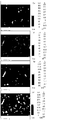
- Fig. 2 is a result of EPMA detection of the quenched alloy sheet of Example 3 of the first embodiment.
- Fig. 3 is a result of EPMA detection of the sintered magnet of Example 3 of the first embodiment.
- the BHH, magnetic performance evaluation process, and AGG measurement mentioned in each embodiment are defined as follows:
- BHH is the sum of (BH)max and Hcj and is one of the evaluation criteria for the comprehensive performance of the magnet.
- Magnetic performance evaluation process The sintered magnet was magnetically tested using the NIM ⁇ 10000H BH bulk rare earth permanent magnet non-destructive measurement system of China Metrology Institute.
- AGG measurement The sintered magnet was polished in a direction perpendicular to the orientation direction, and the AGG mentioned in the present invention was a crystal grain having a particle diameter exceeding 40 ⁇ m per the average AGG amount included in 1 cm 2 .
- the detection limit of FE-EPMA detection mentioned in each example is about 100 ppm, and the detection conditions are as follows:
- the maximum resolution of the FE ⁇ EPMA device is 3 nm, and the resolution can reach 50 nm under the above detection conditions.
- Raw material preparation process preparation of 99.5% purity Nd, Dy, industrial Fe-B, industrial pure Fe, purity 99.9% Co and purity 99.5% Cu, Al, purity 99.999% W, atomic percentage at% Formulated.
- the W content in selected Nd, Dy, Fe, B, Al, Cu, and Co is below the detection limit of the existing device, and the source of W is additionally added. W metal.
- Each serial number group was prepared according to the elemental composition in Table 2, and 100 kg of raw materials were weighed and prepared.
- Casting process Ar gas is introduced into the melting furnace after vacuum melting to bring the gas pressure to 50,000 Pa, and then cast by a single roll quenching method to obtain a quenched alloy at a cooling rate of 10 2 ° C / sec to 10 4 ° C / sec. The quenched alloy was heat treated at 600 ° C for 60 minutes and then cooled to room temperature.
- the Cu, Nd, and W components of the quenched alloy prepared in Example 3 were subjected to FE-EPMA (Field Emission Electron Probe Microanalysis) [JEOL, 8530F], and the results are shown in FIG. It can be observed that W is distributed in the R-rich phase with a higher dispersion.
- FE-EPMA Field Emission Electron Probe Microanalysis
- the FE-EPMA test was performed on the quenched alloy sheets of Examples 2, 3, 4, 5 and 6, and the W-rich region was uniformly dispersed in the crystal grain boundaries and accounted for at least 50% by volume of the grain boundaries of the alloy, wherein The W-rich region is a region having a W content of 0.004 at% or more and 0.26 at% or less.
- Hydrogen breaking pulverization process a hydrogen-breaking furnace in which a quenching alloy is placed is evacuated at room temperature, and then a hydrogen gas having a purity of 99.5% is introduced into a hydrogen-breaking furnace to a pressure of 0.1 MPa, and after standing for 2 hours, the temperature is raised while evacuating. The vacuum was evacuated at a temperature of 500 ° C, and then cooled, and the powder after the pulverization of hydrogen was taken out.
- the powder after the hydrogen pulverization was subjected to jet milling at a pressure of 0.4 MPa in a nitrogen gas atmosphere having an oxidizing gas content of 100 ppm or less to obtain a fine powder, and the average particle size of the fine powder was 4.5 ⁇ m.
- Oxidizing gas refers to oxygen or moisture.
- the finely pulverized fine powder (30% by weight based on the total weight of the fine powder) was classified by a classifier to remove particles having a particle diameter of 1.0 ⁇ m or less, and the classified fine powder was mixed with the remaining unfractionated fine powder.
- the volume of the powder having a particle diameter of 1.0 ⁇ m or less is reduced to 10% or less of the entire volume of the powder.
- Methyl octanoate was added to the powder after the jet mill pulverization, and the methyl octanoate was added in an amount of 0.2% by weight of the mixed powder, followed by thorough mixing with a V-type mixer.
- Magnetic field forming process Using a right-angle oriented magnetic field forming machine, the above-mentioned methyl octanoate-added powder was once formed into a cube having a side length of 25 mm in a 1.8 T orientation magnetic field at a molding pressure of 0.4 ton/cm 2 . After one forming, it demagnetizes in a magnetic field of 0.2T.
- Sintering process Each formed body is moved to a sintering furnace for sintering, and the sintering is maintained at a temperature of 200 ° C and 800 ° C for 2 hours under a vacuum of 10 -3 Pa, and then sintered at a temperature of 1030 ° C for 2 hours, and then passed through. After the Ar gas was introduced to bring the gas pressure to 0.1 MPa, it was cooled to room temperature.
- Heat treatment process The sintered body was heat-treated at a temperature of 460 ° C for 1 hour in high-purity Ar gas, and then cooled to room temperature and taken out.
- the heat-treated sintered body is processed into A magnet having a thickness of 5 mm has a direction of magnetic field orientation of 5 mm.
- the magnets of the sintered bodies of Examples 1 to 7 were directly subjected to magnetic property detection to evaluate their magnetic properties.
- the evaluation results of the examples of the magnets are shown in Tables 3 and 4:
- the amorphous phase and the isotropic phase in Table 3 are the amorphous phases and the isotropy in the quenched alloy. Sexual phase.
- the W-rich phase in Table 3 is a region of 0.004 at% or more and 0.26 at% or less.
- the W content in selected Nd, Pr, Tb, Fe, B, Al, and Cu is below the detection limit of the existing equipment, and the source of W is additionally added. W metal.
- Each serial number group was prepared according to the elemental composition in Table 5, and 100 kg of raw materials were weighed and prepared.
- Casting process Ar gas is introduced into a melting furnace after vacuum melting to bring the gas pressure to 30,000 Pa, and then casting is performed by a single roll quenching method, and a quenched alloy is obtained at a cooling rate of 10 2 ° C / sec to 10 4 ° C / sec. The quenched alloy was heat treated at 600 ° C for 60 minutes and then cooled to room temperature.
- the FE-EPMA was tested on the quenched alloy sheets of Examples 2 to 7.
- the W-rich region was uniformly dispersed in the crystal grain boundaries and accounted for at least 50% by volume of the alloy crystal grain boundaries, wherein the W-rich region was W content. It is an area of 0.004 at% or more and 0.26 at% or less.
- Hydrogen breaking and pulverizing process a hydrogen breaking furnace in which a quenching alloy is placed is evacuated at room temperature, and then a hydrogen gas having a purity of 99.5% is introduced into the hydrogen breaking furnace to a pressure of 0.1 MPa, and after standing for 125 minutes, the temperature is raised while vacuuming. The vacuum was evacuated at a temperature of 500 ° C for 2 hours, and then cooled, and the hydrogen-crushed powder was taken out.
- the pressure in the pulverizing chamber is The powder after the hydrogen pulverization was subjected to jet mill pulverization under a pressure of 0.41 MPa to obtain a fine powder, and the average particle size of the fine powder was 4.30 ⁇ m.
- Oxidizing gas refers to oxygen or moisture.
- Methyl octanoate was added to the powder after the jet mill pulverization, and the methyl octanoate was added in an amount of 0.25% by weight of the mixed powder, and then thoroughly mixed by a V-type mixer.
- Magnetic field forming process Using a right angle oriented type magnetic field forming machine, the above-mentioned methyl octanoate-added powder was once formed into a cube having a side length of 25 mm in a 1.8 T orientation magnetic field at a molding pressure of 0.3 ton/cm 2 . After one forming, it demagnetizes in a magnetic field of 0.2T.
- each formed body is moved to a sintering furnace for sintering, and the sintering is maintained at a temperature of 200 ° C and 800 ° C for 3 hours under a vacuum of 10 -3 Pa, and then sintered at a temperature of 1020 ° C for 2 hours. After the Ar gas was introduced to bring the gas pressure to 0.1 MPa, it was cooled to room temperature.
- Heat treatment process The sintered body was heat-treated at a temperature of 620 ° C for 1 hour in high-purity Ar gas, and then cooled to room temperature and taken out.
- the heat-treated sintered body is processed into A magnet having a thickness of 5 mm has a direction of magnetic field orientation of 5 mm.
- the magnets of the sintered bodies of Examples 1 to 8 were directly subjected to magnetic property measurement to evaluate their magnetic properties.
- the evaluation results of the examples of the magnets are shown in Tables 6 and 7:
- the amorphous phase and the isotropic phase in Table 6 are the amorphous phase and the isotropic phase in the quenched alloy.
- the W-rich phase in Table 6 is a region of 0.004 at% or more and 0.26 at% or less.
- FE-EPMA detection (JEOL, 8530F) was performed on Examples 2 to 7, and as a result of the detection, it was observed that W uniformly pinned the grain boundary with a high degree of dispersion. Migration to prevent the formation of AGG.
- the W content in the selected Nd, Fe, B, Cu, and Co raw materials is below the detection limit of the existing equipment, and the source of W is the additionally added W metal.
- the ingredients were weighed and prepared, and 700 Kg of raw materials were prepared.
- Smelting process The prepared raw materials are placed in a crucible made of alumina, and vacuum-melted at a temperature of 1500 ° C or lower in a vacuum of 10 ⁇ 2 Pa in a high-frequency vacuum induction melting furnace.
- Casting process Ar gas is introduced into the melting furnace after vacuum melting to bring the gas pressure to 50,000 Pa, and then cast by a single roll quenching method to obtain a quenched alloy at a cooling rate of 10 2 ° C / sec to 10 4 ° C / sec. The quenched alloy was heat treated at 600 ° C for 60 minutes and then cooled to room temperature.
- the FE-EPMA test is performed on the quenched alloy sheet.
- the W-rich region has a uniform dispersion distribution in the crystal grain boundary and accounts for at least 50% by volume of the crystal grain boundary of the alloy.
- the W-rich region has a W content of 0.004 at% or more. Area below 0.26at%.
- Hydrogen breaking and pulverizing process the hydrogen quenching furnace in which the quenching alloy is placed is evacuated at room temperature, and then hydrogen gas having a purity of 99.5% is introduced into the hydrogen breaking furnace to a pressure of 0.1 MPa, and after standing for 97 minutes, the temperature is raised while vacuuming. The vacuum was evacuated at a temperature of 500 ° C for 2 hours, and then cooled, and the hydrogen-crushed powder was taken out.
- the powder after the hydrogen pulverization is divided into 7 parts, and each of the powders is pulverized under the pressure of the pulverization chamber at a pressure of 0.42 MPa in an atmosphere having an oxidizing gas content of 10 to 3,000 ppm or less.
- the powder was subjected to jet mill pulverization to obtain a fine powder having an average particle size of 4.51 ⁇ m.
- Oxidizing gas refers to oxygen or moisture.
- Methyl octanoate was added to each of the powders pulverized by the jet mill, and the amount of methyl octanoate added was 0.1% by weight of the powder after mixing, and then thoroughly mixed by a V-type mixer.
- Magnetic field forming process The above-mentioned powder added with methyl octanoate was formed into a side length of 25 mm at a molding pressure of 0.2 ton/cm 2 in a 1.8 T oriented magnetic field using a magnetic field forming machine of a right angle orientation type. The cube is demagnetized in a magnetic field of 0.2 T after one forming.
- each formed body is moved to a sintering furnace for sintering, and the sintering is maintained at a temperature of 200 ° C and 700 ° C for 2 hours under a vacuum of 10 -3 Pa, and then sintered at a temperature of 1020 ° C for 2 hours, and then passed through.
- the Ar gas was introduced to bring the gas pressure to 0.1 MPa, it was cooled to room temperature.
- Heat treatment process The sintered body is subjected to a primary heat treatment at 900 ° C for 1 hour in a high-purity Ar gas, and then subjected to a secondary heat treatment at a temperature of 500 ° C for 1 hour, and after cooling to room temperature, it is taken out.
- the heat-treated sintered body is processed into A magnet having a thickness of 5 mm has a direction of magnetic field orientation of 5 mm.
- the sintered magnet was placed in a 150 ° C environment for 30 min, then cooled naturally to room temperature, and the magnetic flux was measured. The measured results were compared with the measured data before heating to calculate the flux decay before and after heating. rate.
- the W-rich phase in Table 9 is a region of 0.004 at% or more and 0.26 at% or less.
- FE-EPMA detection (JEOL, 8530F) was performed on Examples 2 to 6, and as a result of the detection, it was also observed that W was uniformly pinned with a high degree of dispersion. The migration of the boundary prevents the formation of AGG.
- Raw material preparation process preparation of 99.5% purity Nd, Dy, industrial Fe-B, industrial pure Fe, purity 99.9% Co and purity 99.5% Cu, Al, purity 99.999% W, atomic percentage at% Formulated.
- the W content in the selected Nd, Dy, B, Al, Cu, Co, and Fe is below the detection limit of the existing device, and the source of W is additionally added.
- W metal. Its content is shown in Table 11:
- Each serial number group was prepared according to the elemental composition in Table 11, and 100 kg of raw materials were weighed and prepared.
- Casting process Ar gas is introduced into the melting furnace after vacuum melting to bring the gas pressure to 20,000 Pa, and then cast by a single roll quenching method to obtain a quenched alloy at a cooling rate of 10 2 ° C / sec to 10 4 ° C / sec. The quenched alloy was subjected to heat treatment at 800 ° C for 10 minutes, and then cooled to room temperature.
- the FE-EPMA was tested on the quenched alloy sheets of Examples 1 to 7, and the W-rich region was uniformly dispersed in the crystal grain boundaries and accounted for at least 50% by volume of the alloy crystal grain boundaries, wherein the W-rich region was W content. It is an area of 0.004 at% or more and 0.26 at% or less.
- Hydrogen breaking and pulverizing process the hydrogen quenching furnace in which the quenching alloy is placed is evacuated at room temperature, and then hydrogen gas having a purity of 99.5% is introduced into the hydrogen breaking furnace to a pressure of 0.1 MPa, and after being left for 120 minutes, the temperature is raised while vacuuming. The vacuum was evacuated at a temperature of 500 ° C for 2 hours, and then cooled, and the hydrogen-crushed powder was taken out.
- the powder after the hydrogen pulverization is subjected to jet milling at a pressure of a pulverization chamber pressure of 0.6 MPa in an atmosphere having an oxidizing gas content of 100 ppm or less to obtain a fine powder, and the average particle size of the fine powder is 4.5 ⁇ m.
- Oxidizing gas refers to oxygen or moisture.
- the finely pulverized fine powder (30% by weight based on the total weight of the fine powder) was classified by a classifier to remove the particles having a particle diameter of 1.0 ⁇ m or less, and the classified fine powder was mixed with the remaining unfractionated fine powder. After mixing In the fine powder, the volume of the powder having a particle diameter of 1.0 ⁇ m or less is reduced to 2% or less of the entire volume of the powder.
- Methyl octanoate was added to the powder after the jet mill pulverization, and the methyl octanoate was added in an amount of 0.2% by weight of the mixed powder, followed by thorough mixing with a V-type mixer.
- Magnetic field forming process Using a right-angle oriented magnetic field forming machine, the above-mentioned methyl octanoate-added powder was once formed into a cube having a side length of 25 mm in a 1.8 T orientation magnetic field at a molding pressure of 0.2 ton/cm 2 . After one forming, it demagnetizes in a magnetic field of 0.2T.
- each formed body is moved to a sintering furnace for sintering, and the sintering is maintained at a temperature of 200 ° C and 800 ° C for 2 hours under a vacuum of 10 -3 Pa, and then sintered at a temperature of 1040 ° C for 2 hours, followed by After the Ar gas was introduced to bring the gas pressure to 0.1 MPa, it was cooled to room temperature.
- Heat treatment process The sintered body was heat-treated at a temperature of 400 ° C for 1 hour in high-purity Ar gas, and then cooled to room temperature and taken out.
- the heat-treated sintered body is processed into A magnet having a thickness of 5 mm has a direction of magnetic field orientation of 5 mm.
- the magnets of the sintered bodies of Examples 1 to 7 were directly subjected to magnetic property detection to evaluate their magnetic properties.
- the evaluation results of the examples of the magnets are shown in Table 12 and Table 13:
- the amorphous phase and the isotropic phase in Table 12 are the amorphous phase and the isotropic phase in the quenched alloy.
- the W-rich phase in Table 12 is a region of 0.004 at% or more and 0.26 at% or less.
- Raw material preparation process preparation of 99.5% purity Nd, Dy, industrial Fe-B, industrial pure Fe, purity 99.9% Co and purity 99.5% Cu, Al, purity 99.999% W, atomic percentage at% Formulated.
- the W content in the selected Nd, Dy, B, Al, Cu, Co, and Fe is below the detection limit of the existing device, and the source of W is additionally added.
- W metal. The content of each element is shown in Table 14:
- Each serial number group was prepared according to the elemental composition in Table 14, and 100 kg of raw materials were weighed and prepared.
- Casting process Ar gas is introduced into the melting furnace after vacuum melting to bring the gas pressure to 50,000 Pa, and then cast by a single roll quenching method to obtain a quenched alloy at a cooling rate of 10 2 ° C / sec to 10 4 ° C / sec. The quenched alloy was heat treated at 700 ° C for 5 minutes and then cooled to room temperature.
- Hydrogen breaking and pulverizing process the hydrogen quenching furnace in which the quenching alloy is placed is evacuated at room temperature, and then hydrogen gas having a purity of 99.5% is introduced into the hydrogen breaking furnace to a pressure of 0.1 MPa, and after being left for 120 minutes, the temperature is raised while vacuuming. The vacuum was evacuated at a temperature of 600 ° C for 2 hours, and then cooled, and the powder after the pulverization of hydrogen was taken out.
- the powder after the hydrogen pulverization is subjected to jet milling at a pressure of a pulverization chamber pressure of 0.5 MPa in an atmosphere having an oxidizing gas content of 100 ppm or less to obtain a fine powder, and the average particle size of the fine powder is 5.0 ⁇ m.
- Oxidizing gas refers to oxygen or moisture.
- the finely pulverized fine powder (30% by weight based on the total weight of the fine powder) was sieved to remove the particles having a particle diameter of 1.0 ⁇ m or less, and the fine powder after the sieving was mixed with the remaining unsifted fine powder.
- the volume of the powder having a particle diameter of 1.0 ⁇ m or less is reduced to 10% or less of the entire volume of the powder.
- Methyl octanoate was added to the powder after the jet mill pulverization, and the methyl octanoate was added in an amount of 0.2% by weight of the mixed powder, followed by thorough mixing with a V-type mixer.
- Magnetic field forming process Using a right-angle oriented magnetic field forming machine, the above-mentioned methyl octanoate-added powder was once formed into a cube having a side length of 25 mm in a 1.8 T orientation magnetic field at a molding pressure of 0.2 ton/cm 2 . After one forming, it demagnetizes in a magnetic field of 0.2T.
- each formed body is moved to a sintering furnace for sintering, and the sintering is maintained at a temperature of 200 ° C and 800 ° C for 2 hours under a vacuum of 10 -3 Pa, and then sintered at a temperature of 1060 ° C for 2 hours, and then passed through. After the Ar gas was introduced to bring the gas pressure to 0.1 MPa, it was cooled to room temperature.
- Heat treatment process The sintered body was heat-treated at a temperature of 420 ° C for 1 hour in high-purity Ar gas, and then cooled to room temperature and taken out.
- the heat-treated sintered body is processed into A magnet having a thickness of 5 mm has a direction of magnetic field orientation of 5 mm.
- the magnets of the sintered bodies of Examples 1 to 7 were directly subjected to magnetic property detection to evaluate their magnetic properties.
- the evaluation results of the examples of the magnets are shown in Table 15:
- the amorphous phase and the isotropic phase in Table 15 are the amorphous phase and the isotropic phase in the quenched alloy.
- the W-rich phase in Table 15 is a region of 0.004 at% or more and 0.26 at% or less.
- Each group of sintered bodies obtained in Example 1 was separately processed into A magnet having a thickness of 5 mm has a direction of magnetic field orientation of 5 mm.
- Grain boundary diffusion treatment process the magnets processed by each group of sintered bodies are washed, and after the surface is cleaned, the raw materials prepared by using Dy oxide and Tb fluoride in a ratio of 3:1 are sprayed on the magnets in a comprehensive manner.
- the coated magnet was dried and heat-dissipated at a temperature of 850 ° C for 24 hours in a high-purity Ar gas atmosphere.
- the trace W in the present invention produces very minute W crystals in the crystal grain boundaries and does not inhibit the diffusion of Dy and Tb, so the diffusion speed is very fast. Further, since an appropriate amount of Cu is contained, an Nd-rich phase having a low melting point is formed, and an effect of further promoting diffusion can be exhibited. Therefore, the magnet of the present invention can achieve very high performance by diffusion of grain boundaries of Dy and Tb.
- Nd, Dy, Tb having a purity of 99.9%, B having a purity of 99.9%, Fe having a purity of 99.9%, and Cu, Co, Nb, Al, and Ga having a purity of 99.5% are prepared at an atomic percentage at%.
- the W content in selected Dy, Tb, Fe, B, Cu, Co, Nb, Al, and Ga is below the detection limit of the existing equipment, and the selected one is used.
- Nd contains W, and the content of W element is 0.01 at%.
- Each serial number group was prepared according to the elemental composition in Table 18, and 100 kg of raw materials were weighed and prepared.
- Casting process Ar gas is introduced into the melting furnace after vacuum melting to bring the gas pressure to 35,000 Pa, and then casting is performed by a single roll quenching method, and a quenched alloy is obtained at a cooling rate of 10 2 ° C / sec to 10 4 ° C / sec. The quenched alloy was heat treated at 550 ° C for 10 minutes and then cooled to room temperature.
- Hydrogen breaking and pulverizing process the hydrogen-dissolving furnace in which the quenching alloy is placed is evacuated at room temperature, and then hydrogen gas having a purity of 99.5% is introduced into the hydrogen breaking furnace to a pressure of 0.085 MPa, and after standing for 160 minutes, the temperature is raised while vacuuming. The vacuum was applied at a temperature of 520 ° C, and then cooled, and hydrogen was taken out to break the pulverized powder.
- the powder after the hydrogen pulverization was subjected to jet milling at a pressure of 0.42 MPa in an atmosphere having an oxidizing gas content of 10 ppm or less to obtain a fine powder, and the average particle size of the fine powder was 4.28 ⁇ m.
- Oxidizing gas refers to oxygen or moisture.
- Methyl octanoate was added to the powder after the jet mill pulverization, and the methyl octanoate was added in an amount of 0.25% by weight of the mixed powder, and then thoroughly mixed by a V-type mixer.
- Magnetic field forming process Using a right angle oriented type magnetic field forming machine, the above-mentioned methyl octanoate-added powder was once formed into a cube having a side length of 25 mm in a 1.8 T orientation magnetic field at a molding pressure of 0.3 ton/cm 2 . After one forming, it demagnetizes in a magnetic field of 0.2T.
- each formed body is moved to a sintering furnace for sintering, and the sintering is maintained at a temperature of 300 ° C and 800 ° C for 3 hours under a vacuum of 10 -3 Pa, and then sintered at a temperature of 1030 ° C for 2 hours, and then passed through. After the Ar gas was introduced to bring the gas pressure to 0.1 MPa, it was cooled to room temperature.
- Heat treatment process The sintered body was heat-treated at 600 ° C for 2 hours in high-purity Ar gas, and then cooled to room temperature and taken out.
- the heat-treated sintered body is processed into A magnet having a thickness of 5 mm has a direction of magnetic field orientation of 5 mm.
- the magnets of the sintered bodies of Examples 1 to 8 were directly subjected to magnetic property measurement to evaluate their magnetic properties.
- the evaluation results of the examples of the magnets are shown in Tables 19 and 20:
- the amorphous phase and the isotropic phase in Table 19 are the amorphous phase and the isotropic phase in the quenched alloy.
- the W-rich phase in Table 19 is a region of 0.004 at% or more and 0.26 at% or less.
- O, C and N which will be the above O, C and N.
- the content of each element in the magnet is controlled to be 0.1 to 0.5 at%, 0.4 at% or less, and 0.2 at% or less.
- FE-EPMA detection (JEOL, 8530F) was performed on Examples 1 to 8, and as a result of the detection, it was observed that W uniformly pinned the grain boundary with a high degree of dispersion. Migration to prevent the formation of AGG.
- the W content in selected Dy, Gd, Tb, Fe, B, Cu, Co, Nb, Al, and Ga is below the detection limit of the existing equipment.
- the selected Nd contains W and the content of W element is 0.01 at%.
- Each serial number group was prepared according to the elemental composition in Table 21, and 100 kg of raw materials were weighed and prepared.
- Casting process Ar gas is introduced into the melting furnace after vacuum melting to bring the gas pressure to 45,000 Pa, and then casting is performed by a single roll quenching method, and a quenched alloy is obtained at a cooling rate of 10 2 ° C / sec to 10 4 ° C / sec. The quenched alloy was heat treated at 800 ° C for 5 minutes and then cooled to room temperature.
- Hydrogen breaking and pulverizing process a hydrogen breaking furnace in which a quenching alloy is placed is evacuated at room temperature, and then a hydrogen gas having a purity of 99.5% is introduced into a hydrogen breaking furnace to a pressure of 0.09 MPa, and after standing for 150 minutes, the temperature is raised while vacuuming. The vacuum was evacuated at a temperature of 600 ° C, and then cooled, and the pulverized powder was taken out by hydrogen.
- the powder after the hydrogen pulverization is subjected to jet milling at a pressure of 0.5 MPa in an atmosphere having an oxidizing gas content of 30 ppm or less to obtain a fine powder, and the average particle size of the fine powder is 4.1 ⁇ m.
- Oxidizing gas refers to oxygen or moisture.
- the aluminum stearate was added to the powder after the jet mill pulverization, and the amount of the aluminum stearate added was 0.05% by weight of the mixed powder, followed by thorough mixing with a V-type mixer.
- Magnetic field forming process The above-mentioned aluminum stearate-added powder was once formed into a side length of 25 mm in a 1.8 T orientation magnetic field at a molding pressure of 0.3 ton/cm 2 using a right angle orientation type magnetic field molding machine. The cube is demagnetized in a magnetic field of 0.2 T after one forming.
- each formed body is moved to a sintering furnace for sintering, and the sintering is maintained at a temperature of 200 ° C and 800 ° C for 3 hours under a vacuum of 10 -3 Pa, and then sintered at a temperature of 1050 ° C for 2 hours, and then passed through. After the Ar gas was introduced to bring the gas pressure to 0.1 MPa, it was cooled to room temperature.
- Heat treatment process The sintered body was heat-treated at a temperature of 480 ° C for 2 hours in high-purity Ar gas, and then cooled to room temperature and taken out.
- the heat-treated sintered body is processed into A magnet having a thickness of 5 mm has a direction of magnetic field orientation of 5 mm.
- the magnets of the sintered bodies of Examples 1 to 5 were directly subjected to magnetic property measurement to evaluate their magnetic properties.
- the evaluation results of the examples of the magnets are shown in Table 22 and Table 23:
- the amorphous phase and the isotropic phase in Table 23 are the amorphous phase and the isotropic phase in the quenched alloy.
- the W-rich phase in Table 23 is a region of 0.004 at% or more and 0.26 at% or less.
- the applicant has learned through experiments that the content of Zr should also be controlled to be 0.2 at% or less.
- FE-EPMA detection (JEOL, 8530F) was performed on Examples 1 to 5, and as a result of the detection, it was observed that W uniformly pinned the grain boundary with a high degree of dispersion. Migration to prevent the formation of AGG.
Landscapes
- Chemical & Material Sciences (AREA)
- Engineering & Computer Science (AREA)
- Materials Engineering (AREA)
- Mechanical Engineering (AREA)
- Metallurgy (AREA)
- Organic Chemistry (AREA)
- Power Engineering (AREA)
- Crystallography & Structural Chemistry (AREA)
- Inorganic Chemistry (AREA)
- Hard Magnetic Materials (AREA)
- Manufacture Of Metal Powder And Suspensions Thereof (AREA)
- Powder Metallurgy (AREA)
Abstract
Description


Claims (12)
- 一种含W的R‐Fe‐B‐Cu系烧结磁铁,所述烧结磁铁含有R2Fe14B型主相,所述的R为包括Nd或Pr的至少一种稀土元素,其特征在于,所述稀土磁铁的结晶晶界中具有W含量为0.004at%以上、0.26at%以下的富W区域,所述富W区域在所述结晶晶界中呈均一分散的分布,并占所述烧结磁铁的5.0体积%~11.0体积%。
- 根据权利要求1中所述的一种含W的R‐Fe‐B‐Cu系烧结磁铁,其特征在于,所述磁铁由包括如下成分的原料制成:R:12at%~15.2at%,B:5at%~8at%,W:0.0005at%~0.03at%,Cu:0.05at%~1.2at%,X:5.0at%以下、X为选自Al、Si、Ga、Sn、Ge、Ag、Au、Bi、Mn、Nb、Zr或Cr中的至少1种元素,在X包括Nb和/或Zr之时,Nb和Zr的总含量在0.20at%以下,余量为0at%~20at%的Co、Fe、以及不可避免的杂质,所述杂质包括O,且所述烧结磁铁的O含量为0.1at%~1.0at%。
- 根据权利要求2中所述的一种含W的R‐Fe‐B‐Cu系烧结磁铁,其特征在于:X的含量在2.0at%以下。
- 根据权利要求3中所述的一种含W的R‐Fe‐B‐Cu系烧结磁铁,其特征在于,由如下的步骤制得:将烧结磁铁原料成分熔融液以102℃/秒~104℃/秒的冷却速度制备成烧结磁铁用合金的工序;将烧结磁铁用合金粗粉碎后再通过微粉碎制成细粉的工序;用磁场成形法获得成形体,并在真空或惰性气体中以900℃~1100℃的温度对所述成形体进行烧结后获得。
- 根据权利要求1或2或3或4中所述的一种含W的R‐Fe‐B‐Cu系烧结磁铁,其特征在于:所述烧结磁铁的B含量优选为5at%~6.5at%。
- 根据权利要求1或2或3或4中所述的一种含W的R‐Fe‐B‐Cu系烧结磁铁,其特征在于:所述烧结磁铁的Al含量优选为0.8at%~2.0at%。
- 根据权利要求4所述的一种含W的R‐Fe‐B‐Cu系烧结磁铁,其特征在于:所述粗粉碎为烧结磁铁用合金吸氢破碎、得到粗粉的工序,所述微粉碎为粗粉气流粉碎的工序,还包括从微粉碎后的粉末中除去粒径1.0μm以下的至少一部分,由此使粒径1.0μm以下的粉末体积减少至全体粉末体积的10%以下的工序。
- 根据权利要求1或2或3或4中所述的一种含W的R‐Fe‐B‐Cu系烧结磁铁,其特征在于:还包括将所述烧结磁体进行RH晶界扩散处理的工序,所述的RH选自Dy或Tb中的至少一种。
- 根据权利要求8中所述的一种含W的R‐Fe‐B‐Cu系烧结磁铁,其特征在于,还包括时效处理的步骤:对所述烧结磁铁在400℃~650℃的温度进行时效处理。
- 根据权利要求1或2或3或4中所述的一种含W的R‐Fe‐B‐Cu系烧结磁铁,其特征在于:所述烧结磁铁的O含量为0.1at%~0.5at%。
- 根据权利要求1或2或3或4中所述的一种含W的R‐Fe‐B‐Cu系烧结磁铁,其特征在于:所述烧结磁铁的Ga含量为0.05at%~0.8at%。
- 一种含W的R‐Fe‐B‐Cu系烧结磁铁用急冷合金,其特征在于:所述急冷合金的结晶晶界中具有W含量为0.004at%以上、0.26at%以下的富W区域,所述富W区域在所述结晶晶界中呈均一分散的分布,并占所述结晶晶界的至少50体积%。
Priority Applications (8)
| Application Number | Priority Date | Filing Date | Title |
|---|---|---|---|
| DK15772705.8T DK3128521T3 (da) | 2014-03-31 | 2015-03-31 | W-indeholdende R-Fe-B-Cu sintret magnet og bratkølet legering |
| ES15772705T ES2742188T3 (es) | 2014-03-31 | 2015-03-31 | Imán sinterizado de R-Fe-B-Cu que contiene W y aleación de temple |
| JP2016560501A JP6528046B2 (ja) | 2014-03-31 | 2015-03-31 | W含有R−Fe−B−Cu系焼結磁石及び急冷合金 |
| EP15772705.8A EP3128521B8 (en) | 2014-03-31 | 2015-03-31 | W-containing r-fe-b-cu sintered magnet and quenching alloy |
| CN201580002027.7A CN105659336B (zh) | 2014-03-31 | 2015-03-31 | 一种含W的R‑Fe‑B‑Cu系烧结磁铁及急冷合金 |
| BR112016013421A BR112016013421B8 (pt) | 2014-03-31 | 2015-03-31 | Ímã sinterizado de r-fe-b-cu contendo w e sua liga de têmpera |
| US15/185,430 US10381139B2 (en) | 2014-03-31 | 2016-06-17 | W-containing R—Fe—B—Cu sintered magnet and quenching alloy |
| US16/410,090 US10614938B2 (en) | 2014-03-31 | 2019-05-13 | W-containing R—Fe—B—Cu sintered magnet and quenching alloy |
Applications Claiming Priority (2)
| Application Number | Priority Date | Filing Date | Title |
|---|---|---|---|
| CN201410126926.5A CN104952574A (zh) | 2014-03-31 | 2014-03-31 | 一种含W的Nd-Fe-B-Cu系烧结磁铁 |
| CN201410126926.5 | 2014-03-31 |
Related Child Applications (1)
| Application Number | Title | Priority Date | Filing Date |
|---|---|---|---|
| US15/185,430 Continuation US10381139B2 (en) | 2014-03-31 | 2016-06-17 | W-containing R—Fe—B—Cu sintered magnet and quenching alloy |
Publications (1)
| Publication Number | Publication Date |
|---|---|
| WO2015149685A1 true WO2015149685A1 (zh) | 2015-10-08 |
Family
ID=54167172
Family Applications (1)
| Application Number | Title | Priority Date | Filing Date |
|---|---|---|---|
| PCT/CN2015/075512 Ceased WO2015149685A1 (zh) | 2014-03-31 | 2015-03-31 | 一种含W的R‐Fe‐B‐Cu系烧结磁铁及急冷合金 |
Country Status (8)
| Country | Link |
|---|---|
| US (1) | US10381139B2 (zh) |
| EP (1) | EP3128521B8 (zh) |
| JP (1) | JP6528046B2 (zh) |
| CN (2) | CN104952574A (zh) |
| BR (1) | BR112016013421B8 (zh) |
| DK (1) | DK3128521T3 (zh) |
| ES (1) | ES2742188T3 (zh) |
| WO (1) | WO2015149685A1 (zh) |
Cited By (3)
| Publication number | Priority date | Publication date | Assignee | Title |
|---|---|---|---|---|
| CN110976887A (zh) * | 2019-12-17 | 2020-04-10 | 哈尔滨东大高新材料股份有限公司 | AgWC(T)/CuC(X)触头材料及其制备方法 |
| US10971289B2 (en) * | 2015-09-28 | 2021-04-06 | Xiamen Tungsten Co., Ltd. | Composite R-Fe-B series rare earth sintered magnet comprising Pr and W |
| CN119601332A (zh) * | 2024-11-27 | 2025-03-11 | 江西理工大学 | 一种多合金高综合性能磁体及其制备方法 |
Families Citing this family (9)
| Publication number | Priority date | Publication date | Assignee | Title |
|---|---|---|---|---|
| US10614938B2 (en) * | 2014-03-31 | 2020-04-07 | Xiamen Tungsten Co., Ltd. | W-containing R—Fe—B—Cu sintered magnet and quenching alloy |
| TWI673729B (zh) * | 2015-03-31 | 2019-10-01 | 日商信越化學工業股份有限公司 | R-Fe-B系燒結磁石及其製造方法 |
| US10468168B2 (en) * | 2015-04-02 | 2019-11-05 | Xiamen Tungsten Co., Ltd. | Rare-earth magnet comprising holmium and tungsten |
| JP6645219B2 (ja) * | 2016-02-01 | 2020-02-14 | Tdk株式会社 | R−t−b系焼結磁石用合金、及びr−t−b系焼結磁石 |
| JP6724865B2 (ja) | 2016-06-20 | 2020-07-15 | 信越化学工業株式会社 | R−Fe−B系焼結磁石及びその製造方法 |
| JP6614084B2 (ja) | 2016-09-26 | 2019-12-04 | 信越化学工業株式会社 | R−Fe−B系焼結磁石の製造方法 |
| CN110021466A (zh) * | 2017-12-28 | 2019-07-16 | 厦门钨业股份有限公司 | 一种R-Fe-B-Cu-Al系烧结磁铁及其制备方法 |
| CN109192426B (zh) * | 2018-09-05 | 2020-03-10 | 福建省长汀金龙稀土有限公司 | 含有Tb和Hf的R-Fe-B系烧结磁体及其制备方法 |
| CN110993233B (zh) * | 2019-12-09 | 2021-08-27 | 厦门钨业股份有限公司 | 一种r-t-b系永磁材料、原料组合物、制备方法、应用 |
Citations (2)
| Publication number | Priority date | Publication date | Assignee | Title |
|---|---|---|---|---|
| CN101320609A (zh) * | 2008-03-21 | 2008-12-10 | 浙江大学 | 晶界相重构的高耐蚀性烧结钕铁硼磁体及其制备方法 |
| CN102511071A (zh) * | 2010-03-31 | 2012-06-20 | 日东电工株式会社 | 永久磁铁及永久磁铁的制造方法 |
Family Cites Families (39)
| Publication number | Priority date | Publication date | Assignee | Title |
|---|---|---|---|---|
| DE3783975T2 (de) * | 1986-07-23 | 1993-05-27 | Hitachi Metals Ltd | Dauermagnet mit guter thermischer stabilitaet. |
| US5223047A (en) * | 1986-07-23 | 1993-06-29 | Hitachi Metals, Ltd. | Permanent magnet with good thermal stability |
| JPH01103805A (ja) * | 1987-07-30 | 1989-04-20 | Tdk Corp | 永久磁石 |
| JP2720040B2 (ja) | 1988-02-26 | 1998-02-25 | 住友特殊金属株式会社 | 焼結永久磁石材料とその製造方法 |
| JP3932143B2 (ja) | 1992-02-21 | 2007-06-20 | Tdk株式会社 | 磁石の製造方法 |
| JP2746818B2 (ja) | 1993-06-02 | 1998-05-06 | 信越化学工業株式会社 | 希土類焼結永久磁石の製造方法 |
| JPH0745412A (ja) | 1993-07-28 | 1995-02-14 | Sumitomo Special Metals Co Ltd | R−Fe−B系永久磁石材料 |
| DE69716588T2 (de) | 1996-04-10 | 2003-06-12 | Showa Denko K.K., Tokio/Tokyo | Gusslegierung für die Herstellung von Dauermagneten mit seltenen Erden und Verfahren zur Herstellung dieser Legierung und dieser Dauermagneten |
| EP1011113B1 (en) | 1998-12-11 | 2008-05-28 | Shin-Etsu Chemical Co., Ltd. | Method for the preparation of a rare earth permanent magnet |
| JP3712581B2 (ja) | 1999-02-15 | 2005-11-02 | 信越化学工業株式会社 | 永久磁石用合金薄帯および焼結永久磁石 |
| DE19945942C2 (de) | 1999-09-24 | 2003-07-17 | Vacuumschmelze Gmbh | Verfahren zur Herstellung von Dauermagneten aus einer borarmen Nd-Fe-B-Legierung |
| EP1164599B1 (en) | 2000-06-13 | 2007-12-05 | Shin-Etsu Chemical Co., Ltd. | R-Fe-B base permanent magnet materials |
| JP4371188B2 (ja) | 2000-08-22 | 2009-11-25 | 信越化学工業株式会社 | 高比電気抵抗性希土類磁石及びその製造方法 |
| CN1220220C (zh) | 2001-09-24 | 2005-09-21 | 北京有色金属研究总院 | 钕铁硼合金快冷厚带及其制造方法 |
| US20050098239A1 (en) | 2003-10-15 | 2005-05-12 | Neomax Co., Ltd. | R-T-B based permanent magnet material alloy and R-T-B based permanent magnet |
| US20070089806A1 (en) | 2005-10-21 | 2007-04-26 | Rolf Blank | Powders for rare earth magnets, rare earth magnets and methods for manufacturing the same |
| JP2007136543A (ja) * | 2005-11-17 | 2007-06-07 | Yoichi Hirose | 冷却装置及びストリップキャスティング装置並びにネオジウム系焼結磁石用合金鋳造薄片の冷却方法 |
| US7955443B2 (en) * | 2006-04-14 | 2011-06-07 | Shin-Etsu Chemical Co., Ltd. | Method for preparing rare earth permanent magnet material |
| KR101036968B1 (ko) | 2007-02-05 | 2011-05-25 | 쇼와 덴코 가부시키가이샤 | R-t-b계 합금 및 그 제조 방법, r-t-b계 희토류 영구자석용 미분말 및 r-t-b계 희토류 영구 자석 |
| JP5274781B2 (ja) | 2007-03-22 | 2013-08-28 | 昭和電工株式会社 | R−t−b系合金及びr−t−b系合金の製造方法、r−t−b系希土類永久磁石用微粉、r−t−b系希土類永久磁石 |
| CN101256859B (zh) | 2007-04-16 | 2011-01-26 | 有研稀土新材料股份有限公司 | 一种稀土合金铸片及其制备方法 |
| JP5153643B2 (ja) | 2007-06-29 | 2013-02-27 | Tdk株式会社 | 希土類磁石 |
| CN101981634B (zh) * | 2008-03-31 | 2013-06-12 | 日立金属株式会社 | R-t-b系烧结磁体及其制造方法 |
| CN101325109B (zh) | 2008-04-08 | 2010-09-08 | 浙江大学 | 晶界相重构的高强韧性烧结钕铁硼磁体及其制备方法 |
| EP2302646B1 (en) * | 2008-06-13 | 2018-10-31 | Hitachi Metals, Ltd. | R-t-cu-mn-b type sintered magnet |
| JP5303738B2 (ja) | 2010-07-27 | 2013-10-02 | Tdk株式会社 | 希土類焼結磁石 |
| JP5572673B2 (ja) | 2011-07-08 | 2014-08-13 | 昭和電工株式会社 | R−t−b系希土類焼結磁石用合金、r−t−b系希土類焼結磁石用合金の製造方法、r−t−b系希土類焼結磁石用合金材料、r−t−b系希土類焼結磁石、r−t−b系希土類焼結磁石の製造方法およびモーター |
| US9865382B2 (en) | 2011-08-03 | 2018-01-09 | Santoku Corporation | Alloy flakes as starting material for rare earth sintered magnet and method for producing same |
| JP6089535B2 (ja) * | 2011-10-28 | 2017-03-08 | Tdk株式会社 | R−t−b系焼結磁石 |
| CN104137198B (zh) | 2012-02-13 | 2016-05-04 | Tdk株式会社 | R-t-b系烧结磁体 |
| JP2013219322A (ja) * | 2012-03-12 | 2013-10-24 | Nitto Denko Corp | 希土類永久磁石及び希土類永久磁石の製造方法 |
| PH12013000103B1 (en) | 2012-04-11 | 2015-09-07 | Shinetsu Chemical Co | Rare earth sintered magnet and making method |
| JP6201446B2 (ja) * | 2012-06-22 | 2017-09-27 | Tdk株式会社 | 焼結磁石 |
| CN102956337B (zh) | 2012-11-09 | 2016-05-25 | 厦门钨业股份有限公司 | 一种烧结Nd-Fe-B系磁铁的省却工序的制作方法 |
| JP6202722B2 (ja) | 2012-12-06 | 2017-09-27 | 昭和電工株式会社 | R−t−b系希土類焼結磁石、r−t−b系希土類焼結磁石の製造方法 |
| CN103903823B (zh) | 2012-12-26 | 2016-12-28 | 宁波金鸡强磁股份有限公司 | 一种稀土永磁材料及其制备方法 |
| CN103050267B (zh) | 2012-12-31 | 2016-01-20 | 厦门钨业股份有限公司 | 一种基于细粉热处理的烧结Nd-Fe-B系磁铁制作方法 |
| CN103123839B (zh) | 2013-01-30 | 2015-04-22 | 浙江大学 | 一种应用高丰度稀土Ce生产的稀土永磁体及其制备方法 |
| CN105453194B (zh) | 2013-08-12 | 2018-10-16 | 日立金属株式会社 | R-t-b系烧结磁体 |
-
2014
- 2014-03-31 CN CN201410126926.5A patent/CN104952574A/zh active Pending
-
2015
- 2015-03-31 WO PCT/CN2015/075512 patent/WO2015149685A1/zh not_active Ceased
- 2015-03-31 BR BR112016013421A patent/BR112016013421B8/pt active IP Right Grant
- 2015-03-31 ES ES15772705T patent/ES2742188T3/es active Active
- 2015-03-31 DK DK15772705.8T patent/DK3128521T3/da active
- 2015-03-31 CN CN201580002027.7A patent/CN105659336B/zh active Active
- 2015-03-31 EP EP15772705.8A patent/EP3128521B8/en active Active
- 2015-03-31 JP JP2016560501A patent/JP6528046B2/ja active Active
-
2016
- 2016-06-17 US US15/185,430 patent/US10381139B2/en active Active
Patent Citations (2)
| Publication number | Priority date | Publication date | Assignee | Title |
|---|---|---|---|---|
| CN101320609A (zh) * | 2008-03-21 | 2008-12-10 | 浙江大学 | 晶界相重构的高耐蚀性烧结钕铁硼磁体及其制备方法 |
| CN102511071A (zh) * | 2010-03-31 | 2012-06-20 | 日东电工株式会社 | 永久磁铁及永久磁铁的制造方法 |
Non-Patent Citations (1)
| Title |
|---|
| See also references of EP3128521A4 * |
Cited By (3)
| Publication number | Priority date | Publication date | Assignee | Title |
|---|---|---|---|---|
| US10971289B2 (en) * | 2015-09-28 | 2021-04-06 | Xiamen Tungsten Co., Ltd. | Composite R-Fe-B series rare earth sintered magnet comprising Pr and W |
| CN110976887A (zh) * | 2019-12-17 | 2020-04-10 | 哈尔滨东大高新材料股份有限公司 | AgWC(T)/CuC(X)触头材料及其制备方法 |
| CN119601332A (zh) * | 2024-11-27 | 2025-03-11 | 江西理工大学 | 一种多合金高综合性能磁体及其制备方法 |
Also Published As
| Publication number | Publication date |
|---|---|
| US10381139B2 (en) | 2019-08-13 |
| CN104952574A (zh) | 2015-09-30 |
| EP3128521A4 (en) | 2017-12-27 |
| DK3128521T3 (da) | 2019-09-09 |
| JP6528046B2 (ja) | 2019-06-12 |
| EP3128521A1 (en) | 2017-02-08 |
| EP3128521B1 (en) | 2019-06-05 |
| BR112016013421B8 (pt) | 2023-03-07 |
| JP2017517140A (ja) | 2017-06-22 |
| ES2742188T3 (es) | 2020-02-13 |
| EP3128521B8 (en) | 2019-09-18 |
| US20160300648A1 (en) | 2016-10-13 |
| CN105659336B (zh) | 2018-01-23 |
| BR112016013421A2 (zh) | 2020-06-16 |
| CN105659336A (zh) | 2016-06-08 |
| BR112016013421B1 (pt) | 2022-03-29 |
Similar Documents
| Publication | Publication Date | Title |
|---|---|---|
| JP7379362B2 (ja) | 低B含有R-Fe-B系焼結磁石及び製造方法 | |
| CN105659336B (zh) | 一种含W的R‑Fe‑B‑Cu系烧结磁铁及急冷合金 | |
| CN110428947B (zh) | 一种稀土永磁材料及其原料组合物、制备方法和应用 | |
| CN105658835B (zh) | 一种低b的稀土磁铁 | |
| TW202121452A (zh) | 釹鐵硼磁體材料、原料組合物及製備方法和應用 | |
| KR102632991B1 (ko) | 네오디뮴철붕소 자성체 재료, 원료조성물과 제조방법 및 응용 | |
| WO2016015662A1 (zh) | 稀土磁铁用急冷合金和稀土磁铁的制备方法 | |
| KR102589802B1 (ko) | 네오디뮴철붕소 자성체재료, 원료조성물과 제조방법 및 응용 | |
| TW202121453A (zh) | 釹鐵硼磁體材料、原料組合物及製備方法和應用 | |
| CN108352233B (zh) | 一种复合含有Pr和W的R-Fe-B系稀土烧结磁铁 | |
| CN110323053A (zh) | 一种R-Fe-B系烧结磁体及其制备方法 | |
| JP5757394B2 (ja) | 希土類永久磁石の製造方法 | |
| US10614938B2 (en) | W-containing R—Fe—B—Cu sintered magnet and quenching alloy | |
| WO2018101409A1 (ja) | 希土類焼結磁石 | |
| CN113571279A (zh) | 磁体及其制造方法 | |
| WO2016155674A1 (zh) | 一种含有Ho和W的稀土磁铁 | |
| JP2024031021A (ja) | 希土類磁石粉末の製造方法 |
Legal Events
| Date | Code | Title | Description |
|---|---|---|---|
| 121 | Ep: the epo has been informed by wipo that ep was designated in this application |
Ref document number: 15772705 Country of ref document: EP Kind code of ref document: A1 |
|
| REEP | Request for entry into the european phase |
Ref document number: 2015772705 Country of ref document: EP |
|
| WWE | Wipo information: entry into national phase |
Ref document number: 2015772705 Country of ref document: EP |
|
| REG | Reference to national code |
Ref country code: BR Ref legal event code: B01A Ref document number: 112016013421 Country of ref document: BR |
|
| ENP | Entry into the national phase |
Ref document number: 2016560501 Country of ref document: JP Kind code of ref document: A |
|
| NENP | Non-entry into the national phase |
Ref country code: DE |
|
| ENP | Entry into the national phase |
Ref document number: 112016013421 Country of ref document: BR Kind code of ref document: A2 Effective date: 20160610 |
|
| ENPC | Correction to former announcement of entry into national phase, pct application did not enter into the national phase |
Ref country code: BR Free format text: ANULADA A PUBLICACAO CODIGO 1.3 NA RPI NO 2431 DE 08/08/2017 POR TER SIDO INDEVIDA. |
|
| REG | Reference to national code |
Ref country code: BR Ref legal event code: B01E Ref document number: 112016013421 Country of ref document: BR Kind code of ref document: A2 Free format text: SOLICITA-SE APRESENTAR A TRADUCAO SIMPLES DA FOLHA DE ROSTO DA CERTIDAO DE DEPOSITO DA PRIORIDADE CN201410126926.5, DE 31/03/2014; OU DECLARACAO DE QUE OS DADOS DO PEDIDO INTERNACIONAL ESTAO FIELMENTE CONTIDOS NA PRIORIDADE REIVINDICADA, CONTENDO TODOS OS SEUS DADOS IDENTIFICADORES (NUMERO DE REGISTRO, TITULARES, DATA E TITULO). |
|
| ENP | Entry into the national phase |
Ref document number: 112016013421 Country of ref document: BR Kind code of ref document: A2 Effective date: 20160610 |