WO2015151233A1 - 分光測定装置及び積分球 - Google Patents
分光測定装置及び積分球 Download PDFInfo
- Publication number
- WO2015151233A1 WO2015151233A1 PCT/JP2014/059660 JP2014059660W WO2015151233A1 WO 2015151233 A1 WO2015151233 A1 WO 2015151233A1 JP 2014059660 W JP2014059660 W JP 2014059660W WO 2015151233 A1 WO2015151233 A1 WO 2015151233A1
- Authority
- WO
- WIPO (PCT)
- Prior art keywords
- detector
- light
- integrating sphere
- window
- detection
- Prior art date
- Legal status (The legal status is an assumption and is not a legal conclusion. Google has not performed a legal analysis and makes no representation as to the accuracy of the status listed.)
- Ceased
Links
Images




Classifications
-
- G—PHYSICS
- G01—MEASURING; TESTING
- G01J—MEASUREMENT OF INTENSITY, VELOCITY, SPECTRAL CONTENT, POLARISATION, PHASE OR PULSE CHARACTERISTICS OF INFRARED, VISIBLE OR ULTRAVIOLET LIGHT; COLORIMETRY; RADIATION PYROMETRY
- G01J3/00—Spectrometry; Spectrophotometry; Monochromators; Measuring colours
- G01J3/02—Details
- G01J3/0205—Optical elements not provided otherwise, e.g. optical manifolds, diffusers, windows
- G01J3/0254—Spectrometers, other than colorimeters, making use of an integrating sphere
-
- G—PHYSICS
- G01—MEASURING; TESTING
- G01J—MEASUREMENT OF INTENSITY, VELOCITY, SPECTRAL CONTENT, POLARISATION, PHASE OR PULSE CHARACTERISTICS OF INFRARED, VISIBLE OR ULTRAVIOLET LIGHT; COLORIMETRY; RADIATION PYROMETRY
- G01J3/00—Spectrometry; Spectrophotometry; Monochromators; Measuring colours
- G01J3/02—Details
- G01J3/0205—Optical elements not provided otherwise, e.g. optical manifolds, diffusers, windows
- G01J3/0248—Optical elements not provided otherwise, e.g. optical manifolds, diffusers, windows using a sighting port, e.g. camera or human eye
-
- G—PHYSICS
- G01—MEASURING; TESTING
- G01J—MEASUREMENT OF INTENSITY, VELOCITY, SPECTRAL CONTENT, POLARISATION, PHASE OR PULSE CHARACTERISTICS OF INFRARED, VISIBLE OR ULTRAVIOLET LIGHT; COLORIMETRY; RADIATION PYROMETRY
- G01J3/00—Spectrometry; Spectrophotometry; Monochromators; Measuring colours
- G01J3/02—Details
- G01J3/0278—Control or determination of height or angle information for sensors or receivers
-
- G—PHYSICS
- G01—MEASURING; TESTING
- G01J—MEASUREMENT OF INTENSITY, VELOCITY, SPECTRAL CONTENT, POLARISATION, PHASE OR PULSE CHARACTERISTICS OF INFRARED, VISIBLE OR ULTRAVIOLET LIGHT; COLORIMETRY; RADIATION PYROMETRY
- G01J3/00—Spectrometry; Spectrophotometry; Monochromators; Measuring colours
- G01J3/28—Investigating the spectrum
- G01J3/42—Absorption spectrometry; Double beam spectrometry; Flicker spectrometry; Reflection spectrometry
Definitions
- the present invention relates to an integrating sphere used in a spectroscopic measurement apparatus or the like and a spectroscopic measurement apparatus using the integrating sphere.
- the present invention relates to an integrating sphere that can be suitably used when spectroscopic measurement is performed using a plurality of detectors, and a spectroscopic measurement apparatus including such an integrating sphere.
- an integrating sphere is used to introduce as much light from those samples into the detector as possible when measuring with a spectrophotometer.
- a light incident window and a light detection window are formed in the integrating sphere, and light from the sample is introduced into the integrating sphere from the light incident window.
- the inner surface of the integrating sphere is a reflecting surface with high reflectivity, and light incident on the integrating sphere is reflected by the inner surface of the integrating sphere (partially directly) and finally detected through the light detection window. Incident light.
- a light introducing window is also formed in the integrating sphere, and light from an external light source is introduced from the light introducing window and irradiated onto the sample.
- a plurality of types of detectors having different wavelength sensitivity characteristics are usually used.
- two types of detectors have been used, such as a PMT detector having high sensitivity to ultraviolet and visible light, and a PbS detector having high sensitivity to near infrared.
- FIG. 1 When two types of detectors are used in the integrating sphere 1 having a light introduction window, the arrangement of the light introduction window 2, the light incident window 3, and the two light detection windows 10, 11 and the detectors 10a, 11a is shown in FIG. And in FIG. As shown in FIG. 1, a light incident window 3 is formed in the integrating sphere 1.
- Photodetection windows 10 and 11 are formed at intersections (hereinafter, these intersections are referred to as “poles”), and detectors 10a and 11a are disposed outside them.
- the light introducing window 2 is on the XY plane and is slightly displaced from the intersection of the X axis and the integrating sphere 1. Is disposed at a position opposite to the light incident window 3 with the center of. This is to prevent the directly reflected light (specular reflection light) of the reflected light that has entered the integrating sphere 1 from the surface of the sample 4 through the light incident window 3 from exiting (does not escape) from the light introduction window 2.
- the light incident on the integrating sphere 1 from the light source through the light introducing window 2 is irradiated on the sample surface from the light incident window 3.
- Reflected light that has been absorbed at a wavelength peculiar to the sample enters the integrating sphere 1 from the light incident window 3, is reflected by the inner surface of the integrating sphere 1 (partially directly), and then enters the detector through the light detection window.
- the intensity of the reflected light varies depending on the reflection angle, and the intensity distribution is represented by a symmetric cos distribution across the XY plane.
- the intensity distribution of the diffuse reflected light is equal on the detection surfaces of these detectors 10a and 11a. Light enters from a certain detection field. Therefore, when measuring diffusely reflected light by sequentially changing the wavelength of incident light, even if the detectors 10a and 11a are switched in consideration of wavelength sensitivity characteristics, a difference (measurement step) in detection results does not occur.
- Fig. 3 (a) shows the wavelength sensitivity characteristics of the PMT detector and PbS detector.
- each detector has low sensitivity to light having a wavelength of around 900 nm, which is a wavelength region for switching between the PMT detector and the PbS detector. Therefore, it has been proposed to use three types of detectors together with an InGaAs detector having high sensitivity to light in this wavelength region (Patent Document 1). Thereby, as shown in FIG. 3B, light in a wide wavelength region of 150 nm to 3000 nm can be detected with high sensitivity.
- the two types of detectors 10a and 11a can be arranged at the above extreme points, but the remaining one type of detector 12a must be arranged at a position other than the extreme points. I must.
- the third detector 12a when the third detector 12a is arranged by forming the light detection window 13 at a position shifted from the pole to the side where the sample 4 is arranged, diffusion in the detection field of the detector 12a is performed.
- the intensity distribution of the reflected light is not equivalent to the intensity distribution in the detection field of the other two types of detectors 10a and 11a.
- the problem to be solved by the present invention is to provide an integrating sphere and a spectroscopic measurement device that can reduce a measurement step generated when a plurality of detectors detect light emitted from a sample via the integrating sphere. is there.
- the integrating sphere for a spectroscopic measurement device which has been made to solve the above problems, a) an integrating sphere body having a light incident window for entering light emitted from the sample, a first light detection window, and a second light detection window; b) a first detector mounting portion disposed outside the first light detection window; c) a second detector disposed outside the second light detection window so that a detection field of the detector mounted on the second light detection window matches a detection field of the detector mounted on the first detector mounting unit; And a mounting portion.
- the window may be either a through hole or a window made of a material that transmits light in the wavelength region to be measured.
- the detector mounted on the first detector mounting portion and the detector mounted on the second detector mounting portion have the same detection visual field. Therefore, when the integrating sphere according to the present invention is used, light is incident on the two detectors from the detection field of view having the same intensity distribution, so that the measurement step generated when the detectors are switched can be reduced.
- the first detector mounting portion and / or the second detector mounting portion has a detection visual field of a detector mounted on the first detector mounting portion and the second detector mounting portion. It is desirable to provide a position adjustment unit that adjusts the position of the detector in order to match.
- the position adjusting unit separates the detector having the larger detection angle from the detector mounted on the first detector mounting unit and the detector mounted on the second detector mounting unit from the outer wall surface of the integrating sphere. And a mechanism for mounting a detector having a smaller detection angle close to the outer wall surface of the integrating sphere. Accordingly, even when two types of detectors having different viewing angles are used, the detection visual fields can be matched to reduce the measurement step.
- the present invention also provides a spectroscopic measurement device in which a detector is mounted on each detector mounting portion of the integrating sphere of each aspect described above.
- a detector for example, a PMT detector, an InGaAs detector, and a PbS detector can be used.
- the detector mounted on the first detector mounting portion and the detector mounted on the second detector mounting portion have the same detection visual field. Therefore, when the integrating sphere according to the present invention is used, light is incident on the two detectors from the detection field of view having the same intensity distribution, so that the measurement step generated when the detectors are switched can be reduced.
- the principal part block diagram of the spectroscopic measurement apparatus provided with the conventional integrating sphere The figure explaining arrangement
- FIG. 5 shows a main configuration of an embodiment of a spectroscopic measurement apparatus provided with an integrating sphere according to the present invention.
- the present embodiment is a spectroscopic measurement device that detects light diffusely reflected from the sample 4 by introducing light emitted from a light source outside the integrating sphere through the light introduction window 2 and irradiating the sample 4.
- the X axis, the Y axis, and the Z axis are defined as described above, and the intersection of the integrating sphere and the Z axis is called a pole.
- the integrating sphere is provided with a light introduction window 2, a light incident window 3, and three light detection windows 10, 11, and 13. These light detection windows are provided with a first detector mounting portion 10b, a second detector mounting portion 13b, and a third detector mounting portion 11b, respectively.
- the light detection windows 10 and 11 are provided at the poles, and the light detection window 13 is provided at a position shifted from the poles closer to the sample 4.
- the first detector 10a, the second detector 13a, and the third detector 11a are mounted on the first detector mounting portion 10b, the second detector mounting portion 13b, and the third detector mounting portion 11b, respectively.
- a characteristic point in the spectroscopic measurement apparatus of the present embodiment is that each detector mounting portion can freely change the direction of the detector mounted on each mounting portion.
- the detection visual field of the detector 10a mounted on the first detector mounting part matches the detection visual field of the detector 13a mounted on the second detector mounting part 13b. I am letting.
- the second detector mounting portion 13b is mounted by changing the direction of the detector 13a in a direction different from the conventional one (FIG. 4).
- the first detector mounting portion 10b and the second detection are mounted. It is also possible to match the detection visual fields of the two detectors 10a and 13a attached to both attachment parts by changing the orientation of the detectors in both of the attachment parts 13b.
- the detection visual field of the detector 11a mounted on the third detector mounting portion 11b has a detection visual field equivalent to that of the first detector 10a as described above with reference to FIG.
- the detection fields of the detector 10a and the detector 13a are matched, light enters these detectors from a detection field having an equivalent intensity distribution. Therefore, the measurement step is reduced as compared with the case where the light intensity from the sample is measured using a detector arranged at a position other than the pole in the conventional spectrometer. In this embodiment, three detectors are used.
- the position where the detector mounting portion is provided is not limited to the extreme point, and therefore the number of detectors to be used can be arbitrarily changed. it can.
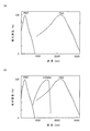
- the measurement step when the detector was switched was confirmed and compared with the case where the conventional spectroscopic measurement apparatus was used.
- the switching wavelength of the detector was set to 830 nm and 1650 nm, and three types of detectors (PMT detector, InGaAs detector, and PbS detector) were used. From the results shown in FIG. 6, it can be seen that the measurement step can be greatly reduced by using the spectroscopic measurement apparatus of this example.
- detectors having the same viewing angle are used, but a plurality of detectors having different detection angles can also be used.
- a detector mounting unit having a position adjusting unit that adjusts the positions of the detectors to match the detection visual fields of the plurality of detectors is used.
- An example of the detector mounting part 14b having the position adjusting part is shown in FIG. FIG. 7 (a) shows the size of the detection angle when the detector 14a is mounted as in the above embodiment, and FIG. 7 (b) shows the detection angle when the detector 14a is mounted away from the outer wall surface of the integrating sphere. Indicates the size. As can be seen from FIG.
- the effective detection angle can be changed by using the position adjustment unit and moving the detector 10a closer to or away from the outer wall surface of the integrating sphere. Accordingly, even when a plurality of types of detectors having different detection angles are used, their detection visual fields can be matched.
- each of the above-described embodiments is an example, and can be appropriately changed in accordance with the gist of the present invention.
- the case where each mounting portion can freely change the direction of the detector mounted on the mounting portion (movable) has been described as an example.
- a plurality of detectors to be used are determined in advance.
- a detector mounting portion may be used in which the detector is fixedly mounted in such a direction that the detection visual fields coincide with each other.
- a detector mounting portion may be used in which the detector is fixedly mounted in such a direction that the detection visual fields coincide with each other.
- the said Example although it was set as the structure provided with an at least 1 detector mounting part in a pole, it is not necessary to necessarily provide a detector mounting part in a pole. For example, as shown in FIG.
- detector mounting portions 13b and 15b may be provided, and detectors 13a and 15a may be mounted on them.
- the above-described embodiment is a spectroscopic measurement device that detects light diffusely reflected from a sample by introducing it from a light source outside the integrating sphere through a light introduction window and irradiating the sample.
- Integrating according to the present invention in various measuring apparatus such as a spectroscopic measuring apparatus for detecting and detecting the light transmitted through the sample inside the integrating sphere and a spectroscopic measuring apparatus having a light source arranged inside the integrating sphere A sphere can be used.
- An integrating sphere that does not include the light introduction window 2 is used as appropriate according to the configuration of the spectrometer.
Landscapes
- Physics & Mathematics (AREA)
- Spectroscopy & Molecular Physics (AREA)
- General Physics & Mathematics (AREA)
- Investigating Or Analysing Materials By Optical Means (AREA)
- Photometry And Measurement Of Optical Pulse Characteristics (AREA)
Abstract
Description
a) 試料から発せられる光を入射させる光入射窓、第1光検出窓、及び第2光検出窓を有する積分球本体と、
b) 前記第1光検出窓の外側に配置された第1検出器装着部と、
c) 前記第2光検出窓の外側に、装着される検出器の検出視野が、前記第1検出器装着部に装着される検出器の検出視野と一致するように配置された第2検出器装着部と
を備えることを特徴とする。
本発明に係る積分球では、第1検出器装着部に装着される検出器と第2検出器装着部に装着される検出器が同じ検出視野を有する。従って、本発明に係る積分球を用いると、同等の強度分布を有する検出視野から2つの検出器に光が入射するため、それらの検出器を切り替える際に生じる測定段差を軽減することができる。
図5に、本発明に係る積分球を備えた分光測定装置の一実施例の要部構成を示す。本実施例は、積分球外部の光源から発せられた光を光導入窓2を通して導入して試料4に照射し、試料4からの拡散反射光を検出する分光測定装置である。本実施例においても、既に述べたようにX軸、Y軸、及びZ軸を規定し、積分球とZ軸の交点を極点と呼ぶ。
上記実施例では、各装着部が、該装着部に装着される検出器の向きを自由に変更できる(可動である)場合を例に挙げて説明したが、使用する複数の検出器が予め決まっている場合には、それらの検出視野が一致するような向きに検出器を固定して装着する検出器装着部としてもよい。
また、上記実施例では、少なくとも1つの検出器装着部を極点に備える構成としたが、必ずしも極点に検出器装着部を備えなくてもよい。例えば、図8に示すように検出器装着部13b、15bを備え、それらに検出器13a、15aを装着するようにしてもよい。
さらに、上記実施例は、積分球外部の光源から光導入窓から導入して試料に照射し、試料からの拡散反射光を検出する分光測定装置であるが、積分球外部の光源から試料に光を照射し、該試料を透過した光を積分球内部に取り込んで検出する分光測定装置や、積分球内部に光源を配置する分光測定装置等、種々の構成の分光測定装置において本発明に係る積分球を用いることができる。なお、分光測定装置の構成に応じて、適宜、光導入窓2を備えない積分球を用いる。
2…光導入窓
3…光入射窓
4…試料
10、11、12、13、14、15…光検出窓
10a、11a、12a、13a、14a、15a…検出器
10b、11b、12b、13b、14b、15b…検出器装着部
Claims (3)
- a) 試料から発せられる光を入射させる光入射窓、第1光検出窓、及び第2光検出窓を有する積分球本体と、
b) 前記第1光検出窓の外側に配置された第1検出器装着部と、
c) 前記第2光検出窓の外側に、装着される検出器の検出視野が、前記第1検出器装着部に装着される検出器の検出視野と一致するように配置された第2検出器装着部と
を備えることを特徴とする分光測定装置用積分球。 - 前記第1検出器装着部及び/又は前記第2検出器装着部が、第1検出器装着部及び第2検出器装着部に装着される検出器の検出視野を一致させるために検出器の位置を調整する位置調整部を備えることを特徴とする請求項1に記載の分光測定装置用積分球。
- 請求項1又は2に記載の積分球を備えた分光測定装置。
Priority Applications (5)
| Application Number | Priority Date | Filing Date | Title |
|---|---|---|---|
| US15/300,329 US10094711B2 (en) | 2014-04-01 | 2014-04-01 | Spectrometer and integrating sphere |
| JP2016511251A JP6330900B2 (ja) | 2014-04-01 | 2014-04-01 | 分光測定装置及び積分球 |
| CN201480077731.4A CN106164632B (zh) | 2014-04-01 | 2014-04-01 | 分光测定装置及积分球 |
| EP14888029.7A EP3128302B1 (en) | 2014-04-01 | 2014-04-01 | Spectrometer and integrating sphere |
| PCT/JP2014/059660 WO2015151233A1 (ja) | 2014-04-01 | 2014-04-01 | 分光測定装置及び積分球 |
Applications Claiming Priority (1)
| Application Number | Priority Date | Filing Date | Title |
|---|---|---|---|
| PCT/JP2014/059660 WO2015151233A1 (ja) | 2014-04-01 | 2014-04-01 | 分光測定装置及び積分球 |
Publications (1)
| Publication Number | Publication Date |
|---|---|
| WO2015151233A1 true WO2015151233A1 (ja) | 2015-10-08 |
Family
ID=54239600
Family Applications (1)
| Application Number | Title | Priority Date | Filing Date |
|---|---|---|---|
| PCT/JP2014/059660 Ceased WO2015151233A1 (ja) | 2014-04-01 | 2014-04-01 | 分光測定装置及び積分球 |
Country Status (5)
| Country | Link |
|---|---|
| US (1) | US10094711B2 (ja) |
| EP (1) | EP3128302B1 (ja) |
| JP (1) | JP6330900B2 (ja) |
| CN (1) | CN106164632B (ja) |
| WO (1) | WO2015151233A1 (ja) |
Cited By (2)
| Publication number | Priority date | Publication date | Assignee | Title |
|---|---|---|---|---|
| WO2018020779A1 (ja) | 2016-07-25 | 2018-02-01 | 浜松ホトニクス株式会社 | 光計測装置 |
| JP2018194540A (ja) * | 2017-03-17 | 2018-12-06 | フルークコーポレイションFluke Corporation | 積分球を搭載した光学測定装置を使用した光コネクタの極性及び損失測定 |
Citations (4)
| Publication number | Priority date | Publication date | Assignee | Title |
|---|---|---|---|---|
| JP2002062189A (ja) * | 2000-08-24 | 2002-02-28 | Shimadzu Corp | 分光測定用検出器及びこれを用いた積分球測定器および分光光度計 |
| JP2006023284A (ja) * | 2004-06-11 | 2006-01-26 | Shimadzu Corp | 紫外可視近赤外分光光度計用検出装置 |
| JP2010261847A (ja) * | 2009-05-08 | 2010-11-18 | Konica Minolta Holdings Inc | 電子表示媒体評価システム |
| JP2012027353A (ja) * | 2010-07-27 | 2012-02-09 | Alps Electric Co Ltd | 光通信装置およびその組み立て方法 |
Family Cites Families (10)
| Publication number | Priority date | Publication date | Assignee | Title |
|---|---|---|---|---|
| US4932779A (en) * | 1989-01-05 | 1990-06-12 | Byk Gardner, Inc. | Color measuring instrument with integrating sphere |
| US5369481A (en) | 1992-05-08 | 1994-11-29 | X-Rite, Incorporated | Portable spectrophotometer |
| JP3464824B2 (ja) * | 1994-03-07 | 2003-11-10 | 株式会社リコー | 光学測定装置 |
| US6424413B1 (en) * | 1998-06-12 | 2002-07-23 | Gretagmacbeth Llc | Multi-channel integrating sphere |
| US6675030B2 (en) * | 2000-08-21 | 2004-01-06 | Euro-Celtique, S.A. | Near infrared blood glucose monitoring system |
| JP3318912B1 (ja) * | 2001-08-28 | 2002-08-26 | スガ試験機株式会社 | 三刺激値直読測色装置 |
| JP2009175026A (ja) * | 2008-01-25 | 2009-08-06 | Shimadzu Corp | 紫外可視近赤外分光光度計用検出装置 |
| CN201311325Y (zh) * | 2008-11-19 | 2009-09-16 | 中国计量科学研究院 | 积分球及使用积分球的光学测量系统 |
| JP5479543B2 (ja) * | 2012-07-19 | 2014-04-23 | 大塚電子株式会社 | 光学特性測定装置 |
| JP6185864B2 (ja) * | 2013-06-07 | 2017-08-23 | 本田技研工業株式会社 | 積分球 |
-
2014
- 2014-04-01 JP JP2016511251A patent/JP6330900B2/ja active Active
- 2014-04-01 EP EP14888029.7A patent/EP3128302B1/en active Active
- 2014-04-01 WO PCT/JP2014/059660 patent/WO2015151233A1/ja not_active Ceased
- 2014-04-01 CN CN201480077731.4A patent/CN106164632B/zh active Active
- 2014-04-01 US US15/300,329 patent/US10094711B2/en active Active
Patent Citations (4)
| Publication number | Priority date | Publication date | Assignee | Title |
|---|---|---|---|---|
| JP2002062189A (ja) * | 2000-08-24 | 2002-02-28 | Shimadzu Corp | 分光測定用検出器及びこれを用いた積分球測定器および分光光度計 |
| JP2006023284A (ja) * | 2004-06-11 | 2006-01-26 | Shimadzu Corp | 紫外可視近赤外分光光度計用検出装置 |
| JP2010261847A (ja) * | 2009-05-08 | 2010-11-18 | Konica Minolta Holdings Inc | 電子表示媒体評価システム |
| JP2012027353A (ja) * | 2010-07-27 | 2012-02-09 | Alps Electric Co Ltd | 光通信装置およびその組み立て方法 |
Non-Patent Citations (1)
| Title |
|---|
| See also references of EP3128302A4 * |
Cited By (5)
| Publication number | Priority date | Publication date | Assignee | Title |
|---|---|---|---|---|
| WO2018020779A1 (ja) | 2016-07-25 | 2018-02-01 | 浜松ホトニクス株式会社 | 光計測装置 |
| KR20190032268A (ko) | 2016-07-25 | 2019-03-27 | 하마마츠 포토닉스 가부시키가이샤 | 광 계측 장치 |
| US10928246B2 (en) | 2016-07-25 | 2021-02-23 | Hamamatsu Photonics K.K. | Optical measuring device comprising light receiving regions of light guide members overlap with each other in an integrator |
| JP2018194540A (ja) * | 2017-03-17 | 2018-12-06 | フルークコーポレイションFluke Corporation | 積分球を搭載した光学測定装置を使用した光コネクタの極性及び損失測定 |
| JP7381192B2 (ja) | 2017-03-17 | 2023-11-15 | フルークコーポレイション | 光学測定装置及びそれを用いた光学測定方法 |
Also Published As
| Publication number | Publication date |
|---|---|
| EP3128302A4 (en) | 2017-04-26 |
| CN106164632B (zh) | 2019-06-21 |
| US10094711B2 (en) | 2018-10-09 |
| JPWO2015151233A1 (ja) | 2017-04-13 |
| EP3128302B1 (en) | 2023-08-02 |
| JP6330900B2 (ja) | 2018-05-30 |
| CN106164632A (zh) | 2016-11-23 |
| US20170146398A1 (en) | 2017-05-25 |
| EP3128302A1 (en) | 2017-02-08 |
Similar Documents
| Publication | Publication Date | Title |
|---|---|---|
| JP2020517093A (ja) | エッチング処理監視のための高度先進光センサー、システム及び方法 | |
| CN106768855B (zh) | 一种大口径辐射计的光谱响应度测量装置及方法 | |
| JP6380662B2 (ja) | フーリエ変換型分光光度計 | |
| US20120314219A1 (en) | Device for referenced measurements of reflected light and a method for calibrating such a device | |
| US10088363B2 (en) | Biometric sensor and biometric analysis system including the same | |
| HU229699B1 (hu) | Pinhole kamerát alkalmazó, leképzõ optikai vizsgálóberendezés (reflektométer, polariméter, ellipszométer) | |
| US10180352B2 (en) | Measuring light source, and measuring system for detecting a reflection spectrum | |
| CN106574866B (zh) | 用于反射测量的测量装置 | |
| JP2007201475A (ja) | Euv放射線のための狭帯域透過フィルタ | |
| JP6330900B2 (ja) | 分光測定装置及び積分球 | |
| WO2016068504A1 (ko) | 다기능 분광장치 | |
| CN106052869A (zh) | 一种基于渐变滤光片分光的红外光谱辐射计 | |
| US20160109293A1 (en) | Illumination Device and Reflection Characteristic Measuring Device | |
| US20160238525A1 (en) | V-block refractometer | |
| TW201437604A (zh) | 能夠檢測顏色資訊的三維形狀檢測裝置 | |
| JP5929504B2 (ja) | 分光測定器 | |
| JP2018084523A5 (ja) | ||
| US6721050B2 (en) | Method and device for the spectral analysis of light | |
| US9658154B2 (en) | Spectrometer and gas analyzer | |
| US11054365B2 (en) | Microscopic analysis device | |
| US8427647B2 (en) | Cavity ring-down spectrometer systems | |
| JP2005172568A (ja) | 光学装置及びそれを有する測定装置 | |
| CN203083699U (zh) | 一种紫外光源均光装置 | |
| WO2018003045A1 (ja) | アパーチャ機能を有するビームスプリッタ及びそのビームスプリッタを備えた検出器 | |
| KR102085601B1 (ko) | 발광 소자의 지향 각 측정 장치 |
Legal Events
| Date | Code | Title | Description |
|---|---|---|---|
| 121 | Ep: the epo has been informed by wipo that ep was designated in this application |
Ref document number: 14888029 Country of ref document: EP Kind code of ref document: A1 |
|
| ENP | Entry into the national phase |
Ref document number: 2016511251 Country of ref document: JP Kind code of ref document: A |
|
| WWE | Wipo information: entry into national phase |
Ref document number: 15300329 Country of ref document: US |
|
| NENP | Non-entry into the national phase |
Ref country code: DE |
|
| REEP | Request for entry into the european phase |
Ref document number: 2014888029 Country of ref document: EP |
|
| WWE | Wipo information: entry into national phase |
Ref document number: 2014888029 Country of ref document: EP |