WO2015151246A1 - 部品実装機 - Google Patents
部品実装機 Download PDFInfo
- Publication number
- WO2015151246A1 WO2015151246A1 PCT/JP2014/059746 JP2014059746W WO2015151246A1 WO 2015151246 A1 WO2015151246 A1 WO 2015151246A1 JP 2014059746 W JP2014059746 W JP 2014059746W WO 2015151246 A1 WO2015151246 A1 WO 2015151246A1
- Authority
- WO
- WIPO (PCT)
- Prior art keywords
- nozzle
- replacement
- suction
- holders
- component
- Prior art date
- Legal status (The legal status is an assumption and is not a legal conclusion. Google has not performed a legal analysis and makes no representation as to the accuracy of the status listed.)
- Ceased
Links
Images






Classifications
-
- H—ELECTRICITY
- H05—ELECTRIC TECHNIQUES NOT OTHERWISE PROVIDED FOR
- H05K—PRINTED CIRCUITS; CASINGS OR CONSTRUCTIONAL DETAILS OF ELECTRIC APPARATUS; MANUFACTURE OF ASSEMBLAGES OF ELECTRICAL COMPONENTS
- H05K13/00—Apparatus or processes specially adapted for manufacturing or adjusting assemblages of electric components
- H05K13/04—Mounting of components, e.g. of leadless components
- H05K13/0404—Pick-and-place heads or apparatus, e.g. with jaws
- H05K13/0408—Incorporating a pick-up tool
-
- H—ELECTRICITY
- H05—ELECTRIC TECHNIQUES NOT OTHERWISE PROVIDED FOR
- H05K—PRINTED CIRCUITS; CASINGS OR CONSTRUCTIONAL DETAILS OF ELECTRIC APPARATUS; MANUFACTURE OF ASSEMBLAGES OF ELECTRICAL COMPONENTS
- H05K13/00—Apparatus or processes specially adapted for manufacturing or adjusting assemblages of electric components
- H05K13/08—Monitoring manufacture of assemblages
-
- H—ELECTRICITY
- H05—ELECTRIC TECHNIQUES NOT OTHERWISE PROVIDED FOR
- H05K—PRINTED CIRCUITS; CASINGS OR CONSTRUCTIONAL DETAILS OF ELECTRIC APPARATUS; MANUFACTURE OF ASSEMBLAGES OF ELECTRICAL COMPONENTS
- H05K13/00—Apparatus or processes specially adapted for manufacturing or adjusting assemblages of electric components
- H05K13/04—Mounting of components, e.g. of leadless components
- H05K13/0404—Pick-and-place heads or apparatus, e.g. with jaws
- H05K13/0408—Incorporating a pick-up tool
- H05K13/0409—Sucking devices
-
- H—ELECTRICITY
- H05—ELECTRIC TECHNIQUES NOT OTHERWISE PROVIDED FOR
- H05K—PRINTED CIRCUITS; CASINGS OR CONSTRUCTIONAL DETAILS OF ELECTRIC APPARATUS; MANUFACTURE OF ASSEMBLAGES OF ELECTRICAL COMPONENTS
- H05K13/00—Apparatus or processes specially adapted for manufacturing or adjusting assemblages of electric components
- H05K13/04—Mounting of components, e.g. of leadless components
- H05K13/0404—Pick-and-place heads or apparatus, e.g. with jaws
- H05K13/0408—Incorporating a pick-up tool
- H05K13/041—Incorporating a pick-up tool having multiple pick-up tools
Definitions
- the present invention relates to a component mounter capable of picking up a component by a suction nozzle and mounting it on a substrate.
- this type of component mounting machine includes a plurality of heads (a plurality of holders) that can attach and detach the suction nozzle and can move up and down independently of each other, and have the same number of components supplied from a plurality of component cassettes.
- adsorption nozzle a plurality of holders
- the component mounter Since the component mounter needs to use a suction nozzle suitable for suction according to the type (shape and size) of the component, it usually has a nozzle station that accommodates a plurality of suction nozzles in advance. Nozzle replacement work is performed to replace the suction nozzle attached to the holder. Although such nozzle replacement work is performed by automatic replacement by moving the head in the horizontal direction (XY axis direction) and moving the holder in the vertical direction (Z axis direction), the more types of parts to be mounted on the board, The number of necessary replacement operations increases. For this reason, in some cases, production is stopped due to the replacement operation of the suction nozzle, resulting in a decrease in production efficiency.
- the main object of the present invention is to further improve the production efficiency by providing a component mounting machine that can quickly perform the replacement operation of the suction nozzle.
- the present invention adopts the following means in order to achieve the main object described above.
- the component mounter of the present invention is A component mounter capable of picking up components with a suction nozzle and mounting them on a substrate, A head having a plurality of holders to which the suction nozzle can be attached and detached; Moving means capable of moving the head; Elevating means capable of elevating and lowering the plurality of holders independently; Nozzle container having a plurality of storage portions capable of storing the suction nozzles at the same interval as the intervals of the plurality of holders and storing a plurality of combinations of the suction nozzles that can be attached to the plurality of holders at a time.
- the suction means mounted on the plurality of holders controls the moving means so that the suction nozzles mounted on the plurality of holders respectively move to a position facing the storage unit to be stored among the plurality of storage units.
- Nozzle housing control for controlling the elevating means so that the nozzles are accommodated at once in the housing portions to be accommodated, and a plurality of holders to which the suction nozzles are not mounted are respectively mounted among the plurality of housing portions.
- the moving means is controlled so as to move to a position facing a housing portion where a set of target suction nozzles is housed, and the mounting target housed in the housing portion facing each of the plurality of holders is controlled.
- Nozzle replacement control means capable of executing nozzle mounting control for controlling the elevating means so that the suction nozzle is mounted at a time;
- a predetermined replacement condition for storing the suction nozzle stored in the replacement source storage unit among the plurality of storage units in the replacement destination storage unit is satisfied, a predetermined holder that is one of the plurality of holders is The moving means is controlled to move to a position facing the replacement source accommodating portion, and the lifting and lowering is performed so that the suction nozzle accommodated in the replacement source accommodating portion facing the predetermined holder is mounted.
- a head having a plurality of holders to which the suction nozzle can be attached and detached, a moving means capable of moving the heads, an elevating means capable of independently raising and lowering the plurality of holders, and a plurality of holders
- a nozzle container having a plurality of accommodating portions capable of accommodating a plurality of combinations of suction nozzles that can accommodate suction nozzles at the same interval as the interval and that can be attached to a plurality of holders at once, and a nozzle replacement control means.
- the nozzle replacement control means moves the suction nozzles mounted on the plurality of holders to positions facing the storage portions of the storage destination, and stores the suction nozzles mounted on the plurality of holders respectively.
- a set of suction nozzles to be attached to each of a plurality of holders to which the suction nozzles are not attached and a plurality of holders to which the suction nozzles are not attached are accommodated. Is moved to a position opposed to the volume unit, executes a nozzle attachment control for mounting a suction nozzle of the mounting object is received in the receiving portion which faces each at a time to a plurality of holders. Thereby, the efficiency of the replacement work can be improved as compared with the case where the suction nozzle replacement work is performed individually for each holder.
- the nozzle replacement control means moves the predetermined holder to a position facing the replacement source storage unit, and attaches the suction nozzle stored in the replacement source storage unit facing the predetermined holder,
- the suction nozzle mounted on the holder is moved to a position facing the replacement destination accommodating portion, and nozzle replacement control for accommodating the suction nozzle mounted on the predetermined holder in the replacement destination accommodating portion is performed.
- the nozzle replacement control can automatically change the combination of suction nozzles that can be attached to a plurality of holders at a time as necessary. As a result, the replacement operation of the suction nozzle can be performed efficiently, and a decrease in production efficiency can be suppressed.
- the component mounting machine includes an abnormality determining unit that determines abnormality of the suction nozzle, and the nozzle replacement control unit is configured to determine that the abnormality has occurred in the suction nozzle by the abnormality determination unit. Assuming that the replacement condition is satisfied, the spare suction nozzle stored in the replacement source storage unit is changed to the replacement destination storage unit that is the storage destination of the suction nozzle determined to have the abnormality. It can also be a means for performing the nozzle replacement control so as to be accommodated. In this way, since the suction nozzle in which an abnormality has occurred can be automatically replaced with a spare suction nozzle, a reduction in production efficiency can be suppressed even if an abnormality has occurred in the suction nozzle.
- the component mounting machine has a first lane and a second lane for transporting a board, mounting the component on the board transported to the first lane, and the second lane.
- the mounting of the components on the transported board can be performed in parallel, and the nozzle replacement control unit is producing one of the first lane and the second lane and completing the production of the other.
- the replacement destination storage unit that stores the pair of suction nozzles used for the other production is used for the next production.
- the nozzle replacement control may be performed so that the set of suction nozzles to be used is accommodated. In this way, it is possible to automatically change the setup for the next production type in the other lane while continuing the production in one lane.
- the nozzle replacement control means includes the nozzle in an idle time until the next substrate is transported after the mounting of the component on the substrate is completed and the substrate is discharged. It may be a means for performing replacement control. In this way, nozzle replacement control can be performed without stopping production.
- the nozzle replacement control means simultaneously uses the suction nozzles housed in the replacement source housing section and the suction nozzles housed in the replacement destination housing section in the plurality of holders. It can also be a means for switching the accommodation destinations of both suction nozzles to each other via the mounted state. By so doing, it is possible to replace a plurality of suction nozzles even when there is no space in the accommodating portion of the nozzle container. Further, the suction nozzle can be quickly replaced.
- FIG. 2 is a configuration diagram showing an outline of a configuration of a head 50.
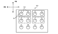
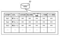
- FIG. 6 is an explanatory diagram showing an arrangement of sockets 62 of a nozzle station 60. 6 is an explanatory diagram illustrating an example of a production plan stored in an HDD 83 of the management device 80.
- FIG. 4 is a flowchart illustrating an example of a component mounting processing routine executed by a control device 70 of the component mounting machine 10. It is explanatory drawing explaining the mode of nozzle replacement
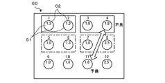
- FIG. 3 is a flowchart illustrating an example of a defective nozzle replacement process executed by a control device 70 of the component mounter 10. It is explanatory drawing explaining the accommodating place of the replacement
- FIG. 1 is a configuration diagram showing an outline of the configuration of a component mounter 10 as an embodiment of the present invention
- FIG. 2 shows details of an electrical connection relationship between a control device 70 and a management device 80 of the component mounter 10.
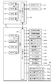
- FIG. 3 is a block diagram showing an outline of the configuration of the head 50.
- the left-right direction in FIG. 1 is the X-axis direction
- the front-rear direction is the Y-axis direction
- the up-down direction is the Z-axis direction.
- the component mounter 10 is a mounter that is suitable for mounting relatively large components or irregularly shaped components.
- the component mounter 10 includes a component supply device 16 that supplies a component P, a substrate transport device 20 that transports a substrate S, and a substrate S transported by the substrate transport device 20 from the back side.
- the substrate transfer device 20, the backup device 30, the head 50, and the XY robot 40 are accommodated in a main body frame 12 installed on the base 11.
- the component supply device 16 includes a feeder 18 that is arranged on the feeder base 14 formed on the front surface of the main body frame 12 so as to be aligned in the left-right direction (X-axis direction).
- the feeder 18 is a tape feeder that sends out a carrier tape containing the components P at a predetermined pitch to a component supply position where the suction nozzle 51 can pick up.
- the carrier tape is comprised by the bottom tape in which the cavity (recessed part) was formed with the predetermined pitch, and the top film which covers a bottom tape in the state in which the components P were accommodated in each cavity. .
- the feeder 18 pulls out the carrier tape wound around the reel, feeds it to the component supply position, and peels off the top film from the bottom tape before the component supply position, so that the component P is exposed at the component supply position, that is, the pickup. Make it possible.
- a tray feeder may be installed as the component supply device 16. The tray feeder accommodates trays in which plate-like components to be mounted on the substrate S are arranged in a stacked state, and supplies the components together with the trays.
- the substrate transfer device 20 is configured as a dual lane transfer device provided with two substrate transfer paths of a first lane 22 a and a second lane 22 b, and is a middle stage portion of the main body frame 12. It is arrange
- Each substrate transport path includes belt conveyor devices 24a and 24b, and the substrate S is transported from left to right (substrate transport direction) in FIG. 1 by driving the belt conveyor devices 24a and 24b.
- the backup device 30 includes a backup plate 32 that can be moved up and down by a lifting device (not shown), and a plurality of backup pins 34 that are erected on the backup plate 32.
- the backup device 30 backs up the substrate S from the back side by raising the backup plate 32 in a state where the substrate S is transported above the backup plate 32 by the substrate transport device 20.
- the XY robot 40 includes a Y-axis guide rail 43 provided in the upper stage portion of the main body frame 12 along the Y-axis direction, and a Y-axis slider capable of moving along the Y-axis guide rail 43. 44, an X-axis guide rail 41 provided along the X-axis direction on the lower surface of the Y-axis slider 44, and an X-axis slider 42 movable along the X-axis guide rail 41.
- the aforementioned mark camera 46 is attached to the lower surface of the X-axis slider 42.
- the head 50 is a shaft-like member extending in the Z-axis direction, and extends in the Z-axis direction in the same manner as a first nozzle holder 52a that detachably holds the suction nozzle 51 by a nozzle chuck (not shown).
- a second nozzle holder 52b which is a shaft-like member and is arranged to be aligned with the first nozzle holder 52a in the left-right direction (X-axis direction) and detachably holds the suction nozzle 51 by a nozzle chuck (not shown);
- a first Z-axis actuator 54a that moves one nozzle holder 52a in the vertical direction (Z-axis direction), and a second Z-axis actuator 54b that moves the second nozzle holder 52b in the vertical direction (Z-axis direction).
- the first ⁇ -axis actuator 56a that rotates the first nozzle holder 52a around the axis and the second nozzle holder 52b that rotates around the axis And a second ⁇ -axis actuator 56b to.
- the head 50 includes the Z-axis actuators 54a and 54b and the ⁇ -axis actuators 56a and 56b for each of the nozzle holders 52a and 52b
- the nozzle holders 52a and 52b are independently provided in the Z-axis direction and the ⁇ -axis direction ( Rotation direction).
- Each of the nozzle holders 52a and 52b has internal passages 53a and 53b that communicate with the suction port of the suction nozzle 51 attached thereto.
- the internal passages 53a and 53b selectively communicate with either the vacuum pump 57 or the air pipe 58 through the corresponding solenoid valves (first solenoid valve 59a and second solenoid valve 59b). Yes.
- the suction port of the suction nozzle 51 attached to the first nozzle holder 52a when the first electromagnetic valve 59a is driven so that the internal passage 53a of the first nozzle holder 52a communicates with the vacuum pump 57, the suction port of the suction nozzle 51 attached to the first nozzle holder 52a. A negative pressure acts on the component P, and the component P can be adsorbed. Further, when the solenoid valve 59a is driven so that the internal passage 53a of the first nozzle holder 52a and the air pipe 58 communicate with each other, a positive pressure is applied to the suction port of the suction nozzle 51 attached to the first nozzle holder 52a. Acts to release the adsorption of the component P.
- the two left and right nozzle holders 52a and 52b are arranged at substantially the same interval as the interval between the component supply positions of the two feeders 18 adjacent to the left and right. Accordingly, the suction nozzle 51 is attached to each of the two nozzle holders 52a and 52b, and the head 50 is placed so that the two attached suction nozzles 51 come to positions facing the respective component supply positions of the two adjacent feeders 18. By moving and lowering the two suction nozzles 51 and applying a negative pressure to the suction port of the suction nozzle 51, the two suction nozzles 51 can simultaneously suck the component P.
- the nozzle station 60 includes a plurality of sockets 62 that can accommodate different types (nozzle diameters) of suction nozzles 51.
- FIG. 4 is an explanatory diagram showing the arrangement of the sockets 62 of the nozzle station 60.
- the number described above each socket 62 in a figure shows a socket number
- the number described in each adsorption nozzle 51 (circle) shows the diameter (mm) of a nozzle. This also applies to FIGS. 9 and 13 described later.
- the interval between the left and right adjacent sockets is substantially the same as the two left and right nozzle holders 52a and 52b.
- the head 50 is moved so that the two nozzle holders 52a and 52b, to which the suction nozzle 51 is mounted, are respectively positioned opposite to the two left and right empty sockets 62 among the plurality of sockets 62.
- the suction nozzles 51 mounted on the two nozzle holders 52a and 52b are returned to the two sockets 62 at once ( Can be returned at the same time).
- the head 50 is moved so that the two nozzle holders 52a and 52b are opposed to the two sockets 62 that accommodate the suction nozzles 51, and the two nozzle holders 52a and 52b are moved down so that the two nozzle holders 52a, 52b,
- the two suction nozzles 51 can be attached to the two nozzle holders 52a and 52b at the same time (simultaneous attachment).
- simultaneous return and simultaneous mounting are collectively referred to as simultaneous replacement.
- the management device 80 determines the position of each suction nozzle 51 on the nozzle station 60 according to a production plan described later, and sets the suction nozzle 51 according to the determined position.
- An instruction screen is output on the display 88 to the worker.
- the suction nozzle 51 is provided with an identification code (not shown) at a position (the upper surface of the flange portion of the suction nozzle 51) that can be viewed in the state of being accommodated in the socket 62.
- the control device 70 can identify the types of all the suction nozzles 51 accommodated in the nozzle station 60 by imaging the identification code with the mark camera 46 before production.
- the control device 70 is configured as a microprocessor centered on the CPU 71, and includes a ROM 72, an HDD 73, a RAM 74, and an input / output interface 75 in addition to the CPU 71. These are electrically connected via a bus 76.
- the control device 70 includes a position signal from the X-axis position sensor 42 a that detects the position of the X-axis slider 42, a position signal from the Y-axis position sensor 44 a that detects the position of the Y-axis slider 44, and an image from the mark camera 46. Signals, image signals from the parts camera 48, and the like are input via the input / output interface 75.
- a control signal to the component supply device 16 a control signal to the substrate transfer device 20, a control signal to the backup device 30, a drive signal to the X-axis actuator 42 b that moves the X-axis slider 42, A drive signal to the Y-axis actuator 44b for moving the Y-axis slider 44, a control signal to the head 50 (the first Z-axis actuator 54a, the second Z-axis actuator 54b, the first ⁇ -axis actuator 56a, the second Drive signals to the ⁇ -axis actuator 56b), drive signals to the solenoid valves (first solenoid valve 59a, second solenoid valve 59b), and the like are output via the input / output interface 75.
- the control device 70 is connected to the management device 80 via a communication network so as to be capable of bidirectional communication, and exchanges data and control signals with each other.
- the management device 80 is, for example, a general-purpose computer, and includes a CPU 81, a ROM 82, an HDD 83, a RAM 84, an input / output interface 85, and the like. These are electrically connected via a bus 86.
- An input signal is input to the management device 80 from an input device 87 such as a mouse or a keyboard via an input / output interface 85, and an image signal to the display 88 is output from the management device 80 via the input / output interface 85.
- the HDD 83 stores a production plan for the substrate S.
- the production plan of the substrate S is what component P is mounted on the substrate S in which order in each component mounting machine 11, how many substrates S on which the component P is mounted are produced.
- a plan that defines FIG. 5 shows an example of a production plan stored in the HDD 83.
- the production plan includes the types of production lanes, the number of substrates S to be manufactured, the component information about the components P to be mounted on the substrate S, the feeder information about the feeder 18 to be used, the head information about the head 50 to be used, and the usage.
- the nozzle information related to the suction nozzle 51 to be performed is included. These pieces of information are stored in the HDD 83 in association with the production numbers.
- the feeder information includes the installation position of each feeder 18, the type of component P supplied by each feeder 18, and the like.
- the nozzle information includes the type (nozzle diameter) of the suction nozzle 51 accommodated in each socket 62 on the nozzle station 60, information on which lane is attached to which nozzle holder 52, and in which order. including.
- a production plan is input to the management device 80 by the operator operating the input device 87.
- the management device 80 outputs a command signal to the component mounter 10 so that the component P is mounted on the board S according to the production plan.
- FIG. 6 is a flowchart illustrating an example of a component mounting process routine executed by the CPU 71 of the control device 70. This routine is executed when a command signal is received from the management device 80.
- the CPU 71 of the control device 70 first determines whether or not the board S has been loaded onto the first lane 22a (step S100).
- the backup device 30 positions the substrate S.
- the CPU 71 determines that the substrate S is not loaded, the CPU 71 proceeds to the process of step S170.
- the CPU 71 determines whether or not the suction nozzle 51 needs to be replaced (nozzle replacement) (step S110). The determination in step S110 can be made based on nozzle information included in the production plan received from the management device 80.
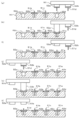
- FIG. 7 is an explanatory diagram showing how the suction nozzles mounted on the nozzle holders 52a and 52b are replaced from the suction nozzles 51a and 51b to the suction nozzles 51c and 51d.
- “a to d” of the sockets 62a to 62d are symbols given for convenience in order to distinguish the sockets from each other, and “a to d” of the suction nozzles 51a to 51d indicate the suction nozzles to each other.
- Nozzle replacement is performed as follows. That is, the CPU 71 first causes the head 50 to move until the suction nozzles 51a and 51b currently mounted on the nozzle holders 52a and 52b come to positions facing the sockets 62a and 62b that are the accommodation destinations. 40 (X-axis actuator 42b, Y-axis actuator 44b) is controlled (see FIG. 7A). Subsequently, the CPU 71 controls the Z-axis actuators 54a and 54b so that the nozzle holders 52a and 52b are moved downward, and releases the holding of the suction nozzles 51a and 51b by the nozzle holders 52a and 52b.
- the CPU 71 controls the Z-axis actuators 54a and 54b so that the nozzle holders 52a and 52b are raised (see FIG. 7C), and the nozzle holders 52a and 52b are accommodated in the replacement suction nozzles 51c and 51d, respectively.
- the XY robot 40 is controlled so that the head 50 moves until it comes to a position facing the sockets 62c and 62d (see FIG. 7D).
- the CPU 71 controls the Z-axis actuators 54a and 54b so that the nozzle holders 52a and 52b are lowered, and the sockets are connected to the nozzle holders 52a and 52b.
- the suction nozzles 51c and 51d respectively accommodated in 62c and 62d are mounted (see FIG. 7E), and the Z-axis actuators 54a and 54b are controlled so that the nozzle holders 52a and 52b are raised (FIG. 7F). reference).
- the CPU 71 sucks the component P supplied from the feeder 18 by the suction nozzle 51 mounted on the nozzle holders 52a and 52b, respectively (step S130).
- the suction nozzles 51a and 51b are respectively attached to the left and right nozzle holders 52a and 52b, the parts P supplied from the two feeders 18 adjacent to the left and right are respectively replaced with the two suction nozzles 51a and 51b.
- the CPU 71 controls the XY robot 40 so that the two suction nozzles 51a and 51b come directly above the parts P supplied by the two target feeders 18, respectively.
- the CPU 71 controls the Z-axis actuators 54a and 54b so that the nozzle holders 52a and 52b are lowered until the suction ports of the two suction nozzles 51a and 51b come into contact with the two parts P immediately below, respectively.
- the electromagnetic valves 59a and 59b are controlled so that a negative pressure acts on the suction ports of the nozzles 51a and 51b, and the component P is simultaneously sucked by the two suction nozzles 51a and 51b.
- step S140 when the component P is attracted to the suction nozzle 51, the CPU 71 moves the attracted component P onto the substrate S and mounts it on the mounting position of the substrate S (step S140). Specifically, the process of step S140 is performed as follows. That is, when the suction nozzles 51a and 51b are mounted on the two nozzle holders 52a and 52b, the CPU 71 causes the component P sucked by the suction nozzle 51a to be directly above the mounting position of the substrate S. To control. Then, the CPU 71 controls the first Z-axis actuator 54a so that the suction nozzle 51a is lowered until the component P is pressed against the mounting position, and the first electromagnetic is applied to the suction port of the suction nozzle 51a.
- the component P sucked by the suction nozzle 51a is mounted on the substrate S by controlling the valve 59a.
- the CPU 71 controls the XY robot 40 so that the component P sucked by the suction nozzle 51b is directly above the mounting position.
- the CPU 71 controls the second Z-axis actuator 54b so that the suction nozzle 51b descends until the component P is pressed against the mounting position, and the second electromagnetic wave is applied to the suction port of the suction nozzle 51b.
- the component P sucked by the suction nozzle 51b is mounted on the substrate S by controlling the valve 59b.
- the CPU 71 mounts the component P sucked by the suction nozzle 51b after mounting the component P sucked by the suction nozzle 51a, but the component P sucked by the suction nozzle 51b. It is good also as what mounts the components P made to adsorb
- the CPU 71 moves the component P above the parts camera 48 and picks up an image with the part camera 48, and sucks based on the obtained image. It is determined whether or not the nozzles 51a and 51b are normally sucking the component P, and the mounting position is corrected based on the determination result.
- the CPU 71 determines whether or not all the components P to be mounted on the substrate S by the component mounter 10 have been mounted (step S150), and all the components P are mounted. If it is determined that the process has not been completed, the process returns to step S110, the nozzle replacement process is performed as necessary, and the mounting operation of steps S120 to S140 is repeated. When the CPU 71 determines that all the components P have been mounted, the CPU 71 controls the substrate transfer device 20 to pay out the substrate S (step S160), and proceeds to the next step S170.
- the CPU 71 determines whether or not the substrate S has been loaded onto the second lane 22b (step S170). If it is determined that the substrate S has not been loaded, the process returns to step S100, and the substrate S is loaded. If it is determined that the nozzles have been mounted, the nozzle replacement work corresponding to the type of the component P to be mounted is performed, and then the two components P are simultaneously picked up and mounted at the corresponding mounting positions, and the mounting operation is completed. Then, a mounting operation for paying out the substrate S is performed (steps S180 to S230). Note that the processes in steps S180 to S230 are the same as those in steps S110 to S160 except that the target lanes are different, and thus detailed description thereof is omitted.
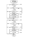
- FIG. 8 is a flowchart showing an example of the defective nozzle replacement process executed by the CPU 71 of the control device 70. This process is repeatedly executed every predetermined time.
- the CPU 71 first determines the abnormality of the suction nozzles housed on the nozzle station 60 and the suction nozzles mounted on the nozzle holders 52a and 52b (step S300).
- the abnormality of the suction nozzle for example, when the identification code attached to the suction nozzle 51 on the nozzle station 60 is imaged with the mark camera 46 at the start of production, the type of the suction nozzle is specified.
- the suction nozzle 51 is bent or missing.
- the suction failure of the component P sucked to the suction nozzle 51 during production occurs at a predetermined frequency or more, the nozzle holders 52a, 52b (inside And the like when detecting nozzle clogging by the vacuum sensor (not shown) for detecting the vacuum pressure and vacuum flow passages 53a, 53b). If the CPU 71 determines that there is no abnormality in any of the determination target suction nozzles, the defective nozzle replacement process is terminated.
- the production is interrupted (step S320), and the nozzle replacement for replacing the defective nozzle with the spare nozzle is performed.
- step S330 the production is resumed (step S340), and the defective nozzle replacement process is terminated.
- the defective nozzle accommodation destination (No. 4 socket) and the spare nozzle accommodation destination (No. 11 socket) of the same type (nozzle diameter) as the defective nozzle are exchanged with each other. Is. FIG. 10 and FIG.
- FIG. 11 are explanatory diagrams showing a state in which the suction nozzle 51a (defective nozzle) accommodated in the socket 62a and the suction nozzle 51d (preliminary nozzle) accommodated in the socket 62d are exchanged.
- the nozzle replacement process is performed as follows. That is, as shown in the figure, the CPU 71 first controls the XY robot 40 so that the head 50 moves until the first nozzle holder 52a comes to a position facing the socket 62a that is the storage destination of the defective nozzle (FIG. 10). (See (a)).
- the CPU 71 controls the first Z-axis actuator 54a so that the first nozzle holder 52a is lowered, and the first nozzle holder 52a holds the suction nozzle 51a (defective nozzle), whereby the first The suction nozzle 51a (defective nozzle) is mounted on the nozzle holder 52a (see FIG. 10B). Then, the CPU 71 controls the first Z-axis actuator 54a so that the first nozzle holder 52a moves up (see FIG. 10C), and the suction nozzle 51d (preliminary) from which the second nozzle holder 52b is replaced.
- the XY robot 40 is controlled so that the head 50 moves until it comes to a position facing the socket 62d in which the nozzle) is accommodated (see FIG. 10D).
- the CPU 71 controls the second Z-axis actuator 54b so that the second nozzle holder 52b descends, and the second nozzle holder 52b is sucked.
- the nozzle 51d separe nozzle
- the suction nozzle 51d is mounted on the second nozzle holder 52b (see FIG. 10E)
- the second nozzle holder 52b is raised.
- the second Z-axis actuator 54b is controlled (see FIG. 10F).
- the two nozzle holders 52a and 52b are in a state where both the suction nozzle 51a (defective nozzle) and the suction nozzle 51d (preliminary nozzle) are mounted.
- the CPU 71 comes to a position where the first nozzle holder 52a to which the suction nozzle 51a (defective nozzle) is attached faces the socket 62d that is in an empty state after taking out the suction nozzle 51d (preliminary nozzle).
- the XY robot 40 is controlled so that the head 50 moves until the head 50 moves (see FIG. 11G)
- the first Z-axis actuator 54a is controlled so that the first nozzle holder 52a is lowered, and the first nozzle holder 52a
- the holding of the suction nozzle 51a (defective nozzle) is released, and the suction nozzle 51a (defective nozzle) is accommodated in the socket 62d (see FIG. 11H).
- the CPU 71 controls the first Z-axis actuator 54a so that the first nozzle holder 52a moves up (see FIG. 11 (i)), and the second nozzle that is equipped with the suction nozzle 51d (preliminary nozzle).
- the XY robot 40 is controlled so that the head 50 moves until the holder 52b comes out of the suction nozzle 51a (defective nozzle) and comes to a position facing the socket 62a that is in an empty state (see FIG. 11J).
- the second Z-axis actuator 54b is controlled so that the second nozzle holder 52b is lowered, the suction nozzle 51d (preliminary nozzle) held by the second nozzle holder 52b is released, and the suction nozzle 51d (preliminary nozzle) is inserted into the socket 62a. ) (See FIG. 11 (k)).
- the CPU 71 controls the second Z-axis actuator 54b so that the second nozzle holder 52b is raised (see FIG. 11L), and the nozzle replacement process. Is completed.
- the suction nozzle 51a accommodated in the replacement-destination socket 62a is mounted first, and the suction nozzle 51d accommodated in the replacement-source socket 62d is mounted later, but the mounting order is reversed. May be.
- the socket 62 has no space. Even if it exists, the two suction nozzles 51a and 51d can be automatically replaced.
- FIG. 12 is a flowchart showing an example of a nozzle change process at the time of changeover executed by the CPU 71 of the control device 70. This process is repeatedly executed every predetermined time.
- the CPU 71 first determines whether or not the setup change has occurred after the production of the first lane 22a is completed (step S400). If the CPU 71 determines that the setup change of the first lane 22a has not occurred, the CPU 71 proceeds to the process of step S450. If the CPU 71 determines that the setup change of the first lane 22a has occurred, the state of the second lane 22b is produced.
- step S410 It is determined whether it is in the middle (step S410), and if it is in production, it is determined whether it is in a board loading waiting state (step S420). If the CPU 71 determines that the state of the second lane 22b is not in production, or determines that the second lane 22b is in a production waiting state even when the second lane 22b is in production, the management device 80 determines that the next lane 22a is in the next state.
- a production plan relating to production is acquired (step S430), and nozzle replacement processing is executed according to the acquired production plan (step S440).
- the CPU 71 determines whether or not the setup change occurs after the production of the second lane 22b is completed (step S450). When the CPU 71 determines that the setup change of the second lane 22b has not occurred, the CPU 71 ends the nozzle change process at the setup change, and determines that the setup change of the second lane 22b has occurred, It is determined whether or not the state is in production (step S460), and if it is in production, it is determined whether or not the substrate is waiting to be carried in (step S470).
- the CPU 71 determines that the state of the first lane 22a is not in production, or determines that the first lane 22a is in a state of waiting for board loading even when the first lane 22a is in production, the CPU 71 sets the next lane 22b to the next lane 22b.
- a production plan relating to production is acquired (step S480), nozzle replacement processing is executed according to the acquired production plan (step S490), and the nozzle replacement processing at the time of setup change is completed.
- the nozzle replacement process at the time of setup change is a process of replacing the combination of the suction nozzles 51 used in the previous production with the combination of the suction nozzles used in the next production.
- a nozzle having a nozzle diameter of 1.0 mm, a nozzle having a nozzle diameter of 1.3 mm, and a nozzle diameter of 1 in the fifth to eighth sockets, respectively. .8mm nozzle and nozzle diameter 2.5mm are housed, and in the next production in the second lane 22b, nozzles with a nozzle diameter of 1.0mm and nozzle diameters in the 5th to 8th sockets respectively.
- the CPU 71 replaces the nozzle having a nozzle diameter of 1.3 mm accommodated in the No. 6 socket with the spare nozzle having a nozzle diameter of 1.0 mm accommodated in the No. 9 socket, and accommodated in the No. 7 socket.
- What is necessary is just to perform the process which replaces the nozzle with a nozzle diameter of 1.8 mm and the reserve nozzle with a nozzle diameter of 2.5 mm accommodated in 12th socket.
- the nozzle replacement process in this case can be performed by the same process as the above-described defective nozzle replacement process.
- the component mounting machine 10 includes the nozzle station 60 having the plurality of sockets 62 that accommodate the suction nozzles 51 at the same intervals as the intervals between the plurality of nozzle holders 52a and 52b to which the suction nozzles 51 can be attached and detached.
- the suction nozzles 51a, 51b mounted on the plurality of nozzle holders 52a, 52b are moved to positions facing the receiving sockets 62a, 62b, respectively, and the suction nozzle 51a mounted on the plurality of nozzle holders 52a, 52b.
- the component mounter 10 of the present embodiment moves one nozzle holder 52b of the nozzle holders 52a and 52b to a position facing the replacement source socket 62d, and the replacement source facing the one nozzle holder 52b.
- the suction nozzle 51d accommodated in the socket 62d is mounted, the suction nozzle 51d mounted in one nozzle holder 52b is moved to a position facing the replacement destination socket 62a, and the suction nozzle 51d mounted in one nozzle holder 52b.
- the nozzle replacement process is automatically performed by accommodating the nozzle 51d in the replacement destination socket 62a. That is, the combination of suction nozzles that can be attached to the plurality of nozzle holders 52a and 52b at a time can be automatically changed as necessary by the nozzle replacement process. As a result, the replacement operation of the suction nozzle can be performed efficiently, and a decrease in production efficiency can be suppressed.
- the component mounter 10 of the present embodiment performs the nozzle replacement process via a state where the two suction nozzles 51a and 51d to be replaced are simultaneously mounted on both of the two nozzle holders 52a and 52b. Even in a state where there is no space in 62, the two suction nozzles 51a and 51d can be automatically replaced and the nozzles can be replaced quickly.
- the component mounter 10 of the present embodiment performs the nozzle replacement process when a defective nozzle occurs, it can be automatically restored even when a defective nozzle occurs during production. Furthermore, the component mounter 10 according to the present embodiment, when one of the first lane 22a and the second lane 22b is in production and a change of setup occurs in the other lane, the board loading in one of the lanes in production Since the suction nozzle 51 used for the next production in the other lane is replaced using the waiting state (free time), the setup change for the next production type in the other lane is automatically performed while continuing the production in the other lane. Can be done.
- the component mounter 10 performs the nozzle replacement process through a state in which the two suction nozzles 51a and 51d to be replaced are simultaneously mounted on both of the two nozzle holders 52a and 52b. It is not limited to.
- the suction nozzle accommodated in the replacement destination socket is attached to one of the nozzle holders 52a and 52b, and is temporarily accommodated in the empty socket and accommodated in the replacement source socket.
- the suction nozzle that has been used is attached to one of the nozzle holders 52a and 52b and accommodated in the replacement destination socket, and the suction nozzle that is accommodated in the empty socket is attached to either of the nozzle holders 52a and 52b.
- the state of the other lane is loaded into the board when the other lane is in production.
- the nozzle replacement process is performed during the waiting state (free time).
- the present invention is not limited to this, and the nozzle replacement process may be executed by temporarily stopping the production of the other lane. Good.
- the component mounter 10 includes the two nozzle holders 52a and 52b, but may include three or more nozzle holders.
- the nozzle station 60 may arrange a plurality of sockets so that suction nozzles can be simultaneously mounted on three or more nozzle holders.
- the component mounter 10 corresponds to “component mounter”
- the nozzle holders 52a and 52b correspond to “plural holders”
- the XY robot 40 corresponds to “moving means”
- the Z-axis actuators 54a and 54b Corresponding to “elevating means”
- the nozzle station 60 corresponds to “nozzle container”
- the CPU 71 of the control device 70 executing the processing of step S120 and step S190 of the component mounting processing routine of FIG.
- the CPU 71 of the control device 70 that executes the processing of step S330 of the defective nozzle replacement process in FIG.
- nozzle replacement control means corresponds to “nozzle replacement control means”.
- the CPU 71 of the control device 70 that executes the process of step S300 of the defective nozzle replacement process of FIG. 8 corresponds to “abnormality determination means”.
- the present invention can be used in the component mounter manufacturing industry.
Landscapes
- Engineering & Computer Science (AREA)
- Manufacturing & Machinery (AREA)
- Microelectronics & Electronic Packaging (AREA)
- Operations Research (AREA)
- Supply And Installment Of Electrical Components (AREA)
Abstract
Description
吸着ノズルにより部品をピックアップして基板上に実装可能な部品実装機であって、
前記吸着ノズルを着脱可能な複数のホルダを有するヘッドと、
前記ヘッドを移動可能な移動手段と、
前記複数のホルダを独立して昇降可能な昇降手段と、
前記複数のホルダの間隔と同じ間隔で前記吸着ノズルを収容可能であって前記複数のホルダに対して一度に装着できる前記吸着ノズルの組み合わせを複数組収容可能な複数の収容部を有するノズル収容器と、
前記複数のホルダに装着されている吸着ノズルがそれぞれ前記複数の収容部のうち収容対象の収容部に対向する位置まで移動するよう前記移動手段を制御し、前記複数のホルダに装着されている吸着ノズルがそれぞれ対向する前記収容対象の収容部に一度に収容されるよう前記昇降手段を制御するノズル収容制御と、前記吸着ノズルが装着されていない複数のホルダがそれぞれ前記複数の収容部のうち装着対象の吸着ノズルの組が収容されている収容部に対向する位置まで移動するよう前記移動手段を制御し、前記複数のホルダに対してそれぞれ対向する前記収容部に収容されている前記装着対象の吸着ノズルが一度に装着されるよう前記昇降手段を制御するノズル装着制御とを実行可能なノズル交換制御手段と、
前記複数の収容部のうち入替元の収容部に収容されている吸着ノズルを入替先の収容部に収容する所定の入替条件が成立した場合、前記複数のホルダのいずれかである所定のホルダが前記入替元の収容部に対向する位置まで移動するよう前記移動手段を制御し、前記所定のホルダに対して対向する前記入替元の収容部に収容されている吸着ノズルが装着されるよう前記昇降手段を制御し、前記所定のホルダに装着された吸着ノズルが前記入替先の収容部に対向する位置まで移動するよう前記移動手段を制御し、前記所定のホルダに装着された吸着ノズルが前記入替先の収容部に収容されるよう前記昇降手段を制御するノズル入替制御を行うノズル入替制御手段と
を備えることを要旨とする。
Claims (5)
- 吸着ノズルにより部品をピックアップして基板上に実装可能な部品実装機であって、
前記吸着ノズルを着脱可能な複数のホルダを有するヘッドと、
前記ヘッドを移動可能な移動手段と、
前記複数のホルダを独立して昇降可能な昇降手段と、
前記複数のホルダの間隔と同じ間隔で前記吸着ノズルを収容可能であって前記複数のホルダに対して一度に装着できる前記吸着ノズルの組み合わせを複数組収容可能な複数の収容部を有するノズル収容器と、
前記複数のホルダに装着されている吸着ノズルがそれぞれ前記複数の収容部のうち収容対象の収容部に対向する位置まで移動するよう前記移動手段を制御し、前記複数のホルダに装着されている吸着ノズルがそれぞれ対向する前記収容対象の収容部に一度に収容されるよう前記昇降手段を制御するノズル収容制御と、前記吸着ノズルが装着されていない複数のホルダがそれぞれ前記複数の収容部のうち装着対象の吸着ノズルの組が収容されている収容部に対向する位置まで移動するよう前記移動手段を制御し、前記複数のホルダに対してそれぞれ対向する前記収容部に収容されている前記装着対象の吸着ノズルが一度に装着されるよう前記昇降手段を制御するノズル装着制御とを実行可能なノズル交換制御手段と、
前記複数の収容部のうち入替元の収容部に収容されている吸着ノズルを入替先の収容部に収容する所定の入替条件が成立した場合、前記複数のホルダのいずれかである所定のホルダが前記入替元の収容部に対向する位置まで移動するよう前記移動手段を制御し、前記所定のホルダに対して対向する前記入替元の収容部に収容されている吸着ノズルが装着されるよう前記昇降手段を制御し、前記所定のホルダに装着された吸着ノズルが前記入替先の収容部に対向する位置まで移動するよう前記移動手段を制御し、前記所定のホルダに装着された吸着ノズルが前記入替先の収容部に収容されるよう前記昇降手段を制御するノズル入替制御を行うノズル入替制御手段と
を備えることを特徴とする部品実装機。 - 請求項1記載の部品実装機であって、
前記吸着ノズルの異常を判定する異常判定手段を備え、
前記ノズル入替制御手段は、前記異常判定手段により前記吸着ノズルに異常が生じていると判定された場合に、前記入替条件が成立したとして、前記入替元の収容部に収容されている予備の吸着ノズルが、前記異常が生じていると判定された吸着ノズルの収容先である前記入替先の収容部に収容されるよう前記ノズル入替制御を行う手段である
ことを特徴とする部品実装機。 - 請求項1または2記載の部品実装機であって、
基板を搬送する第1のレーンと第2のレーンとを有し、
前記第1のレーンに搬送された基板へ部品の実装と、前記第2のレーンに搬送された基板への部品の実装とを並行して実行可能であり、
前記ノズル入替制御手段は、前記第1のレーンおよび前記第2のレーンの一方が生産中であり、他方の生産が完了し次の生産種への段取替えを行う場合に、前記入替条件が成立したとして、前記他方の生産に用いられた吸着ノズルの組が収容される前記入替先の収容部に、次の生産に用いられる吸着ノズルの組が収容されるよう前記ノズル入替制御を行う手段である
ことを特徴とする部品実装機。 - 請求項1ないし3いずれか1項に記載の部品実装機であって、
前記ノズル入替制御手段は、前記基板への部品の実装が完了して該基板を払い出した後、次の基板が搬送されてくるまでの空き時間に前記ノズル入替制御を行う手段である
ことを特徴とする部品実装機。 - 請求項1ないし4いずれか1項に記載の部品実装機であって、
前記ノズル入替制御手段は、前記複数のホルダに前記入替元の収容部に収容された吸着ノズルと前記入替先の収容部に収容された吸着ノズルとを同時に装着している状態を経由して、両吸着ノズルの収容先を互いに入れ替える手段である
ことを特徴とする部品実装機。
Priority Applications (5)
| Application Number | Priority Date | Filing Date | Title |
|---|---|---|---|
| JP2016511261A JP6279716B2 (ja) | 2014-04-02 | 2014-04-02 | 部品実装機 |
| US15/129,644 US10362719B2 (en) | 2014-04-02 | 2014-04-02 | Component mounting machine |
| CN201480077460.2A CN106105419B (zh) | 2014-04-02 | 2014-04-02 | 元件安装机 |
| EP14887953.9A EP3128824B1 (en) | 2014-04-02 | 2014-04-02 | Component mounting machine |
| PCT/JP2014/059746 WO2015151246A1 (ja) | 2014-04-02 | 2014-04-02 | 部品実装機 |
Applications Claiming Priority (1)
| Application Number | Priority Date | Filing Date | Title |
|---|---|---|---|
| PCT/JP2014/059746 WO2015151246A1 (ja) | 2014-04-02 | 2014-04-02 | 部品実装機 |
Publications (1)
| Publication Number | Publication Date |
|---|---|
| WO2015151246A1 true WO2015151246A1 (ja) | 2015-10-08 |
Family
ID=54239609
Family Applications (1)
| Application Number | Title | Priority Date | Filing Date |
|---|---|---|---|
| PCT/JP2014/059746 Ceased WO2015151246A1 (ja) | 2014-04-02 | 2014-04-02 | 部品実装機 |
Country Status (5)
| Country | Link |
|---|---|
| US (1) | US10362719B2 (ja) |
| EP (1) | EP3128824B1 (ja) |
| JP (1) | JP6279716B2 (ja) |
| CN (1) | CN106105419B (ja) |
| WO (1) | WO2015151246A1 (ja) |
Cited By (6)
| Publication number | Priority date | Publication date | Assignee | Title |
|---|---|---|---|---|
| CN110050523A (zh) * | 2016-12-16 | 2019-07-23 | 株式会社富士 | 作业机 |
| CN110121926A (zh) * | 2017-01-05 | 2019-08-13 | 株式会社富士 | 元件安装线的管理系统 |
| JP2020061478A (ja) * | 2018-10-11 | 2020-04-16 | ヤマハ発動機株式会社 | 部品実装制御装置、部品実装制御方法 |
| WO2021166033A1 (ja) * | 2020-02-17 | 2021-08-26 | 株式会社Fuji | 部品実装機 |
| JP2022168444A (ja) * | 2021-04-26 | 2022-11-08 | パナソニックIpマネジメント株式会社 | 部品装着装置及び部品装着方法 |
| JPWO2023032340A1 (ja) * | 2021-09-06 | 2023-03-09 |
Families Citing this family (11)
| Publication number | Priority date | Publication date | Assignee | Title |
|---|---|---|---|---|
| JP6279716B2 (ja) * | 2014-04-02 | 2018-02-14 | 富士機械製造株式会社 | 部品実装機 |
| CN108353529B (zh) * | 2015-10-21 | 2020-04-24 | 株式会社富士 | 吸嘴管理装置及吸嘴管理装置的控制方法 |
| CN109714943B (zh) * | 2017-10-25 | 2020-12-29 | 泰科电子(上海)有限公司 | 组装系统和组装方法 |
| CN111727672B (zh) * | 2018-03-09 | 2021-09-03 | 株式会社富士 | 元件安装机 |
| JP7111518B2 (ja) * | 2018-06-18 | 2022-08-02 | 株式会社Fuji | 吸着ノズルの回収装置と吸着ノズルの回収方法 |
| JP7300584B2 (ja) * | 2018-06-29 | 2023-06-30 | パナソニックIpマネジメント株式会社 | 部品実装装置及び作業システム |
| JP6827191B2 (ja) | 2018-06-29 | 2021-02-10 | パナソニックIpマネジメント株式会社 | 作業システム及びフィーダ台車の搬送方法 |
| WO2021070390A1 (ja) * | 2019-10-11 | 2021-04-15 | パナソニックIpマネジメント株式会社 | ノズル管理装置 |
| CN116490431A (zh) * | 2021-01-14 | 2023-07-25 | 深圳市大疆创新科技有限公司 | 螺旋桨组件、动力系统和无人机 |
| CN112938490B (zh) * | 2021-03-17 | 2023-02-17 | 苏州华兴源创科技股份有限公司 | 一种吸嘴间距调整方法及系统 |
| CN114845540B (zh) * | 2022-05-16 | 2023-09-29 | 广东安达智能装备股份有限公司 | Z轴快换式组装机 |
Citations (8)
| Publication number | Priority date | Publication date | Assignee | Title |
|---|---|---|---|---|
| JPH09260893A (ja) * | 1996-03-19 | 1997-10-03 | Toshiba Mechatronics Kk | 部品実装作業プラン決定方法 |
| JPH10242697A (ja) * | 1997-03-03 | 1998-09-11 | Sanyo Electric Co Ltd | 電子部品装着装置 |
| JP2005086151A (ja) * | 2003-09-11 | 2005-03-31 | Matsushita Electric Ind Co Ltd | 部品実装装置及び部品実装装置のツール交換方法 |
| JP2010010272A (ja) * | 2008-06-25 | 2010-01-14 | Yamaha Motor Co Ltd | 部品実装装置および部品実装方法 |
| JP2010251450A (ja) * | 2009-04-14 | 2010-11-04 | Panasonic Corp | 部品実装装置 |
| JP2012151332A (ja) * | 2011-01-20 | 2012-08-09 | Panasonic Corp | 部品実装装置および部品実装方法 |
| JP5199947B2 (ja) * | 2009-05-20 | 2013-05-15 | ヤマハ発動機株式会社 | 部品実装装置 |
| JP2014056952A (ja) * | 2012-09-13 | 2014-03-27 | Yamaha Motor Co Ltd | 電子部品用実装装置 |
Family Cites Families (14)
| Publication number | Priority date | Publication date | Assignee | Title |
|---|---|---|---|---|
| JPH03160799A (ja) * | 1989-11-17 | 1991-07-10 | Matsushita Electric Ind Co Ltd | 電子部品実装装置 |
| JPH05235536A (ja) | 1992-02-20 | 1993-09-10 | Matsushita Electric Ind Co Ltd | 電子部品修正装置 |
| US6094808A (en) * | 1996-02-16 | 2000-08-01 | Matsushita Electric Industrial Co., Ltd. | Apparatus for mounting electronic components |
| JP4023851B2 (ja) * | 1996-06-27 | 2007-12-19 | 松下電器産業株式会社 | 電子部品実装方法 |
| JP3914602B2 (ja) * | 1997-01-06 | 2007-05-16 | 松下電器産業株式会社 | 電子部品実装装置におけるノズル交換方法 |
| JP4331301B2 (ja) | 1999-02-24 | 2009-09-16 | 富士機械製造株式会社 | 電気部品装着機および電気部品装着方法 |
| WO2001026440A1 (en) * | 1999-05-21 | 2001-04-12 | Matsushita Electric Industrial Co., Ltd. | Device for transferring/holding sheetlike member and its method |
| JP3624145B2 (ja) * | 2000-09-26 | 2005-03-02 | 株式会社日立ハイテクインスツルメンツ | 電子部品装着装置 |
| JP4516220B2 (ja) * | 2001-01-15 | 2010-08-04 | 富士機械製造株式会社 | 部品装着精度関連部分の相対位置関係取得方法および電気部品装着システム |
| JP4490236B2 (ja) * | 2004-11-08 | 2010-06-23 | ヤマハ発動機株式会社 | ノズル交換ユニットおよび同ユニットを備えた表面実装機 |
| JP5246064B2 (ja) * | 2009-06-29 | 2013-07-24 | パナソニック株式会社 | 電子部品実装方法 |
| JP5936929B2 (ja) * | 2012-06-21 | 2016-06-22 | Juki株式会社 | ノズルストッカ |
| JP6010337B2 (ja) * | 2012-05-14 | 2016-10-19 | Juki株式会社 | 電子部品実装装置 |
| JP6279716B2 (ja) * | 2014-04-02 | 2018-02-14 | 富士機械製造株式会社 | 部品実装機 |
-
2014
- 2014-04-02 JP JP2016511261A patent/JP6279716B2/ja active Active
- 2014-04-02 EP EP14887953.9A patent/EP3128824B1/en active Active
- 2014-04-02 US US15/129,644 patent/US10362719B2/en active Active
- 2014-04-02 CN CN201480077460.2A patent/CN106105419B/zh active Active
- 2014-04-02 WO PCT/JP2014/059746 patent/WO2015151246A1/ja not_active Ceased
Patent Citations (8)
| Publication number | Priority date | Publication date | Assignee | Title |
|---|---|---|---|---|
| JPH09260893A (ja) * | 1996-03-19 | 1997-10-03 | Toshiba Mechatronics Kk | 部品実装作業プラン決定方法 |
| JPH10242697A (ja) * | 1997-03-03 | 1998-09-11 | Sanyo Electric Co Ltd | 電子部品装着装置 |
| JP2005086151A (ja) * | 2003-09-11 | 2005-03-31 | Matsushita Electric Ind Co Ltd | 部品実装装置及び部品実装装置のツール交換方法 |
| JP2010010272A (ja) * | 2008-06-25 | 2010-01-14 | Yamaha Motor Co Ltd | 部品実装装置および部品実装方法 |
| JP2010251450A (ja) * | 2009-04-14 | 2010-11-04 | Panasonic Corp | 部品実装装置 |
| JP5199947B2 (ja) * | 2009-05-20 | 2013-05-15 | ヤマハ発動機株式会社 | 部品実装装置 |
| JP2012151332A (ja) * | 2011-01-20 | 2012-08-09 | Panasonic Corp | 部品実装装置および部品実装方法 |
| JP2014056952A (ja) * | 2012-09-13 | 2014-03-27 | Yamaha Motor Co Ltd | 電子部品用実装装置 |
Cited By (16)
| Publication number | Priority date | Publication date | Assignee | Title |
|---|---|---|---|---|
| US11153999B2 (en) | 2016-12-16 | 2021-10-19 | Fuji Corporation | Work machine |
| JPWO2018109921A1 (ja) * | 2016-12-16 | 2019-08-08 | 株式会社Fuji | 作業機 |
| EP3557967A4 (en) * | 2016-12-16 | 2019-12-25 | Fuji Corporation | WORK MACHINE |
| CN110050523B (zh) * | 2016-12-16 | 2021-04-20 | 株式会社富士 | 作业机 |
| CN110050523A (zh) * | 2016-12-16 | 2019-07-23 | 株式会社富士 | 作业机 |
| CN110121926A (zh) * | 2017-01-05 | 2019-08-13 | 株式会社富士 | 元件安装线的管理系统 |
| EP3567997A4 (en) * | 2017-01-05 | 2019-12-25 | Fuji Corporation | SYSTEM FOR MANAGING A COMPONENT ASSEMBLY LINE |
| JP2020061478A (ja) * | 2018-10-11 | 2020-04-16 | ヤマハ発動機株式会社 | 部品実装制御装置、部品実装制御方法 |
| JP7266944B2 (ja) | 2018-10-11 | 2023-05-01 | ヤマハ発動機株式会社 | 部品実装制御装置、部品実装制御方法 |
| JPWO2021166033A1 (ja) * | 2020-02-17 | 2021-08-26 | ||
| WO2021166033A1 (ja) * | 2020-02-17 | 2021-08-26 | 株式会社Fuji | 部品実装機 |
| JP2022168444A (ja) * | 2021-04-26 | 2022-11-08 | パナソニックIpマネジメント株式会社 | 部品装着装置及び部品装着方法 |
| JP7584047B2 (ja) | 2021-04-26 | 2024-11-15 | パナソニックIpマネジメント株式会社 | 部品装着装置及び部品装着方法 |
| JPWO2023032340A1 (ja) * | 2021-09-06 | 2023-03-09 | ||
| WO2023032340A1 (ja) * | 2021-09-06 | 2023-03-09 | パナソニックIpマネジメント株式会社 | 部品搭載装置および部品搭載装置におけるノズル装着方法 |
| JP7792616B2 (ja) | 2021-09-06 | 2025-12-26 | パナソニックIpマネジメント株式会社 | 部品搭載装置および部品搭載装置におけるノズル装着方法 |
Also Published As
| Publication number | Publication date |
|---|---|
| EP3128824A4 (en) | 2017-03-22 |
| CN106105419B (zh) | 2019-03-08 |
| US20170156243A1 (en) | 2017-06-01 |
| EP3128824B1 (en) | 2019-01-02 |
| CN106105419A (zh) | 2016-11-09 |
| EP3128824A1 (en) | 2017-02-08 |
| US10362719B2 (en) | 2019-07-23 |
| JPWO2015151246A1 (ja) | 2017-04-13 |
| JP6279716B2 (ja) | 2018-02-14 |
Similar Documents
| Publication | Publication Date | Title |
|---|---|---|
| JP6279716B2 (ja) | 部品実装機 | |
| US7603766B2 (en) | Electronic-component holding apparatus and mounting system | |
| US8328498B2 (en) | Component feeding unit and method, and component mounting apparatus and method | |
| KR20120080537A (ko) | 부품 실장 시스템 및 부품 실장 방법 | |
| WO2004066701A1 (ja) | 対回路基板作業機およびそれに対する構成要素の供給方法 | |
| JP6666915B2 (ja) | 部品実装機 | |
| JP4864051B2 (ja) | 段積みトレイの供給装置及び供給方法、並びに部品実装装置及び方法 | |
| KR20120101279A (ko) | 부품 실장 방법 및 부품 실장기 | |
| CN120513698A (zh) | 供料器保管系统 | |
| WO2013080408A1 (ja) | 部品実装方法及び部品実装システム | |
| JPWO2014192168A1 (ja) | 電子回路部品実装システム | |
| JP5872203B2 (ja) | 電子部品装着装置及び電子部品装着方法 | |
| JP2012064613A (ja) | 電子部品実装装置及び電子部品実装方法 | |
| WO2017090201A1 (ja) | 作業装置 | |
| JP6420578B2 (ja) | ツール割当方法およびツール割当装置並びに対基板作業機 | |
| JP7261303B2 (ja) | 実装装置、実装システム及び検査実装方法 | |
| JP2017005068A (ja) | 部品実装機 | |
| WO2018154673A1 (ja) | 部品実装装置 | |
| JP5548947B2 (ja) | 電子部品実装機及び電子部品実装方法 | |
| CN113170605A (zh) | 安装系统 | |
| JP2004063940A (ja) | 電子回路部品装着方法および電子回路部品装着システム | |
| JP2012146791A (ja) | 電子回路部品装着方法および電子回路部品装着システム | |
| JP2011086695A (ja) | コネクタの実装方法 | |
| JP2020102478A (ja) | 部品実装システム | |
| JP2013214781A (ja) | 電子部品実装方法 |
Legal Events
| Date | Code | Title | Description |
|---|---|---|---|
| 121 | Ep: the epo has been informed by wipo that ep was designated in this application |
Ref document number: 14887953 Country of ref document: EP Kind code of ref document: A1 |
|
| ENP | Entry into the national phase |
Ref document number: 2016511261 Country of ref document: JP Kind code of ref document: A |
|
| WWE | Wipo information: entry into national phase |
Ref document number: 15129644 Country of ref document: US |
|
| REEP | Request for entry into the european phase |
Ref document number: 2014887953 Country of ref document: EP |
|
| WWE | Wipo information: entry into national phase |
Ref document number: 2014887953 Country of ref document: EP |
|
| NENP | Non-entry into the national phase |
Ref country code: DE |