WO2015151653A1 - 遠心圧縮機、過給機、および遠心圧縮機の製造方法 - Google Patents
遠心圧縮機、過給機、および遠心圧縮機の製造方法 Download PDFInfo
- Publication number
- WO2015151653A1 WO2015151653A1 PCT/JP2015/055240 JP2015055240W WO2015151653A1 WO 2015151653 A1 WO2015151653 A1 WO 2015151653A1 JP 2015055240 W JP2015055240 W JP 2015055240W WO 2015151653 A1 WO2015151653 A1 WO 2015151653A1
- Authority
- WO
- WIPO (PCT)
- Prior art keywords
- centrifugal compressor
- scroll
- guide cylinder
- flange portion
- fastening
- Prior art date
- Legal status (The legal status is an assumption and is not a legal conclusion. Google has not performed a legal analysis and makes no representation as to the accuracy of the status listed.)
- Ceased
Links
Images



Classifications
-
- F—MECHANICAL ENGINEERING; LIGHTING; HEATING; WEAPONS; BLASTING
- F04—POSITIVE - DISPLACEMENT MACHINES FOR LIQUIDS; PUMPS FOR LIQUIDS OR ELASTIC FLUIDS
- F04D—NON-POSITIVE-DISPLACEMENT PUMPS
- F04D29/00—Details, component parts, or accessories
- F04D29/40—Casings; Connections of working fluid
- F04D29/42—Casings; Connections of working fluid for radial or helico-centrifugal pumps
- F04D29/44—Fluid-guiding means, e.g. diffusers
- F04D29/441—Fluid-guiding means, e.g. diffusers especially adapted for elastic fluid pumps
-
- F—MECHANICAL ENGINEERING; LIGHTING; HEATING; WEAPONS; BLASTING
- F04—POSITIVE - DISPLACEMENT MACHINES FOR LIQUIDS; PUMPS FOR LIQUIDS OR ELASTIC FLUIDS
- F04D—NON-POSITIVE-DISPLACEMENT PUMPS
- F04D29/00—Details, component parts, or accessories
- F04D29/40—Casings; Connections of working fluid
- F04D29/42—Casings; Connections of working fluid for radial or helico-centrifugal pumps
- F04D29/4206—Casings; Connections of working fluid for radial or helico-centrifugal pumps especially adapted for elastic fluid pumps
-
- F—MECHANICAL ENGINEERING; LIGHTING; HEATING; WEAPONS; BLASTING
- F04—POSITIVE - DISPLACEMENT MACHINES FOR LIQUIDS; PUMPS FOR LIQUIDS OR ELASTIC FLUIDS
- F04D—NON-POSITIVE-DISPLACEMENT PUMPS
- F04D29/00—Details, component parts, or accessories
- F04D29/40—Casings; Connections of working fluid
- F04D29/42—Casings; Connections of working fluid for radial or helico-centrifugal pumps
- F04D29/4206—Casings; Connections of working fluid for radial or helico-centrifugal pumps especially adapted for elastic fluid pumps
- F04D29/4213—Casings; Connections of working fluid for radial or helico-centrifugal pumps especially adapted for elastic fluid pumps suction ports
-
- F—MECHANICAL ENGINEERING; LIGHTING; HEATING; WEAPONS; BLASTING
- F04—POSITIVE - DISPLACEMENT MACHINES FOR LIQUIDS; PUMPS FOR LIQUIDS OR ELASTIC FLUIDS
- F04D—NON-POSITIVE-DISPLACEMENT PUMPS
- F04D29/00—Details, component parts, or accessories
- F04D29/66—Combating cavitation, whirls, noise, vibration or the like; Balancing
-
- F—MECHANICAL ENGINEERING; LIGHTING; HEATING; WEAPONS; BLASTING
- F05—INDEXING SCHEMES RELATING TO ENGINES OR PUMPS IN VARIOUS SUBCLASSES OF CLASSES F01-F04
- F05D—INDEXING SCHEME FOR ASPECTS RELATING TO NON-POSITIVE-DISPLACEMENT MACHINES OR ENGINES, GAS-TURBINES OR JET-PROPULSION PLANTS
- F05D2220/00—Application
- F05D2220/40—Application in turbochargers
-
- F—MECHANICAL ENGINEERING; LIGHTING; HEATING; WEAPONS; BLASTING
- F05—INDEXING SCHEMES RELATING TO ENGINES OR PUMPS IN VARIOUS SUBCLASSES OF CLASSES F01-F04
- F05D—INDEXING SCHEME FOR ASPECTS RELATING TO NON-POSITIVE-DISPLACEMENT MACHINES OR ENGINES, GAS-TURBINES OR JET-PROPULSION PLANTS
- F05D2250/00—Geometry
- F05D2250/50—Inlet or outlet
- F05D2250/51—Inlet
-
- F—MECHANICAL ENGINEERING; LIGHTING; HEATING; WEAPONS; BLASTING
- F05—INDEXING SCHEMES RELATING TO ENGINES OR PUMPS IN VARIOUS SUBCLASSES OF CLASSES F01-F04
- F05D—INDEXING SCHEME FOR ASPECTS RELATING TO NON-POSITIVE-DISPLACEMENT MACHINES OR ENGINES, GAS-TURBINES OR JET-PROPULSION PLANTS
- F05D2260/00—Function
- F05D2260/30—Retaining components in desired mutual position
- F05D2260/31—Retaining bolts or nuts
Definitions
- the present invention relates to a centrifugal compressor, a turbocharger, and a method of manufacturing the centrifugal compressor.
- a centrifugal compressor is known as a compressor of a supercharger which raises air supplied to an internal combustion engine used for a ship etc. to atmospheric pressure or more (see, for example, Patent Document 1).
- the centrifugal compressor includes an impeller attached to a rotor shaft, a guide cylinder accommodating the impeller, and a scroll portion into which compressed air discharged from the guide cylinder flows.
- the centrifugal compressor compresses the air flowing in the axial direction from the intake port, guides it in the direction inclined from the axial direction, and discharges the compressed air from the discharge port.
- Patent Document 2 discloses an impact that protects a tank containing lubricating oil so that the lubricating oil is not leaked by the scattered impeller even when a part of the impeller (compressor impeller) is scattered outward by centrifugal force.
- a centrifugal compressor provided with an absorbing bulkhead is disclosed.
- An object of the present invention is to provide a centrifugal compressor capable of suppressing a problem in which a part of the dust scatters to the outside.
- Another object of the present invention is to provide a supercharger including the above-described centrifugal compressor, and a method of manufacturing the above-described centrifugal compressor.
- a centrifugal compressor includes an impeller attached to a rotor shaft and compressing a fluid flowing in from an intake port and discharging the fluid from a discharge port, a guide cylinder accommodating the impeller, and A scroll portion which is disposed on the outer peripheral side with respect to the guide cylinder and into which the compressed fluid discharged from the discharge port flows and which is provided on the upstream side of the fluid flow direction from the intake port and the axial direction of the rotor shaft
- a plurality of partition plates having a predetermined length, and a silencer for accommodating the plurality of partition plates, the plurality of partition plates being arranged radially about the axis and having a plate thickness of the partition plate Is a rolled steel material of 4 mm or more and 9 mm or less.
- the centrifugal compressor when all or part of the impeller breaks or drops off, all or part of the impeller scatters and collides with the guide cylinder.
- the guide cylinder forms a flow path for guiding the fluid flowing in from the inlet along the axial direction of the rotor shaft in a direction inclined from the axial direction and guiding it to the discharge port.
- a radial impact is applied to the guide cylinder.
- an axial impact is applied to the guide cylinder. Since the axial impact is an impact that scatters all or part of the guide cylinder in a direction away from the scroll portion, all or part of the guide cylinder may fall out of the mounting position.
- the plurality of partition plates having a predetermined length in the axial direction are radially disposed about the axis on the upstream side of the fluid flow direction with respect to the intake port. ing. Therefore, all or part of the scattered impeller or all or part of the guide cylinder scattered in the direction away from the scroll portion due to the impact of the impeller collide with a plurality of partition plates housed in the silencer casing .
- the plurality of partition plates are rolled steel materials having a plate thickness of 4 mm or more and 9 mm or less. Therefore, all or part of the guide cylinders collide appropriately to plastically deform and absorb energy due to the collision. Thereby, when a part or all of the guide cylinder scatters, a gap is generated in a part of the centrifugal compressor, and a defect that all or part of the impeller scatters to the outside from the gap can be suppressed.
- the scroll portion has a scroll casing forming a vortex chamber into which the compressed fluid discharged from the discharge port flows, and the scroll casing and the silencer casing Are fastened by a plurality of first fastening bolts extending in the axial direction at a plurality of first fastening positions in the circumferential direction around the axis, and the scroll casing and the silencer casing are a head of the first fastening bolt
- the cylindrical first spacer member having an inner diameter smaller than the diameter of the part may be fastened in a state of being inserted into the shaft part of the first fastening bolt.
- the centrifugal compressor of this configuration when all or part of the guide cylinder scattering in the direction away from the scroll portion collides with the silencer casing accommodating the partition plate, an impact is applied in the direction of pulling the silencer casing away from the scroll casing.
- the impact is absorbed by contraction of the first spacer member disposed between the head of the first fastening bolt and the silencer casing.
- the first spacer member a rolled steel material having a ductility leading to fracture after large plastic deformation, kinetic energy due to an impact in the axial direction can be absorbed.
- the problem of breakage of the first fastening bolt is suppressed. Therefore, it is possible to suppress a problem that a gap is generated in a part of the centrifugal compressor due to the scattering of all or a part of the guide cylinder, and the whole or a part of the impeller scatters to the outside from the gap.
- the first fastening bolt may include an external thread formed on an outer peripheral surface of the shaft portion extending from the head to the tip.
- the centrifugal compressor includes a bearing base having a bearing portion for supporting the rotor shaft and a flange portion for supporting the scroll portion, and the flange portion and the scroll casing are provided with a plurality of bearings around the axis.
- a plurality of second fastening bolts extending in the axial direction are fastened at the second fastening position, and the flange portion and the scroll casing have a cylindrical shape having an inner diameter smaller than the diameter of the head of the second fastening bolt.
- the second spacer member may be fastened in a state of being inserted into the shaft portion of the second fastening bolt.
- the centrifugal compressor of the present embodiment when all or part of the guide cylinder scattering in the direction away from the scroll portion collides with the silencer casing accommodating the partition plate, an impact in the direction of pulling the scroll casing away from the flange portion of the bearing stand Is added.
- the impact is absorbed by contraction of the second spacer member disposed between the head of the second fastening bolt and the scroll casing.
- the problem of breakage of the second fastening bolt is suppressed by absorbing the impact in the axial direction.
- the second fastening bolt may include an external thread formed on an outer peripheral surface of the shaft portion extending from the head to the tip.
- a centrifugal compressor includes an impeller attached to a rotor shaft and compressing fluid flowing in from an inlet and discharging the fluid from an outlet, a guide cylinder accommodating the impeller, and A scroll portion having a scroll casing which is disposed on the outer peripheral side relative to the guide cylinder and which forms a vortex chamber into which the compressed fluid discharged from the discharge port flows; a bearing portion for supporting the rotor shaft and the scroll portion A bearing base having a flange portion to support, the flange portion and the scroll casing, a plurality of flange portion fastening bolts extending in the axial direction at a plurality of fastening positions around the axis of the rotor shaft, and the outside of the flange portion A recess surrounding the peripheral edge portion and the outer peripheral edge portion of the scroll casing from the outer peripheral side, and opening in the recess and extending along the axial direction A plurality of clamp members having through holes, and either the flange portion or the
- the flange portion or the scroll casing is separated even when the flange portion of the bearing stand and the scroll casing are separated due to breakage of the plurality of flange portion fastening bolts. Or the other axial end face of the contact with the axial end face of the recess.
- the impact due to this contact is absorbed by a plurality of clamping members mounted circumferentially around the axis.
- the flange portion has the fastening hole and is fastened by the clamp member and the third fastening bolt, and the axial end face of the scroll casing and the axial direction of the recess are A predetermined gap is provided between the end face, and the flange portion forms a contact surface in contact with the scroll casing, and a second flow passage through which the compressed fluid flows, and the second surface further includes the second flow passage. It may have a step part which connects with the end face of the above-mentioned flange part arranged at the 2 channel side.
- the flange portion of the bearing stand and the scroll casing are separated, and the axial end face of the scroll casing contacts the axial end face of the recess.
- the presence of the step suppresses the opening between the flange and the scroll casing. Further, the opening can be more reliably suppressed by making the axial width of the step portion wider than the width of the predetermined gap.
- a supercharger according to the present invention comprises: the centrifugal compressor according to any one of the above, and a turbine rotated about the axis by exhaust gas discharged from an internal combustion engine and coupled to the rotor shaft. It is characterized by According to the turbocharger according to the present invention, the guide cylinder provided in the centrifugal compressor scatters to form a gap in a part of the centrifugal compressor, and the problem that a part of the impeller scatters to the outside from the gap is suppressed can do.
- the method of manufacturing a centrifugal compressor according to the present invention comprises the steps of attaching an impeller, which compresses fluid flowing in from an intake port and discharges the fluid from an outlet, to a rotor shaft, and attaching a guide cylinder to accommodate the impeller.
- a step of arranging on the outer peripheral side in the radial direction, and a plurality of partition plates having a plate thickness of 4 mm or more and 9 mm or less are provided upstream of the intake port in the fluid flow direction and have a predetermined length in the axial direction Arranging radially around the axis so as to have
- the centrifugal compressor manufactured by the manufacturing method according to the present invention when all or part of the impeller is broken or dropped, all or part of the impeller is scattered and collides with the guide cylinder.
- the guide cylinder forms a flow path for guiding the fluid flowing in from the inlet along the axial direction of the rotor shaft in a direction inclined from the axial direction and guiding it to the discharge port. Therefore, when all or part of the radially scattering impellers collide with the guide cylinder, a radial impact is applied to the guide cylinder. Similarly, when all or part of the axially scattering impellers collide with the guide cylinder, an axial impact is applied to the guide cylinder. Since the axial impact is an impact that scatters all or part of the guide cylinder in a direction away from the scroll portion, all or part of the guide cylinder may fall out of the mounting position.
- the plurality of partition plates are radially arranged around the axis on the upstream side of the flow direction of the fluid than the intake port. Therefore, all or part of the scattered impeller or all or part of the guide cylinder scattered in the direction away from the scroll portion due to the impact of the impeller collide with a plurality of partition plates housed in the silencer casing .
- the plurality of partition plates are rolled steel materials having a plate thickness of 4 mm or more and 9 mm or less. Therefore, all or part of the guide cylinders collide appropriately to plastically deform and absorb energy due to the collision. Thereby, when a part or all of the guide cylinder scatters, a gap is generated in a part of the centrifugal compressor, and a defect that all or part of the impeller scatters to the outside from the gap can be suppressed.
- the present invention when all or part of the guide cylinder is scattered as all or part of the impeller is broken or dropped, it is possible to suppress the problem that all or part of the impeller is scattered to the outside It is possible to provide a centrifugal compressor that can be Further, according to the present invention, it is possible to provide a supercharger equipped with the above-described centrifugal compressor, and a method of manufacturing the above-described centrifugal compressor.
- FIG. 7 is a cross-sectional view of the scroll casing and the outer peripheral edge portion of the flange portion shown in FIG.
- FIG. 7 is a cross-sectional view of the scroll casing and the outer peripheral edge portion of the flange portion shown in FIG. 6 taken along the line C-C, showing the scroll casing and the flange portion separated;
- the turbocharger 100 of the present embodiment is a device that raises the air (gas) supplied to a marine diesel engine (internal combustion engine) used for a ship to a pressure higher than atmospheric pressure to enhance the combustion efficiency of the marine diesel engine.
- the turbocharger 100 of the present embodiment includes a centrifugal compressor 10, a turbine (not shown), and a bearing stand 20.
- the centrifugal compressor 10 and the turbine are connected to the rotor shaft 30, respectively.
- the rotor shaft 30 is supported by the bearing stand 20 so as to be rotatable about the axis X.
- the centrifugal compressor 10 compresses air flowing from the outside of the turbocharger 100, and compressed into an intake manifold (not shown) communicating with the inside of a cylinder liner (not shown) constituting a marine diesel engine (hereinafter referred to as “the air”). It is a device that supplies compressed air (compressed fluid).
- the centrifugal compressor 10 includes an impeller 11, an air guide cylinder 12 (guide cylinder), a scroll portion 13, a partition plate 14, and a silencer 15.
- the turbocharger 100 guides the exhaust gas discharged from a marine diesel engine to a turbine, and rotates a turbine disk on which a turbine blade is mounted around an axis X.
- the impeller 11 connected via the rotor shaft 30 rotates with the rotation of the turbine disk, and the air flowing in from the inlet 11a is compressed, and the compressed air is discharged from the outlet 11b.
- the compressed air discharged from the discharge port 11 b flows into the scroll portion 13 and is guided to the intake manifold of the marine diesel engine.
- the air guide cylinder 12 and the scroll portion 13 are made of metal members manufactured by casting to form a complicated shape.
- this metal member for example, cast iron which is an Fe—C based alloy containing iron as a main component and 2% or more of carbon is used. It is possible to use various materials such as gray cast iron if it is cast iron, but it is preferable to use ductile cast iron (FCD: Ferrum Casting Ductile) in which black smoke in base tissue is spheroidized. The cast metal material tends to form a complicated shape by casting, but has brittleness.
- FCD Ferrum Casting Ductile
- the impeller 11 is attached to a rotor shaft 30 extending along the axis X, and rotates around the axis X as the rotor shaft 30 rotates around the axis X.
- the impeller 11 rotates around the axis X to compress the air flowing in from the inlet 11 a and discharge the air from the outlet 11 b.
- the impeller 11 includes a hub 11c attached to the rotor shaft 30, a blade 11d attached on the outer peripheral surface of the hub 11c, and a flow passage 11e.
- the impeller 11 is provided with a space defined by the outer peripheral surface of the hub 11c and the inner peripheral surface of the air guiding cylinder 12, and this space is partitioned into a plurality of spaces by a plurality of blades 11d. Then, the impeller 11 applies centrifugal force in the radial direction to the air flowing in from the intake port 11a along the axis X direction, and discharges it in a direction (radial direction of the impeller 11) orthogonal to the axis X direction. The compressed air discharged from the outlet 11b is made to flow into the diffuser 13a.
- the air guide cylinder 12 is a member that accommodates the impeller 11 and discharges, from the discharge port 11 b, air flowing in from the intake port 11 a along the axis X direction of the rotor shaft 30.
- the scroll unit 13 is a device for receiving the compressed air discharged from the discharge port 11b and converting kinetic energy (dynamic pressure) applied to the compressed air into pressure energy (static pressure).
- the scroll portion 13 is disposed on the outer peripheral side in the radial direction orthogonal to the axial line X direction with respect to the air guide cylinder 12.
- the scroll unit 13 includes a diffuser 13a, a scroll casing 13b, and a spiral chamber 13c.
- the vortex chamber 13c is a space formed by the scroll casing 13b.
- the scroll casing 13 b is connected to the flange portion 20 a of the bearing stand 20 by a fastening bolt 41.
- the diffuser 13a is an airfoil-shaped member disposed on the downstream side of the discharge port 11b of the impeller 11, and forms a flow path for guiding the compressed air from the discharge port 11b to the spiral chamber 13c.
- the diffuser 13 a is provided so as to surround the discharge port 11 b of the compressed air provided around the entire circumference of the impeller 11.
- the diffuser 13 a converts kinetic energy (dynamic pressure) imparted to the compressed air into pressure energy (static pressure) by decelerating the flow velocity of the compressed air discharged from the discharge port 11 b of the impeller 11.
- the compressed air whose velocity is reduced when passing through the diffuser 13a flows into the spiral chamber 13c in communication with the diffuser 13a.
- the working fluid that has flowed into the spiral chamber 13 c is discharged to a discharge pipe (not shown).
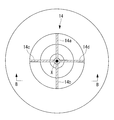
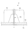
- the partition plate 14 is a plate-like member provided on the upstream side of the flow direction of the air than the intake port 11 a and having a predetermined length in the axis X direction. As shown in FIG. 2, the partition plate 14 is comprised by four partition plates 14a, 14b, 14c, and 14d. The four partition plates 14a, 14b, 14c and 14d are radially arranged about the axis X.
- the partition plate 14 is devised to function as an impact absorbing material that absorbs the impact caused by the collision of all or part of the air guide cylinder 12.
- the partition plate 14 also supports the silencer casing 15 a of the silencer 15 and also functions as a flow straightening plate for straightening the air flowing in the silencer 15.
- the cross section along the axis X is a rectangle that is long in the axis X direction.
- the other partition plates 14a, 14c, and 14d also have the same cross-sectional shape.
- the partition plate 14 is made of a metal member manufactured by rolling.
- a metal member for example, a rolled steel material which is an Fe—C based alloy containing iron as a main component and a slight amount (about 0.2%) of carbon is used.
- a rolled steel material for general structure (JIS G 3101; ASTM A 283) called SS400.
- the metal material by rolling has a composition suitable for a rolling process, and retains ductility leading to fracture after large plastic deformation.
- the metal material by casting consists of a composition suitable for a casting process, and the elongation to failure is smaller than the metal material by rolling.
- the metal material by rolling has a greater elongation to failure than the metal material by casting, that is, the ductility is high. Therefore, the rolled metal material has the property of higher fracture strength to impact than the cast metal material.
- the tensile strength at normal temperature is about 400 to 500 N / mm 2 for both ductile cast iron and SS400.
- the elongation at break is about 10% of the ductile cast iron material
- the S400 material retains 20% or more. Therefore, the SS400 material has higher ductility than the ductile cast iron material.
- the flow path 11e of the centrifugal compressor 10 is a flow path which is gradually inclined from the direction of the axis X from the intake port 11a toward the discharge port 11b. Therefore, an impact force in the radial direction and an impact force in the direction of the axis X are applied to the air guide cylinder 12.
- the impact force in the direction of the axis X is an impact force that causes the air guide cylinder 12 to fly away from the scroll portion 13. Therefore, the air guide cylinder 12 made of a metal member manufactured by casting is damaged and falls off from the mounting position. there is a possibility.
- the partition plate 14 made of a metal member by rolling retains large plastic deformation ductility until failure, and therefore absorbs kinetic energy of impact by plastic deformation when an impact load is generated. Thereby, scattering of all or part of the air guide cylinder 12 can be stopped. That is, by intentionally deforming and breaking the partition plate 14 to absorb an impact, the air guide cylinder 12 is scattered to the outside of the turbocharger 100 or an impact is given to other places to form a gap (opening). Is suppressing the problem that occurs.
- the plate thickness of the partition plate 14 of the present embodiment is in the range of 4 mm to 9 mm. Moreover, it is more preferable to set it as 5 mm or more and 7 mm or less, and it is preferable to set board thickness to 6 mm especially. If the rigidity of the partition plate 14 is too low, the impact load of all or part of the air guide cylinder 12 broken and scattered can not be sufficiently absorbed even if the partition plate 14 is greatly deformed, all or the air guide cylinder 12 A part is scattered to the outside of the turbocharger 100.
- the partition plate 14 when the rigidity of the partition plate 14 is too high, the deformation of the partition plate 14 with respect to the impact load of all or part of the scattered air guide cylinder 12 decreases. Then, the partition plate 14 can not absorb the impact load, and the impact load propagates to other places, generating a gap (opening).
- the inventors conducted experiments while changing the plate thickness of the partition plate 14, and the air guide cylinder 12 was not scattered to the outside, and a gap (opening) was not generated at other places. Since we have obtained the knowledge that the range is 9 mm or less, the plate thickness in this range is used.
- the silencer 15 shown in FIG. 1 is a device for reducing the level of noise generated in the centrifugal compressor 10.
- the silencer 15 is provided with a silencer casing 15a.
- the silencer casing 15 a defines a flow path 15 b for guiding the air flowing in from the direction shown by the arrow in FIG. 1 (the direction orthogonal to the axis X) to the inlet 11 a of the air guiding cylinder 12.
- a silencer material 15e is disposed around the flow passage 15b so as to surround the flow passage 15b. A part of the noise generated in the centrifugal compressor 10 is absorbed by the sound deadening material 15e, and the noise level is reduced.
- the silencer casing 15a accommodates the partition plate 14 inside.
- the end of the partition plate 14 is connected to the silencer casing 15a. Therefore, the partition plate 14 also functions as a support member for supporting the silencer casing 15a.
- the partition plate 14 made of a rolled steel material absorbs and restrains kinetic energy of impact by plastic deformation when impact load is generated.
- a structure for absorbing kinetic energy of impact other than the partition plate 14 will be described.
- the flange portion 13d provided at the end of the scroll casing 13b on the silencer 15 side and the flange portion 15c provided at the end of the silencer casing 15a on the scroll casing 13b side are shown in FIG.
- the fastening bolt 40 (first fastening bolt) is fastened at the fastening position (first fastening position) shown.
- a plurality of fastening positions are provided at regular intervals in the circumferential direction around the axis X.
- the flange portion 13 d and the flange portion 15 c are fastened by the fastening bolt 40 at the plurality of fastening positions.
- the fastening bolt 40 it is preferable to use chromium molybdenum steel having a carbon content of 0.33 to 0.38%, which is called SCM435.
- the SCM 435 is excellent in that it has high strength and a large amount of elongation until breakage when a tensile load is applied.
- the flange portion 15 c is provided with a fastening hole 15 d extending along the axis X.
- the fastening hole 13e extended along the axis line X is provided in the flange part 13d. Internal threads are formed on the inner peripheral surfaces of these fastening holes 15d and 13e.
- a male screw is formed on the entire surface from the vicinity of the boundary between the head 40a and the shaft 40b to the vicinity of the tip of the shaft 40b. ing.
- a tensile load is generated on the fastening bolt 40 by equalizing the deformation at each location on the outer peripheral surface of the shaft portion 40b, and even if plastic deformation is performed until the amount of elongation is large, stress is locally concentrated in the bolt 40 It is preferable because it does not break up to a large elongation because it is difficult.
- the flange portion 13 d and the flange portion 15 c are cylindrical in shape and have a predetermined length and a cylindrical shape having an inner diameter d 1 smaller than the diameter d 2 of the head portion 40 a of the fastening bolt 40. It is fastened in the state inserted in the axial part 40b. In this state, the external thread formed on the shaft portion 40b of the fastening bolt 40 and the internal thread formed on the inner circumferential surfaces of the fastening holes 15d and 13e are in a meshed state.
- the spacer 50 is made of a metal member manufactured by rolling.
- a metal member for example, a rolled steel material which is an Fe—C based alloy containing iron as a main component and a slight amount (about 0.2%) of carbon is used.
- various materials can be used if it is a rolled steel material, it is preferable to use a rolled steel material for general structure (JIS G 3101; ASTM A 283) called SS400. Since the rolled metal material retains ductility leading to failure after large plastic deformation, it has characteristics of higher fracture strength to impact than cast metal.
- the air guide cylinder 12 and the scroll casing 13 b are fastened by a fastening bolt 42 inserted into a through hole provided in the flange portion 12 a of the air guide cylinder 12.
- a fastening bolt 42 inserted into a through hole provided in the flange portion 12 a of the air guide cylinder 12.
- a plurality of fastening positions are provided at regular intervals in the circumferential direction around the axis X.
- the air guide cylinder 12 and the scroll casing 13 b are fastened by the fastening bolt 42 at the fastening positions of the plurality of places.
- the reason why the spacer 50 is inserted into the shaft portion 40b of the fastening bolt 40 as shown in FIG. 4 is to lengthen the length of the fastening bolt 40 in the direction of the axis X to secure a large amount of extension. is there.
- the predetermined length of the spacer 50 is at least longer than the diameter of the shaft portion 40b of the fastening bolt 40, and the length is set so as not to hinder the fastening operation.
- the reason for providing the spacer 50 is to make the spacer 50 made of rolled steel having ductility absorb the kinetic energy of impact. Due to an impact acting on the fastening position of the fastening bolt 40 and the flange portion 15 c, the length of the spacer 50 disposed between the head 40 a of the fastening bolt 40 and the flange portion 15 c shrinks in the direction of the axis X. Since the spacer 50 made of rolled steel retains ductility leading to fracture after large plastic deformation, it can absorb the kinetic energy due to the above-mentioned impact by contracting along the direction of the axis X.
- the bearing stand 20 of the present embodiment includes a flange portion 20 a that supports the scroll portion 13 and a bearing portion 20 b that supports the rotor shaft 30.
- the fastening bolt 41 (second fastening bolt) is fastened at the fastening position (second fastening position) shown in FIG.
- the fastening bolt 41 it is preferable to use a chromium molybdenum steel having a carbon content of 0.33 to 0.38%, which is called SCM435.
- SCM 435 is excellent in that it has high strength and a large amount of elongation.
- the flange portion 13 f is provided with a fastening hole 13 g extending along the axis X. Moreover, the fastening hole 20c extended along the axis line X is provided in the flange part 20a. Internal threads are formed on the inner peripheral surfaces of these fastening holes 13g and 20c. On the other hand, on the outer peripheral surface of the shaft portion 41b of the fastening bolt 41 extending along the axis X, a male screw is formed on the entire surface from the head portion 41a to the tip portion.
- the flange portion 13 f and the flange portion 20 a insert the cylindrical spacer 51 (second spacer member) having an inner diameter d 3 smaller than the diameter d 4 of the head portion 41 a of the fastening bolt 41 into the shaft portion 41 b of the fastening bolt 41 It is concluded in the state. In this state, the external thread formed on the shaft portion 41b of the fastening bolt 41 and the internal thread formed on the inner peripheral surfaces of the fastening holes 13g and 20c are engaged with each other.
- the spacer 51 is made of a metal member manufactured by rolling.
- a metal member for example, a rolled steel material which is an Fe—C based alloy containing iron as a main component and a slight amount (about 0.2%) of carbon is used.
- various materials can be used if it is a rolled steel material, it is preferable to use a rolled steel material for general structure (JIS G 3101; ASTM A 283) called SS400. Since the rolled metal material retains ductility leading to failure after large plastic deformation, it has characteristics of higher fracture strength to impact than cast metal.
- the reason why the spacer 51 is inserted into the shaft portion 41b of the fastening bolt 41 as shown in FIG. 5 is to lengthen the length of the fastening bolt 41 in the direction of the axis X to secure a large amount of extension. is there.
- By increasing the amount of extension it is possible to prevent the fastening bolt 41 from breaking, and by extension of the fastening bolt 41, all or a part of the air guiding cylinder 12 drops out from the mounting position and scatters and collides Can absorb the kinetic energy of impact.
- the reason for providing the spacer 51 is to make the spacer 51 made of rolled steel having ductility absorb the kinetic energy of impact. Due to an impact acting on the fastening position of the fastening bolt 41 and the flange portion 13f, the length of the spacer 51 disposed between the head portion 41a of the fastening bolt 41 and the flange portion 13f shrinks in the direction of the axis X. Since the spacer 51 made of rolled steel retains ductility leading to fracture after large plastic deformation, it can absorb the kinetic energy due to the above-described impact by contracting along the direction of the axis X.
- FIG. 6 is a view of the outer peripheral edge of the flange portion 13f of the scroll casing 13b and the flange portion 20a from the P direction shown in FIG.
- a plurality of clamp members 60 are attached between a plurality of fastening positions (second fastening positions) by the fastening bolts 41.
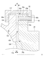
- the clamp member 60 has a recess 60a surrounding the outer peripheral edge of the flange portion 20a and the outer peripheral edge of the flange portion 13f of the scroll casing 13b from the outer peripheral side.
- the clamp member 60 has a through hole 60b that opens in the recess 60a and extends along the axis X direction.
- the flange portion 20 a has a fastening hole 20 d extending in the direction of the axis X. Although only one fastening hole 20 d is shown in FIG. 7, the fastening holes 20 d are provided at a plurality of locations at equal intervals along the circumferential direction around the axis X. An internal thread is formed on the inner peripheral surface of the fastening hole 20d. On the other hand, a male screw is formed on the outer peripheral surface of the shaft portion of the fastening bolt 43 (third fastening bolt) inserted into the through hole 60b and the fastening hole 20d. The flange portion 20a and the clamp member 60 are fastened by the engagement of the male screw of the fastening bolt 43 and the female screw of the fastening hole 20d.
- a predetermined gap 60c is provided between the end face 13i in the axial line X direction of the scroll casing 13b and the end face 60e in the axial line X direction of the recess 60a. .
- the width along the axis X of the gap 60c is d5.
- the flange portion 20a connects the contact surface 20e in contact with the scroll casing 13b, the end surface 20f forming the flow passage 13h (second flow passage) through which the compressed air flows, and the step connecting the contact surface 20e and the end surface 20f And a unit 20g.
- the end face 20f is disposed closer to the flow path 13h than the contact surface 20e.
- the width d6 in the direction of the axis X of the step 20g is wider than the width d5 of the gap 60c.
- the reason why the predetermined gap 60c is provided is that the fastening bolt 41 is broken because the impact in the direction of the axis X due to the scattering of all or part of the impeller 11 is broken and the scroll casing 13b
- the clamp member 60 absorbs the impact of the separated scroll casing 13b.
- the fastening force in the vicinity of the clamp member 60 is increased, and the fastening bolt 41 becomes difficult to break.
- a load is applied to another portion (for example, the scroll casing 13b), and there is a possibility that the portion to which the load is applied may be broken.
- the width d6 in the direction of the axis X of the step 20g is wider than the width d5 of the gap 60d. Therefore, the problem that a gap (opening) such that the gap 60d communicates with the flow path 13h and the damaged member passes is prevented.
- the gap 60c is intentionally provided between the end face 13i in the direction of the axis X of the scroll casing 13b and the end face 60e in the direction of the axis X of the recess 60a. It is preventing.
- the clamp member 60 absorbs an impact caused by the scroll casing 13 b moving away from the bearing stand 20.
- the manufacturing method of the centrifugal compressor 10 of this embodiment manufactures the centrifugal compressor 10 by the following processes.
- the impeller 11 which compresses the air flowing in from the inlet 11 a and discharges it from the outlet 11 b is attached to the rotor shaft 30.
- the air guide cylinder 12 is attached so as to accommodate the impeller 11, and the air flowing from the intake port 11a along the axis X direction of the rotor shaft 30 is guided in the direction inclined from the axis X direction.
- a flow path leading to the discharge port 11 b is formed.
- the scroll portion 13 into which the compressed air discharged from the discharge port 11 b flows is disposed on the outer peripheral side in the radial direction orthogonal to the axis X direction with respect to the air guide cylinder 12.
- a plurality of partition plates 14 having a plate thickness of 4 mm or more and 9 mm or less are provided upstream of the intake port 11 a in the air flow direction and have a predetermined length in the axis X direction. Arrange radially around X.
- the centrifugal compressor 10 of the present embodiment is manufactured by the above steps.
- centrifugal compressor 10 provided in the turbocharger 100 of the present embodiment described above will be described. According to the centrifugal compressor 10 provided in the turbocharger 100 of the present embodiment, when all or part of the impeller 11 breaks or drops off, all or part of the impeller 11 scatters in the radial direction, and It collides with the guide cylinder 12.
- the air guide cylinder 12 forms a flow passage 11 e which guides the air flowing in from the intake port 11 a along the axis X direction of the rotor shaft 30 in a direction inclined from the axis X direction and guides the air to the discharge port 11 b.
- a radial impact is applied to the air guide cylinder 12.
- an impact in the direction of the axis X is applied to the air guiding cylinder 12. Since the impact in the direction of the axis X is an impact that scatters all or part of the air guide cylinder 12 in the direction away from the scroll portion 13, all or part of the air guide cylinder 12 may fall out of the mounting position .
- a plurality of partition plates 14 having a predetermined length in the axis X direction are arranged radially about the axis X on the upstream side of the flow direction of air than the intake port 11a. It is done. Therefore, all or part of the scattered impeller 11 or all or part of the air guide cylinder 12 scattered in the direction away from the scroll portion 13 due to the impact of the impeller 11 collides with the plurality of partition plates 14 .
- the plurality of partition plates 14 are rolled steel materials having a plate thickness of 4 mm or more and 9 mm or less. Therefore, when all or a part of the air guide cylinder 12 collides, it plastically deforms appropriately and absorbs energy due to the collision. Thereby, a gap is generated in a part of the centrifugal compressor 10 by scattering of all or a part of the air guide cylinder 12, and a defect that all or a part of the impeller 11 scatters to the outside from the gap is suppressed. Can.
- the centrifugal compressor 10 of the present embodiment when all or part of the air guide cylinder 12 scattered in the direction away from the scroll portion 13 collides with the silencer casing 15a accommodating the partition plate 14, the silencer casing 15a is used as the scroll casing Impact is applied in the direction away from the This impact is absorbed by contraction of the spacer 50 disposed between the head 40 a of the fastening bolt 40 and the silencer casing 15 a.
- the problem of breakage of the fastening bolt 40 is suppressed by absorbing the impact in the axial direction using the spacer 50 that is fastened in a state of being inserted into the fastening bolt 40. Therefore, a gap is generated in a part of the centrifugal compressor 10 due to the scattering of all or a part of the air guide cylinder 12, and it is possible to suppress the problem that the impeller 11 is scattered all or part to the outside through the gap.
- the fastening bolt 40 includes an external thread formed on the outer peripheral surface of the shaft portion 40 b from the head portion 40 a to the tip end portion.
- the centrifugal compressor 10 of the present embodiment when all or part of the air guide cylinder 12 scattered in the direction away from the scroll portion 13 collides with the silencer casing 15a accommodating the partition plate 14, the scroll casing 13b is supported by the bearing base An impact in the direction of pulling away from the flange portion 20a of 20 is applied. This impact is absorbed by contraction of the spacer 51 disposed between the head 41 a of the fastening bolt 41 and the scroll casing 14 b.
- the spacer 51 that is fastened in a state of being inserted into the fastening bolt 41 a problem in which the fastening bolt 41 is broken by absorbing an impact in the direction of the axis X is suppressed. Therefore, a gap is generated in a part of the centrifugal compressor 10 due to the scattering of all or a part of the air guide cylinder 12, and it is possible to suppress the problem that the impeller 11 is scattered all or part to the outside through the gap.
- the fastening bolt 41 includes an external thread formed on the outer peripheral surface of the shaft portion 40b from the head portion 41a to the tip end portion.
- the centrifugal compressor 10 has a recess 60a that surrounds the outer peripheral edge of the flange portion 20a and the outer peripheral edge of the scroll casing 13b from the outer peripheral side, and opens in the recess 60a and extends along the axis X direction.
- a plurality of clamp members 60 having through holes 60 b are provided.
- the flange portion 20a has a plurality of fastening holes 20d extending in the direction of the axis X in the circumferential direction around the axis X.
- the flange portion 20a and the clamp member 60 are fastened by the fastening bolt 43 inserted into the through hole 60b and the fastening hole 20d.
- a predetermined gap 60c is provided between the end face 13i in the direction of the axis X of the scroll casing 13b and the end face 60e in the direction of the axis X of the recess 60a.
- the flange portion 20a is fastened by the clamp member 60 and the fastening bolt 43, and is predetermined between the end face 13i in the axis X direction of the scroll casing 13b and the end face 60e in the axis X direction of the recess 60a.
- a gap 60c is provided.
- the flange portion 20a forms a contact surface 20e in contact with the scroll casing 13b, and an end surface 20f of the flange portion 20a which is disposed on the flow passage 13h side with respect to the contact surface 20e, while forming a flow passage 13h through which the compressed air flows.
- the plurality of fastening bolts 41 are broken and the flange portion 20a of the bearing stand 20 and the scroll casing 13b are separated, and the end surface 13i in the direction of the axis X of the scroll casing 13b is the axis X in the recess 60a.
- the opening between the flange 20a and the scroll casing 13b is suppressed by the presence of the step 20g.
- the width d6 in the direction of the axis X of the step 20g is larger than the width d5 of the predetermined gap 60d, no communication gap is generated, and the opening can be more reliably suppressed.
- the rotor shaft 30 to which the impeller 11 of the centrifugal compressor 10 is connected is rotated about the axis X by a turbine (not shown) rotated by the exhaust gas discharged from the marine diesel engine.
- a turbine not shown
- the rotor shaft 30 may be rotated by another power source such as a motor connected to the rotor shaft 30.
- the partition plate 14 radially arranges four sheets at intervals of 90 degrees centering on the axis line X, another aspect may be sufficient.
- an arbitrary number of sheets may be disposed, such as an aspect in which six sheets are radially disposed at an interval of 60 degrees around the axis X, or an aspect in which eight sheets are disposed at an interval of 45 degrees.
- the clamp member 60 is fastened to the flange portion 20a of the bearing stand 20, but may be in another mode.
- the clamp member 60 may be fastened to the flange portion 13e of the scroll casing 13b.
- the flange portion 13e of the scroll casing 13b has a plurality of fastening holes extending in the direction of the axis X in the circumferential direction around the axis X. Then, by fastening the fastening bolts 43 in the plurality of fastening holes, the clamp member 60 is fastened to the flange portion 13e of the scroll casing 13b.
- the gap 60c described above is provided between the end face in the axial line X direction of the flange portion 20a of the bearing stand 20 and the end face in the axial line X direction of the recess of the clamp member 60.
Landscapes
- Engineering & Computer Science (AREA)
- Mechanical Engineering (AREA)
- General Engineering & Computer Science (AREA)
- Structures Of Non-Positive Displacement Pumps (AREA)
Abstract
Description
しかしながら、羽根車の全部または一部が破断あるいは脱落して案内筒に衝突する場合、その衝撃荷重が大きいために案内筒が破損し、羽根車の全部または一部とともに案内筒の全部または一部が外部に飛散する可能性がある。また、案内筒が破損しない場合でも、案内筒の全体またはその一部が取付位置から脱落し、ロータ軸の軸線に沿ってスクロール部から離れる方向に飛散する可能性がある。この場合、案内筒の全部または一部が飛散することによって遠心圧縮機の一部に隙間(口開き)が生じ、その隙間から羽根車の破損した一部が外部に飛散する可能性がある。
また、本発明は、前述した遠心圧縮機を備えた過給機、および前述した遠心圧縮機の製造方法を提供することを目的とする。
本発明の第1態様に係る遠心圧縮機は、ロータ軸に取り付けられるとともに取込口から流入する流体を圧縮して吐出口から吐出する羽根車と、該羽根車を収容する案内筒と、該案内筒よりも外周側に配置されるとともに前記吐出口から吐出された圧縮流体が流入するスクロール部と、前記取込口よりも流体の流通方向の上流側に設けられるとともに前記ロータ軸の軸線方向に所定の長さを有する複数の仕切板と、前記複数の仕切板を収容するサイレンサとを備え、前記複数の仕切板は、前記軸線を中心として放射状に配置されるとともに該仕切板の板厚が4mm以上かつ9mm以下の圧延鋼材であることを特徴とする。
このようにすることで、頭部から先端部に至る軸部の外周面の各箇所での変形を均一化することで衝撃のエネルギー吸収を大きくした第1締結ボルトを用いて、前述した不具合を抑制することができる。
このようにすることで、頭部から先端部に至る軸部の外周面の各箇所での変形を均一化することで衝撃のエネルギー吸収を大きくした第2締結ボルトを用いて、前述した不具合を抑制することができる。
更に、段部の軸線方向の幅を、所定の隙間の幅よりも広くすることによって、口開きをより確実に抑制することができる。
本発明に係る過給機によれば、遠心圧縮機が備える案内筒が飛散することによって遠心圧縮機の一部に隙間が生じ、その隙間から羽根車の一部が外部に飛散する不具合を抑制することができる。
また、本発明によれば、前述した遠心圧縮機を備えた過給機、および前述した遠心圧縮機の製造方法を提供することができる。
本実施形態の過給機100は、船舶に用いられる舶用ディーゼル機関(内燃機関)に供給する空気(気体)を大気圧以上に高めて、舶用ディーゼル機関の燃焼効率を高める装置である。
図1に示すように、本実施形態の過給機100は、遠心圧縮機10と、タービン(図示略)と、軸受台20とを備えている。遠心圧縮機10とタービンとは、それぞれロータ軸30に連結されている。ロータ軸30は、軸受台20によって軸線X回りに回転可能な状態で支持されている。
図1に示すように、羽根車11は、軸線Xに沿って延びるロータ軸30に取り付けられており、ロータ軸30が軸線X回りに回転するのに伴って、軸線X回りに回転する。羽根車11は、軸線X回りに回転することにより、取込口11aから流入する空気を圧縮して吐出口11bから吐出する。
発明者らは、仕切板14の板厚を変えながら実験を行い、空気案内筒12が外部へ飛散せず、かつ、他の箇所で隙間(口開き)が発生しない板厚として、4mm以上かつ9mm以下の範囲という知見を得たため、この範囲の板厚としている。
前述したように空気案内筒12の全部または一部が取付位置から脱落して飛散すると、空気案内筒12の全部または一部が仕切板14に衝突する。前述では圧延鋼材からなる仕切板14は、衝撃荷重が発生した際に衝撃の運動エネルギーを塑性変形することで吸収して制止させることを説明した。以降では仕切板14以外で衝撃の運動エネルギーを吸収する構造について説明する。
締結ボルト40として、SCM435と呼ばれる炭素量0.33~0.38%のクロムモリブデン鋼を用いるのが好ましい。SCM435は、強度が高く、引張荷重が印加された際に破断に至るまでの伸長量が大きい点で優れている。
圧延による金属材は、大きな塑性変形の後に破壊に至る延性を保有するので、鋳造による金属よりも衝撃に対する破壊強度が高い特性を保有する。
前述したように空気案内筒12の全部または一部が取付位置から脱落して飛散すると、空気案内筒12の全部または一部が仕切板14に衝突する。この衝突によってサイレンサケーシング15aにスクロールケーシング13bから離間する方向の衝撃が加わる。この衝撃は、締結ボルト40とフランジ部15cとフランジ部13dの締結位置に作用する。
図1に示すように、本実施形態の軸受台20は、スクロール部13を支持するフランジ部20aと、ロータ軸30を支持する軸受部20bとを備えている。
締結ボルト41として、SCM435と呼ばれる炭素量0.33~0.38%のクロムモリブデン鋼を用いるのが好ましい。SCM435は、強度が高く、伸長量が大きい点で優れている。
圧延による金属材は、大きな塑性変形の後に破壊に至る延性を保有するので、鋳造による金属よりも衝撃に対する破壊強度が高い特性を保有する。
図6に示すように、軸線X回りの周方向において、締結ボルト41による複数の締結位置(第2締結位置)の間に、複数のクランプ部材60が取り付けられている。
段部20gの軸線X方向の幅d6は、隙間60cの幅d5よりも広くなっている。
図8に示す状態となると、スクロールケーシング13bの軸線X方向の端面13iと凹所60aの軸線X方向の端面60eとが接触した状態となる。この状態において、接触面20eの部分には、軸線X方向の幅がd5の隙間60dが形成される。この隙間60dが流路13hと連通して隙間(口開き)が生じてしまうと、流路13hからブレード11dの破損した一部等が外部に飛散してしまう可能性がある。
本実施形態においては、図8に示すように、段部20gの軸線X方向の幅d6が隙間60dの幅d5よりも広くなっている。そのため、隙間60dが流路13hと連通して破損した部材が通過するような隙間(口開き)が生じてしまう不具合が防止される。
本実施形態の遠心圧縮機10の製造方法は、以下の工程によって遠心圧縮機10を製造する。
第1工程において、取込口11aから流入する空気を圧縮して吐出口11bから吐出する羽根車11をロータ軸30に取り付ける。
第2工程において、羽根車11を収容するように空気案内筒12を取り付けてロータ軸30の軸線X方向に沿って取込口11aから流入する空気を軸線X方向から傾斜した方向に案内して吐出口11bへ導く流路を形成する。
第4工程において、板厚が4mm以上かつ9mm以下の複数の仕切板14を、取込口11aよりも空気の流通方向の上流側に設けるとともに軸線X方向に所定の長さを有するように軸線Xを中心として放射状に配置する。
以上の工程により、本実施形態の遠心圧縮機10が製造される。
本実施形態の過給機100が備える遠心圧縮機10によれば、羽根車11の全部または一部が破断あるいは脱落する場合、羽根車11の全部または一部が径方向に飛散して、空気案内筒12に衝突する。
以上の説明において、遠心圧縮機10が備える羽根車11が連結されるロータ軸30は、舶用ディーゼル機関から排出される排気ガスにより回転するタービン(図示略)によって軸線X回りに回転するものであったが、他の態様であってもよい。例えば、ロータ軸30は、ロータ軸30に連結されたモータ等の他の動力源によって回転するものであってもよい。
11 羽根車
11a 取込口
11b 吐出口
11d ブレード
11e 流路
12 空気案内筒(案内筒)
13 スクロール部
13b スクロールケーシング
13d フランジ部
13f フランジ部
13h 流路(第2流路)
13i 端面
14 仕切板
15 サイレンサ
15a サイレンサケーシング
15b 流路(第1流路)
15c フランジ部
20 軸受台
20a フランジ部
20e 接触面
20f 端面
20g 段部
30 ロータ軸
40 締結ボルト(第1締結ボルト)
41 締結ボルト(第2締結ボルト;フランジ部締結ボルト)
43 締結ボルト(第3締結ボルト;クランプ部材締結ボルト)
50 スペーサ(第1スペーサ部材)
51 スペーサ(第2スペーサ部材)
60 クランプ部材
60a 凹所
60b 貫通穴
60c 隙間
60d 隙間
60e 端面
100 過給機
Claims (10)
- ロータ軸に取り付けられるとともに取込口から流入する流体を圧縮して吐出口から吐出する羽根車と、
該羽根車を収容する案内筒と、
該案内筒よりも外周側に配置されるとともに前記吐出口から吐出された圧縮流体が流入するスクロール部と、
前記取込口よりも流体の流通方向の上流側に設けられるとともに前記ロータ軸の軸線方向に所定の長さを有する複数の仕切板と、
前記複数の仕切板を収容するサイレンサケーシングを有するサイレンサとを備え、
前記複数の仕切板は、前記軸線を中心として放射状に配置されるとともに該仕切板の板厚が4mm以上かつ9mm以下の圧延鋼材であることを特徴とする遠心圧縮機。 - 前記スクロール部が、前記吐出口から吐出された圧縮流体が流入する渦形室を形成するスクロールケーシングを有し、
該スクロールケーシングと前記サイレンサケーシングとが、前記軸線回りの周方向の複数の第1締結位置において前記軸線方向に延びる複数の第1締結ボルトによって締結されており、
前記スクロールケーシングと前記サイレンサケーシングとは、前記第1締結ボルトの頭部の直径よりも内径の小さい円筒状の第1スペーサ部材を、前記第1締結ボルトの軸部に挿入した状態で締結されることを特徴とする請求項1に記載の遠心圧縮機。 - 前記第1締結ボルトは、前記頭部から先端部に至る前記軸部の外周面に形成された雄ねじを備えることを特徴とする請求項2に記載の遠心圧縮機。
- 前記ロータ軸を支持する軸受部と、前記スクロール部を支持するフランジ部とを有する軸受台を備え、
該フランジ部と前記スクロールケーシングとが、前記軸線回りの複数の第2締結位置において前記軸線方向に延びる複数の第2締結ボルトによって締結されており、
前記フランジ部と前記スクロールケーシングとは、前記第2締結ボルトの頭部の直径よりも内径の小さい円筒状の第2スペーサ部材を、前記第2締結ボルトの軸部に挿入した状態で締結されることを特徴とする請求項2または請求項3に記載の遠心圧縮機。 - 前記第2締結ボルトは、前記頭部から先端部に至る前記軸部の外周面に形成された雄ねじを備えることを特徴とする請求項4に記載の遠心圧縮機。
- ロータ軸に取り付けられるとともに取込口から流入する流体を圧縮して吐出口から吐出する羽根車と、
該羽根車を収容する案内筒と、
該案内筒よりも外周側に配置されるとともに前記吐出口から吐出された圧縮流体が流入する渦形室を形成するスクロールケーシングを有するスクロール部と、
前記ロータ軸を支持する軸受部および前記スクロール部を支持するフランジ部を有する軸受台と、
前記フランジ部と前記スクロールケーシングとを、前記ロータ軸の軸線回りの複数の締結位置において前記軸線方向に延びる複数のフランジ部締結ボルトと、
前記フランジ部の外周縁部と前記スクロールケーシングの外周縁部とを外周側から取り囲む凹所と、該凹所に開口するとともに前記軸線方向に沿って延びる貫通穴とを有するクランプ部材を複数備え、
前記フランジ部または前記スクロールケーシングのいずれか一方が、前記軸線方向に延びる締結穴を前記軸線回りの周方向に複数有しており、
前記フランジ部または前記スクロールケーシングのいずれか一方と前記クランプ部材とが、前記貫通穴および前記締結穴に挿入されるクランプ部材締結ボルトによって締結されており、
前記フランジ部または前記スクロールケーシングのいずれか他方の前記軸線方向の端面と、前記凹所の前記軸線方向の端面との間に所定の隙間が設けられていることを特徴とする遠心圧縮機。 - 前記フランジ部は、前記締結穴を有するとともに前記クランプ部材と前記クランプ部材締結ボルトによって締結されており、
前記スクロールケーシングの前記軸線方向の端面と、前記凹所の前記軸線方向の端面との間に所定の隙間が設けられており、
前記フランジ部は、前記スクロールケーシングと接触する接触面と、前記圧縮流体が流通する第2流路を形成するとともに前記接触面よりも前記第2流路側に配置される前記フランジ部の端面とを接続する段部を有することを特徴とする請求項6に記載の遠心圧縮機。 - 前記段部の前記軸線方向の幅が、前記所定の隙間の幅よりも広いことを特徴とする請求項7に記載の遠心圧縮機。
- 請求項1から8のいずれか1項に記載の遠心圧縮機と、
内燃機関から排出された排気ガスにより前記軸線回りに回転するとともに前記ロータ軸に連結されるタービンと、を備えることを特徴とする過給機。 - 取込口から流入する流体を圧縮して吐出口から吐出する羽根車をロータ軸に取り付ける工程と、
前記羽根車を収容するように案内筒を取り付けて前記取込口から流入する流体を前記吐出口へ導く流路を形成する工程と、
前記吐出口から吐出された圧縮流体が流入するスクロール部を、前記案内筒よりも前記軸線方向に直交する径方向の外周側に配置する工程と、
板厚が4mm以上かつ9mm以下の複数の仕切板を、前記取込口よりも流体の流通方向の上流側に設けるとともに前記軸線方向に所定の長さを有するように前記軸線を中心として放射状に配置する工程と、を備えることを特徴とする遠心圧縮機の製造方法。
Priority Applications (4)
| Application Number | Priority Date | Filing Date | Title |
|---|---|---|---|
| KR1020167026159A KR101918377B1 (ko) | 2014-03-31 | 2015-02-24 | 원심 압축기, 과급기 및 원심 압축기의 제조 방법 |
| EP18185764.0A EP3412916B1 (en) | 2014-03-31 | 2015-02-24 | Centrifugal compressor, supercharger, and method for manufacturing centrifugal compressor |
| EP15774147.1A EP3128184B1 (en) | 2014-03-31 | 2015-02-24 | Centrifugal compressor, supercharger, and method for manufacturing centrifugal compressor |
| CN201580013773.6A CN106104006B (zh) | 2014-03-31 | 2015-02-24 | 离心压缩机、增压器、离心压缩机的制造方法及消音器 |
Applications Claiming Priority (2)
| Application Number | Priority Date | Filing Date | Title |
|---|---|---|---|
| JP2014074071A JP6391970B2 (ja) | 2014-03-31 | 2014-03-31 | 遠心圧縮機、過給機、および遠心圧縮機の製造方法、並びにサイレンサ |
| JP2014-074071 | 2014-03-31 |
Publications (1)
| Publication Number | Publication Date |
|---|---|
| WO2015151653A1 true WO2015151653A1 (ja) | 2015-10-08 |
Family
ID=54239989
Family Applications (1)
| Application Number | Title | Priority Date | Filing Date |
|---|---|---|---|
| PCT/JP2015/055240 Ceased WO2015151653A1 (ja) | 2014-03-31 | 2015-02-24 | 遠心圧縮機、過給機、および遠心圧縮機の製造方法 |
Country Status (5)
| Country | Link |
|---|---|
| EP (2) | EP3412916B1 (ja) |
| JP (1) | JP6391970B2 (ja) |
| KR (1) | KR101918377B1 (ja) |
| CN (2) | CN108799204B (ja) |
| WO (1) | WO2015151653A1 (ja) |
Cited By (5)
| Publication number | Priority date | Publication date | Assignee | Title |
|---|---|---|---|---|
| EP3324053A4 (en) * | 2016-03-30 | 2018-09-19 | Mitsubishi Heavy Industries, Ltd. | Compression device and supercharger |
| WO2020021744A1 (ja) * | 2018-07-24 | 2020-01-30 | 三菱重工業株式会社 | 回転機械及び過給機 |
| JP2022064333A (ja) * | 2018-03-30 | 2022-04-25 | 株式会社村田製作所 | Cpap装置 |
| CN114514367A (zh) * | 2019-07-29 | 2022-05-17 | 康明斯有限公司 | 轴承座和制造的方法 |
| CN115698480A (zh) * | 2020-06-04 | 2023-02-03 | 三菱重工船用机械株式会社 | 涡轮壳体和增压器 |
Families Citing this family (17)
| Publication number | Priority date | Publication date | Assignee | Title |
|---|---|---|---|---|
| DE102015014550A1 (de) * | 2015-11-11 | 2017-05-11 | Man Diesel & Turbo Se | Ansaugsystem für einen Abgasturbolader und Abgasturbolader |
| DE102016111081B4 (de) * | 2016-06-17 | 2024-08-01 | Man Energy Solutions Se | Strömungsmaschine |
| JP6847683B2 (ja) * | 2017-01-31 | 2021-03-24 | 三菱重工業株式会社 | 遠心圧縮機および過給機 |
| WO2019087970A1 (ja) | 2017-11-01 | 2019-05-09 | 株式会社Ihi | 遠心圧縮機 |
| DE112018005188T5 (de) | 2017-11-01 | 2020-06-25 | Ihi Corporation | Zentrifugalverdichter |
| DE112018005240T5 (de) | 2017-11-01 | 2020-07-02 | Ihi Corporation | Zentrifugalverdichter |
| US11067098B2 (en) | 2018-02-02 | 2021-07-20 | Carrier Corporation | Silencer for a centrifugal compressor assembly |
| JP2019203446A (ja) * | 2018-05-23 | 2019-11-28 | 株式会社オティックス | ターボチャージャ用のコンプレッサハウジング及びその製造方法 |
| JP7393095B2 (ja) * | 2018-06-07 | 2023-12-06 | トヨタ自動車株式会社 | 気体圧縮装置 |
| WO2020179985A1 (ko) * | 2019-03-06 | 2020-09-10 | (주)플로닉스 | 펌프 케이싱 및 이를 포함하는 마그넷 펌프 |
| US11859641B2 (en) * | 2019-11-27 | 2024-01-02 | James E. Petersen, Jr. | Noise abatement for air blowers |
| JP7562357B2 (ja) * | 2020-09-30 | 2024-10-07 | 三菱重工マリンマシナリ株式会社 | 回転機械 |
| US11519423B1 (en) * | 2021-11-11 | 2022-12-06 | Progress Rail Locomotive Inc. | Compressor joint |
| WO2024150387A1 (ja) * | 2023-01-13 | 2024-07-18 | 三菱重工エンジン&ターボチャージャ株式会社 | ターボチャージャ用ハウジング、及びターボチャージャ |
| CN117823463B (zh) * | 2023-12-08 | 2024-07-05 | 南京磁谷科技股份有限公司 | 高速离心式压缩机进气室结构、离心式压缩机及进气方法 |
| US20250237154A1 (en) * | 2024-01-23 | 2025-07-24 | Pratt & Whitney Canada Corp. | Impeller containment system |
| CN120759777B (zh) * | 2025-09-11 | 2025-11-18 | 潍坊学院 | 离心压气机装置 |
Citations (3)
| Publication number | Priority date | Publication date | Assignee | Title |
|---|---|---|---|---|
| JPS6413299U (ja) * | 1987-07-15 | 1989-01-24 | ||
| US20010016161A1 (en) * | 2000-01-21 | 2001-08-23 | Man Roland Druckmaschinen Ag | Turbocharger |
| JP2010127240A (ja) * | 2008-11-28 | 2010-06-10 | Mitsubishi Heavy Ind Ltd | 羽根車の取付構造 |
Family Cites Families (15)
| Publication number | Priority date | Publication date | Assignee | Title |
|---|---|---|---|---|
| US3635580A (en) * | 1970-02-26 | 1972-01-18 | Westinghouse Electric Corp | Centrifugal refrigerant gas compressor capacity control |
| US4181466A (en) * | 1977-03-17 | 1980-01-01 | Wallace Murray Corp. | Centrifugal compressor and cover |
| JP4359798B2 (ja) | 1999-11-05 | 2009-11-04 | 株式会社Ihi | 排気タービン過給機 |
| DE10050931C5 (de) * | 2000-10-13 | 2007-03-29 | Man Diesel Se | Turbomaschine mit radial durchströmten Laufrad |
| DE10107807C1 (de) * | 2001-02-20 | 2002-07-25 | Man B & W Diesel Ag | Strömungsmaschine mit radial durchströmtem Verdichterrad |
| CN100395487C (zh) * | 2003-07-31 | 2008-06-18 | 松下电器产业株式会社 | 空调机 |
| EP1860284A1 (de) * | 2006-05-23 | 2007-11-28 | ABB Turbo Systems AG | Gehäuseverbindung |
| WO2008023033A1 (de) * | 2006-08-24 | 2008-02-28 | Abb Turbo Systems Ag | Befestigung filterschalldämpfer |
| JP4648347B2 (ja) * | 2007-02-23 | 2011-03-09 | 三菱重工業株式会社 | ハイブリッド排気タービン過給機 |
| US8215451B2 (en) * | 2008-07-17 | 2012-07-10 | Nagoya Oilchemical Co., Ltd. | Impact and sound absorbing material and sound absorbing structure |
| JP5230590B2 (ja) * | 2009-12-07 | 2013-07-10 | 三菱重工業株式会社 | 排気タービン過給機の排気入口ケーシング |
| US20110305554A1 (en) * | 2010-06-14 | 2011-12-15 | Honeywell International Inc. | Light weight vaneless compressor containment design |
| DE102010038631B4 (de) * | 2010-07-29 | 2017-07-06 | Man Diesel & Turbo Se | Turboverdichter für eine Brennkraftmaschine |
| JP6008495B2 (ja) * | 2011-12-16 | 2016-10-19 | 三菱重工業株式会社 | 排気タービン過給機 |
| CN202483956U (zh) * | 2012-01-05 | 2012-10-10 | 黄晓东 | 一种离心式冷却水泵 |
-
2014
- 2014-03-31 JP JP2014074071A patent/JP6391970B2/ja active Active
-
2015
- 2015-02-24 CN CN201810697793.5A patent/CN108799204B/zh active Active
- 2015-02-24 KR KR1020167026159A patent/KR101918377B1/ko active Active
- 2015-02-24 EP EP18185764.0A patent/EP3412916B1/en active Active
- 2015-02-24 CN CN201580013773.6A patent/CN106104006B/zh active Active
- 2015-02-24 WO PCT/JP2015/055240 patent/WO2015151653A1/ja not_active Ceased
- 2015-02-24 EP EP15774147.1A patent/EP3128184B1/en active Active
Patent Citations (3)
| Publication number | Priority date | Publication date | Assignee | Title |
|---|---|---|---|---|
| JPS6413299U (ja) * | 1987-07-15 | 1989-01-24 | ||
| US20010016161A1 (en) * | 2000-01-21 | 2001-08-23 | Man Roland Druckmaschinen Ag | Turbocharger |
| JP2010127240A (ja) * | 2008-11-28 | 2010-06-10 | Mitsubishi Heavy Ind Ltd | 羽根車の取付構造 |
Cited By (9)
| Publication number | Priority date | Publication date | Assignee | Title |
|---|---|---|---|---|
| EP3324053A4 (en) * | 2016-03-30 | 2018-09-19 | Mitsubishi Heavy Industries, Ltd. | Compression device and supercharger |
| US11359647B2 (en) | 2016-03-30 | 2022-06-14 | Mitsubishi Heavy Industries Marine Machinery & Equipment Co., Ltd. | Compression device and supercharger |
| JP2022064333A (ja) * | 2018-03-30 | 2022-04-25 | 株式会社村田製作所 | Cpap装置 |
| JP7287517B2 (ja) | 2018-03-30 | 2023-06-06 | 株式会社村田製作所 | Cpap装置 |
| US11992612B2 (en) | 2018-03-30 | 2024-05-28 | Murata Manufacturing Co., Ltd. | Continuous positive airway pressure (CPAP) device |
| WO2020021744A1 (ja) * | 2018-07-24 | 2020-01-30 | 三菱重工業株式会社 | 回転機械及び過給機 |
| CN114514367A (zh) * | 2019-07-29 | 2022-05-17 | 康明斯有限公司 | 轴承座和制造的方法 |
| CN114514367B (zh) * | 2019-07-29 | 2023-11-21 | 康明斯有限公司 | 轴承座和制造的方法 |
| CN115698480A (zh) * | 2020-06-04 | 2023-02-03 | 三菱重工船用机械株式会社 | 涡轮壳体和增压器 |
Also Published As
| Publication number | Publication date |
|---|---|
| EP3128184B1 (en) | 2018-09-26 |
| CN108799204B (zh) | 2020-03-13 |
| CN106104006A (zh) | 2016-11-09 |
| EP3412916B1 (en) | 2019-06-26 |
| KR101918377B1 (ko) | 2018-11-13 |
| CN106104006B (zh) | 2019-06-18 |
| EP3128184A1 (en) | 2017-02-08 |
| EP3128184A4 (en) | 2017-08-16 |
| CN108799204A (zh) | 2018-11-13 |
| EP3412916A1 (en) | 2018-12-12 |
| JP6391970B2 (ja) | 2018-09-19 |
| KR20160125467A (ko) | 2016-10-31 |
| JP2015197053A (ja) | 2015-11-09 |
Similar Documents
| Publication | Publication Date | Title |
|---|---|---|
| JP6391970B2 (ja) | 遠心圧縮機、過給機、および遠心圧縮機の製造方法、並びにサイレンサ | |
| EP3324053B1 (en) | Compression device and supercharger | |
| JP6517386B2 (ja) | 遠心圧縮機および過給機 | |
| JP6272248B2 (ja) | 遠心圧縮機およびそれを備えた過給機 | |
| EP3051144B1 (en) | Compressor and supercharger | |
| JP2018123746A (ja) | 遠心圧縮機、それを備えた過給機、および遠心圧縮機の製造方法 | |
| KR101884101B1 (ko) | 원심 압축기, 과급기, 및 원심 압축기의 제조 방법 | |
| JP6404082B2 (ja) | 遠心圧縮機およびそれを備えた過給機 | |
| JP7562357B2 (ja) | 回転機械 | |
| KR20160023893A (ko) | 압축기 및 과급기 | |
| JP6456596B2 (ja) | 遠心圧縮機、過給機、および遠心圧縮機の製造方法 | |
| EP3163090B1 (en) | Centrifugal compressor and supercharger with same | |
| JP6541956B2 (ja) | 遠心圧縮機およびそれを備えた過給機 |
Legal Events
| Date | Code | Title | Description |
|---|---|---|---|
| 121 | Ep: the epo has been informed by wipo that ep was designated in this application |
Ref document number: 15774147 Country of ref document: EP Kind code of ref document: A1 |
|
| ENP | Entry into the national phase |
Ref document number: 20167026159 Country of ref document: KR Kind code of ref document: A |
|
| REEP | Request for entry into the european phase |
Ref document number: 2015774147 Country of ref document: EP |
|
| WWE | Wipo information: entry into national phase |
Ref document number: 2015774147 Country of ref document: EP |
|
| NENP | Non-entry into the national phase |
Ref country code: DE |