WO2015151819A1 - 太陽電池複合型表示体及びパネル部材 - Google Patents
太陽電池複合型表示体及びパネル部材 Download PDFInfo
- Publication number
- WO2015151819A1 WO2015151819A1 PCT/JP2015/058121 JP2015058121W WO2015151819A1 WO 2015151819 A1 WO2015151819 A1 WO 2015151819A1 JP 2015058121 W JP2015058121 W JP 2015058121W WO 2015151819 A1 WO2015151819 A1 WO 2015151819A1
- Authority
- WO
- WIPO (PCT)
- Prior art keywords
- solar cell
- main body
- display
- light
- light transmission
- Prior art date
- Legal status (The legal status is an assumption and is not a legal conclusion. Google has not performed a legal analysis and makes no representation as to the accuracy of the status listed.)
- Ceased
Links
Images











Classifications
-
- H—ELECTRICITY
- H10—SEMICONDUCTOR DEVICES; ELECTRIC SOLID-STATE DEVICES NOT OTHERWISE PROVIDED FOR
- H10F—INORGANIC SEMICONDUCTOR DEVICES SENSITIVE TO INFRARED RADIATION, LIGHT, ELECTROMAGNETIC RADIATION OF SHORTER WAVELENGTH OR CORPUSCULAR RADIATION
- H10F19/00—Integrated devices, or assemblies of multiple devices, comprising at least one photovoltaic cell covered by group H10F10/00, e.g. photovoltaic modules
- H10F19/80—Encapsulations or containers for integrated devices, or assemblies of multiple devices, having photovoltaic cells
-
- G—PHYSICS
- G09—EDUCATION; CRYPTOGRAPHY; DISPLAY; ADVERTISING; SEALS
- G09F—DISPLAYING; ADVERTISING; SIGNS; LABELS OR NAME-PLATES; SEALS
- G09F27/00—Combined visual and audible advertising or displaying, e.g. for public address
- G09F27/007—Displays with power supply provided by solar cells or photocells
-
- H—ELECTRICITY
- H10—SEMICONDUCTOR DEVICES; ELECTRIC SOLID-STATE DEVICES NOT OTHERWISE PROVIDED FOR
- H10F—INORGANIC SEMICONDUCTOR DEVICES SENSITIVE TO INFRARED RADIATION, LIGHT, ELECTROMAGNETIC RADIATION OF SHORTER WAVELENGTH OR CORPUSCULAR RADIATION
- H10F77/00—Constructional details of devices covered by this subclass
-
- Y—GENERAL TAGGING OF NEW TECHNOLOGICAL DEVELOPMENTS; GENERAL TAGGING OF CROSS-SECTIONAL TECHNOLOGIES SPANNING OVER SEVERAL SECTIONS OF THE IPC; TECHNICAL SUBJECTS COVERED BY FORMER USPC CROSS-REFERENCE ART COLLECTIONS [XRACs] AND DIGESTS
- Y02—TECHNOLOGIES OR APPLICATIONS FOR MITIGATION OR ADAPTATION AGAINST CLIMATE CHANGE
- Y02E—REDUCTION OF GREENHOUSE GAS [GHG] EMISSIONS, RELATED TO ENERGY GENERATION, TRANSMISSION OR DISTRIBUTION
- Y02E10/00—Energy generation through renewable energy sources
- Y02E10/50—Photovoltaic [PV] energy
Definitions
- the present invention relates to a solar cell composite display that includes a display surface for performing display and can also generate power by a solar cell panel.
- the present invention also relates to a panel member.
- JP2000-54325A describes a traffic sign with a solar cell panel as an example of a solar cell composite display.
- the traffic sign described in JP2000-54325A can store the power generated by solar panels in the daytime and use this stored power as a lighting power source to improve nighttime visibility and daytime alerting effects. it can. Further, since a wiring cable or the like for supplying power from the outside is unnecessary, it can be easily installed even in an area where there is no power supply facility. against this background, development of traffic signs with solar cell panels has been underway in recent years.
- a solar cell panel is provided above the display surface.
- the light receiving surface of the solar cell panel is exposed to the outside so that a large amount of power can be obtained by receiving a large amount of external light. For this reason, the light-receiving surface of the solar cell panel is in a position where it can be easily seen by an observer who observes the traffic sign.
- the light receiving surface of the solar cell panel is a dark blue or black single color, the appearance of the solar cell panel is not compatible with the surrounding environment.
- the present invention has been made in consideration of the above points, and provides a solar cell composite display that can be harmonized with the surrounding environment and can be compatible with both display on the display surface and power generation by the solar cell panel.
- the purpose is to do.
- a first solar cell composite display includes a sheet-like main body having a first surface and a second surface facing the first surface; A solar cell panel disposed opposite to the second surface of the main body, The second surface of the main body includes a plurality of orientation adjustment surfaces and a plurality of light transmission surfaces alternately arranged in a uniaxial direction, The orientation adjustment surface is inclined with respect to the panel surface of the solar cell panel, The light transmission surface is inclined at an angle different from the orientation adjustment surface with respect to the panel surface of the solar cell panel, A display surface for performing display is disposed on the orientation adjustment surface.
- the incident angle when the light incident on the first surface of the main body along the normal direction of the main body enters the light transmission surface is The total reflection critical angle on the light transmission surface may be smaller.
- a plurality of unit lenses may be arranged along the uniaxial direction on the first surface of the main body.
- a second solar cell composite display includes a sheet-like main body having a first surface and a second surface facing the first surface; A solar cell panel disposed opposite to the second surface of the main body, The first surface of the main body includes a plurality of orientation adjustment surfaces and a plurality of light transmission surfaces alternately arranged in a uniaxial direction, The orientation adjustment surface is inclined with respect to the panel surface of the solar cell panel, The light transmission surface is inclined at an angle different from the orientation adjustment surface with respect to the panel surface of the solar cell panel, A display surface for performing display is disposed on the orientation adjustment surface.
- an antireflection layer is laminated on the light transmission surface,
- the antireflection layer includes a plurality of layers stacked in order from the light transmission surface side, Each layer may have a refractive index lower than those of other layers located on the light transmission surface side of the layer.
- the second solar cell composite display according to the present invention further includes a reflection loss reduction layer disposed between the second surface of the main body and the light receiving surface of the solar cell panel, and the reflection loss reduction layer. May join the second surface of the main body and the light receiving surface of the solar cell panel.
- the reflection loss reducing layer may cover the light receiving surface of the solar cell panel without a gap.
- 2nd solar cell composite type display body by this invention WHEREIN: In the cross section parallel to both the said uniaxial direction and the normal line direction of the said main-body part, it is prescribed
- the orientation adjusting surface in the normal direction of the main body.
- it may be inclined to the opposite side to the light transmission surface.
- each orientation adjustment surface has an end located on one side in the uniaxial direction, rather than an end located on the other side in the uniaxial direction.
- each light transmission surface has an end located on the other side in the uniaxial direction, You may incline with respect to the panel surface of the said solar cell panel so that it may space apart from the said solar cell panel in the normal line direction of the said main-body part rather than the edge part located in one side in the said uniaxial direction.
- the orientation adjustment surface and the other side in the uniaxial direction in the cross section parallel to both the uniaxial direction and the normal direction of the main body, the orientation adjustment surface and the other side in the uniaxial direction
- An interval along the uniaxial direction between the direction adjustment surface and the light transmission surface adjacent to the light transmission surface may become narrower as the solar cell panel approaches in the normal direction of the main body portion.
- a display target element may be provided on each display surface, and a display target may be formed by a combination of the display target elements.
- a third solar cell composite display includes a sheet-like main body having a first surface and a second surface facing the first surface; A solar cell panel disposed opposite to the second surface of the main body, In the main body, a plurality of display surfaces each inclined with respect to the panel surface of the solar cell panel are arranged along a uniaxial direction.
- the solar cell composite type display body which can be compatible with the display by a display surface, and the electric power generation by a solar cell panel. Can be provided.
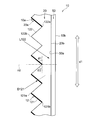
- the panel member according to the present invention includes a plurality of unit lenses arranged in at least one axial direction, A first optical functional surface located facing the plurality of unit lenses; A plurality of second optical functional surfaces arranged in the uniaxial direction and positioned between the plurality of unit lenses and the first optical functional surface, Each of the second optical functional surfaces is inclined with respect to the first optical functional surface,
- the unit lens guides light incident from a certain direction to the first optical functional surface, and guides light incident from another direction different from the certain direction to the second optical functional surface.
- Each of the second optical functional surfaces is disposed to face a unit lens corresponding to the second optical functional surface,
- Each of the second optical functional surfaces has an end located on one side in the uniaxial direction closer to the unit lens in the normal direction of the panel member than an end located on the other side in the uniaxial direction. Thus, it may be inclined with respect to the first optical function surface.
- a solar cell panel is provided facing the first optical function surface,
- the first optical functional surface may be a light incident surface of the solar cell panel.
- the second optical functional surface may be a display surface for performing display. Furthermore, a display target element may be provided to each of the second optical functional surfaces, and a display target may be formed by a combination of the display target elements.
- the panel member of the present invention it is possible to adjust the angular range in which the optical function from each optical function surface is continuously expressed with a high degree of freedom.
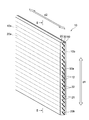
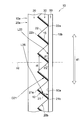
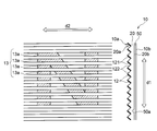
- FIG. 1 is a perspective view showing a solar cell composite display body, for explaining the first embodiment.
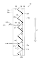
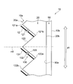
- FIG. 2 is a sectional view taken along line II-II in FIG.
- FIG. 3 is a diagram illustrating an example of a display target displayed on the solar cell composite display.
- FIG. 4 is a diagram for explaining the operation of the solar cell composite display body in the same cross section as FIG.
- FIG. 5 is a diagram for explaining the operation of the solar cell composite display body in the same cross section as FIG.
- FIG. 6 is a diagram for explaining a method for manufacturing a solar cell composite display.
- FIG. 7 is a diagram for explaining a method for manufacturing a solar cell composite display.
- FIG. 8 is a diagram for explaining a method of manufacturing a solar cell composite display.
- FIG. 1 is a perspective view showing a solar cell composite display body, for explaining the first embodiment.
- FIG. 2 is a sectional view taken along line II-II in FIG.
- FIG. 3 is a diagram illustrating an example
- FIG. 9 is a view corresponding to FIG. 2 and a cross-sectional view for explaining an optical path of light traveling toward the solar cell panel.
- FIG. 10 is a cross-sectional view showing a modification of the solar cell composite display shown in FIG.
- FIG. 11 is a cross-sectional view showing another modification of the solar cell composite display shown in FIG. 12 is a cross-sectional view showing still another modification of the solar cell composite display shown in FIG. 13 is a cross-sectional view showing still another modification of the solar cell composite display shown in FIG.
- FIG. 14 is a cross-sectional view showing still another modified example of the solar cell composite display shown in FIG.
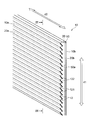
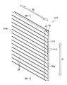
- FIG. 15 is a perspective view showing a solar cell composite display body for explaining the second embodiment.
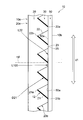
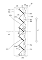
- FIG. 16 is a cross-sectional view taken along line XVI-XVI in FIG.
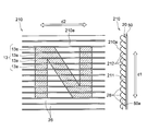
- FIG. 17 is a diagram illustrating an example of a display target displayed on the solar cell composite display.
- FIG. 18 is an enlarged view of the light transmission surface shown in FIG.
- FIG. 19 is a diagram for explaining the operation of the solar cell composite display body in the same cross section as FIG.
- FIG. 20 is a diagram for explaining the operation of the solar cell composite display body in the same cross section as FIG.
- FIG. 21 is a diagram corresponding to FIG. 18 and showing an example in which the display surface is provided movably with respect to the orientation adjustment surface.
- FIG. 22 is a view corresponding to FIG.
- FIG. 16 is a cross-sectional view showing an example in which a solar cell panel is joined to a main body through a reflection loss reducing layer.
- FIG. 23 is a perspective view illustrating a panel member for explaining the third embodiment. 24 is a cross-sectional view taken along line XXIV-XXIV in FIG.
- FIG. 25 is a diagram illustrating an example of a display target displayed on the panel member.
- FIG. 26 is a view for explaining the operation of the panel member in the same cross section as FIG.
- FIG. 27 is a view for explaining the operation of the panel member in the same cross section as FIG.
- FIG. 1 to 14 are diagrams for explaining a first embodiment of the present invention.
- 1 and 2 are perspective views or longitudinal sectional views showing the configuration of the solar cell composite display body 10, and FIGS. 3 to 5 and FIG. 9 illustrate the operation of the solar cell composite display body 10.
- FIG. FIG. 6 to FIG. 8 are diagrams for explaining an example of the method for manufacturing the solar cell composite display body 10.
- the solar cell composite display 10 described here exhibits both a predetermined display function and a power generation function using external light.
- the plurality of orientation adjustment surfaces 21 and the plurality of light transmission surfaces 22 alternately arranged in the first axis direction d ⁇ b> 1 are more incident than the solar cell panel 50.
- the display surface 12 disposed mainly on the orientation adjustment surface 21 is observed. Therefore, the display surface 12 exhibits a display function for an observer who observes the solar cell composite display body 10 from a certain angle range AR1.
- the solar cell panel 50 exhibits a power generation function with respect to light incident on the solar cell composite display body 10 from another certain angular range AR2.
- the solar cell panel 50 is used when the observer observes the display surface 12 by utilizing the difference between the observation direction from the observer and the incident direction of the external light. Visibility is suppressed and it is possible to achieve harmony with the surroundings.
- the solar cell composite display body 10 includes a sheet-like main body 20 and a solar cell panel 50 disposed on the back surface of the main body 20. .
- the main body 20 forms the front surface 10 a of the solar cell composite display body 10
- the solar cell panel 50 forms the back surface 10 b of the solar cell composite display body 10.
- the surface 10 a forms an incident surface for external light such as sunlight that enters the solar cell composite display body 10.
- the surface 10 a forms an emission surface from which light from the display surface 12 that visualizes the display object 13 (see FIG. 3) is emitted from the solar cell composite display body 10.
- the sheet-like main body 20 has a first surface 20a and a second surface 20b as a pair of main surfaces facing each other.
- the first surface 20 a forms the surface 10 a of the solar cell composite display body 10
- the second surface 20 b forms a surface facing the solar cell panel 50.
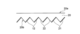
- the second surface 20b of the main body 20 includes a plurality of orientation adjustment surfaces 21 and a plurality of light transmission surfaces 22 that are alternately arranged in the first axial direction d1.
- a display surface 12 for displaying the display target 13 is disposed on the orientation adjustment surface 21.
- the orientation adjusting surface 21 is provided to support the display surface 12 and adjust the viewing angle at which the display surface 12 can be observed.
- the light transmission surface 22 is provided to transmit the light L22 incident on the solar cell composite display body 10 between the adjacent display surfaces 12 and guide the light L22 to the solar cell panel 50.
- the plurality of orientation adjustment surfaces 21 are configured identically, and the plurality of light transmission surfaces 22 are also configured identically.
- a “sheet” is a concept including a member that can also be called a film or a plate.
- the “sheet surface (film surface, plate surface, panel surface)” is the plane of the target sheet-like member when the target sheet-like member is viewed as a whole and globally. A surface that matches the direction.
- the sheet surface of the main body 20, the panel surface of the solar cell panel 50, and the light receiving surface 50 a of the solar cell panel 50 are parallel to each other.
- the “normal direction” used for a sheet-like (film-like, plate-like, panel-like) member refers to a normal direction to the sheet surface of the member.
- each orientation adjusting surface 21 and each light transmitting surface 22 extend linearly in a direction intersecting the first axial direction d1 that is the arrangement direction.
- each orientation adjustment surface 21 and each light transmission surface 22 extend linearly in a second axial direction d2 that is orthogonal to both the first axial direction d1 and the normal direction nd of the main body 20. ing.
- each orientation adjusting surface 21 and each light transmitting surface 22 are arranged so as to be shifted from each other when viewed from the normal direction nd.
- the first axial direction d1 and the second axial direction d2 are along the sheet surface of the main body 20 and are orthogonal to the normal direction nd of the main body 20.
- the solar cell composite display body 10 is arranged such that the first axial direction d1 is parallel to the vertical direction and the second axial direction d2 is parallel to the horizontal direction.
- Each orientation adjusting surface 21 is inclined with respect to the sheet surface of the main body 20, in other words, the panel surface of the solar cell panel 50, and is also inclined with respect to the normal direction nd of the main body 20. That is, each orientation adjustment surface 21 is not parallel to the seat surface of the main body 20 and the normal direction nd of the main body 20.
- the first angle range AR1 can be adjusted with a high degree of freedom.
- each orientation adjustment surface 21 has one end 21 a located on one side in the first axial direction d ⁇ b> 1 (in the illustrated example, the upper side in FIG. 2 and the upper side in the vertical direction)
- the solar cell panel in the normal direction nd of the main body 20 rather than the other end 21b located on the other side in the uniaxial direction d1 (in the example shown, the lower side in FIG. 2 and the lower side in the vertical direction).
- the main body 20 is inclined with respect to the seat surface so as to be separated from the main body 20. Therefore, the one end 21 a of the orientation adjusting surface 21 is farther from the solar cell panel 50 in the normal direction nd of the main body 20 than the other end 21 b of the orientation adjusting surface 21.
- such an orientation adjusting surface 21 makes it easier for light to be emitted toward an angle range inclined to the other side with respect to the normal direction nd. Therefore, the display function from the display surface 12 disposed on the orientation adjustment surface 21 is effectively exhibited when observed from the direction D21 inclined to the other side with respect to the normal direction nd.
- the orientation adjustment surface 21 is directed from one side (upper side) to the other side (lower side) in the first axial direction d1, It is preferable to approach the solar cell panel 50 in the normal direction nd of the main body 20 stepwise or continuously.
- the orientation adjustment surface 21 is formed as a flat surface.
- the orientation adjusting surface 21 is continuously at a constant inclination from one side to the other side in the first axial direction d1.
- the solar cell panel 50 is approached along the normal direction nd of the main body 20. According to such an orientation adjustment surface 21, when the display function from the display surface 12 arranged on the orientation adjustment surface 21 is observed from a direction D21 inclined to the other side with respect to the normal direction nd, an effect is obtained. Will come into play.
- the display surface 12 for displaying the display target 13 is arranged on the orientation adjustment surface 21.
- the display surface 12 is arranged along the orientation adjustment surface 21 so as to overlap the orientation adjustment surface 21. Therefore, the light emitted from the solar cell composite display 10 toward the first angle range AR1 from the display surface 12 visualizes the display target 13 applied to the display surface 12. That is, the display surface 12 is visually recognized from the first angle range AR1, and as a result, the display target 13 formed on the display surface 12 can be observed.
- FIG. 3 shows an example of the display object 13 formed on the display surface 12.
- a plurality of display surfaces 12 are arranged in the first axial direction d1, and each display surface 12 extends linearly in a second axial direction d2 orthogonal to the first axial direction d1. Therefore, the display surface 12 located at each position in the first axial direction d1 is provided with the display target element 13a corresponding to the position of the display surface 12 in the first axial direction d1, thereby causing the display surface 12 in the second axial direction d2.
- the two-dimensional display target 13 can be displayed as a combination of the display target elements 13a formed on the elongated display surfaces 12. In the example shown in FIG. 3, the capital letter “N” of the alphabet is displayed as the display target 13.
- each orientation adjustment surface 21 can be reduced by displaying the display target 13 as a combination of a plurality of display target elements 13a, the first angle range AR1 can be expanded or the solar cell composite display body 10 can be reduced. Even if the size is increased, a better display object 13 can be observed.
- the solar cell composite display body 10 of the present embodiment can adjust the angular range in which the display target 13 is continuously displayed with a high degree of freedom. Therefore, the solar cell composite display body 10 of the present embodiment can be used for various purposes.
- the solar cell composite display body 10 has a size of several meters to several tens of meters used for outdoor signboards, road information bulletin boards, outer wall surfaces of buildings, and the like. Large panel use, medium size panel use of several tens of centimeters to several meters used for posters, signs, inner walls of buildings, etc., and small panel of several centimeters to several tens of centimeters used for table lamps, portable terminals, etc. Applications can be exemplified.
- each light transmission surface 22 located between the adjacent orientation adjustment surfaces 21 is inclined with respect to the sheet surface of the main body 20, in other words, the panel surface of the solar cell panel 50, and the normal direction of the main body 20. It is also inclined with respect to nd. That is, each orientation adjustment surface 21 is not parallel to the seat surface of the main body 20 and the normal direction nd of the main body 20.
- the second angle range AR2 that is an angle range in which power generation by the solar cell panel 50 is continuously performed stably is increased. It is possible to adjust with a degree of freedom.
- the angle at which the light transmission surface 22 is inclined with respect to the sheet surface of the main body 20 is different from the angle at which the direction adjustment surface 21 is inclined with respect to the sheet surface of the light control sheet 20.
- the light transmission surface 22 is inclined to the opposite side of the orientation adjustment surface 21 with respect to the normal direction nd of the main body 20.
- each orientation adjustment surface 21 is positioned with respect to the sheet surface of the main body 20 so that the one end 21a is separated from the solar cell panel 50 in the normal direction nd of the main body 20 than the other end 21b. It is inclined.
- each light transmission surface 22 has a second end portion 22b positioned on the other side in the first axial direction d1 and a normal direction of the main body portion 20 relative to the first end portion 22a positioned on one side in the first axial direction d1. It inclines with respect to the sheet surface of the main-body part 20 so that it may space apart from the solar cell panel 50 in nd. As can be understood from FIG. 2, light from an angle range inclined to one side with respect to the normal direction nd is easily incident on such a light transmission surface 22. Therefore, the light L22 incident on the solar cell composite display 10 from a direction inclined to one side with respect to the normal direction nd can be easily guided by the solar cell panel 50.
- the light transmission surface 22 is stepwise or continuously from the other side to the one side in the first axial direction d1
- the light transmission surface 22 is formed as a flat surface.
- the light transmission surface 22 is continuously inclined at a certain degree from the other side to the one side in the first axial direction d1.
- the solar cell panel 50 is approached along the normal direction nd of the main body 20. According to such a light transmission surface 22, the light L ⁇ b> 22 incident on the solar cell composite display body 10 from a direction inclined to one side with respect to the normal direction nd can be easily guided by the solar cell panel 50.
- the orientation adjustment surface 21 and the light transmission surface 22 will be described.
- the distance dt along the line becomes narrower stepwise or continuously as it approaches the solar cell panel 50 in the normal direction nd of the main body 20.
- the distance dt along the first axial direction d1 between each position on the orientation adjusting surface 21 and the light transmitting surface 22 adjacent to the orientation adjusting surface 21 on the other side in the first axial direction d1 is As the position on the orientation adjustment surface 21 approaches the solar cell panel 50 along the normal direction nd of the main body 20, it becomes narrower stepwise or continuously. Therefore, the other end 21b of the orientation adjusting surface 21 is closest to the one end 22a of the light transmitting surface 22 located on the other side. In the illustrated embodiment, the other end 21b of the orientation adjusting surface 21 is connected to one end 22a of the light transmitting surface 22 located on the other side. But the other end part 21b of the direction adjustment surface 21 may be spaced apart from the one end part 22a of the light transmission surface 22 located in the other side.
- one end 21a of the orientation adjustment surface 21 is connected to the other end 22b of the light transmission surface 22 adjacent to the orientation adjustment surface 21 on one side in the first axial direction d1.
- the one end portion 21a of the orientation adjustment surface 21 may be separated from the other end portion 22b of the light transmission surface 22 adjacent to the orientation adjustment surface 21 on one side in the first axial direction d1.
- the orientation adjustment surface 21 is equal to the length of the light transmission surface 22 adjacent to the orientation adjustment surface 21. Therefore, the ratio of the orientation adjustment surface 21 occupying the second surface 20 b of the main body 20 is equal to the ratio of the light transmission surface 22 occupying the second surface 20 b of the main body 20.
- the orientation adjustment surface 21 may be different from the length of the light transmission surface 22 adjacent to the orientation adjustment surface 21.
- the ratio of the orientation adjustment surface 21 to the second surface 20 b of the body portion 20 is set to the It can be made smaller than the ratio of the light transmission surface 22 to the two surfaces 20b. In this case, a relatively large amount of light tends to be easily guided to the light transmission surface 22, and as a result, more light can be contributed to the solar cell panel 50.
- the angle ⁇ ⁇ b> 1 formed by the orientation adjustment surface 21 with respect to the sheet surface of the main body 20 is equal to the angle ⁇ ⁇ b> 2 formed by the light transmission surface 22 with respect to the sheet surface of the main body 20.
- the angle ⁇ 1 formed by the orientation adjustment surface 21 with respect to the sheet surface of the main body 20 is determined according to the observation direction of the observer intended to be observed, and the light transmission surface 22 is the sheet of the main body 20.
- the angle ⁇ 2 formed with respect to the surface is determined in accordance with the incident direction of external light that is intended to be captured. Therefore, the angle ⁇ 1 formed by the orientation adjustment surface 21 with respect to the sheet surface of the main body 20 may be different from the angle ⁇ 2 formed by the light transmission surface 22 with respect to the sheet surface of the main body 20.
- each orientation adjusting surface 21 and each light transmitting surface 22 are flat surfaces. However, it is not limited to such an example, and each direction adjustment surface 21 and each light transmission surface 22 may consist of curved surfaces. As an example, each orientation adjustment surface 21 and each light transmission surface 22 may form a part of a spherical surface or a curved surface such as a lens surface. More specifically, each orientation adjusting surface 21 and each light transmitting surface 22 may be lens surfaces curved so as to be convex toward the outer side, or concave toward the inner side. A curved lens surface may be used.
- the orientation adjustment surface 21 is a curved surface
- “the orientation adjustment surface 21 is inclined with respect to the plane” means that the straight line connecting both end portions 21a and 21b of the orientation adjustment surface 21 is flat in the main cut surface shown in FIG. It means to be inclined with respect to.
- the angle ⁇ 1 formed by the orientation adjusting surface 21 with respect to the sheet surface of the main body portion 20 is such that a straight line connecting both end portions 21a and 21b of the orientation adjusting surface 21 in the main cut surface shown in FIG. This is the angle made with respect to.
- the light transmission surface 22 is a curved surface
- “the light transmission surface 22 is inclined with respect to the plane” means that both end portions 22a and 22b of the light transmission surface 22 are connected in the main cut surface shown in FIG.
- the straight line is inclined with respect to the plane.
- the angle ⁇ 2 formed by the light transmission surface 22 with respect to the sheet surface of the main body portion 20 is such that a straight line connecting both end portions 22a and 22b of the light transmission surface 22 is the sheet surface of the main body portion 20 in the main cut surface shown in FIG. This is the angle made with respect to.
- a point protruding from the second surface 20 b of the main body 20 so as to approach the solar cell panel 50 along the normal direction nd of the main body 20 is defined as the top 23.
- the top 23 is defined as a connection position between one end 22 a of one light transmission surface 22 and the other end 21 b of one orientation adjustment surface 21.
- the solar cell panel 50 is disposed so as to be in contact with the top 23 of the main body 20, and the air layer 30 is formed between the second surface 20 b of the main body 20 and the solar cell panel 50. .
- the air layer 30 is formed in a space surrounded by the orientation adjustment surface 21 of the main body 20, the light transmission surface 22 of the main body 20, and the light receiving surface 50 a of the solar cell panel 50.
- the solar cell panel 50 is not limited to the example arrange
- the main-body part 20 is not limited to the example arrange
- the solar cell panel 50 is a power generator that converts light received by the light receiving surface 50a into electric energy.
- Light L22 taken into the light transmission surface 22 from the second angle range AR2 is guided to the light receiving surface 50a of the solar cell panel 50, and this light L22 is used for power generation.
- the solar cell panel 50 extends in a planar shape so as to face each of the plurality of orientation adjustment surfaces 21 and the plurality of light transmission surfaces 22 arranged in the first axial direction d1.
- the solar cell panel 50 extends in parallel with the sheet surface of the main body 20. Therefore, in the illustrated example, the first optical functional surface 211 extends in parallel with the first axial direction d1 that is the direction in which the orientation adjusting surface 21 and the light transmitting surface 22 are arranged, and the orientation adjusting surface 21 and the light transmitting surface.
- the second axial direction d2 which is the longitudinal direction of 22 extends in parallel and spreads.
- a solar cell panel 50 various forms can be used.
- a silicon-based solar cell panel, a thin-film solar cell panel, a chalcopyrite solar cell, or the like including a flat silicon substrate made of single crystal silicon or polycrystalline silicon can be used as the solar cell panel 50.
- the main body 20 is produced by molding a transparent resin.
- hot-melt extrusion processing, injection molding, or the like can be employed.
- a plurality of orientation adjustment surfaces 21 and a plurality of light transmission surfaces 22 are alternately formed on the second surface 20 b of the main body 20 obtained.
- the display surface 12 is formed on the orientation adjustment surface 21 of the main body 20.
- the display surface 12 is formed on the orientation adjustment surface 21 of the main body 20 by inkjet printing.
- the solar cell panel 50 is disposed to face the second surface 20 b of the main body 20. Thereby, the solar cell composite display 10 is obtained.
- the solar cell composite display 10 is arranged such that the first axial direction d1 that is the arrangement direction of the orientation adjustment surface 21 and the light transmission surface 22 is along the vertical direction.
- the solar cell composite display 10 is arranged such that one side in the first axial direction d1 is along the upper side in the vertical direction and the other side in the first axial direction d1 is along the lower side in the vertical direction.
- the display surface 12 arranged on the inclined orientation adjustment surface 21 is easily visible from the front direction of the display surface 12.
- the display surface 12 is inclined to one side in the first axial direction d1 with respect to the normal direction nd of the main body portion 20, and therefore the first axial direction d1 with respect to the normal direction nd.
- the solar cell composite display 10 is observed from the directions D41, D42, and D43 inclined to the other side, the display surface 12 is easily visually recognized.
- the first angle range AR1 serving as a viewing angle at which the display surface 12 located on the orientation adjustment surface 21 is observed is It can be adjusted with a high degree of freedom. Therefore, the observer can observe the display target 13 with excellent visibility and can display the display target 13 with excellent design.
- the light transmission surface 22 inclined at a different angle from the direction adjustment surface 21 efficiently transmits the light L51, L52, and L53 incident from a direction different from the directions D41, D42, and D43 in which the direction adjustment surface 21 is easily visible. It is possible to capture.
- the light transmission surface 22 is inclined to the other side in the first axial direction d1 with respect to the normal direction nd of the main body 20, and thus the first axial direction with respect to the normal direction nd.
- Light L51, L52, and L53 incident on the solar cell composite display body 10 from a direction inclined to one side in d1 can be efficiently taken.
- the lights L51, L52, and L53 taken into the light transmission surface 22 travel through the air layer 30 and are guided to the solar cell panel 50.
- the solar cell composite display body that is guided to the solar cell panel 50 by inclining the light transmission surface 22 with respect to the normal direction nd of the main body portion 20 at an angle different from that of the orientation adjustment surface 21. 10 can be adjusted with a high degree of freedom. Therefore, in the solar cell composite-type display body 10 according to the present embodiment, sunlight that changes the incident direction according to the time zone and season is efficiently received and used for power generation in the solar cell panel 50. Is possible.
- the sheet-like main body 20 having the first surface 20a and the second surface 20b facing the first surface 20a, and the second surface 20b of the main body 20 are opposed to each other.
- the second surface 20b of the main body 20 includes a plurality of orientation adjustment surfaces 21 and a plurality of light transmission surfaces 22 arranged alternately in the first axial direction d1.
- the orientation adjusting surface 21 is inclined with respect to the panel surface of the solar cell panel 50, and the light transmitting surface 22 is inclined with respect to the panel surface of the solar cell panel 50 at an angle different from that of the orientation adjusting surface 21.
- a display surface 12 for performing display is disposed on the adjustment surface 21.
- the inclined direction adjustment surface 21 and the light transmission surface 22 are inclined with respect to the panel surface of the solar cell panel 50, the inclined direction adjustment surface 21 and the light transmission surface are inclined. 22 makes it easy to effectively use light incident from the front direction.
- the light transmission surface 22 is inclined with respect to the panel surface of the solar cell panel 50 at an angle different from that of the orientation adjustment surface 21.
- the display surface 12 arranged on the orientation adjusting surface 21 has a solar cell composite display body from directions D21 and D41 to D43 that are different from the directions in which the light L22 and L51 to L53 that are easily taken into the light transmitting surface 22 are inclined.
- the light transmitting surface 22 is incident on the solar cell composite display body 10 from a direction different from the directions D21 and D41 to D43 in which the orientation adjusting surface 21 is easily visible. Takes in L53 effectively.
- the first angle range AR1 and the second angle range AR2 that is an angle range in which power generation is continuously performed stably in the solar cell panel 50 can be adjusted with a high degree of freedom.
- the solar cell panel 50 is disposed to face the second surface 20b of the main body 20, the light receiving surface 50a of the solar cell panel 50 is not exposed to the outside. For this reason, the solar cell panel 50 can be made inconspicuous. For these reasons, according to the present embodiment, it is possible to achieve harmony with the surrounding environment and effectively achieve both the display on the display surface 12 and the power generation by the solar cell panel 50.
- the first angle range AR1 in which the display surface 12 can be observed is separated from the second angle range AR2 in which the solar cell panel 50 can be observed, that is, does not overlap.
- the orientation adjustment surface 21 is opposite to the light transmission surface 22 with respect to the normal direction nd of the main body 20 in the main cut surface shown in FIG. It is inclined to.
- the display surface 12 arranged on the orientation adjustment surface 21 is from directions D21 and D41 to D43 that are opposite to the directions in which the light L22 and L51 to L53 that are easily taken into the light transmission surface 22 are inclined.
- the orientation adjustment surface 21 is inclined with respect to the seat surface of the main body 20 so that the one end 21a is farther from the solar cell panel 50 in the normal direction nd of the main body 20 than the other end 21b.
- the light transmission surface 22 is inclined with respect to the sheet surface of the main body 20 so that the other end 22b is separated from the solar cell panel 50 in the normal direction nd of the main body 20 than the one end 22a.
- the solar cell composite display 10 is observed from the directions D21 and D41 to D43 inclined to the other side in the first axial direction d1 with respect to the normal direction nd of the main body 20, the light transmitting surface 22 is used.
- the display surface 12 arranged on the orientation adjusting surface 21 can be easily selectively observed.
- the light L22 and L51 to L53 incident on the solar cell composite display body 10 from the direction inclined to one side in the first axial direction d1 with respect to the normal direction nd of the main body 20 is more than the direction adjustment surface 21.
- the light transmission surface 22 can be guided to selection.
- the first angle range AR1 that is a viewing angle at which the display surface 12 arranged on the orientation adjustment surface 21 can be observed is the first axis with respect to the normal direction nd of the main body 20.
- the second angle range that corresponds to the direction inclined to the other side in the direction d1 and is the angle range in the incident direction to the solar cell composite display 10 that is guided to the solar cell panel 50 through the light transmission surface 22.
- AR2 corresponds to a direction inclined to one side in the first axial direction d1 with respect to the normal direction nd of the main body 20. For this reason, the first angle range AR1 and the second angle range AR2 are easily divided. In other words, the first angle range AR1 and the second angle range AR2 are difficult to overlap.
- the display function by the display surface 12 and the power generation function by the solar battery panel 50 are more effectively performed without adversely affecting each other. Will come to be.
- the first angle range AR1 serving as a viewing angle at which the display surface 12 can be observed is set in a direction inclined downward in the vertical direction, and the solar cell panel 50
- the second angle range AR2 that is the angle range in the incident direction to the solar cell composite display body 10 that is guided to is set in a direction inclined upward in the vertical direction.
- the observer can observe the display object 13 given to the display surface 12 from the first angle range AR1 in order to observe the solar cell composite display 10 while looking up upward in the vertical direction.
- the interval dt along the first axial direction d1 becomes narrower as the solar cell panel 50 is approached in the normal direction nd of the main body 20.
- the display surface 12 disposed on the orientation adjustment surface 21 blocks light that should be incident on the light transmission surface 22, or the light transmission surface 22 is disposed on the orientation adjustment surface 21. It is possible to effectively suppress the observation of the displayed display surface 12 from being interrupted.
- the display surface 12 observes the solar cell composite display body 10 from the direction within the first angle range AR1, the display function can be more reliably exhibited. Further, the light transmission surface 22 can more reliably guide the light incident on the solar cell composite display body 10 from the second angle range AR2 to the solar cell panel 50.
- the large-sized solar cell panel 50 is disposed so as to face the second surface 20 b of the main body 20.
- a small solar cell panel 50 on each light transmission surface 22 and use a large number of solar cell panels 50 as a whole.
- the large-sized solar cell panel 50 is arranged to face each light transmission surface 22. In this case, since the solar cell panel 50 can be arrange
- the sheet-like main body portion 20 having the first surface 20a and the second surface 20b facing the first surface 20a and the second surface 20b of the main body portion 20 are disposed to face each other.
- a plurality of display surfaces 12 each inclined with respect to the panel surface of the solar cell panel 50 are arranged along the uniaxial direction d1.
- a mold display 10 is provided.
- Table 1 below shows the south-high altitude (°) for each season in major cities in some countries of the world. It is preferable that the south and middle altitudes of the equinox in the major cities of the country where the use is assumed be included in the second angle range AR2. This is because there is a high possibility that it can be used effectively in that country. For example, when the country assumed to be used is Japan, the altitude from 54 ° to 56 ° may be included in the second angle range AR2. Furthermore, it is preferable that an altitude from 49 ° to 61 ° is included in the second angle range AR2, since there is a high possibility that it can be used effectively in many countries in the world.
- the second angle range AR2 includes a range from the southern middle altitude of the summer solstice to the southern middle altitude of the winter solstice in the main cities of the country assumed to be used. This is because there is a high possibility that it can be used effectively throughout the year in that country. For example, when the country assumed to be used is Japan, the altitude from 31 ° to 79 ° may be included in the second angle range AR2. Furthermore, it is preferable that an altitude of 25 ° to 84 ° is included in the second angle range AR2, since there is a high possibility that it can be used effectively in many countries in the world.
- the angle range of the second angle range AR2 is continuous by about 45 ° or more.
- the upper limit of the angle range of the second angle range AR2 may be appropriately set in balance with the first angle range AR1, but by setting it to less than about 135 °, the solar cell composite display according to the present embodiment. The features of the body 10 can be exhibited more.
- FIG. 9 an example of the optical path of the sunlight which goes to the solar cell panel 50 is shown.
- the incident angle when the light L23 intended to be incident on the light transmission surface 22 is incident on the first surface 20a of the main body 20 is ⁇ 0 (0 ° ⁇ ⁇ 0 ⁇ 90 °).
- the refraction angle at which the light L23 is refracted by the first surface 20a of the main body 20 is ⁇ 1.
- the incident angle ⁇ 0 is an angle formed by the light L23 incident on the first surface 20a with respect to the normal direction of the first surface 20a
- the refraction angle ⁇ 1 is the light L23 refracted by the first surface 20a. This is an angle formed with respect to the normal direction of the first surface 20a.
- the normal direction of the first surface 20 a coincides with the normal direction nd of the main body 20.
- the refractive index of the air layer is n0
- an incident angle when the light L23 transmitted through the first surface 20a of the main body 20 enters the light transmission surface 22 is ⁇ 2. That is, the incident angle ⁇ 2 is an angle formed by the light L23 incident on the light transmission surface 22 with respect to the normal direction nd1 of the light transmission surface 22.
- the incident angle ⁇ 2 at that time should be smaller than the total reflection critical angle at the light transmitting surface 22, n1 ⁇ SIn ⁇ 2 ⁇ n0 ⁇ 1 (2) It becomes.
- Equation (5) indicates that the incident angle ⁇ 2 when the light L24 incident on the first surface 20a of the main body 20 along the normal direction nd of the main body 20 is incident on the light transmission surface 22 is the light transmission
- the conditions when the total reflection critical angle at the surface 22 is smaller than the above are shown. Therefore, by determining the refractive index n1 of the main body 20 and the angle ⁇ 2 of the light transmission surface 22 so as to satisfy this formula (5), the first main body 20 is aligned along the normal direction nd of the main body 20.
- the light L24 incident on the surface 20a can go to the solar cell panel 50 without being totally reflected by the light transmission surface 22.
- any light incident on the first surface 20a from a direction inclined to one side in the first axial direction d1 with respect to the normal direction nd of the main body portion 20 is mainly light.
- the light transmission surface 22 can be transmitted without being totally reflected by the transmission surface 22.
- the solar cell composite display 10 is installed so that one side in the first axial direction d1 corresponds to the upper side in the vertical direction and the normal direction nd of the main body 20 corresponds to the horizontal direction. . Therefore, when Expression (5) is satisfied, it is possible to guide sunlight incident on the first surface 20a from the direction inclined upward in the vertical direction to the solar cell panel 50 without being totally reflected mainly by the light transmission surface 22. It becomes.
- FIG. 10 shows another form of the shape of the top portion 23.
- the top portion 23 is configured as a flat surface 25 along the first surface 20a, and is a position farthest from the first surface 20a along the normal direction nd of the second surface 20b. Is arranged.
- Each flat surface 25 includes the other end portion (end portion located on the solar cell panel 50 side) 21b of the orientation adjustment surface 21, and one end portion (end portion located on the solar cell panel 50 side) 21a of the light transmission surface 22. , Between these ends are connected to each other.
- the flat surface 25 is disposed along the first surface 20a of the main body 20, the light L100 incident on the first surface 20a of the main body 20 from the direction along the normal direction nd according to the flat surface 25. Can be guided to the solar cell panel 50 with high transmittance. Further, vibration or impact is transmitted to the solar cell composite display 10 during transportation or transportation, and the top 23 of the main body 20 may come into contact with the solar cell panel 50 and be damaged, but the example shown in FIG. According to this, the flat surface 25 can be in contact with the solar cell panel 50 and stably supported, thereby reducing the possibility that the top 23 is damaged.
- the reflective surface 15 may be further disposed so as to overlap the display surface 12.
- FIG. 11 shows an example in which the reflective surface 15 is placed on the display surface 12.
- the display surface 12 faces the first surface 20a, and the reflecting surface 15 faces the second surface 20b. That is, each reflecting surface 15 is disposed so as to be back-to-back with the corresponding display surface 12.
- Such a reflective surface 15 is formed by a thin film made of a material having a high reflectance as an example.
- the reflection surface 15 the light incident on the light transmission surface 22 of the main body 20 from a direction that is extremely inclined to one side (upper side in FIG. 11) in the first axial direction d 1 with respect to the normal direction nd of the main body 20. Even when the light L25 is refracted by the light transmitting surface 22 and approaches the display surface 12 from the back surface side (second surface 20b side), the light L25 is reflected by the reflecting surface 15 and directed to the solar cell panel 50. You can make it. Therefore, by providing the reflecting surface 15, the second angle range AR2 corresponding to the incident angle range of the light guided to the solar cell panel 50 can be further widened. Thereby, the sunlight which changes an incident direction according to a time zone and a season can be efficiently utilized for power generation by the solar cell panel 50.
- the diffusing element 35 may be further provided in the optical path of the light transmitted through the light transmission surface 22 toward the solar cell panel 50.
- FIG. 12 shows an example in which a diffusion layer 35 is further provided. As shown in FIG. 12, the diffusing element 35 is disposed in a region including a region between the light transmission surface 22 and the solar cell panel 50. In particular, in the example shown in FIG. 12, the diffusing element 35 forms a diffusing layer laminated on the entire light receiving surface 50 a of the solar cell panel 50.
- the diffusing element 35 includes a main portion 35a and a diffusion component 35b that scatters light dispersed in the main portion 35a.
- the diffusion component 35b here is a component that can act on the light traveling in the diffusion element 35 by changing the path direction of the light by reflection or refraction.
- a light scattering function of the diffusing component 35b can be achieved by, for example, forming the diffusing component 35b from a material having a refractive index different from that of the material forming the main portion 35a of the diffusing element 35, or Can be applied by constructing the diffusing component 35b from a material that can have a reflective effect on.
- Examples of the diffusion component 35b having a refractive index different from that of the material forming the main portion 35a include a metal compound, a porous substance containing gas, and simple bubbles.
- the light L 26 that is transmitted through the light transmitting surface 22 toward the solar cell panel 50 is diffused by the diffusing element 35.
- the light L26 diffused by the diffusing element 35 reaches a wide area of the solar cell panel 50. For this reason, the part which the solar cell panel 50 is not irradiated can be reduced, and it can suppress that the output of the solar cell panel 50 is reduced.
- FIG. 13 the other form of the solar cell composite display 10 is shown.
- the solar cell composite display body 10 is located in the valley region V between the two adjacent top portions 23 forming the second surface 20 b of the main body 20, and the valley region V It further has a low refractive index layer 38 that fills at least a portion.
- the low refractive index layer 38 covers the second surface 20b of the main body 20 and the light receiving surface 50a of the solar cell panel 50 without any gap.
- the refractive index of the low refractive index layer 38 is different from the refractive index of the main body 20. For this reason, a refractive index difference is generated at the interface between the low refractive index layer 38 and the main body 20.
- the refractive index of the low refractive index layer 38 of the present embodiment is lower than the refractive index of the main body portion 20.
- the low-refractive index layer 38 by filling at least a part of the valley region V between the two adjacent top portions 23, it is possible to increase the resistance against pressing of the main body portion 20 against the second surface 20b. .
- a plurality of unit lenses 28 may be arranged on the first surface 20a of the main body 20.
- FIG. 14 shows an example in which a plurality of unit lenses 28 are further provided. As shown in FIG. 14, the plurality of unit lenses 28 are arranged such that their optical axes od are parallel to each other. In particular, in the illustrated example, the unit lens 28 is arranged so that its optical axis od is parallel to the normal direction nd of the main body 20. Further, in the example shown in FIG. 14, one orientation adjusting surface 21 and a light transmitting surface 22 are arranged to face one unit lens 28.
- the unit lens 28 constitutes a so-called lenticular lens or cylindrical lens. That is, each unit lens 28 extends linearly in a direction intersecting the first axis direction d1 that is the arrangement direction thereof. In particular, in the illustrated example, the unit lens 28 extends linearly in a second direction d2 orthogonal to both the first axial direction d1 and the normal direction nd. Further, the plurality of unit lenses 28 are configured identically to each other.
- the unit lens 28 has a convex lens-like lens surface 28a.
- the lens surface 28 a forms the surface 10 a of the solar cell composite display body 10.
- the lens surface 28a is symmetric about the optical axis od.
- Each unit lens 28 collects a parallel light beam incident on its lens surface 28a on the focal point fp.
- the focal point fp shown in FIG. 14 is a focal point for the parallel light L27 incident along the optical axis od of the unit lens 28, and is therefore located on the optical axis od of the unit lens 28.
- Second Embodiment a second embodiment will be described with reference to FIGS.
- the second embodiment described with reference to FIGS. 15 to 22 is different in that the orientation adjustment surface 121 and the light transmission surface 122 are included in the first surface 20a of the main body 20, but the other configurations are as follows. It can be configured in the same manner as the first embodiment and its modifications.
- the first embodiment described above and the parts thereof that can be configured in the same manner as in the first embodiment described above and the modifications thereof are described.
- the same reference numerals as those used for the corresponding parts in the modification are used, and redundant description is omitted.
- FIG. 16 and FIG. 18 are perspective views or longitudinal sectional views showing the configuration of the solar cell composite display body 10 in the second embodiment, and FIG. 17, FIG. 19 and FIG. It is a figure for demonstrating the effect
- the solar cell composite display 10 includes a sheet-like main body 20 and a solar cell panel 50 bonded to the second surface 20 b of the main body 20. Have.
- the first surface 20a of the main body 20 includes a plurality of orientation adjustment surfaces 121 and a plurality of light transmission surfaces 122 arranged alternately in the first axial direction d1.
- a display surface 12 for displaying the display target 13 is arranged on the orientation adjustment surface 121.
- each orientation adjusting surface 121 and each light transmitting surface 122 intersect with the first axis direction d1 that is the arrangement direction, more specifically, the first axis direction d1 and the normal line. It extends linearly in a second axial direction d2 perpendicular to both directions nd.
- each orientation adjustment surface 121 and each light transmission surface 122 are arranged so as to be shifted from each other when viewed from the normal direction nd.
- Each orientation adjusting surface 121 is inclined with respect to the sheet surface of the main body 20, in other words, the panel surface of the solar cell panel 50, and is also inclined with respect to the normal direction nd of the main body 20.
- the first angle range AR1 can be adjusted with a high degree of freedom.
- each orientation adjusting surface 121 has one end 121a located on one side in the first axial direction d1 (in the example shown, the upper side in FIG. 16 and the upper side in the vertical direction).
- the solar cell panel in the normal direction nd of the main body 20 rather than the other end 121b located on the other side in the uniaxial direction d1 (in the example shown, the lower side in FIG. 16 and the lower side in the vertical direction).
- the main body 20 is inclined with respect to the seat surface so as to be separated from the main body 20. Therefore, one end 121 a of the orientation adjustment surface 121 is farther from the solar cell panel 50 in the normal direction nd of the main body 20 than the other end 121 b of the orientation adjustment surface 121.
- such an orientation adjustment surface 121 makes it easier for light to be emitted toward an angle range inclined to the other side with respect to the normal direction nd. Therefore, the display function from the display surface 12 arranged on the orientation adjustment surface 121 is effectively exhibited when observed from the direction D21 inclined to the other side with respect to the normal direction nd.
- the orientation adjustment surface 121 is directed from one side (upper side) to the other side (lower side) in the first axial direction d1, It is preferable to approach the solar cell panel 50 in the normal direction nd of the main body 20 stepwise or continuously.
- the orientation adjustment surface 121 is formed as a flat surface.
- the orientation adjusting surface 121 is continuously inclined at a certain inclination from one side to the other side in the first axial direction d1.
- the solar cell panel 50 is approached along the normal direction nd of the main body 20. According to such an orientation adjustment surface 121, when the display function from the display surface 12 arranged on the orientation adjustment surface 121 is observed from a direction D21 inclined to the other side with respect to the normal direction nd, an effect is obtained. Will come into play.
- the display surface 12 for displaying the display target 13 is arranged on the orientation adjustment surface 121.
- the display surface 12 is arranged along the orientation adjustment surface 121 so as to overlap the orientation adjustment surface 121. Therefore, the light emitted from the solar cell composite display 10 toward the first angle range AR1 from the display surface 12 visualizes the display target 13 applied to the display surface 12.
- FIG. 17 shows an example of the display target 13 formed on the display surface 12.
- a plurality of display surfaces 12 are arranged in the first axial direction d1, and each display surface 12 extends linearly in a second axial direction d2 orthogonal to the first axial direction d1. Therefore, the display surface 12 located at each position in the first axial direction d1 is provided with the display target element 13a corresponding to the position of the display surface 12 in the first axial direction d1, thereby causing the display surface 12 in the second axial direction d2.
- the two-dimensional display target 13 can be displayed as a combination of the display target elements 13 a formed on the first optical function surfaces 211 that are elongated.
- each light transmission surface 122 positioned between the adjacent orientation adjustment surfaces 121 is inclined with respect to the sheet surface of the main body 20, in other words, the panel surface of the solar cell panel 50, and the normal direction of the main body 20. It is also inclined with respect to nd.
- the second angle range AR2 that is an angle range in which power generation by the solar cell panel 50 is continuously performed stably is increased. It is possible to adjust with a degree of freedom.
- the angle at which the light transmitting surface 122 is inclined with respect to the sheet surface of the main body 20 is different from the angle at which the orientation adjusting surface 121 is inclined with respect to the sheet surface of the light control sheet 20.
- the light transmission surface 122 is inclined to the opposite side of the orientation adjustment surface 121 with respect to the normal direction nd of the main body 20.
- each orientation adjustment surface 121 is positioned with respect to the sheet surface of the main body 20 so that the one end 121a is separated from the solar cell panel 50 in the normal direction nd of the main body 20 relative to the other end 121b. Inclined.
- each light transmission surface 122 has a normal direction of the main body portion 20 at the other end portion 122b located on the other side in the first axial direction d1 rather than the one end portion 122a located on one side in the first axial direction d1. It inclines with respect to the sheet surface of the main-body part 20 so that it may space apart from the solar cell panel 50 in nd. As can be understood from FIG. 16, light from an angle range inclined to one side with respect to the normal direction nd is easily incident on such a light transmission surface 122. Therefore, the solar cell panel 50 can easily guide the light L122 incident on the solar cell composite display body 10 from the direction inclined to one side with respect to the normal direction nd.
- the light transmission surface 122 is gradually or continuously from the other side to the one side in the first axial direction d1
- the light transmission surface 122 is formed as a flat surface.
- the light transmission surface 122 is continuously at a constant inclination from the other side to the one side in the first axial direction d1.
- the solar cell panel 50 is approached along the normal direction nd of the main body 20. According to such a light transmission surface 122, the solar cell panel 50 can easily guide the light L122 incident on the solar cell composite display 10 from a direction inclined to one side with respect to the normal direction nd.
- the light transmission surface 122 captures light incident from a wide angle range in order to guide more light to the solar cell panel 50. For this reason, depending on the incident angle of the light incident on the light transmission surface 122, the reflection loss of light increases. Therefore, in the solar cell composite display 10 according to the present embodiment, a contrivance is made to reduce the reflection loss of light on the light transmission surface 122.
- FIG. 18 shows the light transmission surface 122 in an enlarged manner.
- an antireflection layer 115 is laminated on the light transmission surface 122.
- the antireflection layer 115 includes a plurality of layers 116 to 118 stacked in order from the light transmission surface 122 side, and each of the layers 116 to 118 is another layer positioned closer to the light transmission surface 122 than the layers 116 to 118.
- the refractive index is lower than 116 and 117.
- the antireflection layer 115 includes a first layer 116, a second layer 117, and a third layer 118 that are sequentially stacked from the light transmission surface 122 side.
- the third layer 118 has a lower refractive index than the first layer 116 and the second layer 117, and the second layer 117 has a lower refractive index than the first layer 116.
- the refractive index increases as the layers 116 to 118 positioned closer to the light transmission surface 122 and the refractive index difference can be gradually changed. The reflection loss of light can be effectively reduced.
- the first layer 116 positioned close to the light transmission surface 122 is formed of a resin layer, and the second layer 117 superimposed on the first layer 116 has a refractive index higher than that of the resin forming the first layer 116.
- the third resin layer 118 may be formed of a low resin layer, and the third layer 118 overlaid on the second layer 117 may be formed of a vapor deposition layer containing an inorganic substance having a low refractive index as a main component.
- the aspect of reducing the reflection loss of light on the light transmission surface 122 is not limited to such an example.
- the antireflection layer may be a layer having a moth-eye structure including a large number of minute protrusions.
- a number of texture structures may be provided on the light transmission surface 122 to reduce light reflection loss.
- the orientation adjustment surface 121 In the main cross section of the solar cell composite display shown in FIG. 16, the first axial direction d1 of the orientation adjusting surface 121 and the light transmitting surface 122 adjacent to the orientation adjusting surface 121 on the other side in the first axial direction d1.
- the distance along the line becomes narrower stepwise or continuously as it approaches the solar cell panel 50 in the normal direction nd of the main body 20. Therefore, the other end 121b of the orientation adjustment surface 121 is closest to the one end 122a of the light transmission surface 122 located on the other side.
- the other end 121b of the orientation adjustment surface 121 is connected to one end 122a of the light transmission surface 122 located on the other side. But the other end part 121b of the direction adjustment surface 121 may be spaced apart from the one end part 122a of the light transmission surface 122 located in the other side.
- one end 121a of the orientation adjustment surface 121 is connected to the other end 122b of the light transmission surface 122 adjacent to the orientation adjustment surface 121 on one side in the first axial direction d1.
- the one end 121a of the orientation adjustment surface 121 may be separated from the other end 122b of the light transmission surface 122 adjacent to the orientation adjustment surface 121 on one side in the first axial direction d1.
- the orientation adjustment surface 121 is equal to the length of the light transmission surface 122 adjacent to the orientation adjustment surface 121. Therefore, the ratio of the orientation adjustment surface 121 occupying the first surface 20 a of the main body 20 is equal to the ratio of the light transmission surface 122 occupying the first surface 20 a of the main body 20. However, in the main cut surface shown in FIG. 16, the orientation adjustment surface 121 may be different from the length of the light transmission surface 122 adjacent to the orientation adjustment surface 121.
- the ratio of the orientation adjustment surface 121 to the first surface 20 a of the body portion 20 is set to the first portion 20 of the body portion 20.
- the ratio can be smaller than the ratio of the light transmission surface 122 to the one surface 20a. In this case, a relatively large amount of light tends to be easily guided to the light transmission surface 122, and as a result, it can contribute to guiding more light to the solar cell panel 50.
- the angle ⁇ 1 formed by the orientation adjustment surface 121 with respect to the sheet surface of the main body 20 is equal to the angle ⁇ 2 formed by the light transmission surface 122 with respect to the sheet surface of the main body 20.
- the angle ⁇ 1 formed by the orientation adjustment surface 121 with respect to the sheet surface of the main body 20 is determined according to the observation direction by the observer intended to be observed, and the light transmission surface 122 is the sheet of the main body 20.
- the angle ⁇ 2 formed with respect to the surface is determined in accordance with the incident direction of external light that is intended to be captured. Therefore, the angle ⁇ 1 formed by the orientation adjustment surface 121 with respect to the sheet surface of the main body 20 may be different from the angle ⁇ 2 formed by the light transmission surface 122 with respect to the sheet surface of the main body 20.
- each orientation adjusting surface 121 and each light transmitting surface 122 are flat surfaces. However, it is not limited to such an example, and each orientation adjustment surface 121 and each light transmission surface 122 may be formed of a curved surface.
- the solar cell composite display 10 is arranged such that the first axial direction d1 that is the arrangement direction of the orientation adjustment surface 121 and the light transmission surface 122 is along the vertical direction.
- the solar cell composite display 10 is arranged such that one side in the first axial direction d1 is along the upper side in the vertical direction and the other side in the first axial direction d1 is along the lower side in the vertical direction.
- the display surface 12 arranged on the inclined orientation adjustment surface 121 is easily visible from the front direction of the display surface 12.
- the display surface 12 is inclined to one side in the first axial direction d1 with respect to the normal direction nd of the main body portion 20, and thus the first axial direction d1 with respect to the normal direction nd.
- the solar cell composite display 10 is observed from the directions D141, D142, and D143 inclined to the other side of the display surface 12, the display surface 12 is easily visually recognized.
- the first angle range AR1 that is the viewing angle at which the display surface 12 is observed is It can be adjusted with a high degree of freedom. Therefore, the observer can observe the display target 13 with excellent visibility and can display the display target 13 with excellent design.
- the light transmission surface 122 inclined at an angle different from the direction adjustment surface 121 efficiently transmits light L151, L152, and L153 incident from a direction different from the directions D141, D142, and D143 in which the direction adjustment surface 121 is easily visible. It is possible to capture.
- the first axial direction with respect to the normal direction nd since the light transmission surface 122 is inclined to the other side in the first axial direction d1 with respect to the normal direction nd of the main body 20, the first axial direction with respect to the normal direction nd.
- Light L151, L152, and L153 incident on the solar cell composite display body 10 from a direction inclined to one side in d1 can be efficiently captured.
- the lights L151, L152, and L153 taken into the light transmission surface 122 travel through the main body 20 and are guided to the solar cell panel 50.
- the solar cell composite display body that is guided to the solar cell panel 50 by inclining the light transmission surface 122 with respect to the normal direction nd of the main body portion 20 at an angle different from that of the orientation adjustment surface 121. 10 can be adjusted with a high degree of freedom. Therefore, in the solar cell composite-type display body 10 according to the present embodiment, sunlight that changes the incident direction according to the time zone and season is efficiently received and used for power generation in the solar cell panel 50. Is possible.
- the sheet-like main body 20 having the first surface 20a and the second surface 20b facing the first surface 20a, and the second surface 20b of the main body 20 are opposed to each other.
- the first surface 20a of the main body 20 includes a plurality of orientation adjustment surfaces 121 and a plurality of light transmission surfaces 122 that are alternately arranged in the first axial direction d1.
- the orientation adjustment surface 121 is inclined with respect to the panel surface of the solar cell panel 50, and the light transmission surface 122 is inclined with respect to the panel surface of the solar cell panel 50 at an angle different from that of the orientation adjustment surface 121.
- a display surface 12 for displaying is arranged on the adjustment surface 121.
- the orientation adjustment surface 121 and the light transmission surface 122 are inclined with respect to the panel surface of the solar cell panel 50, the inclined orientation adjustment surface 121 and the light transmission surface are inclined. 122 becomes easy to use effectively the light which enters from each front direction.
- the light transmission surface 122 is inclined with respect to the panel surface of the solar cell panel 50 at an angle different from that of the orientation adjustment surface 121.
- the display surface 12 arranged on the orientation adjustment surface 121 has a solar cell composite display body from directions D121 and D141 to D143 that are different from the directions in which the light L122 and L151 to L153 that are easily taken into the light transmission surface 122 are inclined.
- the light transmitting surface 122 is incident on the solar cell composite display 10 from a direction different from the directions D 121 and D 141 to D 143 where the orientation adjusting surface 121 is easily visible. Takes in L153 effectively.
- the first angle range AR1 and the second angle range AR2 that is an angle range in which power generation is continuously performed stably in the solar cell panel 50 can be adjusted with a high degree of freedom.
- the solar cell panel 50 is disposed to face the second surface 20b of the main body 20, the light receiving surface 50a of the solar cell panel 50 is not exposed to the outside. For this reason, the solar cell panel 50 can be made inconspicuous. For these reasons, according to the present embodiment, it is possible to achieve harmony with the surrounding environment and effectively achieve both the display on the display surface 12 and the power generation by the solar cell panel 50.
- the first angle range AR1 in which the display surface 12 can be observed is separated from the second angle range AR2 in which the solar cell panel 50 can be observed, that is, does not overlap.
- the orientation adjustment surface 121 is opposite to the light transmission surface 122 with respect to the normal direction nd of the main body 20 in the main cut surface shown in FIG. It is inclined to.
- the display surface 12 arranged on the orientation adjustment surface 121 is from the directions D121 and D141 to D143 opposite to the direction in which the light L122 and L151 to L153 inclined to be easily taken into the light transmission surface 122 is inclined.
- Lights L122 and L151 to L153 incident on the battery composite display 10 can be selectively captured.
- the orientation adjustment surface 121 is inclined with respect to the seat surface of the main body 20 so that the one end 121a is farther from the solar cell panel 50 in the normal direction nd of the main body 20 than the other end 121b.
- the light transmission surface 122 is inclined with respect to the sheet surface of the main body 20 such that the other end 122b is separated from the solar cell panel 50 in the normal direction nd of the main body 20 than the one end 122a.
- the light transmitting surface 122 is used.
- the display surface 12 arranged on the orientation adjustment surface 121 can be easily observed selectively.
- the light L122 and L151 to L153 incident on the solar cell composite display body 10 from the direction inclined to one side in the first axial direction d1 with respect to the normal direction nd of the main body 20 is more than the direction adjustment surface 121.
- the light transmission surface 122 can be guided to selection.
- the first angle range AR1 that is a viewing angle at which the display surface 12 arranged on the orientation adjustment surface 121 can be observed is the first axial direction with respect to the normal direction nd of the panel member.
- the second angle range AR2 corresponding to the direction inclined to the other side in d1 and the angle range in the incident direction to the solar cell composite display 10 that is guided to the solar cell panel 50 via the light transmission surface 122.
- the first angle range AR1 and the second angle range AR2 are easily divided. In other words, the first angle range AR1 and the second angle range AR2 are difficult to overlap.
- the display function by the display surface 12 and the power generation function by the solar battery panel 50 are more effectively performed without adversely affecting each other. Will come to be.
- the first angle range AR1 serving as a viewing angle at which the display surface 12 can be observed is set in a direction inclined downward in the vertical direction, and the solar cell panel 50
- the second angle range AR2 that is the angle range in the incident direction to the solar cell composite display body 10 that is guided to is set in a direction inclined upward in the vertical direction.
- the observer can observe the display object 13 given to the display surface 12 from the first angle range AR1 in order to observe the solar cell composite display 10 while looking up upward in the vertical direction.
- the interval along the first axial direction d1 becomes narrower as the solar cell panel 50 is approached in the normal direction nd of the main body 20.
- the display surface 12 disposed on the orientation adjustment surface 121 blocks light that should enter the light transmission surface 122, or the light transmission surface 122 is disposed on the orientation adjustment surface 121. It is possible to effectively suppress the observation of the displayed display surface 12 from being interrupted.
- the display surface 12 observes the solar cell composite display body 10 from the direction within the first angle range AR1, the display function can be more reliably exhibited. Further, the light transmission surface 122 can more reliably guide the light incident on the solar cell composite display body 10 from the second angle range AR2 to the solar cell panel 50.
- the one end 121a of the orientation adjustment surface 121 is connected to the other end 122b of the light transmission surface 122 adjacent to the orientation adjustment surface 121 on one side in the first axial direction d1. .
- the light incident on the solar cell composite display body 10 is prevented from being transmitted between the one end 121a of the orientation adjustment surface 121 and the other end 122b of the light transmission surface 122.
- the light can be incident on the display surface 12 or the light transmission surface 122 arranged on the direction adjustment surface 121. As a result, the light incident on the solar cell composite display 10 can be used efficiently.
- the other end 121b of the orientation adjustment surface 121 is connected to one end 122a of the light transmission surface 122 adjacent to the orientation adjustment surface 121 on the other side in the first axial direction d1. .
- the light incident on the solar cell composite display body 10 is prevented from being transmitted between the other end 121b of the orientation adjustment surface 121 and the one end 121a of the light transmission surface 122.
- the light can be incident on the display surface 12 or the light transmission surface 122 arranged on the direction adjustment surface 121. As a result, the light incident on the solar cell composite display 10 can be used efficiently.
- the antireflection layer 15 is laminated on the light transmission surface 122, and the antireflection layer 15 includes the plurality of layers 16 to 18 stacked in order from the light transmission surface 122 side.
- the refractive indexes of 16 to 18 are lower than those of the other layers 16 and 17 located on the light transmission surface 122 side of the layers 16 to 18.
- the layers 16 to 18 positioned closer to the light transmission surface 122 have a higher refractive index and can gradually change the refractive index difference. The reflection loss of light incident on the surface 10a can be effectively reduced.
- the solar cell panel 50 is joined to the second surface 20 b of the main body 20.
- each solar cell panel 50 is arranged so as to overlap the corresponding one light transmission surface 122, a large number of solar cell panels 50 are required, resulting in an increase in cost.
- the size of each solar cell panel 50 cannot be increased so much that the power generation efficiency cannot be increased so much.
- the solar cell panel 50 is joined to the second surface 20 b of the main body 20 while facing each light transmission surface 122. In this case, since the solar cell panel 50 can be arrange
- FIG. 16 shows the example in which the display surface 12 is printed on the orientation adjustment surface 121 .
- the form in which the display surface 12 is arranged on the orientation adjustment surface 121 is such an example. It is not limited to.
- FIG. 21 shows another example in which the display surface 12 is arranged on the orientation adjustment surface 121.
- the display surface 12 is attached to the orientation adjustment surface 121 via the movable means 130 and is movable with respect to the orientation adjustment surface 121.
- the movable unit 130 includes a movable plate 131 provided to face the orientation adjustment surface 121, a fulcrum shaft 132 that holds the movable plate 131, and the fulcrum shaft that extends from the orientation adjustment surface 121 to the fulcrum shaft 132. And a column 133 that rotatably supports 132.
- the display surface 12 provided with the display target 13 is formed on the surface of the movable plate 131 that faces away from the orientation adjustment surface 121.
- a motor (not shown) that drives the fulcrum shaft 132 is attached to the fulcrum shaft 132.
- the orientation of the movable plate 131 can be adjusted by rotating the fulcrum shaft 132 by a motor (not shown) according to the direction in which the observer observes the display surface 12.
- the orientation of the display surface 12 disposed on the movable plate 131 can be adjusted to the direction in which the observer observes the display surface 12, and the viewing angle at which the display object 13 given to the display surface 12 can be observed.
- the first angle range AR1 can be adjusted with a high degree of freedom and can be widened.
- the solar cell panel 50 is joined to the main body 20 as shown in FIG.
- the layer 160 which joins this solar cell panel 50 to the main-body part 20 is demonstrated in detail with reference to FIG.
- FIG. 22 shows an example in which the solar cell panel 50 is joined to the main body 20 via a layer 160 made of resin.
- a layer 160 shown in FIG. 22 is configured as a reflection loss reducing layer, and efficiently receives sunlight L122 to L124 taken from the light transmission surface 122 by the solar cell panel 50, and the main body 20 and the solar cell panel 50. Has the function of joining.
- the reflection loss reducing layer 160 is formed between the second surface 20 b of the main body 20 and the light receiving surface 50 a of the solar cell panel 50, and between the second surface 20 b of the main body 20 and the solar cell panel 50. Adjacent to the light receiving surface 50a.
- the reflection loss reducing layer 160 shown in FIG. 22 covers the entire second surface 20b of the main body 20 and the entire light receiving surface 50a of the solar cell panel 50 without any gaps.
- the reflection loss reducing layer 160 can be made of various polymer resin materials known per se.
- the material forming the reflection loss reducing layer 160 is preferably made of a material having excellent light transmittance.
- the material which comprises the reflection loss reduction layer 160 is adhesiveness with the material which comprises the main-body part 20, and the material which comprises the solar cell panel 50. It should be made of an excellent material.
- the reflection loss reducing layer 160 may be a single layer or a multilayer.
- the surface of the light receiving surface 50a of the solar cell panel 50 is joined by joining the light receiving surface 50a of the solar cell panel 50 to the second surface 20b of the main body 20 via the reflection loss reducing layer 160. It is difficult to form an air layer. If an air layer is formed on the surface of the light receiving surface 50 a of the solar cell panel 50, the light L122 to L124 that is about to enter the light receiving surface 50 a of the solar cell panel 50 is transmitted to the air layer and the second surface 20 b of the main body 20. There is an increased risk that the light will be totally reflected at the interface, and the light L122 to L124 cannot be efficiently used in the solar cell panel 50. On the other hand, according to the embodiment shown in FIG. 22, it is difficult to form an air layer on the surface of the light receiving surface 50 a of the solar cell panel 50. The light receiving surface 50a can be taken in with high efficiency.
- a position of the first surface 20a of the main body 20 that protrudes away from the second surface 20b along the normal direction nd of the main body 20 is defined as a top 123, and the first surface 20a of the main body 20 is formed.
- a position that is recessed so as to approach the second surface 20 b along the normal direction nd of the main body portion 20 is defined as a trough portion 124.
- the top portion 123 is defined as a connection position between the other end portion 122 b of the one light transmission surface 122 and the one end portion 121 a of the one orientation adjustment surface 121, and the trough portion 124 is the other light transmission surface 122. It is defined as a connection position between the end portion 122b and one end portion 122a of one orientation adjusting surface 121.
- light incident on each position of the light transmission surface 122 from the direction most inclined to one side with respect to the normal direction nd of the main body portion 20 is incident on one side of the light transmission surface 122.
- the lights L123 and L124 passing through the top 123 here are lights that pass through the top 123 while maintaining the traveling direction so as to be in contact with the top 123.
- the light L123 and L124 that have entered the light transmission surface 122 through the top portion 123 pass through the refractive index adjustment layer 60 from the direction most inclined to one side with respect to the normal direction nd to the main body portion 20.
- the light is light that is not blocked by the valley portion 124, that is, light L124 that passes through the valley portion 124.
- the light L123 passing through the valley 124 is light that passes through the valley 124 while maintaining the traveling direction so as to be in contact with the valley 124.
- the light L123 is incident on the light transmission surface 122 from the direction most inclined to the one side with respect to the normal direction nd to the main body portion 20, and is not blocked by the valley portion 124.
- the interface between the main body portion 20 and the reflection loss reduction layer 160 and the reflection loss reduction are reduced. Passes at least through the interface between the layer 160 and the solar panel 50.
- the reflection loss reducing layer 160 covers the light receiving surface 50a of the solar cell panel 50 without a gap, it is difficult for an air layer to intervene between the reflection loss reducing layer 160 and the light receiving surface 50a. The reflection loss at the interface between the reduction layer 160 and the light receiving surface 50a is reduced.
- the light L123 can be transmitted through the reflection loss reduction layer 160 without being totally reflected at the interface between the main body 20 and the reflection loss reduction layer 160, the light L123 is incident on the light receiving surface 50a of the solar cell panel 50. It is thought that more light can be captured.
- the condition that the light L123 is not totally reflected at the interface between the main body 20 and the reflection loss reducing layer 160 will be described.
- the incident angle when the light L123 is incident on the light transmission surface 122 is ⁇ 10, and the refraction angle at which the light L123 is refracted by the light transmission surface 122 is ⁇ 11. That is, the incident angle ⁇ 10 is an angle formed by the light L123 incident on the light transmission surface 122 with respect to the normal direction nd1 of the light transmission surface 122, and the refraction angle ⁇ 11 is the light L123 refracted by the light transmission surface 122. , An angle formed with respect to the normal direction nd1 of the light transmission surface 122.
- the refractive index of the layer adjacent to the first surface 20a of the main body 20 is n10, and the refractive index of the main body 20 is n11.
- the incident angle when the light L123 enters the reflection loss reducing layer 160 is ⁇ 12. That is, the incident angle ⁇ 12 is an angle formed by the light L123 incident on the reflection loss reducing layer 160 with respect to the normal direction nd2 of the reflection loss reducing layer 160.
- the normal direction nd2 of the reflection loss reducing layer 160 is parallel to the normal direction nd of the main body 20.
- the refractive index of the reflection loss reducing layer 160 is n12.
- the incident angle ⁇ 12 when the light L123 enters the reflection loss reducing layer 160 is reflected by the main body 20 and the reflection loss reducing layer 160. Since it should be smaller than the total reflection critical angle at the interface with the loss reduction layer 160, n11 ⁇ SIn ⁇ 12 ⁇ n12 ⁇ 1 (12) It becomes.
- the light L123 is reflected so as not to be totally reflected at the interface between the main body 20 and the reflection loss reducing layer 160.
- the loss reduction layer 160 can be selected. Therefore, by determining the refractive index n12 so as to satisfy Expression (12), a large amount of light L122 to L124 incident on the solar cell composite display 10 from the light transmitting surface 122 is received by the light receiving surface 50a of the solar cell panel 50. Can be captured.
- the reflection loss reduction layer 160 is further provided between the second surface 20 b of the main body 20 and the light receiving surface 50 a of the solar cell panel 50, thereby reducing reflection loss.
- the layer 160 joins the second surface 20 b of the main body 20 and the light receiving surface 50 a of the solar cell panel 50. According to such a form, since the light receiving surface 50a of the solar cell panel 50 is joined to the second surface 20b of the main body 20 via the reflection loss reducing layer 160, the surface of the light receiving surface 50a of the solar cell panel 50 is bonded. It is difficult to form an air layer.
- the reflection loss reducing layer 160 covers the light receiving surface 50a of the solar cell panel 50 without a gap.
- the possibility that an air layer is formed between the reflection loss reducing layer 160 and the light receiving surface 50a of the solar cell panel 50 can be remarkably reduced, the sunlight L122 taken in from the light transmitting surface 122 is converted into the sun. It becomes possible to take in with high efficiency at the light receiving surface 50a of the battery panel 50.
- the main body portion is defined by one orientation adjustment surface 121 p and one light transmission surface 122 p in a cross section parallel to both the uniaxial direction d1 and the normal direction nd of the main body portion 20. 20 of the light L123 incident on another light transmitting surface 122q adjacent to the one orientation adjusting surface 121p through the one top portion 123 protruding so as to be separated from the second surface 20b.
- the incident angle ⁇ 2 when the light L123 passing through the portion 124 enters the reflection loss reducing layer 160 is smaller than the total reflection critical angle at the interface between the main body portion 20 and the reflection loss reducing layer 160.
- a large amount of light L122 to L124 incident from the light transmission surface 122 passes through the reflection loss reduction layer 160 without being totally reflected at the interface between the main body 20 and the reflection loss reduction layer 160. be able to. Therefore, the sunlight L122 to L124 captured from the light transmission surface 122 can be captured with higher efficiency on the light receiving surface 50a of the solar cell panel 50.
- the relationship between the main-body part 20 and the solar cell panel 50 is not limited to the example shown in FIG.
- the solar cell panel 50 may be separated from the second surface 20 b of the main body 20.
- FIGS. 23 and 24 are perspective views or longitudinal sectional views showing the panel member 210
- FIGS. 25 to 27 are diagrams for explaining an optical function that the panel member 210 develops.
- the panel member 210 includes a sheet-like main body 20 and a solar cell panel 50 disposed to face the second surface 20 b of the main body 20. .
- a plurality of unit lenses 28 are arranged on the first surface 20a of the main body 20 in the first axial direction d1.
- the plurality of unit lenses 28 are arranged such that their optical axes od are parallel to each other.
- the unit lens 28 is arranged so that its optical axis od is parallel to the normal direction nd of the panel member 210.
- the first axial direction d1 is along the panel surface of the panel member 210, and is orthogonal to the normal direction nd of the panel member 210.
- the unit lens 28 constitutes a so-called lenticular lens or cylindrical lens. That is, each unit lens 28 extends linearly in a direction intersecting the first axis direction d1 that is the arrangement direction thereof. In particular, in the illustrated example, the unit lens 28 extends linearly in a second direction d2 orthogonal to both the first axial direction d1 and the normal direction nd. Further, the plurality of unit lenses 28 are configured identically to each other.
- the unit lens 28 has a convex lens-like lens surface 28a.
- the lens surface 28 a forms the surface 210 a of the panel member 210.
- the lens surface 28a is symmetric about the optical axis od.
- Each unit lens 28 collects a parallel light beam incident on its lens surface 28a on the focal point fp.
- the focal point fp shown in FIG. 24 is a focal point for the parallel light L221 incident along the optical axis od of the unit lens 28, and is therefore located on the optical axis od of the unit lens 28.
- the first optical functional surface 211 is disposed on the second surface 20 b of the main body 20, and a plurality of second optical functional surfaces 212 are disposed inside the main body 20.
- the optical function surfaces 211 and 212 are flat surfaces or curved surfaces having a function utilizing the action and properties of light, or surfaces combining these.
- Light means not only visible light but also infrared rays to ultraviolet rays.
- Examples of the action and properties of light include straight light propagation, refraction, reflection, absorption, light emission, interference, and polarization.
- Examples of the optical function include a display function, an illumination function, a light shielding function, and an optical connection function with a solar cell, an optical element, an optical member, or an optical device.
- the first optical functional surface 211 functions as a light incident surface 50 a to the solar cell panel 50.
- the 2nd optical function surface 212 has comprised the display surface for displaying the display target 13, as an example.
- Examples of the display target 13 include patterns (images) such as figures, patterns, designs, colors, pictures, photographs, and characters, and information such as letters, marks, and numbers.
- the display target 13 may be stationary or moving. However, it is not limited to such an example, The optical function by the 1st optical function surface 211 and the optical function by the 2nd optical function surface 212 can be changed suitably.
- the first optical functional surface 211 extends in a planar shape so as to face the plurality of unit lenses 28 arranged in the first axial direction d1.
- the first optical functional surface 211 extends in parallel with the panel surface of the panel member 210.
- the first optical functional surface 211 extends in parallel with the first axis direction d1 that is the arrangement direction of the unit lenses 28, and is also parallel to the second direction d2 that is the longitudinal direction of the unit lenses 28. Extends to.
- the second optical functional surface 212 is located between the unit lens 28 and the first optical functional surface 211 in the normal direction nd of the panel member 210.
- the second optical functional surface 212 is arranged in the first axial direction d1 corresponding to the unit lens 28, which is the arrangement direction of the unit lenses 28.
- Each second optical functional surface 212 is positioned to face one unit lens 28 to which the second optical functional surface 212 corresponds.
- each second optical functional surface 212 is disposed so as to face at least partially the corresponding unit lens 28 along the normal direction nd.
- the second optical functional surface 212 is a second direction orthogonal to the first axial direction d1 in a direction that intersects the first axial direction d1 that is the arrangement direction. It extends linearly in the direction d2.
- Each second optical functional surface 212 is inclined with respect to the first optical functional surface 211.
- the normal line of the second optical function surface 212 and the normal line of the first optical function surface 211 form an angle greater than 0 ° and less than 90 ° on the main cut surface.
- Each second optical function surface 212 is inclined with respect to a direction orthogonal to the optical axis od of the unit lens 28.
- the second angle range AR2 that is an angle range in which the optical function from the second optical function surface 212 is expressed can be obtained with a high degree of freedom.
- the first angle range AR1 that is an angle range in which the optical function from the first optical function surface 211 is expressed can be adjusted with a high degree of freedom.
- FIG. 25 shows an example of the display target 13 formed on the second optical function surface 212.
- a plurality of second optical functional surfaces 212 are arranged in the first axial direction d1, and each second optical functional surface 212 extends linearly in a second direction d2 orthogonal to the first axial direction d1. Therefore, the second optical functional surface 212 located at each position in the first axial direction d1 is provided with the display target element 13a corresponding to the position of the second optical functional surface 212 in the first axial direction d1,
- the two-dimensional display target 13 can be displayed as a combination of the display target elements 13a formed on the second optical function surfaces 212 that are elongated in the second direction d2.
- the capital letter “N” of the alphabet is displayed as the display target 13.
- the panel member 210 is arrange
- the first end 212a located on one side of the second optical functional surface 212 in the first axial direction d1 is located on the upper side in the vertical direction, and the other side of the second optical functional surface 212 in the first axial direction d1.
- the panel member 210 is disposed so that the second end portion 212b located at the lower side is located on the lower side in the vertical direction.
- a plurality of unit lenses 28 are provided on the most observer side of the panel member 210.
- the unit lens 28 exhibits a lens function with respect to light incident on the panel member 210 or light emitted from the panel member 210, and adjusts the traveling direction of the light.
- the unit lens 28 guides light incident from a direction within a certain angle range AR1 to the first optical function surface 211, and guides light incident from a direction within another certain angle range AR2 to the second optical function surface 212. .
- the unit lens 28 refracts the light from the first optical function surface 211 and emits the light in the direction within the first angle range AR1, and refracts the light from the second optical function surface 212 to the second angle range.
- the light is emitted in the direction within AR2.
- the first optical function surface 211 has some optical function for light incident on the panel member 210 from the first angle range AR1 or for light emitted from the panel member 210 toward the first angle range AR1. Can be demonstrated.
- the second optical function surface 212 has some optical function for light incident on the panel member 210 from the second angle range AR2 or for light emitted from the panel member 210 toward the second angle range AR2. Can be demonstrated.
- the first optical functional surface 211 forms the light incident surface 50a of the solar cell panel 50. Therefore, it is preferable to guide light incident from a wide angle range to the first optical functional surface 211 and use it for power generation in the solar cell panel 50.
- sunlight changes its position according to the time zone and season.
- the panel member 210 it is preferable if the sunlight that changes the incident direction according to the time zone and the season can be guided to the first optical functional surface 211. That is, when taking in sunlight that changes the incident direction with high efficiency, it is preferable that the first angle range AR1 described above is widened.
- the second optical functional surface 212 is a display surface on which the display target 13 is formed. Therefore, the display object 13 formed on the second optical function surface 212 can be observed from the second angle range AR2.
- the second angle range AR2 is a viewing angle at which the display target 13 can be observed.
- the second angle range AR2 that is a viewing angle is widened.
- the viewing angle of the second angle range AR2 is about 45 ° or more. Note that the upper limit of the viewing angle of the second angle range AR2 may be set as appropriate in balance with the first angle range AR1, but it is considered that there are many cases where it is less than about 135 °.
- the panel member 210 includes the unit lenses 28 arranged in the first axial direction d1, the first optical functional surface 211 positioned facing the plurality of unit lenses, And a second optical functional surface 212 that is arranged in the uniaxial direction d1 and that faces the unit lens 28.
- the second optical functional surface 212 is located between the unit lens 28 and the first optical functional surface 211 in the normal direction nd of the panel member, and is inclined with respect to the first optical functional surface 211.
- the second optical functional surface 212 is inclined and spreads with respect to the direction orthogonal to the optical axis od of the unit lens 28.
- the first optical function surface 211 extends in a direction orthogonal to the optical axis od of the unit lens 28.
- the inclined second optical functional surface 212 can efficiently receive light L242, L243, and L244 incident from an oblique direction. Become. In particular, as shown in FIG. 26, the light L244 traveling in a direction greatly inclined with respect to the normal direction nd is also received by the second optical functional surface 212 facing the incident unit lens 28. As indicated by a dotted line in FIG. 26, if the second optical functional surface 212 is arranged on the same plane as the first optical functional surface 211, the light L244 is transmitted to a unit lens different from the incident unit lens 28. Proceed to the facing area and cause a problem.
- the second optical range AR2 which is the angular range in the incident direction to the panel member 210 that is guided to the second optical functional surface 212, in other words, the second optical functional surface 212
- the second angle range AR2 that is the angle range of the light exiting direction from the functional surface 212 can be adjusted with a high degree of freedom, and in particular, the angle can be remarkably widened. Further, the adjustment or widening of the second angle range AR2 does not require the use of a high-refractive index material that is generally expensive for the unit lens 28, and a material similar to the conventional one may be used. That is, the adjustment and widening of the second angle range AR2 can be realized without increasing the cost from the material side.
- the optical function from the second optical function surface 212 is exhibited within the wide second angle range AR2.
- panel member 210 according to the present embodiment it is possible to observe pattern 13 applied to second optical function surface 212 stably from a wide viewing angle. Therefore, the observer can observe the display target 13 with excellent visibility and can display the display target 13 with excellent design.
- the second optical functional surface 212 is located between the unit lens 28 and the first optical functional surface 211 along the normal direction nd of the panel member.
- the first optical functional surface 211 is also disposed at a position on the side opposite to the unit lens 28 of the inclined second optical functional surface 212.
- the first optical functional surface 211 extends and spreads over the entire region facing the unit lens 28 along the normal direction nd of the panel member.
- the first optical functional surface 211 that spreads over a wide range can receive light incident on the panel member 210 from a wide angle range.
- the first optical functional surface 211 located behind the inclined second optical functional surface 212 is light L242, L243, L244 (light that is efficiently received by the second optical functional surface 212).
- Light L252, L253, L254, and L255 inclined to the opposite side to that shown in FIG. 26 can be efficiently received. That is, it is possible to efficiently receive the light L252, L253, L254, and L255 incident on the panel member 210 while proceeding downward in the vertical direction. Therefore, according to the present embodiment, as shown in FIG. 27, the light L254 that travels to a region facing a unit lens different from the incident unit lens 28 is also effective on the first optical function surface 211. It can receive light.
- the first angle range AR1 that is the angle range in other words, the first angle range AR1 that is the angle range of the light emission direction from the first optical functional surface 211 can be adjusted with a high degree of freedom. Wide angle can be achieved. Further, the adjustment or widening of the first angle range AR1 does not require the use of the unit lens 28 as a high-refractive index material that is generally expensive, and a material similar to the conventional one may be used. In other words, the adjustment and widening of the first angle range AR1 can be realized without increasing the cost from the material side.
- the optical function from the first optical function surface 211 is exhibited within the wide first angle range AR1.
- panel member 210 according to the present embodiment sunlight that changes the incident direction according to the time zone and season can be efficiently received and used for power generation in solar cell panel 50.
- the second optical functional surface 212 is one side in the first axial direction d1 (in the example shown, the upper side in FIG. 24 and the upper side in the vertical direction).
- the first axial direction d1 in the example shown, the upper side in FIG. 24 and the upper side in the vertical direction.
- the other side in the first axial direction d1 in the illustrated example, the lower side in FIG. The lower side in the vertical direction
- the first optical functional surface 211 along the normal direction nd of the panel member.
- the second optical functional surface 212 has a first end 212a located on one side in the first axial direction d1 and a second end 212b located on the other side in the first axial direction d1. Also, the panel member 210 is inclined with respect to the first optical functional surface 211 so as to be close to the unit lens 28 in the normal direction nd of the panel member 210.
- light L222, L251 to L254 from a direction inclined to one side in the first axial direction d1 with respect to the normal direction nd of the panel member in other words, in the first axial direction d1.
- Lights L222 and L251 to L254 that enter the panel member 210 while proceeding to the other side along the same easily enter the first optical function surface 211.
- the light L222, L251 to L254 from the first optical function surface 211 is easily emitted in a direction inclined to one side in the first axial direction d1 with respect to the normal direction nd of the panel member.
- light L223, L241 to L244 from a direction inclined to the other side in the first axial direction d1 with respect to the normal direction nd of the panel member in other words, the panel member while proceeding to one side along the first axial direction d1.
- Lights L223 and L241 to L244 incident on 210 are likely to enter the second optical function surface 212.
- the lights L223 and L241 to L244 from the second optical function surface 212 are easily emitted in a direction inclined to the other side in the first axial direction d1 with respect to the normal direction nd of the panel member.
- the first angular range AR1 that is an angular range in the direction in which the optical function from the first optical functional surface 211 is exhibited, and the optical function from the second optical functional surface 212 are provided.
- the second angle range AR2, which is the angle range in the direction in which it is exhibited, is easily distinguished.
- the first angle range AR1 and the second angle range AR2 are difficult to overlap. Thereby, each of the first angle range AR1 and the second angle range AR2 can be effectively widened.
- the first angle range AR1 is taken in the direction inclined upward in the vertical direction
- the second angle range AR2 is taken in the direction inclined downward in the vertical direction, so that sunlight The light reception and the display of the display object 13 can be effectively made compatible.
- the first optical functional surface 211 is located on the focal point fp of the unit lens 28. More precisely, the first optical function surface 211 is located on a virtual surface defined by the focal points fp of a large number of unit lenses 28 included in the lens unit 25. Then, in the main cutting surface of the panel member shown in FIG. 24, the second end 212b located on the other side (lower side) of the second optical functional surface 212 in the first axial direction d1 is the first optical functional surface. 211 is connected. That is, in the illustrated embodiment, the second end 212b of the second optical functional surface 212 is located on the focal point fp of the unit lens 28 in the main cutting surface of the panel member.
- the first angle range AR1 and the second angle range AR2 are defined with the incident direction to the panel member 210 of the light connecting the focal point fp where the second end 212b is positioned as a boundary. Can be separated.
- the second end portion 212b located on the other side (lower side) of the second optical functional surface 212 in the first axial direction d1 on the main cutting surface of the panel member is
- the parallel light beams L21, L41, and L51 traveling in the normal direction nd are positioned on the focal position fp of the unit lens 28 when entering the unit lens 28. According to such a panel member 210, it is possible to separate the first angle range AR1 and the second angle range AR2 with the normal direction nd of the panel member as a boundary.
- the first optical functional surface is obtained.
- the optical function at 211 and the optical function at the second optical function surface 212 are more effectively exhibited without adversely affecting each other.
- the second optical functional surface 212 is located between the unit lens 28 and the first optical functional surface 211 in the normal direction nd of the panel member, and is inclined with respect to the first optical functional surface 211.
- the optical function at the first angle range AR1 and the second optical function surface 212 which are the angle ranges in the direction in which the optical function at the first optical function surface 211 is exhibited, is exhibited.
- the second angle range AR2 that is the angle range of the direction with a high degree of freedom.
- the first angle range AR1 and the second angle range AR2 can be effectively widened.
- the adjustment or widening of the first angle range AR1 and the second angle range AR2 does not require the use of a high-refractive index material, which is generally expensive, for the unit lens 28, and the same material as the conventional one is used. That's fine. That is, the first angle range AR1 and the second angle range AR2 can be adjusted or widened without increasing the cost from the material surface.
Landscapes
- Life Sciences & Earth Sciences (AREA)
- Sustainable Development (AREA)
- Physics & Mathematics (AREA)
- General Physics & Mathematics (AREA)
- Engineering & Computer Science (AREA)
- Theoretical Computer Science (AREA)
- Road Signs Or Road Markings (AREA)
Abstract
太陽電池複合型表示体10は、第1面20a及び第1面20aに対向する第2面20bを有するシート状の本体部20と、本体部20の第2面20bに対向して配置された太陽電池パネル50と、を備える。本体部20の第2面20bは、第1軸方向d1に交互に配列された複数の向き調整面21及び複数の光透過面22と、を含む。向き調整面21及び光透過面22は、太陽電池パネル50のパネル面に対して互いに異なる角度で傾斜する。向き調整面21に、表示を行うための表示面12が配置されている。
Description
本発明は、表示を行うための表示面を含み、太陽電池パネルによる発電も行うことが可能な太陽電池複合型表示体に関する。また、本発明は、パネル部材に関する。
太陽電池複合型表示体の一例として、太陽電池パネルを併設した交通標識がJP2000-54325Aに記載されている。JP2000-54325Aに記載の交通標識では、昼間に太陽電池パネルにて発電した電力を蓄え、この蓄えた電力を照明用電源として利用し、夜間の視認性や昼間の注意喚起効果を向上させることができる。また、外部から電力を供給する配線ケーブル等が不要なため、電源設備がない地域であっても容易に設置することができる。このような背景から、近年太陽電池パネルを併設した交通標識の開発が進められてきている。
JP2000-54325Aに記載の交通標識では、太陽電池パネルが表示面の上方に併設されている。多くの外光を受光して多くの発電量を得られるよう、太陽電池パネルの受光面は、外部に露出している。このため、交通標識を観察する観察者によって、太陽電池パネルの受光面は視認され易い位置にある。しかしながら、太陽電池パネルの受光面は濃紺色や黒色の単一色であるため、太陽電池パネルの外観は、周囲の環境になじまない。
本発明は、以上の点を考慮してなされたものであり、周囲の環境との調和を図ると共に、表示面による表示及び太陽電池パネルによる発電の両立が可能な太陽電池複合型表示体を提供することを目的とする。
本発明による第1の太陽電池複合型表示体は、第1面及び前記第1面に対向する第2面を有するシート状の本体部と、
前記本体部の第2面に対向して配置された太陽電池パネルと、を備え、
前記本体部の前記第2面は、一軸方向に交互に配列された複数の向き調整面及び複数の光透過面と、を含み、
前記向き調整面は、前記太陽電池パネルのパネル面に対して傾斜し、
前記光透過面は、前記太陽電池パネルのパネル面に対して前記向き調整面とは異なる角度で傾斜し、
前記向き調整面に、表示を行うための表示面が配置されている。
前記本体部の第2面に対向して配置された太陽電池パネルと、を備え、
前記本体部の前記第2面は、一軸方向に交互に配列された複数の向き調整面及び複数の光透過面と、を含み、
前記向き調整面は、前記太陽電池パネルのパネル面に対して傾斜し、
前記光透過面は、前記太陽電池パネルのパネル面に対して前記向き調整面とは異なる角度で傾斜し、
前記向き調整面に、表示を行うための表示面が配置されている。
本発明による第1の太陽電池複合型表示体において、前記本体部の法線方向に沿って当該本体部の前記第1面に入射した光が、前記光透過面に入射するときの入射角は、当該光透過面における全反射臨界角よりも小さくてもよい。
本発明による第1の太陽電池複合型表示体において、前記本体部の前記第1面に、複数の単位レンズが前記一軸方向に沿って配列されていてもよい。
本発明による第2の太陽電池複合型表示体は、第1面及び前記第1面に対向する第2面を有するシート状の本体部と、
前記本体部の第2面に対向して配置された太陽電池パネルと、を備え、
前記本体部の前記第1面は、一軸方向に交互に配列された複数の向き調整面及び複数の光透過面と、を含み、
前記向き調整面は、前記太陽電池パネルのパネル面に対して傾斜し、
前記光透過面は、前記太陽電池パネルのパネル面に対して前記向き調整面とは異なる角度で傾斜し、
前記向き調整面に、表示を行うための表示面が配置されている。
前記本体部の第2面に対向して配置された太陽電池パネルと、を備え、
前記本体部の前記第1面は、一軸方向に交互に配列された複数の向き調整面及び複数の光透過面と、を含み、
前記向き調整面は、前記太陽電池パネルのパネル面に対して傾斜し、
前記光透過面は、前記太陽電池パネルのパネル面に対して前記向き調整面とは異なる角度で傾斜し、
前記向き調整面に、表示を行うための表示面が配置されている。
本発明による第2の太陽電池複合型表示体において、前記光透過面に反射防止層が積層されており、
前記反射防止層は、前記光透過面の側から順に重ねられた複数の層を含み、
各層は、当該層よりも前記光透過面側に位置する他の層よりも屈折率が低くてもよい。
前記反射防止層は、前記光透過面の側から順に重ねられた複数の層を含み、
各層は、当該層よりも前記光透過面側に位置する他の層よりも屈折率が低くてもよい。
本発明による第2の太陽電池複合型表示体において、前記本体部の前記第2面と前記太陽電池パネルの受光面との間に配置された反射損失低減層をさらに備え、前記反射損失低減層は、前記本体部の前記第2面と前記太陽電池パネルの受光面とを接合していてもよい。
本発明による第2の太陽電池複合型表示体において、前記反射損失低減層は、前記太陽電池パネルの前記受光面を隙間なく覆っていてもよい。
本発明による第2の太陽電池複合型表示体において、前記一軸方向及び前記本体部の法線方向の両方に平行な断面において、一の向き調整面と一の光透過面とにより規定され前記本体部の前記第2面から離間するように突出した一の頂部を通って、前記一の向き調整面に隣り合う別の光透過面に入射した光のうち、前記入射した別の光透過面に隣り合う別の向き調整面と当該別の向き調整面に隣り合うさらに別の光透過面とにより規定され前記本体部の前記第2面に接近するように凹んだ一の谷部を通る光が、前記反射損失低減層に入射するときの入射角は、前記本体部と前記反射損失低減層との界面における全反射臨界角よりも小さくてもよい。
本発明による第1または第2の太陽電池複合型表示体において、前記一軸方向及び前記本体部の法線方向の両方に平行な断面において、前記向き調整面は、前記本体部の法線方向に対して前記光透過面とは逆側に傾斜していてもよい。
本発明による第1または第2の太陽電池複合型表示体において、各向き調整面は、前記一軸方向において一側に位置する端部が、前記一軸方向において他側に位置する端部よりも、前記本体部の法線方向において前記太陽電池パネルから離間するように、前記太陽電池パネルのパネル面に対して傾斜し、各光透過面は、前記一軸方向において他側に位置する端部が、前記一軸方向において一側に位置する端部よりも、前記本体部の法線方向において前記太陽電池パネルから離間するように、前記太陽電池パネルのパネル面に対して傾斜していてもよい。
本発明による第1または第2の太陽電池複合型表示体において、前記一軸方向及び前記本体部の法線方向の両方に平行な断面において、前記向き調整面と、前記一軸方向における他側で当該向き調整面と隣り合う前記光透過面と、の前記一軸方向に沿った間隔は、前記本体部の前記法線方向において前記太陽電池パネルに接近していくにつれて、狭くなっていてもよい。
本発明による第1または第2の太陽電池複合型表示体において、各表示面に表示対象要素が付与され、前記表示対象要素の組み合わせで表示対象が形成されてもよい。
本発明による第3の太陽電池複合型表示体は、第1面及び前記第1面に対向する第2面を有するシート状の本体部と、
前記本体部の第2面に対向して配置された太陽電池パネルと、を備え、
前記本体部には、各々が前記太陽電池パネルのパネル面に対して傾斜した複数の表示面が一軸方向に沿って配列されている。
前記本体部の第2面に対向して配置された太陽電池パネルと、を備え、
前記本体部には、各々が前記太陽電池パネルのパネル面に対して傾斜した複数の表示面が一軸方向に沿って配列されている。
本発明による第1乃至第3の太陽電池複合型表示体によれば、周囲の環境との調和を図ると共に、表示面による表示及び太陽電池パネルによる発電の両立が可能な太陽電池複合型表示体を提供することができる。
本発明によるパネル部材は、少なくとも一軸方向に配列された複数の単位レンズと、
前記複数の単位レンズに対向して位置している第1光学機能面と、
前記一軸方向に配列され、前記複数の単位レンズと前記第1光学機能面との間に位置している複数の第2光学機能面と、を備え、
前記各第2光学機能面は、前記第1光学機能面に対して傾斜し、
前記単位レンズは、或る方向から入射した光を前記第1光学機能面に導き、前記或る方向とは異なる別の方向から入射した光を前記第2光学機能面に導く。
前記複数の単位レンズに対向して位置している第1光学機能面と、
前記一軸方向に配列され、前記複数の単位レンズと前記第1光学機能面との間に位置している複数の第2光学機能面と、を備え、
前記各第2光学機能面は、前記第1光学機能面に対して傾斜し、
前記単位レンズは、或る方向から入射した光を前記第1光学機能面に導き、前記或る方向とは異なる別の方向から入射した光を前記第2光学機能面に導く。
本発明によるパネル部材において、
各前記第2光学機能面は、前記第2光学機能面が対応する単位レンズに対向して配置され、
各前記第2光学機能面は、前記一軸方向において一側に位置する端部が、前記一軸方向において他側に位置する端部よりも、前記パネル部材の法線方向において前記単位レンズに近接するように、前記第1光学機能面に対して傾斜していてもよい。
各前記第2光学機能面は、前記第2光学機能面が対応する単位レンズに対向して配置され、
各前記第2光学機能面は、前記一軸方向において一側に位置する端部が、前記一軸方向において他側に位置する端部よりも、前記パネル部材の法線方向において前記単位レンズに近接するように、前記第1光学機能面に対して傾斜していてもよい。
本発明によるパネル部材において、
前記第1光学機能面に対向して太陽電池パネルが設けられ、
前記第1光学機能面は、前記太陽電池パネルの入光面をなしていてもよい。
前記第1光学機能面に対向して太陽電池パネルが設けられ、
前記第1光学機能面は、前記太陽電池パネルの入光面をなしていてもよい。
本発明によるパネル部材において、前記第2光学機能面は、表示を行うための表示面であってもよい。さらに、各前記第2光学機能面に表示対象要素が付与され、前記表示対象要素の組み合わせで表示対象が形成されていてもよい。
本発明によるパネル部材によれば、各光学機能面からの光学機能が連続して発現されるようになる角度範囲を高い自由度で調整することが可能となる。
以下、図面を参照して本発明の一実施の形態について説明する。なお、本件明細書に添付する図面においては、図示と理解のしやすさの便宜上、適宜縮尺及び縦横の寸法比等を、実物のそれらから変更し誇張してある。また、本明細書において用いる、形状や幾何学的条件並びにそれらの程度を特定する、例えば、「平行」、「直交」、「同一」等の用語や長さや角度の値等については、厳密な意味に縛られることなく、同様の機能を期待し得る程度の範囲を含めて解釈することとする。
≪第1の実施の形態≫
図1~図14は、本発明の第1の実施の形態を説明するための図である。このうち図1、図2は、太陽電池複合型表示体10の構成を示す斜視図または縦断面図であり、図3~図5並びに図9は、太陽電池複合型表示体10の作用を説明するため図であり、図6~図8は、太陽電池複合型表示体10の製造方法の一例を説明するための図である。
図1~図14は、本発明の第1の実施の形態を説明するための図である。このうち図1、図2は、太陽電池複合型表示体10の構成を示す斜視図または縦断面図であり、図3~図5並びに図9は、太陽電池複合型表示体10の作用を説明するため図であり、図6~図8は、太陽電池複合型表示体10の製造方法の一例を説明するための図である。
ここで説明する太陽電池複合型表示体10は、所定の表示機能及び外光を利用した発電機能の両方を発揮する。図1及び図2に示す太陽電池複合型表示体10において、第1軸方向d1に交互に配列された複数の向き調整面21及び複数の光透過面22が、太陽電池パネル50よりも入光側に設けられている。或る角度範囲AR1内の方向D21から太陽電池複合型表示体10を観察すると、主として向き調整面21に配置された表示面12が観察される。したがって、表示面12は、或る角度範囲AR1から太陽電池複合型表示体10を観察する観察者に対して表示機能を発揮する。一方、別の或る角度範囲AR2内の方向から入射した光L22は、主として光透過面22を通過して太陽電池パネル50に導かれる。したがって、太陽電池パネル50は、別の或る角度範囲AR2から太陽電池複合型表示体10へ入射する光に対して発電機能を発揮する。しかして、太陽電池複合型表示体10によれば、観察者からの観察方向と外光の入射方向との相違を利用して、観察者が表示面12を観察する際に太陽電池パネル50が視認されることを抑制し、周囲との調和を図ることを可能にしている。
以下、本実施の形態による太陽電池複合型表示体10の構成及び作用効果について詳述していく。図1及び図2によく示されているように、太陽電池複合型表示体10は、シート状の本体部20と、本体部20の背面に配置された太陽電池パネル50と、を備えている。本体部20は、太陽電池複合型表示体10の表面10aを形成し、太陽電池パネル50は、太陽電池複合型表示体10の裏面10bを形成している。表面10aは、太陽電池複合型表示体10へ入射する太陽光等の外光等の入射面をなす。また、表面10aは、表示対象13(図3参照)を可視化する表示面12からの光が太陽電池複合型表示体10から出射する出射面をなす。
シート状の本体部20は、互いに対向する一対の主面として、第1面20a及び第2面20bを有している。第1面20aは、太陽電池複合型表示体10の表面10aを形成し、第2面20bは、太陽電池パネル50に対向する面をなしている。本体部20の第2面20bは、第1軸方向d1に交互に配列された複数の向き調整面21及び複数の光透過面22と、を含んでいる。向き調整面21には、表示対象13を表示するための表示面12が配置されている。向き調整面21は、表示面12を支持すると共に、表示面12を観察し得る視野角を調整するべく設けられている。一方、光透過面22は、隣り合う表示面12の間で太陽電池複合型表示体10に入射する光L22を透過させて、太陽電池パネル50に導くために設けられている。なお、図示する例では、複数の向き調整面21は互いに同一に構成され、複数の光透過面22も互いに同一に構成されている。
なお、本明細書において、「シート」、「フィルム」、「板」等の用語は、呼称の違いのみに基づいて、互いから区別されるものではない。したがって、例えば、「シート」はフィルムや板とも呼ばれ得るような部材も含む概念である。
また、本明細書において、「シート面(フィルム面、板面、パネル面)」とは、対象となるシート状の部材を全体的かつ大局的に見た場合において対象となるシート状部材の平面方向と一致する面のことを指す。以下に説明する実施の形態においては、本体部20のシート面、太陽電池パネル50のパネル面、並びに太陽電池パネル50の受光面50aは、互いに並行となっている。さらに、本明細書において、シート状(フィルム状、板状、パネル状)の部材に対して用いる「法線方向」とは、当該部材のシート面への法線方向のことを指す。
図1に示すように、各向き調整面21及び各光透過面22は、その配列方向である第1軸方向d1に対して交差する方向に線状に延びている。とりわけ図示された例において、各向き調整面21及び各光透過面22は、第1軸方向d1及び本体部20の法線方向ndの両方と直交する第2軸方向d2に、直線状に延びている。また、図2に示す例では、各向き調整面21と各光透過面22とは、法線方向ndからみて互いにずれて配置されている。なお、本実施の形態において、第1軸方向d1及び第2軸方向d2は、本体部20のシート面に沿っており、本体部20の法線方向ndに直交している。図示された例において、太陽電池複合型表示体10は、第1軸方向d1が鉛直方向と平行になり第2軸方向d2が水平方向と平行になるようにして、配置されている。
各向き調整面21は、本体部20のシート面、言い換えると、太陽電池パネル50のパネル面に対して傾斜し、本体部20の法線方向ndに対しても傾斜している。すなわち、各向き調整面21は、本体部20のシート面及び本体部20の法線方向ndのいずれとも非平行になっている。向き調整面21と共に当該向き調整面21に配置された表示面12を太陽電池パネル50のパネル面に対して傾斜させることにより、表示面12に付与された表示対象13を観察し得る視野角となる第1角度範囲AR1を、高い自由度で調整することが可能となる。
図2に示すように、各向き調整面21は、第1軸方向d1において一側(図示する例では、図2における上側であって、鉛直方向における上側)に位置する一端部21aが、第1軸方向d1において他側(図示する例では、図2における下側であって、鉛直方向における下側)に位置する他端部21bよりも、本体部20の法線方向ndにおいて太陽電池パネル50から離間するように、本体部20のシート面に対して傾斜している。したがって、向き調整面21の一端部21aは、向き調整面21の他端部21bよりも、本体部20の法線方向ndにおいて太陽電池パネル50から離間している。図2から理解され得るように、このような向き調整面21によれば、法線方向ndに対して他側に傾斜した角度範囲に向けて、光が出射しやすくなる。したがって、向き調整面21に配置された表示面12からの表示機能は、法線方向ndに対して他側に傾斜した方向D21から観察されたときに、効果的に発揮されるようになる。
このような傾向を強化する観点から、太陽電池複合型表示体の主切断面において、向き調整面21は、第1軸方向d1における一側(上側)から他側(下側)に向けて、段階的又は連続的に、本体部20の法線方向ndにおいて太陽電池パネル50に接近していくことが好ましい。図示された例において、向き調整面21は平面として形成されている。そして、図2に示された太陽電池複合型表示体の主切断面において、向き調整面21は、第1軸方向d1における一側から他側に向けて、連続的に一定の傾斜の程度で、本体部20の法線方向ndに沿って太陽電池パネル50に接近していく。このような向き調整面21によれば、向き調整面21に配置された表示面12からの表示機能が、法線方向ndに対して他側に傾斜した方向D21から観察されたときに、効果的に発揮されるようになる。
上述したように、向き調整面21に、表示対象13を表示するための表示面12が配置されている。本実施の形態では、表示面12は、向き調整面21に重なるように当該向き調整面21に沿って配置されている。したがって、表示面12から第1角度範囲AR1へ向けて太陽電池複合型表示体10から出射する光は、表示面12に付与された表示対象13を可視化させる。すなわち、第1角度範囲AR1から表示面12が視認され、結果として、表示面12に形成された表示対象13を観察することができる。なお、表示面12によって動く表示対象13を表示する場合、太陽電池パネル50から発電された電気を駆動に用いることが簡便である。
図3に、表示面12に形成される表示対象13の一例が示されている。複数の表示面12が、第1軸方向d1に配列されるとともに、各表示面12は、第1軸方向d1に直交する第2軸方向d2に直線状に延びている。したがって、第1軸方向d1における各位置に位置する表示面12が、当該表示面12の第1軸方向d1における位置に応じた表示対象要素13aを付与されることによって、第2軸方向d2に細長く延びる各表示面12に形成された表示対象要素13aの組み合わせとして二次元的な表示対象13を表示することが可能となる。図3に示された例では、アルファベットの大文字の「N」が表示対象13として表示されている。このように、複数の表示対象要素13aの組み合わせとして表示対象13を表示することで、各向き調整面21のサイズを小さくできるため、第1角度範囲AR1を広げたり太陽電池複合型表示体10のサイズを大きくしたとしても、より良好な表示対象13を観察できるようになる。
上述のように、本実施の形態の太陽電池複合型表示体10は、表示対象13が連続して表示される角度範囲を高い自由度で調整可能である。そのため、本実施の形態の太陽電池複合型表示体10は、様々な用途で利用可能であり、例えば、屋外看板、道路情報掲示板、建築物の外壁面などで用いられる数m~数十mサイズの大型パネル用途や、ポスター、標識、建築物の内壁面などで用いられる数十cm~数mサイズの中型パネル用途や、卓上スタンド、携帯端末などで用いられる数cm~数十cmの小型パネル用途などを例示することができる。
一方、隣り合う向き調整面21の間に位置する各光透過面22は、本体部20のシート面、言い換えると、太陽電池パネル50のパネル面に対して傾斜し、本体部20の法線方向ndに対しても傾斜している。すなわち、各向き調整面21は、本体部20のシート面及び本体部20の法線方向ndのいずれとも非平行になっている。光透過面22を太陽電池パネル50のパネル面に対して傾斜させることにより、太陽電池パネル50による発電が連続して安定して行われるようになる角度範囲である第2角度範囲AR2を、高い自由度で調整することが可能となる。
光透過面22が本体部20のシート面に対して傾斜する角度は、向き調整面21が光制御シート20のシート面に対して傾斜する角度と異なっている。とりわけ、図2に示す太陽電池複合型表示体の主断面において、光透過面22は、本体部20の法線方向ndに対して向き調整面21とは反対側に傾斜している。上述のように、各向き調整面21は、一端部21aが他端部21bよりも本体部20の法線方向ndにおいて太陽電池パネル50から離間するように、本体部20のシート面に対して傾斜している。したがって、各光透過面22は、第1軸方向d1において他側に位置する他端部22bが、第1軸方向d1において一側に位置する一端部22aよりも、本体部20の法線方向ndにおいて太陽電池パネル50から離間するように、本体部20のシート面に対して傾斜している。図2から理解され得るように、このような光透過面22は、法線方向ndに対して一側に傾斜した角度範囲からの光が、入射しやすくなる。したがって、法線方向ndに対して一側に傾斜した方向から太陽電池複合型表示体10に入射する光L22を、太陽電池パネル50により導きやすくなる。
このような傾向を強化する観点から、太陽電池複合型表示体の主切断面において、光透過面22は、第1軸方向d1における他側から一側に向けて、段階的又は連続的に、本体部20の法線方向ndにおいて太陽電池パネル50に接近していくことが好ましい。図示された例において、光透過面22は平面として形成されている。そして、図2に示された太陽電池複合型表示体の主切断面において、光透過面22は、第1軸方向d1における他側から一側に向けて、連続的に一定の傾斜の程度で、本体部20の法線方向ndに沿って太陽電池パネル50に接近していく。このような光透過面22によれば、法線方向ndに対して一側に傾斜した方向から太陽電池複合型表示体10に入射する光L22を、太陽電池パネル50により有効に導きやすくなる。
次に、向き調整面21と光透過面22との関係について述べる。図2に示す太陽電池複合型表示体の主断面において、向き調整面21と、第1軸方向d1における他側で当該向き調整面21と隣り合う光透過面22と、の第1軸方向d1に沿った間隔dtは、本体部20の法線方向ndにおいて太陽電池パネル50に接近していくにつれて、段階的又は連続的に狭くなっていく。言い換えると、向き調整面21上の各位置と、第1軸方向d1における他側で当該向き調整面21と隣り合う光透過面22と、の第1軸方向d1に沿った間隔dtが、当該向き調整面21上の位置が本体部20の法線方向ndに沿って太陽電池パネル50に接近していくにつれて、段階的又は連続的に狭くなっていく。したがって、向き調整面21の他端部21bは、他側に位置する光透過面22の一端部22aと最も接近する。図示された実施の形態では、向き調整面21の他端部21bは、他側に位置する光透過面22の一端部22aと繋がっている。もっとも、向き調整面21の他端部21bは、他側に位置する光透過面22の一端部22aから離間していてもよい。
一方、向き調整面21の一端部21aは、第1軸方向d1における一側で当該向き調整面21と隣り合う光透過面22の他端部22bと繋がっている。もっとも、向き調整面21の一端部21aは、第1軸方向d1における一側で当該向き調整面21と隣り合う光透過面22の他端部22bから離間していてもよい。
また、図2に示す主切断面において、向き調整面21は、当該向き調整面21と隣り合う光透過面22の長さと等しくなっている。したがって、本体部20の第2面20bに占める向き調整面21の割合は、本体部20の第2面20bに占める光透過面22の割合と等しい。ただし、図2に示す主切断面において、向き調整面21は、当該向き調整面21と隣り合う光透過面22の長さと異なっていてもよい。とりわけ、向き調整面21が当該向き調整面21と隣り合う光透過面22よりも短くなっている場合、本体部20の第2面20bに占める向き調整面21の割合を、本体部20の第2面20bに占める光透過面22の割合よりも小さくすることができる。この場合、相対的に多くの光を光透過面22に導き易くなる傾向となり、結果として、より多くの光を太陽電池パネル50に導くことに寄与し得る。
また、図2に示す例では、向き調整面21が本体部20のシート面に対してなす角度θ1は、光透過面22が本体部20のシート面に対してなす角度θ2と等しい。ただし、向き調整面21が本体部20のシート面に対してなす角度θ1は、観察されることが意図された観察者による観察方向に応じて決定され、光透過面22が本体部20のシート面に対してなす角度θ2は、取り込むことが意図された外光の入射方向に応じて決定される。したがって、向き調整面21が本体部20のシート面に対してなす角度θ1は、光透過面22が本体部20のシート面に対してなす角度θ2と異なっていてもよい。
また、図2に示す例では、各向き調整面21及び各光透過面22が、平坦面からなる。ただし、このような例に限定されず、各向き調整面21及び各光透過面22は、曲面からなってもよい。一例として、各向き調整面21及び各光透過面22は、レンズ面のような球面乃至湾曲面の一部をなしてもよい。より具体的には、各向き調整面21及び各光透過面22は、外方側に向かって凸となるように湾曲したレンズ面であってもよいし、内方側に向かって凹となるように湾曲したレンズ面であってもよい。向き調整面21が曲面からなる場合、「向き調整面21が平面に対して傾斜する」とは、図2に示す主切断面において、向き調整面21の両端部21a、21bを結ぶ直線が平面に対して傾斜することを意味する。また、向き調整面21が本体部20のシート面に対してなす角度θ1は、図2に示す主切断面において、向き調整面21の両端部21a、21bを結ぶ直線が本体部20のシート面に対してなす角度をいう。同様に、光透過面22が曲面からなる場合、「光透過面22が平面に対して傾斜する」とは、図2に示す主切断面において、光透過面22の両端部22a、22bを結ぶ直線が平面に対して傾斜することを意味する。また、光透過面22が本体部20のシート面に対してなす角度θ2は、図2に示す主切断面において、光透過面22の両端部22a、22bを結ぶ直線が本体部20のシート面に対してなす角度をいう。
また、図2に示すように、本体部20の第2面20bのうち、本体部20の法線方向ndに沿って太陽電池パネル50に接近するように突出した地点を頂部23とする。この場合、頂部23は、1つの光透過面22の一端部22aと1つの向き調整面21の他端部21bとの接続位置として規定される。本実施の形態では、本体部20の頂部23に接するようにして太陽電池パネル50が配置され、本体部20の第2面20bと太陽電池パネル50との間に空気層30が形成されている。図2に示す例では、空気層30は、本体部20の向き調整面21と、本体部20の光透過面22と、太陽電池パネル50の受光面50aと、によって囲まれる空間に形成されている。なお、太陽電池パネル50は、本体部20の頂部23に接するように配置された例に限定されず、頂部23から離間して配置されていてもよい。また、本体部20は、太陽電池パネル50と空気層30を介して配置された例に限定されず、太陽電池パネル50と接合層を介して接合されていてもよい。
この太陽電池パネル50は、受光面50aで受光した光を電気エネルギーに変換する発電装置である。太陽電池パネル50の受光面50aには、第2角度範囲AR2から光透過面22に取り込まれた光L22が導かれるようになっており、この光L22が発電に利用される。
図2に示すように、太陽電池パネル50は、第1軸方向d1に配列された複数の向き調整面21及び複数の光透過面22の各々に対向して、平面状に延び広がっている。図示された例において、太陽電池パネル50は、本体部20のシート面と平行に延びている。したがって図示された例では、第1光学機能面211は、向き調整面21及び光透過面22の配列方向である第1軸方向d1と平行に延び広がり、且つ、向き調整面21及び光透過面22の長手方向である第2軸方向d2とも平行に延び広がっている。
このような太陽電池パネル50として、種々の形態のものを使用することができる。例えば、単結晶シリコンまたは多結晶シリコン等からなる平板状のシリコン基板を含むシリコン系太陽電池パネル、薄膜太陽電池パネル、カルコパイライト系太陽電池等を、太陽電池パネル50として用いることができる。
次に、上述してきた太陽電池複合型表示体10の製造方法の一例について、主として図6~図8を参照しながら説明する。
まず、図6に示すように、透明樹脂を成型することにより、本体部20を作製する。成型は、熱溶融押出加工や射出成型等を採用することができる。図6に示すように、得られた本体部20の第2面20bには、複数の向き調整面21と複数の光透過面22とが交互に形成されている。
次に、図7に示すように、本体部20の向き調整面21に表示面12を形成する。一例として、インクジェット印刷によって、本体部20の向き調整面21に表示面12を形成する。その後、図8に示すように、本体部20の第2面20bに対向して太陽電池パネル50を配置する。これにより、太陽電池複合型表示体10が得られる。
次に、主として、図4及び図5を参照しながら、太陽電池複合型表示体10の作用について説明する。太陽電池複合型表示体10は、例えば、向き調整面21及び光透過面22の配列方向である第1軸方向d1が鉛直方向に沿うようにして、配置される。具体的には、第1軸方向d1における一側が、鉛直方向における上側に沿い、第1軸方向d1における他側が、鉛直方向における下側に沿うように、太陽電池複合型表示体10が配置される。
図4によく示されているように、傾斜した向き調整面21に配置された表示面12は、当該表示面12の正面方向から視認され易い。図5に示す例では、表示面12が本体部20の法線方向ndに対して第1軸方向d1における一側に傾斜しているため、当該法線方向ndに対して第1軸方向d1における他側に傾斜した方向D41、D42、D43から太陽電池複合型表示体10を観察したときに表示面12を視認し易くなる。このように、向き調整面21を本体部20の法線方向ndに対して傾斜させることにより、向き調整面21に位置する表示面12が観察される視野角となる第1角度範囲AR1を、高い自由度で調整することができる。したがって、観察者は、優れた視認性で表示対象13を観察することができ、且つ、優れた意匠性で表示対象13を表示することができる。
一方、向き調整面21とは異なる角度で傾斜した光透過面22は、向き調整面21を視認し易い方向D41、D42、D43とは異なる方向から入射する光L51、L52、L53を効率的に取り込むことが可能となる。図5に示す例では、光透過面22が本体部20の法線方向ndに対して第1軸方向d1における他側に傾斜しているため、当該法線方向ndに対して第1軸方向d1における一側に傾斜した方向から太陽電池複合型表示体10に入射する光L51、L52、L53を効率的に取り込むことが可能となる。光透過面22に取り込まれた光L51、L52、L53は、空気層30内を進行して太陽電池パネル50に導かれる。このように、光透過面22を向き調整面21とは異なる角度で本体部20の法線方向ndに対して傾斜させることにより、太陽電池パネル50に導かれるようになる太陽電池複合型表示体10への入射方向の角度範囲である第2角度範囲AR2を、高い自由度で調整することができる。したがって、本実施の形態による太陽電池複合型表示体10では、時間帯や季節に応じて入射方向を変化させる太陽光を、効率的に受光して、太陽電池パネル50での発電に利用することが可能となる。
以上のように、本実施の形態によれば、第1面20a及び第1面20aに対向する第2面20bを有するシート状の本体部20と、本体部20の第2面20bに対向して配置された太陽電池パネル50と、を備え、本体部20の第2面20bは、第1軸方向d1に交互に配列された複数の向き調整面21及び複数の光透過面22と、を含み、向き調整面21は、太陽電池パネル50のパネル面に対して傾斜し、光透過面22は、太陽電池パネル50のパネル面に対して向き調整面21とは異なる角度で傾斜し、向き調整面21に、表示を行うための表示面12が配置されている。このような太陽電池複合型表示体10によれば、向き調整面21及び光透過面22が太陽電池パネル50のパネル面に対して傾斜しているため、傾斜した向き調整面21及び光透過面22が、各々の正面方向から入射する光を有効に利用し易くなる。とりわけ、光透過面22は、向き調整面21と異なる角度で太陽電池パネル50のパネル面に対して傾斜している。このため、向き調整面21に配置された表示面12は、光透過面22に取り込まれ易い光L22、L51~L53の傾斜する方向とは異なる方向D21、D41~D43から太陽電池複合型表示体10を観察したときに視認され易くなり、光透過面22は、向き調整面21を視認し易い方向D21、D41~D43とは異なる方向から太陽電池複合型表示体10に入射する光L22、L51~L53を有効に取り込む。このように、光透過面22を向き調整面21とは異なる角度で太陽電池パネル50のパネル面に対して傾斜させることにより、向き調整面21に配置された表示面12を観察し得る視野角となる第1角度範囲AR1及び太陽電池パネル50にて発電が連続して安定して行われるようになる角度範囲である第2角度範囲AR2を、高い自由度で調整することが可能となる。加えて、太陽電池パネル50が本体部20の第2面20bに対向して配置されているため、太陽電池パネル50の受光面50aが外部に露出していない。このため、太陽電池パネル50を目立たなくさせることができる。これらのことから、本実施の形態によれば、周囲の環境との調和を図ると共に、表示面12による表示及び太陽電池パネル50による発電の両立が効果的に可能となる。
ところで、向き調整面21に配置された表示面12にて形成される表示対象13を観察している際に、表示対象13とともに光透過面22を介して太陽電池パネル50が観察されると、表示対象13の視認性や意匠性を著しく害することになる。したがって、表示面12が観察され得る第1角度範囲AR1は、太陽電池パネル50が観察されるようになる第2角度範囲AR2と区分けされていること、すなわち重なり合っていないことが好ましい。
そこで、本実施の形態の太陽電池複合型表示体10では、図2に示す主切断面において、向き調整面21は、本体部20の法線方向ndに対して光透過面22とは逆側に傾斜している。このような形態によれば、向き調整面21に配置された表示面12は、光透過面22に取り込まれ易い光L22、L51~L53の傾斜する方向とは逆の方向D21、D41~D43から太陽電池複合型表示体10を観察したときに選択的に観察され易くすることができ、光透過面22は、向き調整面21を視認し易い方向D21、D41~D43とは逆の方向から太陽電池複合型表示体10に入射する光L22、L51~L53を選択的に取り込むことができる。具体的には、向き調整面21は、一端部21aが他端部21bよりも本体部20の法線方向ndにおいて太陽電池パネル50から離間するように、本体部20のシート面に対して傾斜し、光透過面22は、他端部22bが一端部22aよりも本体部20の法線方向ndにおいて太陽電池パネル50から離間するように、本体部20のシート面に対して傾斜している。この場合、本体部20の法線方向ndに対して第1軸方向d1における他側に傾斜した方向D21、D41~D43から太陽電池複合型表示体10を観察したときに、光透過面22よりも向き調整面21に配置された表示面12を選択的に観察し易くすることができる。また、本体部20の法線方向ndに対して第1軸方向d1における一側に傾斜した方向から太陽電池複合型表示体10へ入射する光L22、L51~L53を、向き調整面21よりも光透過面22に選択に導くことができる。
つまり、このような形態によれば、向き調整面21に配置された表示面12を観察し得る視野角となる第1角度範囲AR1が、本体部20の法線方向ndに対して第1軸方向d1における他側に傾斜した方向に対応し、光透過面22を介して太陽電池パネル50に導かれるようになる太陽電池複合型表示体10への入射方向の角度範囲である第2角度範囲AR2が、本体部20の法線方向ndに対して第1軸方向d1における一側に傾斜した方向に対応する。このため、第1角度範囲AR1と第2角度範囲AR2とが、区分けされやすくなる。言い換えると、第1角度範囲AR1と第2角度範囲AR2とが、重なり合いにくくなる。
このように第1角度範囲AR1と第2角度範囲AR2との重なり合いが少なくなれば、表示面12による表示機能及び太陽電池パネル50での発電機能が、互いに悪影響を及ぼすことなく、より有効に発揮されるようになる。本実施の形態においては、表示面12に付与された表示対象13を観察している際に、表示対象13とともに光透過面22を介して太陽電池パネル50が観察されることを抑制することが可能となる。この場合、表示対象13の視認性や表示対象13の意匠性を改善することができる。
とりわけ、本実施の形態による太陽電池複合型表示体10では、表示面12を観察し得る視野角となる第1角度範囲AR1を鉛直方向における下側に傾斜した方向に設定し、太陽電池パネル50に導かれるようになる太陽電池複合型表示体10への入射方向の角度範囲である第2角度範囲AR2を鉛直方向における上側に傾斜した方向に設定している。この場合、典型的な利用として想定される表示板としての用途において太陽電池複合型表示体10を目線よりも高い位置に設置する場合に有効である。観察者は、鉛直方向における上側に見上げながら太陽電池複合型表示体10を観察するため、第1角度範囲AR1から表示面12に付与された表示対象13を観察することができる。一方、太陽光は、時間帯や季節に応じて入射方向が変化するが、鉛直方向における下側に傾斜した方向、あるいは、略水平方向に進みながら太陽電池複合型表示体10に入射する。このため、太陽光は、時間帯や季節に応じて入射方向が変化しても、第2角度範囲AR2から光透過面22に入射して太陽電池パネル50に向かうことができる。したがって、このような形態によれば、太陽電池パネル50による太陽光の受光及び表示面12による表示を効果的に両立させることができる。
また、本実施の形態によれば、太陽電池複合型表示体10の主切断面において、向き調整面21と、第1軸方向d1における他側で当該向き調整面21と隣り合う光透過面22と、の第1軸方向d1に沿った間隔dtは、本体部20の法線方向ndにおいて太陽電池パネル50に接近していくにつれて、狭くなっていく。このような形態によれば、向き調整面21に配置された表示面12が、光透過面22へ入射すべき光を遮ってしまうこと、あるいは、光透過面22が、向き調整面21に配置された表示面12の観察を遮ってしまうこと、を効果的に抑制することができる。このため、表示面12が、第1角度範囲AR1内の方向から太陽電池複合型表示体10を観察したときに、より確実に表示機能を発揮することができる。また、光透過面22が、第2角度範囲AR2から太陽電池複合型表示体10へ入射する光をより確実に太陽電池パネル50へ導くことができる。
また、本実施の形態によれば、大型の太陽電池パネル50が、本体部20の第2面20bに対向して配置されている。この点、各光透過面22に小型の太陽電池パネル50をそれぞれ配置し、全体として多数の太陽電池パネル50を使用することも考えられる。各太陽電池パネル50を対応する1つの光透過面22に重ねて配置する場合、多くの太陽電池パネル50を必要とするため、結果としてコストが高くなる。その上、1つ当たりの太陽電池パネル50の大きさをあまり大きくすることができず、太陽電池パネル50の特性上、発電効率をあまり高めることができない。一方、本実施の形態によれば、大型の太陽電池パネル50が、各光透過面22に対向して配置されている。この場合、複数の光透過面22に対応して太陽電池パネル50を配置することができるため、コストの増加を抑えることができる。その上、大型の太陽電池パネル50を用いることで発電効率を高めることも可能となる。
また、本実施の形態によれば、第1面20a及び第1面20aに対向する第2面20bを有するシート状の本体部20と、本体部20の第2面20bに対向して配置された太陽電池パネル50と、を備え、本体部20には、各々が太陽電池パネル50のパネル面に対して傾斜した複数の表示面12が一軸方向d1に沿って配列されている、太陽電池複合型表示体10が提供される。
ところで、下記の表1は、世界の幾つかの国の主要な都市における季節ごとの南中高度(°)を示している。使用が想定される国の主要な都市における春分秋分の南中高度が第2角度範囲AR2に含まれることが好ましい。その国で有効に使用できる可能性が高いからである。例えば、使用されることが想定される国が日本の場合は54°から56°までの高度が第2角度範囲AR2に含まれるようにすればよい。さらに、49°から61°までの高度が第2角度範囲AR2に含まれるようにすれば、世界の多くの国で有効に使用できる可能性が高いため、好ましい。また、使用が想定される国の主要な都市における夏至の南中高度から冬至の南中高度までが第2角度範囲AR2に含まれることがさらに好ましい。その国で一年を通して有効に使用できる可能性が高いからである。例えば、使用されることが想定される国が日本の場合は31°から79°までの高度が第2角度範囲AR2に含まれるようにすればよい。さらに、25°から84°までの高度が第2角度範囲AR2に含まれるようにすれば、世界の多くの国で有効に使用できる可能性が高いため、好ましい。なお、所望の高度が第2角度範囲AR2に含まれることを容易にするために、第2角度範囲AR2の角度範囲が45°程度以上連続していることが好ましい。もっとも、太陽電池複合型表示体10を傾けて配置することによって、所望の高度を第2角度範囲AR2に含まれるようにすることも可能である。一方、第2角度範囲AR2の角度範囲の上限については、第1角度範囲AR1とのバランスで適宜設定すればよいが、135°程度未満とすることによって、本実施の形態の太陽電池複合型表示体10の特長をより発揮させることができる。

また、本件発明者らが鋭意研究を重ねたところ、太陽電池パネル50の受光面50aに太陽光L22を高い効率で取り込ませるためには、以下の条件を満たすことが好ましいことが知見された。図9に、太陽電池パネル50に向かう太陽光の光路の一例を示す。前提として、図9に示すように、光透過面22に入射することが意図された光L23が本体部20の第1面20aに入射するときの入射角をα0(0°≦α0<90°)とし、光L23が本体部20の第1面20aで屈折した屈折角をα1とする。すなわち、入射角α0は、第1面20aに入射する光L23が、第1面20aの法線方向に対してなす角度であり、屈折角α1は、第1面20aで屈折した光L23が、第1面20aの法線方向に対してなす角度である。図9に示す例では、第1面20aの法線方向は、本体部20の法線方向ndに一致する。また、空気層の屈折率をn0とし、本体部20の屈折率をn1とする。
スネルの法則より、
n0×sInα0=n1×sInα1 … (1)
が得られる。
スネルの法則より、
n0×sInα0=n1×sInα1 … (1)
が得られる。
さらに、本体部20の第1面20aを透過した光L23が光透過面22に入射するときの入射角をα2とする。すなわち、入射角α2は、光透過面22に入射する光L23が、光透過面22の法線方向nd1に対してなす角度である。本体部20の第1面20aを透過した光L23が本体部20の光透過面22で全反射することなく当該光透過面22を透過するためには、前記光L23が光透過面22に入射するときの入射角α2が当該光透過面22における全反射臨界角よりも小さければよいから、
n1×SInα2<n0×1 … (2)
となる。
n1×SInα2<n0×1 … (2)
となる。
ここで、図9に示す幾何学的関係から、
α2=θ2-α1 … (3)
の関係式が成立する。
α2=θ2-α1 … (3)
の関係式が成立する。
光透過面22に入射することが意図された太陽光L23の任意の入射角αで式(2)を満たすように、本体部20の屈折率n1及び光透過面22の角度θ2を決定することにより、太陽電池パネル50で取り込むことが意図された光L23が光透過面22で全反射せずに太陽電池パネル50に向かうことができる。したがって、式(2)を満たすように屈折率n1及び角度θ2を決定することにより、本体部20の第1面20aから光透過面22に向かう多くの光L23を太陽電池パネル50の受光面50aで取り込むことができる。
とりわけ、本体部20の法線方向ndに沿って当該本体部20の第1面20aに入射した光L24に着目する。本体部20の法線方向ndから第1面20aに入射する光L24は、第1面20aでの入射角α0=0°である。これを式(1)~(3)に代入して整理すると、
n1×SInθ2<n0×1 … (4)
が得られる。空気層の屈折率n0は1であるから、式(4)に代入して、
n1×SInθ2<1 … (5)
が得られる。
n1×SInθ2<n0×1 … (4)
が得られる。空気層の屈折率n0は1であるから、式(4)に代入して、
n1×SInθ2<1 … (5)
が得られる。
式(5)は、本体部20の法線方向ndに沿って当該本体部20の第1面20aに入射した光L24が、光透過面22に入射するときの入射角α2が、当該光透過面22における全反射臨界角よりも小さいときの条件を示している。したがって、この式(5)を満たすように、本体部20の屈折率n1及び光透過面22の角度θ2を決定することにより、本体部20の法線方向ndに沿って本体部20の第1面20aに入射した光L24が光透過面22で全反射せずに太陽電池パネル50に向かうことができる。また、本体部20の法線方向ndに対して第1軸方向d1における一側に傾斜した方向から第1面20aに入射する光(例えばL23)は、上記光L24よりも光透過面22での入射角度が小さくなる。このことから、式(5)を満たす場合、本体部20の法線方向ndに対して第1軸方向d1における一側に傾斜した方向から第1面20aに入射する任意の光が、主として光透過面22で全反射することなく当該光透過面22を透過していくことができる。図示する例では、第1軸方向d1における一側が鉛直方向における上方に対応し、本体部20の法線方向ndが水平方向に対応するように、太陽電池複合型表示体10を設置している。したがって、式(5)を満たす場合、鉛直方向における上方に傾斜した方向から第1面20aに入射する太陽光を、主として光透過面22で全反射することなく太陽電池パネル50に導くことが可能となる。
一例として、典型的な本体部20をなす材料として、ポリメタクリル酸メチル樹脂(PMMA)を採用した場合について考える。この場合、本体部20の屈折率n1は、1.49となる。式(5)に代入すると、
SInθ2<1/1.49 ‥(6)
が得られる。式(6)をθ2について解くと、θ2<42.17°‥(7)が得られる。
SInθ2<1/1.49 ‥(6)
が得られる。式(6)をθ2について解くと、θ2<42.17°‥(7)が得られる。
例えば、1つの向き調整面21と1つの光透過面22とにより、直角二等辺三角形の断面形状が規定される場合、すなわち、θ1=θ2=45°で、向き調整面21と光透過面22とのなす角度が90°の場合、式(7)を満たさないことがわかる。
≪第1の実施の形態に関する変形例≫
なお、上述した第1の実施の形態に対して様々な変更を加えることが可能である。以下、図面を参照しながら、変形の一例について説明する。以下の説明及び以下の説明で用いる図面では、上述した実施の形態と同様に構成され得る部分について、上述の実施の形態における対応する部分に対して用いた符号と同一の符号を用いることとし、重複する説明を省略する。
なお、上述した第1の実施の形態に対して様々な変更を加えることが可能である。以下、図面を参照しながら、変形の一例について説明する。以下の説明及び以下の説明で用いる図面では、上述した実施の形態と同様に構成され得る部分について、上述の実施の形態における対応する部分に対して用いた符号と同一の符号を用いることとし、重複する説明を省略する。
上述した第1の実施の形態では、図2に示すように、頂部23が1つの向き調整面21と1つの光透過面22とにより鋭角として規定された例を示したが、頂部23の形状は、上述した例に限定されない。図10に、頂部23の形状の他の形態を示す。図10に示す例では、頂部23は、第1面20aに沿った平坦面25として構成されており、第2面20bのうち、法線方向ndに沿って最も第1面20aから離間した位置に配置されている。各平坦面25は、向き調整面21の他端部(太陽電池パネル50側に位置する端部)21bと、光透過面22の一端部(太陽電池パネル50側に位置する端部)21aと、の間に配置され、これらの端部同士を連結している。
平坦面25が本体部20の第1面20aに沿って配置されているため、平坦面25によれば、法線方向ndに沿った方向から本体部20の第1面20aに入射する光L100を太陽電池パネル50へ高い透過率で導くことができる。また、輸送時や搬送時に、太陽電池複合型表示体10に振動や衝撃が伝わり、本体部20の頂部23が太陽電池パネル50に接触し損傷を受けるおそれがあるが、図10に示す例によれば、平坦面25が太陽電池パネル50に面で接触して安定して支えることにより、頂部23が損傷を受けるおそれを低減することができる。
また、上述した第1の実施の形態において、表示面12に重ねて反射面15がさらに配置されていてもよい。図11に、表示面12に反射面15を重ねて配置した例を示す。図11に示す太陽電池複合型表示体10において、表示面12が第1面20a側を向き、反射面15が第2面20b側を向いている。すなわち、各反射面15は、対応する表示面12と背合わせとなるようにして、配置されている。このような反射面15は、一例として、高い反射率を有した材料からなる薄膜によって形成される。
反射面15によれば、本体部20の法線方向ndに対して第1軸方向d1における一側(図11中紙面上側)に極めて大きく傾斜した方向から本体部20の光透過面22に入射した光L25が、当該光透過面22にて屈折して表示面12に裏面側(第2面20b側)から接近した場合であっても、反射面15で反射させて太陽電池パネル50に向かわせることができる。したがって、反射面15を設けることにより、太陽電池パネル50に導かれる光の入射角度範囲に相当する第2角度範囲AR2をさらに広角化することができる。これにより、時間帯や季節に応じて入射方向を変化させる太陽光を、太陽電池パネル50によって効率的に発電に利用することが可能となる。
また、上述した第1の実施の形態において、光透過面22を透過した光が太陽電池パネル50に向かう光の光路中に拡散要素35がさらに設けられていてもよい。図12に、拡散層35がさらに設けられた例を示す。図12に示すように、拡散要素35は、光透過面22と太陽電池パネル50との間となる領域を含む領域に配置されている。とりわけ、図12に示す例では、拡散要素35は、太陽電池パネル50の受光面50a全体に積層された拡散層をなしている。
具体的な構成として、拡散要素35は、主部35aと、主部35aに分散された光を散乱させる拡散成分35bと、を含んでいる。ここでいう拡散成分35bとは、拡散要素35内を進む光に対し、反射や屈折等によって、当該光の進路方向を変化させる作用を及ぼし得る成分のことである。このような拡散成分35bの光散乱機能つまり光拡散機能は、例えば、拡散要素35の主部35aをなす材料とは異なる屈折率を有した材料から拡散成分35bを構成することにより、あるいは、光に対して反射作用を及ぼし得る材料から拡散成分35bを構成することにより、付与され得る。主部35aをなす材料とは異なる屈折率を有する拡散成分35bとして、金属化合物、気体を含有した多孔質物質、さらには、単なる気泡が例示される。
このような拡散要素35によれば、光透過面22を透過して太陽電池パネル50に向かう途中の光L26が、拡散要素35にて拡散する。拡散要素35にて拡散された光L26は、太陽電池パネル50の広い領域に到達する。このため、太陽電池パネル50の照射されない部分を減らすことができ、太陽電池パネル50の出力を低減させてしまうことを抑制することができる。
また、上述した第1の実施の形態では、図2に示すように、本体部20の第2面20bと太陽電池パネル50との間には、空気層が介在する例を示したが、太陽電池複合型表示体10の形態は、このような例に限定されない。図13に、太陽電池複合型表示体10の他の形態を示す。図13に示す例では、太陽電池複合型表示体10は、本体部20の第2面20bをなす隣り合う2つの頂部23の間となる谷部領域Vに位置し、当該谷部領域Vの少なくとも一部を埋める低屈折率層38をさらに有している。
図13に示す低屈折率層38は、本体部20の第2面20bと太陽電池パネル50の受光面50aとの間に配置され、これらを接続している。また、低屈折率層38は、本体部20の第2面20b及び太陽電池パネル50の受光面50aを隙間なく覆っている。
低屈折率層38の屈折率は、本体部20の屈折率とは異なっている。このため、低屈折率層38と本体部20との界面に屈折率差が生じる。本実施の形態の低屈折率層38の屈折率は、本体部20の屈折率よりも低い。
低屈折率層38によれば、隣り合う2つの頂部23の間となる谷部領域Vの少なくとも一部を埋めることにより、本体部20の第2面20bへの押圧に対する耐性を高めることができる。
また、上述した第1の実施の形態において、本体部20の第1面20aに、複数の単位レンズ28が配列されていてもよい。図14に、複数の単位レンズ28がさらに設けられた例を示す。図14に示すように、複数の単位レンズ28は、その光軸odが互いに平行となるようにして、並べられている。とりわけ図示された例において、単位レンズ28は、その光軸odが、本体部20の法線方向ndと平行となるよう配置されている。また、図14に示す例では、1つの単位レンズ28に対向して、1つの向き調整面21及び光透過面22が配置されている。
単位レンズ28は、いわゆるレンチキュラーレンズまたはシリンドリカルレンズを構成している。すなわち、各単位レンズ28は、その配列方向である第1軸方向d1に対して交差する方向に線状に延びている。とりわけ図示された例において、単位レンズ28は、第1軸方向d1及び法線方向ndの両方と直交する第2方向d2に、直線状に延びている。また、複数の単位レンズ28は、互いに同一に構成されている。
単位レンズ28は、凸レンズ状のレンズ面28aを有している。このレンズ面28aは、太陽電池複合型表示体10の表面10aをなしている。第1軸方向d1及び法線方向ndの両方に平行な図14の断面において、レンズ面28aは、光軸odを中心として対称となっている。各単位レンズ28は、そのレンズ面28aに入射する平行光束を焦点fp上に集める。図14に示された焦点fpは、単位レンズ28の光軸odに沿って入射する平行光L27に対する焦点であり、したがって単位レンズ28の光軸od上に位置している。
このような単位レンズ28によれば、図14によく示されているように、光軸odに対して第1軸方向d1における他側に傾斜した方向D28からレンズ面31を観察したときに、光軸odに対して第1軸方向d1における一側に傾斜した表示面12を視認し易くなる。また、光軸odに対して第1軸方向d1における一側に傾斜した方向からレンズ面31に入射する光L29を、光軸odに対して第1軸方向d1における他側に傾斜した光透過面22を透過するように集め、太陽電池パネル50の受光面50aに導くことができる。このため、太陽電池パネル50による太陽光の受光及び表示面12による表示をさらに効果的に両立させることができる。
≪第2の実施の形態≫
次に、図15乃至図22を参照して、第2の実施の形態について説明する。図15乃至図22を参照して説明する第2の実施の形態は、向き調整面121及び光透過面122が本体部20の第1面20aに含まれる点で異なるが、その他の構成は、第1の実施形態及びその変形例と同様に構成することができる。第2の実施の形態に関する以下の説明及び以下の説明で用いる図面では、上述した第1の実施の形態及びその変形例と同様に構成され得る部分について、上述の第1の実施の形態及びその変形例における対応する部分に対して用いた符号と同一の符号を用いることとし、重複する説明を省略する。
次に、図15乃至図22を参照して、第2の実施の形態について説明する。図15乃至図22を参照して説明する第2の実施の形態は、向き調整面121及び光透過面122が本体部20の第1面20aに含まれる点で異なるが、その他の構成は、第1の実施形態及びその変形例と同様に構成することができる。第2の実施の形態に関する以下の説明及び以下の説明で用いる図面では、上述した第1の実施の形態及びその変形例と同様に構成され得る部分について、上述の第1の実施の形態及びその変形例における対応する部分に対して用いた符号と同一の符号を用いることとし、重複する説明を省略する。
図15、図16及び図18は、第2の実施の形態における太陽電池複合型表示体10の構成を示す斜視図または縦断面図であり、図17、図19及び図20は、太陽電池複合型表示体10の作用を説明するため図である。
図15及び図16によく示されているように、太陽電池複合型表示体10は、シート状の本体部20と、本体部20の第2面20bに接合された太陽電池パネル50と、を有する。
本体部20の第1面20aは、第1軸方向d1に交互に配列された複数の向き調整面121及び複数の光透過面122と、を含んでいる。向き調整面121には、表示対象13を表示するための表示面12が配置されている。
図15に示すように、各向き調整面121及び各光透過面122は、その配列方向である第1軸方向d1に対して交差する方向、より詳細には、第1軸方向d1及び法線方向ndの両方と直交する第2軸方向d2に、直線状に延びている。また、図16に示す例では、各向き調整面121と各光透過面122とは、法線方向ndからみて互いにずれて配置されている。
各向き調整面121は、本体部20のシート面、言い換えると、太陽電池パネル50のパネル面に対して傾斜し、本体部20の法線方向ndに対しても傾斜している。向き調整面121と共に当該向き調整面121に配置された表示面12を太陽電池パネル50のパネル面に対して傾斜させることにより、表示面12に付与された表示対象13を観察し得る視野角となる第1角度範囲AR1を、高い自由度で調整することが可能となる。
図16に示すように、各向き調整面121は、第1軸方向d1において一側(図示する例では、図16における上側であって、鉛直方向における上側)に位置する一端部121aが、第1軸方向d1において他側(図示する例では、図16における下側であって、鉛直方向における下側)に位置する他端部121bよりも、本体部20の法線方向ndにおいて太陽電池パネル50から離間するように、本体部20のシート面に対して傾斜している。したがって、向き調整面121の一端部121aは、向き調整面121の他端部121bよりも、本体部20の法線方向ndにおいて太陽電池パネル50から離間している。図16から理解され得るように、このような向き調整面121によれば、法線方向ndに対して他側に傾斜した角度範囲に向けて、光が出射しやすくなる。したがって、向き調整面121に配置された表示面12からの表示機能は、法線方向ndに対して他側に傾斜した方向D21から観察されたときに、効果的に発揮されるようになる。
このような傾向を強化する観点から、太陽電池複合型表示体の主切断面において、向き調整面121は、第1軸方向d1における一側(上側)から他側(下側)に向けて、段階的又は連続的に、本体部20の法線方向ndにおいて太陽電池パネル50に接近していくことが好ましい。図示された例において、向き調整面121は平面として形成されている。そして、図16に示された太陽電池複合型表示体の主切断面において、向き調整面121は、第1軸方向d1における一側から他側に向けて、連続的に一定の傾斜の程度で、本体部20の法線方向ndに沿って太陽電池パネル50に接近していく。このような向き調整面121によれば、向き調整面121に配置された表示面12からの表示機能が、法線方向ndに対して他側に傾斜した方向D21から観察されたときに、効果的に発揮されるようになる。
上述したように、向き調整面121に、表示対象13を表示するための表示面12が配置されている。本実施の形態では、表示面12は、向き調整面121に重なるように当該向き調整面121に沿って配置されている。したがって、表示面12から第1角度範囲AR1へ向けて太陽電池複合型表示体10から出射する光は、表示面12に付与された表示対象13を可視化させる。
図17に、表示面12に形成される表示対象13の一例が示されている。複数の表示面12が、第1軸方向d1に配列されるとともに、各表示面12は、第1軸方向d1に直交する第2軸方向d2に直線状に延びている。したがって、第1軸方向d1における各位置に位置する表示面12が、当該表示面12の第1軸方向d1における位置に応じた表示対象要素13aを付与されることによって、第2軸方向d2に細長く延びる各第1光学機能面211に形成された表示対象要素13aの組み合わせとして二次元的な表示対象13を表示することが可能となる。
一方、隣り合う向き調整面121の間に位置する各光透過面122は、本体部20のシート面、言い換えると、太陽電池パネル50のパネル面に対して傾斜し、本体部20の法線方向ndに対しても傾斜している。光透過面122を太陽電池パネル50のパネル面に対して傾斜させることにより、太陽電池パネル50による発電が連続して安定して行われるようになる角度範囲である第2角度範囲AR2を、高い自由度で調整することが可能となる。
光透過面122が本体部20のシート面に対して傾斜する角度は、向き調整面121が光制御シート20のシート面に対して傾斜する角度と異なっている。とりわけ、図16に示す太陽電池複合型表示体の主断面において、光透過面122は、本体部20の法線方向ndに対して向き調整面121とは反対側に傾斜している。上述のように、各向き調整面121は、一端部121aが他端部121bよりも本体部20の法線方向ndにおいて太陽電池パネル50から離間するように、本体部20のシート面に対して傾斜している。したがって、各光透過面122は、第1軸方向d1において他側に位置する他端部122bが、第1軸方向d1において一側に位置する一端部122aよりも、本体部20の法線方向ndにおいて太陽電池パネル50から離間するように、本体部20のシート面に対して傾斜している。図16から理解され得るように、このような光透過面122は、法線方向ndに対して一側に傾斜した角度範囲からの光が、入射しやすくなる。したがって、法線方向ndに対して一側に傾斜した方向から太陽電池複合型表示体10に入射する光L122を、太陽電池パネル50により導きやすくなる。
このような傾向を強化する観点から、太陽電池複合型表示体の主切断面において、光透過面122は、第1軸方向d1における他側から一側に向けて、段階的又は連続的に、本体部20の法線方向ndにおいて太陽電池パネル50に接近していくことが好ましい。図示された例において、光透過面122は平面として形成されている。そして、図16に示された太陽電池複合型表示体の主切断面において、光透過面122は、第1軸方向d1における他側から一側に向けて、連続的に一定の傾斜の程度で、本体部20の法線方向ndに沿って太陽電池パネル50に接近していく。このような光透過面122によれば、法線方向ndに対して一側に傾斜した方向から太陽電池複合型表示体10に入射する光L122を、太陽電池パネル50により有効に導きやすくなる。
上述のように、本実施の形態の太陽電池複合型表示体10において、太陽電池パネル50により多くの光を導くべく、光透過面122は、広い角度範囲から入射する光を取り込む。このため、光透過面122に入射する光の入射角度によっては、光の反射損失が大きくなる。そこで、本実施の形態による太陽電池複合型表示体10において、光透過面122における光の反射損失を低減する工夫がなされている。図18に、光透過面122を拡大して示す。
図18に示すように、光透過面122に反射防止層115が積層されている。反射防止層115は、光透過面122の側から順に重ねられた複数の層116~118を含み、各層116~118は、当該層116~118よりも光透過面122側に位置する他の層116、117よりも屈折率が低くなっている。図18に示す例では、反射防止層115は、光透過面122の側から順に重ねられた第1層116、第2層117及び第3層118を含んでいる。この場合、第3層118は、第1層116及び第2層117よりも屈折率が低く、第2層117は、第1層116よりも屈折率が低くなっている。一般に、光が相対的に低い屈折率をもつ層から相対的に高い屈折率をもつ層に進入する場合、2つの層の間に、相対的に高い屈折率をもつ層に近接して位置するほど屈折率が大きくなるように複数の層を介在させて、屈折率を徐々に変化させるのが、反射損失の低減の観点から好ましい。したがって、このような形態によれば、光透過面122に近接して位置する層116~118ほど屈折率が大きくなり、屈折率差を徐々に変化させることができるため、光透過面122に入射する光の反射損失を効果的に低減することができる。
一例として、光透過面122に近接して位置する第1層116を樹脂層で形成し、第1層116に重ねられた第2層117を、第1層116をなす樹脂よりも屈折率の低い樹脂層で形成し、第2層117に重ねられた第3層118を屈折率の低い無機物を主成分として含む蒸着層で形成してもよい。
ただし、光透過面122における光の反射損失を低減する態様は、このような例に限定されない。他の例として、反射防止層は、多数の微小突起を含んでなるモスアイ構造を有した層であってもよい。あるいは、光透過面122に、多数のテクスチャー構造を付与して、光の反射損失を低減してもよい。
次に、向き調整面121と光透過面122との関係について述べる。図16に示す太陽電池複合型表示体の主断面において、向き調整面121と、第1軸方向d1における他側で当該向き調整面121と隣り合う光透過面122と、の第1軸方向d1に沿った間隔は、本体部20の法線方向ndにおいて太陽電池パネル50に接近していくにつれて、段階的又は連続的に狭くなっていく。したがって、向き調整面121の他端部121bは、他側に位置する光透過面122の一端部122aと最も接近する。図示された実施の形態では、向き調整面121の他端部121bは、他側に位置する光透過面122の一端部122aと繋がっている。もっとも、向き調整面121の他端部121bは、他側に位置する光透過面122の一端部122aから離間していてもよい。
一方、向き調整面121の一端部121aは、第1軸方向d1における一側で当該向き調整面121と隣り合う光透過面122の他端部122bと繋がっている。もっとも、向き調整面121の一端部121aは、第1軸方向d1における一側で当該向き調整面121と隣り合う光透過面122の他端部122bから離間していてもよい。
また、図16に示す主切断面において、向き調整面121は、当該向き調整面121と隣り合う光透過面122の長さと等しくなっている。したがって、本体部20の第1面20aに占める向き調整面121の割合は、本体部20の第1面20aに占める光透過面122の割合と等しい。ただし、図16に示す主切断面において、向き調整面121は、当該向き調整面121と隣り合う光透過面122の長さと異なっていてもよい。とりわけ、向き調整面121が当該向き調整面121と隣り合う光透過面122よりも短くなっている場合、本体部20の第1面20aに占める向き調整面121の割合を、本体部20の第1面20aに占める光透過面122の割合よりも小さくすることができる。この場合、相対的に多くの光を光透過面122に導き易くなる傾向となり、結果として、より多くの光を太陽電池パネル50に導くことに寄与し得る。
また、図16に示す例では、向き調整面121が本体部20のシート面に対してなす角度θ1は、光透過面122が本体部20のシート面に対してなす角度θ2と等しい。ただし、向き調整面121が本体部20のシート面に対してなす角度θ1は、観察されることが意図された観察者による観察方向に応じて決定され、光透過面122が本体部20のシート面に対してなす角度θ2は、取り込むことが意図された外光の入射方向に応じて決定される。したがって、向き調整面121が本体部20のシート面に対してなす角度θ1は、光透過面122が本体部20のシート面に対してなす角度θ2と異なっていてもよい。
また、図16に示す例では、各向き調整面121及び各光透過面122が、平坦面からなる。ただし、このような例に限定されず、各向き調整面121及び各光透過面122は、曲面からなってもよい。
次に、主として、図19及び図20を参照しながら、太陽電池複合型表示体10の作用について説明する。太陽電池複合型表示体10は、例えば、向き調整面121及び光透過面122の配列方向である第1軸方向d1が鉛直方向に沿うようにして、配置される。具体的には、第1軸方向d1における一側が、鉛直方向における上側に沿い、第1軸方向d1における他側が、鉛直方向における下側に沿うように、太陽電池複合型表示体10が配置される。
図19によく示されているように、傾斜した向き調整面121に配置された表示面12は、当該表示面12の正面方向から視認され易い。図19に示す例では、表示面12が本体部20の法線方向ndに対して第1軸方向d1における一側に傾斜しているため、当該法線方向ndに対して第1軸方向d1における他側に傾斜した方向D141、D142、D143から太陽電池複合型表示体10を観察したときに表示面12を視認し易くなる。このように、表示面12が配置された向き調整面121を本体部20の法線方向ndに対して傾斜させることにより、表示面12が観察される視野角となる第1角度範囲AR1を、高い自由度で調整することができる。したがって、観察者は、優れた視認性で表示対象13を観察することができ、且つ、優れた意匠性で表示対象13を表示することができる。
一方、向き調整面121とは異なる角度で傾斜した光透過面122は、向き調整面121を視認し易い方向D141、D142、D143とは異なる方向から入射する光L151、L152、L153を効率的に取り込むことが可能となる。図20に示す例では、光透過面122が本体部20の法線方向ndに対して第1軸方向d1における他側に傾斜しているため、当該法線方向ndに対して第1軸方向d1における一側に傾斜した方向から太陽電池複合型表示体10に入射する光L151、L152、L153を効率的に取り込むことが可能となる。光透過面122に取り込まれた光L151、L152、L153は、本体部20内を進行して太陽電池パネル50に導かれる。このように、光透過面122を向き調整面121とは異なる角度で本体部20の法線方向ndに対して傾斜させることにより、太陽電池パネル50に導かれるようになる太陽電池複合型表示体10への入射方向の角度範囲である第2角度範囲AR2を、高い自由度で調整することができる。したがって、本実施の形態による太陽電池複合型表示体10では、時間帯や季節に応じて入射方向を変化させる太陽光を、効率的に受光して、太陽電池パネル50での発電に利用することが可能となる。
以上のように、本実施の形態によれば、第1面20a及び第1面20aに対向する第2面20bを有するシート状の本体部20と、本体部20の第2面20bに対向して配置された太陽電池パネル50と、を備え、本体部20の第1面20aは、第1軸方向d1に交互に配列された複数の向き調整面121及び複数の光透過面122と、を含み、向き調整面121は、太陽電池パネル50のパネル面に対して傾斜し、光透過面122は、太陽電池パネル50のパネル面に対して向き調整面121とは異なる角度で傾斜し、向き調整面121に、表示を行うための表示面12が配置されている。このような太陽電池複合型表示体10によれば、向き調整面121及び光透過面122が太陽電池パネル50のパネル面に対して傾斜しているため、傾斜した向き調整面121及び光透過面122が、各々の正面方向から入射する光を有効に利用し易くなる。とりわけ、光透過面122は、向き調整面121と異なる角度で太陽電池パネル50のパネル面に対して傾斜している。このため、向き調整面121に配置された表示面12は、光透過面122に取り込まれ易い光L122、L151~L153の傾斜する方向とは異なる方向D121、D141~D143から太陽電池複合型表示体10を観察したときに視認され易くなり、光透過面122は、向き調整面121を視認し易い方向D121、D141~D143とは異なる方向から太陽電池複合型表示体10に入射する光L122、L151~L153を有効に取り込む。このように、光透過面122を向き調整面121とは異なる角度で太陽電池パネル50のパネル面に対して傾斜させることにより、向き調整面121に配置された表示面12を観察し得る視野角となる第1角度範囲AR1及び太陽電池パネル50にて発電が連続して安定して行われるようになる角度範囲である第2角度範囲AR2を、高い自由度で調整することが可能となる。加えて、太陽電池パネル50が本体部20の第2面20bに対向して配置されているため、太陽電池パネル50の受光面50aが外部に露出していない。このため、太陽電池パネル50を目立たなくさせることができる。これらのことから、本実施の形態によれば、周囲の環境との調和を図ると共に、表示面12による表示及び太陽電池パネル50による発電の両立が効果的に可能となる。
ところで、向き調整面121に配置された表示面12にて形成される表示対象13を観察している際に、表示対象13とともに光透過面122を介して太陽電池パネル50が観察されると、表示対象13の視認性や意匠性を著しく害することになる。したがって、表示面12が観察され得る第1角度範囲AR1は、太陽電池パネル50が観察されるようになる第2角度範囲AR2と区分けされていること、すなわち重なり合っていないことが好ましい。
そこで、本実施の形態の太陽電池複合型表示体10では、図16に示す主切断面において、向き調整面121は、本体部20の法線方向ndに対して光透過面122とは逆側に傾斜している。このような形態によれば、向き調整面121に配置された表示面12は、光透過面122に取り込まれ易い光L122、L151~L153の傾斜する方向とは逆の方向D121、D141~D143から太陽電池複合型表示体10を観察したときに選択的に観察され易くすることができ、光透過面122は、向き調整面121を視認し易い方向D121、D141~D143とは逆の方向から太陽電池複合型表示体10に入射する光L122、L151~L153を選択的に取り込むことができる。具体的には、向き調整面121は、一端部121aが他端部121bよりも本体部20の法線方向ndにおいて太陽電池パネル50から離間するように、本体部20のシート面に対して傾斜し、光透過面122は、他端部122bが一端部122aよりも本体部20の法線方向ndにおいて太陽電池パネル50から離間するように、本体部20のシート面に対して傾斜している。この場合、本体部20の法線方向ndに対して第1軸方向d1における他側に傾斜した方向D121、D141~D143から太陽電池複合型表示体10を観察したときに、光透過面122よりも向き調整面121に配置された表示面12を選択的に観察し易くすることができる。また、本体部20の法線方向ndに対して第1軸方向d1における一側に傾斜した方向から太陽電池複合型表示体10へ入射する光L122、L151~L153を、向き調整面121よりも光透過面122に選択に導くことができる。
つまり、このような形態によれば、向き調整面121に配置された表示面12を観察し得る視野角となる第1角度範囲AR1が、パネル部材の法線方向ndに対して第1軸方向d1における他側に傾斜した方向に対応し、光透過面122を介して太陽電池パネル50に導かれるようになる太陽電池複合型表示体10への入射方向の角度範囲である第2角度範囲AR2が、パネル部材の法線方向ndに対して第1軸方向d1における一側に傾斜した方向に対応する。このため、第1角度範囲AR1と第2角度範囲AR2とが、区分けされやすくなる。言い換えると、第1角度範囲AR1と第2角度範囲AR2とが、重なり合いにくくなる。
このように第1角度範囲AR1と第2角度範囲AR2との重なり合いが少なくなれば、表示面12による表示機能及び太陽電池パネル50での発電機能が、互いに悪影響を及ぼすことなく、より有効に発揮されるようになる。本実施の形態においては、表示面12に付与された表示対象13を観察している際に、表示対象13とともに光透過面122を介して太陽電池パネル50が観察されることを抑制することが可能となる。この場合、表示対象13の視認性や表示対象13の意匠性を改善することができる。
とりわけ、本実施の形態による太陽電池複合型表示体10では、表示面12を観察し得る視野角となる第1角度範囲AR1を鉛直方向における下側に傾斜した方向に設定し、太陽電池パネル50に導かれるようになる太陽電池複合型表示体10への入射方向の角度範囲である第2角度範囲AR2を鉛直方向における上側に傾斜した方向に設定している。この場合、典型的な利用として想定される表示板としての用途において太陽電池複合型表示体10を目線よりも高い位置に設置する場合に有効である。観察者は、鉛直方向における上側に見上げながら太陽電池複合型表示体10を観察するため、第1角度範囲AR1から表示面12に付与された表示対象13を観察することができる。一方、太陽光は、時間帯や季節に応じて入射方向が変化するが、鉛直方向における下側に傾斜した方向、あるいは、略水平方向に進みながら太陽電池複合型表示体10に入射する。このため、太陽光は、時間帯や季節に応じて入射方向が変化しても、第2角度範囲AR2から光透過面122に入射して太陽電池パネル50に向かうことができる。したがって、このような形態によれば、太陽電池パネル50による太陽光の受光及び表示面12による表示を効果的に両立させることができる。
また、本実施の形態によれば、太陽電池複合型表示体10の主切断面において、向き調整面121と、第1軸方向d1における他側で当該向き調整面121と隣り合う光透過面122と、の第1軸方向d1に沿った間隔は、本体部20の法線方向ndにおいて太陽電池パネル50に接近していくにつれて、狭くなっていく。このような形態によれば、向き調整面121に配置された表示面12が、光透過面122へ入射すべき光を遮ってしまうこと、あるいは、光透過面122が、向き調整面121に配置された表示面12の観察を遮ってしまうこと、を効果的に抑制することができる。このため、表示面12が、第1角度範囲AR1内の方向から太陽電池複合型表示体10を観察したときに、より確実に表示機能を発揮することができる。また、光透過面122が、第2角度範囲AR2から太陽電池複合型表示体10へ入射する光をより確実に太陽電池パネル50へ導くことができる。
また、本実施の形態によれば、向き調整面121の一端部121aは、第1軸方向d1における一側で当該向き調整面121と隣り合う光透過面122の他端部122bと繋がっている。このような形態によれば、向き調整面121の一端部121aと光透過面122の他端部122bとの間を、太陽電池複合型表示体10に入射する光が透過することを防止し、当該光を向き調整面121に配置された表示面12または光透過面122に入射させることができる。この結果、太陽電池複合型表示体10に入射する光を効率よく利用することができる。
また、本実施の形態によれば、向き調整面121の他端部121bは、第1軸方向d1における他側で当該向き調整面121と隣り合う光透過面122の一端部122aと繋がっている。このような形態によれば、向き調整面121の他端部121bと光透過面122の一端部121aとの間を、太陽電池複合型表示体10に入射する光が透過することを防止し、当該光を向き調整面121に配置された表示面12または光透過面122に入射させることができる。この結果、太陽電池複合型表示体10に入射する光を効率よく利用することができる。
また、本実施の形態によれば、光透過面122に反射防止層15が積層され、反射防止層15は、光透過面122の側から順に重ねられた複数の層16~18を含み、各層16~18は、当該層16~18よりも光透過面122側に位置する他の層16、17よりも屈折率が低くなっている。このような形態によれば、光透過面122に近接して位置する層16~18ほど屈折率が大きくなり、屈折率差を徐々に変化させることができるため、太陽電池複合型表示体10の表面10aに入射する光の反射損失を効果的に低減することができる。
また、本実施の形態によれば、太陽電池パネル50は、本体部20の第2面20bに接合されている。しかしながら、各光透過面122に太陽電池パネル50を配置し、多数の太陽電池パネル50を使用することも考えられる。各太陽電池パネル50を対応する1つの光透過面122に重ねて配置する場合、多くの太陽電池パネル50を必要とするため、結果としてコストが高くなる。その上、1つ当たりの太陽電池パネル50の大きさをあまり大きくすることができず、発電効率をあまり高めることができない。一方、本実施の形態によれば、太陽電池パネル50は、各光透過面122に対向しながら本体部20の第2面20bに接合されている。この場合、複数の光透過面122に対応して太陽電池パネル50を配置することができるため、コストの増加を抑えることができる。その上、比較的大型の太陽電池パネル50を用いることも可能になるため発電効率を高めることも可能となる。
≪第2の実施の形態に関する変形例≫
なお、上述した第2の実施の形態に対して様々な変更を加えることが可能である。以下、図面を参照しながら、変形の一例について説明する。以下の説明及び以下の説明で用いる図面では、上述した第2の実施の形態と同様に構成され得る部分について、上述の第2の実施の形態における対応する部分に対して用いた符号と同一の符号を用いるとともに、重複する説明を省略する。
なお、上述した第2の実施の形態に対して様々な変更を加えることが可能である。以下、図面を参照しながら、変形の一例について説明する。以下の説明及び以下の説明で用いる図面では、上述した第2の実施の形態と同様に構成され得る部分について、上述の第2の実施の形態における対応する部分に対して用いた符号と同一の符号を用いるとともに、重複する説明を省略する。
上述した実施の形態では、図16に示すように、表示面12が向き調整面121に印刷された例を示したが、表示面12を向き調整面121に配置する形態は、このような例に限定されない。図21に、表示面12を向き調整面121に配置する他の例を示す。図21に示す例では、表示面12は、可動手段130を介して向き調整面121に取り付けられ、向き調整面121に対して可動になっている。具体的には、可動手段130は、向き調整面121に対向して設けられた可動板131と、可動板131を保持する支点軸132と、向き調整面121から支点軸132まで延び当該支点軸132を回転自在に支持する支柱133と、を有している。可動板131の向き調整面121とは反対側を向く面に表示対象13を付与された表示面12が形成されている。支点軸132には、当該支点軸132を駆動させる不図示のモータが取り付けられている。
このような形態によれば、観察者が表示面12を観察する方向に応じて、不図示のモータによって支点軸132を回転させることによって可動板131の向きを調整することができる。これにより、可動板131に配置された表示面12の向きを、観察者が表示面12を観察する方向に合わせることができ、表示面12に付与された表示対象13を観察し得る視視野角となる第1角度範囲AR1を、高い自由度で調整し、且つ、広角化させることが可能となる。
また、上述した実施の形態では、図16に示すように、太陽電池パネル50が本体部20に接合されている。この太陽電池パネル50を本体部20に接合する層160について、図22を参照して詳しく説明する。図22は、太陽電池パネル50が樹脂からなる層160を介して本体部20に接合された例を示す。
図22に示す層160は、反射損失低減層として構成され、光透過面122から取り込んだ太陽光L122~L124を効率よく太陽電池パネル50にて受光させると共に、本体部20と太陽電池パネル50とを接合する機能をもつ。図22に示すように、反射損失低減層160は、本体部20の第2面20bと太陽電池パネル50の受光面50aとの間で、本体部20の第2面20bと太陽電池パネル50の受光面50aとに隣接している。図22に示す反射損失低減層160は、本体部20の第2面20bの全面及び太陽電池パネル50の受光面50aの全面を隙間なく覆っている。
一例として、反射損失低減層160は、それ自体既知の種々のポリマー樹脂材料にて構成され得る。太陽光L122~L124を効率よく太陽電池パネル50に受光させるためには、反射損失低減層160をなす材料は、光透過性に優れた材料からなるのがよい。また、本体部20と太陽電池パネル50とを安定して接合するためには、反射損失低減層160をなす材料は、本体部20をなす材料及び太陽電池パネル50をなす材料との密着性に優れた材料からなるのがよい。なお、反射損失低減層160は、単層からなってもよいし、多層からなってもよい。
図22に示す形態によれば、太陽電池パネル50の受光面50aを反射損失低減層160を介して本体部20の第2面20bに接合することにより、太陽電池パネル50の受光面50aの表面に空気層が形成され難い。仮に太陽電池パネル50の受光面50aの表面に空気層が形成されてしまうと、太陽電池パネル50の受光面50aに入射しようとする光L122~L124が空気層と本体部20の第2面20bとの界面で全反射するおそれが高まり、光L122~L124を効率よく太陽電池パネル50で利用することができないおそれが高まる。これに対して、図22に示す形態によれば、太陽電池パネル50の受光面50aの表面に空気層が形成され難いため、光透過面122から入射する太陽光L122~L124を太陽電池パネル50の受光面50aに高い効率で取り込むことができる。
さらに、本件発明者らが鋭意研究を重ねたところ、太陽電池パネル50の受光面50aに太陽光L122~L124を高い効率で取り込ませるためには、以下の条件を満たすことが好ましいことが知見された。前提として、本体部20の第1面20aのうち、本体部20の法線方向ndに沿って第2面20bから離間するように突出した位置を頂部123とし、本体部20の第1面20aのうち、本体部20の法線方向ndに沿って第2面20bに接近するように凹んだ位置を谷部124とする。この場合、頂部123は、1つの光透過面122の他端部122bと1つの向き調整面121の一端部121aとの接続位置として規定され、谷部124は、1つの光透過面122の他端部122bと1つの向き調整面121の一端部122aとの接続位置として規定される。
図22に示す断面において、一の光透過面122pと一の向き調整面121pとにより規定される一の頂部123を通って、前記一の向き調整面121pに隣り合う別の光透過面122qに入射した光L123、L124について着目する。さらに、この別の光透過面122qに入射した光L123、L124のうち、当該別の光透過面122qと隣り合う別の向き調整面121qと当該別の向き調整面121qに隣り合うさらに別の光透過面122rとにより規定される一の谷部124を通る光L123について考える。図22から理解されるように、本体部20の法線方向ndに対して一側に最も傾斜した方向から光透過面122の各位置に入射する光は、当該光透過面122の一側に位置する頂部123を通る光L123、L124である。ここでいう頂部123を通る光L123、L124とは、頂部123に接するようにして進行方向を維持したまま頂部123を通過する光である。そして、この頂部123を通って光透過面122に入射した光L123、L124のうち、本体部20への法線方向ndに対して一側に最も傾斜した方向から屈折率調整層60を通過する光は、谷部124にて遮られない光、すなわち谷部124を通る光L124である。なお、ここでいう谷部124を通る光L123とは、谷部124に接するようにして進行方向を維持したまま谷部124を通過する光である。
以上によれば、上記光L123は、本体部20への法線方向ndに対して一側に最も傾斜した方向から光透過面122に入射して、谷部124にて遮られることなく太陽電池パネル50に向かうことができる光であり、理論上太陽電池パネル50の受光面50aへの入射角が最も大きい光である。つまり、上記光L123は、光透過面122に入射する太陽光L122~L124のうち、太陽電池パネル50の受光面50aにて極めて取り込まれ難い光である。したがって、この光L123がその光路中で全反射することなく太陽電池パネル50の受光面50aに進入していくことができれば、太陽電池パネル50の受光面50aに向かう他の光L123、L124も主として受光面50aにて取り込まれ得ると考えられる。
図22に示すように、光透過面122に入射した前記光L123が太陽電池パネル50の受光面50aに到達するまでに、本体部20と反射損失低減層160との間の界面及び反射損失低減層160と太陽電池パネル50との間の界面を少なくとも通過する。上述のように、反射損失低減層160は、太陽電池パネル50の受光面50aを隙間なく覆っているため、反射損失低減層160と受光面50aとの間に空気層が介在し難く、反射損失低減層160と受光面50aとの間の界面の反射損失の低減が図られている。したがって、前記光L123が本体部20と反射損失低減層160との間の界面にて全反射することなく反射損失低減層160を透過していくことができれば、太陽電池パネル50の受光面50aにさらに多くの光を取り込むことができると考えられる。以下、前記光L123が本体部20と反射損失低減層160との間の界面にて全反射しない条件について導く。
光L123が光透過面122に入射するときの入射角をα10とし、光L123が光透過面122で屈折した屈折角をα11とする。すなわち、入射角α10は、光透過面122に入射する光L123が、光透過面122の法線方向nd1に対してなす角度であり、屈折角α11は、光透過面122で屈折した光L123が、光透過面122の法線方向nd1に対してなす角度である。また、本体部20の第1面20aに隣接する層の屈折率をn10とし、本体部20の屈折率をn11とする。典型的には、本体部20の第1面20aに隣接する層は、空気層であり、その屈折率は1である。スネルの法則より、
n10×sInα10=n11×sInα11 … (11)
が得られる。
n10×sInα10=n11×sInα11 … (11)
が得られる。
さらに、光L123が反射損失低減層160に入射するときの入射角をα12とする。すなわち、入射角α12は、反射損失低減層160に入射する光L123が、反射損失低減層160の法線方向nd2に対してなす角度である。図22に示す例では、反射損失低減層160の法線方向nd2は、本体部20の法線方向ndに平行となっている。また、反射損失低減層160の屈折率をn12とする。前記光L123が本体部20と反射損失低減層160との間の界面にて全反射しないためには、前記光L123が反射損失低減層160に入射するときの入射角α12が本体部20と反射損失低減層160との界面における全反射臨界角よりも小さければよいから、
n11×SInα12<n12×1 … (12)
となる。
n11×SInα12<n12×1 … (12)
となる。
また、図22に示す幾何学的関係から、
α12=90°-θ2+α11 … (13)
の関係式が成立する。
α12=90°-θ2+α11 … (13)
の関係式が成立する。
式(12)を満たすように反射損失低減層160の屈折率n12を決定することにより、前記光L123が本体部20と反射損失低減層160との間の界面にて全反射しないように、反射損失低減層160を選定することができる。したがって、式(12)を満たすように屈折率n12を決定することにより、光透過面122から太陽電池複合型表示体10に入射する多くの光L122~L124を太陽電池パネル50の受光面50aで取り込むことができる。
以上のように、図22に示す形態によれば、本体部20の第2面20bと太陽電池パネル50の受光面50aとの間に配置された反射損失低減層160をさらに備え、反射損失低減層160は、本体部20の第2面20bと太陽電池パネル50の受光面50aとを接合している。このような形態によれば、太陽電池パネル50の受光面50aを反射損失低減層160を介して本体部20の第2面20bに接合することから、太陽電池パネル50の受光面50aの表面に空気層が形成され難い。このため、光透過面122から取り込まれた太陽光L122が太陽電池パネル50の受光面50aの表面付近で全反射してしまうことを抑制し、太陽光L122を受光面50aにて高い効率で取り込むことが可能となる。
また、図22に示す形態によれば、反射損失低減層160は、太陽電池パネル50の受光面50aを隙間なく覆っている。この場合、反射損失低減層160と太陽電池パネル50の受光面50aとの間に空気層が形成されるおそれを著しく低減させることができるため、光透過面122から取り込まれた太陽光L122を太陽電池パネル50の受光面50aにて高い効率で取り込むことが可能となる。
また、図22に示す形態によれば、一軸方向d1及び本体部20の法線方向ndの両方に平行な断面において、一の向き調整面121pと一の光透過面122pとにより規定され本体部20の第2面20bから離間するように突出した一の頂部123を通って、一の向き調整面121pに隣り合う別の光透過面122qに入射した光L123のうち、前記入射した別の光透過面122qに隣り合う別の向き調整面121qと当該別の向き調整面121qに隣り合うさらに別の光透過面122rとにより規定され本体部20の第2面20bに接近するように凹んだ一の谷部124を通る光L123が、反射損失低減層160に入射するときの入射角α2は、本体部20と反射損失低減層160との界面における全反射臨界角よりも小さい。このような形態によれば、光透過面122から入射する多くの光L122~L124が本体部20と反射損失低減層160との界面で全反射することなく反射損失低減層160を透過していくことができる。このため、光透過面122から取り込まれた太陽光L122~L124を太陽電池パネル50の受光面50aにてさらに高い効率で取り込むことが可能となる。
なお、本体部20と太陽電池パネル50との関係は、図22に示す例に限定されない。太陽電池パネル50が本体部20の第2面20bから離間していてもよい。
≪第3の実施の形態≫
次に、図23乃至図27を参照して、第3の実施の形態によるパネル部材210について説明する。図23及び図24は、パネル部材210を示す斜視図または縦断面図であり、図25乃至図27は、パネル部材210が発現する光学機能を説明するため図である。
次に、図23乃至図27を参照して、第3の実施の形態によるパネル部材210について説明する。図23及び図24は、パネル部材210を示す斜視図または縦断面図であり、図25乃至図27は、パネル部材210が発現する光学機能を説明するため図である。
図23および図24によく示されているように、パネル部材210は、シート状の本体部20と、本体部20の第2面20bに対向して配置された太陽電池パネル50と、を有する。
本体部20の第1面20aには、複数の単位レンズ28が第1軸方向d1に配列されている。複数の単位レンズ28は、その光軸odが互いに平行となるようにして、並べられている。とりわけ図示された例において、単位レンズ28は、その光軸odが、パネル部材210の法線方向ndと平行となるよう配置されている。また、第1軸方向d1は、パネル部材210のパネル面に沿っており、パネル部材210の法線方向ndに直交している。
単位レンズ28は、いわゆるレンチキュラーレンズまたはシリンドリカルレンズを構成している。すなわち、各単位レンズ28は、その配列方向である第1軸方向d1に対して交差する方向に線状に延びている。とりわけ図示された例において、単位レンズ28は、第1軸方向d1及び法線方向ndの両方と直交する第2方向d2に、直線状に延びている。また、複数の単位レンズ28は、互いに同一に構成されている。
単位レンズ28は、凸レンズ状のレンズ面28aを有している。このレンズ面28aは、パネル部材210の表面210aをなしている。第1軸方向d1及び法線方向ndの両方に平行な図24の断面において、レンズ面28aは、光軸odを中心として対称となっている。各単位レンズ28は、そのレンズ面28aに入射する平行光束を焦点fp上に集める。図24に示された焦点fpは、単位レンズ28の光軸odに沿って入射する平行光L221に対する焦点であり、したがって単位レンズ28の光軸od上に位置している。
本体部20の第2面20b上に第1光学機能面211が配置され、本体部20の内部に複数の第2光学機能面212が配置されている。光学機能面211、212は、光の作用や性質を利用した機能を備える平面もしくは曲面またはこれらを組み合わせた面である。光は、可視光だけでなく赤外線から紫外線までを含む意味である。光の作用や性質としては、例えば、光の直進、屈折、反射、吸収、発光、干渉、および偏光などが挙げられる。光学機能としては、例えば、表示機能、照明機能、遮光機能、および太陽電池、光学素子、光学部材または光学機器などとの光接続機能などが挙げられる。
以下の説明では、一例として、第1光学機能面211は、太陽電池パネル50への入光面50aとして機能する。また、第2光学機能面212は、一例として、表示対象13を表示するための表示面をなしている。表示対象13は、図形、パターン、デザイン、色彩、絵、写真、キャラクターなどの絵柄(イメージ)や、文字、マーク、数字などの情報を例示することができる。表示対象13は、静止していても動いていてもよい。ただし、このような例に限定されるものではなく、第1光学機能面211による光学機能および第2光学機能面212による光学機能は、適宜変更することができる。
第1光学機能面211は、第1軸方向d1に配列された複数の単位レンズ28に対向して、平面状に延び広がっている。図示された例において、第1光学機能面211は、パネル部材210のパネル面と平行に延びている。したがって図示された例では、第1光学機能面211は、単位レンズ28の配列方向である第1軸方向d1と平行に延び広がり、且つ、単位レンズ28の長手方向である第2方向d2とも平行に延び広がっている。
第2光学機能面212は、パネル部材210の法線方向ndにおいて、単位レンズ28と第1光学機能面211との間に位置している。第2光学機能面212は、単位レンズ28に対応して、単位レンズ28の配列方向である第1軸方向d1に配列されている。各第2光学機能面212は、当該第2光学機能面212が対応する一つの単位レンズ28に対向して位置している。図24に示すように、各第2光学機能面212は、対応する単位レンズ28と法線方向ndに沿って少なくとも部分的に対面するようにして、配置されている。本実施の形態では、第2光学機能面212は、単位レンズ28と同様に、配列方向である第1軸方向d1と交差する方向、より厳密には、第1軸方向d1と直交する第2方向d2に直線状に延びている。
各第2光学機能面212は、第1光学機能面211に対して傾斜している。すなわち、主切断面において、第2光学機能面212の法線と第1光学機能面211の法線とは0°よりも大きくて90°未満の角度をなしている。また、各第2光学機能面212は、単位レンズ28の光軸odに直交する方向に対して傾斜している。このような第2光学機能面212によれば、後述するように、第2光学機能面212からの光学機能が発現されるようになる角度範囲である第2角度範囲AR2を、高い自由度で調整することが可能となり、また、第1光学機能面211からの光学機能が発現されるようになる角度範囲である第1角度範囲AR1も、高い自由度で調整することが可能となる。
図25には、第2光学機能面212に形成される表示対象13の一例が示されている。複数の第2光学機能面212が、第1軸方向d1に配列されるとともに、各第2光学機能面212は、第1軸方向d1に直交する第2方向d2に直線状に延びている。したがって、第1軸方向d1における各位置に位置する第2光学機能面212が、当該第2光学機能面212の第1軸方向d1における位置に応じた表示対象要素13aを付与されることによって、第2方向d2に細長く延びる各第2光学機能面212に形成された表示対象要素13aの組み合わせとして二次元的な表示対象13を表示することが可能となる。図25に示された例では、アルファベットの大文字の「N」が表示対象13として表示されている。
次に、主として、図25~図27を参照しながら、パネル部材210の作用について説明する。パネル部材210は、例えば、単位レンズ28の配列方向である第1軸方向d1が鉛直方向に沿うようにして、配置される。また、第2光学機能面212の第1軸方向d1における一側に位置する第1端部212aが、鉛直方向における上側に位置し、第2光学機能面212の第1軸方向d1における他側に位置する第2端部212bが、鉛直方向における下側に位置するように、パネル部材210が配置される。
パネル部材210の最も観察者側には、複数の単位レンズ28が設けられている。単位レンズ28は、パネル部材210に入射する光またはパネル部材210から出射する光に対してレンズ機能を発揮して、当該光の進行方向を調整する。単位レンズ28は、或る角度範囲AR1内の方向から入射した光を第1光学機能面211に導き、別の或る角度範囲AR2内の方向から入射した光を第2光学機能面212に導く。言い換えると、単位レンズ28は、第1光学機能面211からの光を屈折させて第1角度範囲AR1内の方向へ出射させ、第2光学機能面212からの光を屈折させて第2角度範囲AR2内の方向へ出射させる。したがって、第1光学機能面211は、第1角度範囲AR1からパネル部材210へ入射する光に対して、或いは、第1角度範囲AR1へ向けてパネル部材210から出射する光に対して何らかの光学機能を発揮することができる。また、第2光学機能面212は、第2角度範囲AR2からパネル部材210へ入射する光に対して、或いは、第2角度範囲AR2へ向けてパネル部材210から出射する光に対して何らかの光学機能を発揮することができる。
本実施の形態では、第1光学機能面211が、太陽電池パネル50の入光面50aをなしている。したがって、広い角度範囲から入射する光を第1光学機能面211に導いて、太陽電池パネル50での発電に利用することが好ましい。とりわけ、太陽光は、時間帯や季節に応じて位置を変化させる。パネル部材210では、このように時間帯や季節に応じて入射方向を変化させる太陽光を第1光学機能面211に導くことができれば好ましい。すなわち、入射方向を変化させる太陽光を高効率で取り込むにあたり、上述した第1角度範囲AR1が広角化されていることが好ましい。
一方、本実施の形態において、第2光学機能面212は、表示対象13を形成された表示面となっている。したがって、第2角度範囲AR2から第2光学機能面212に形成された表示対象13を観察することができる。この用途において、第2角度範囲AR2は、表示対象13を観察し得る視野角となる。一般的に、視野角である第2角度範囲AR2は、広角化されていることが好ましい。本実施の形態のパネル部材210の特長をより発揮させるために、第2角度範囲AR2の視野角が45°程度以上連続していることが好ましい。なお、第2角度範囲AR2の視野角の上限については、第1角度範囲AR1とのバランスで適宜設定すればよいが、135°程度未満になるケースが多いと考えられる。
一方、上述してきた本実施の形態によるパネル部材210は、第1軸方向d1に配列された単位レンズ28と、複数の単位レンズに対向して位置している第1光学機能面211と、第1軸方向d1に配列されて単位レンズ28に対向して位置している第2光学機能面212と、を有している。そして、第2光学機能面212は、パネル部材の法線方向ndにおいて、単位レンズ28と第1光学機能面211との間に位置し、且つ、第1光学機能面211に対して傾斜している。とりわけ、第2光学機能面212は、単位レンズ28の光軸odに直交する方向に対して傾斜して広がっている。その一方で、第1光学機能面211は、単位レンズ28の光軸odに直交する方向に広がっている。
このようなパネル部材210では、図26によく示されているように、傾斜した第2光学機能面212が、斜め方向から入射する光L242,L243,L244を効率的に受光することが可能となる。とりわけ、図26に示すように、法線方向ndに対して大きく傾斜した方向に進む光L244も、入射した単位レンズ28に対向する第2光学機能面212にて受光されるようになる。図26に点線で示すように、この光L244は、仮に第2光学機能面212が第1光学機能面211と同一面上に並べられていた場合、入射した単位レンズ28とは異なる単位レンズに対面する領域に進み、不具合を生じさせる。
すなわち、第2光学機能面212を傾斜させることにより、第2光学機能面212に導かれるようになるパネル部材210への入射方向の角度範囲である第2角度範囲AR2、言い換えると、第2光学機能面212からの光の出射方向の角度範囲である第2角度範囲AR2を、高い自由度で調整することができ、とりわけ格段に広角化させることができる。また、第2角度範囲AR2の調整または広角化は、一般的に高価となる高屈折率材料を単位レンズ28に用いることを必要とせず、従来と同様の材料を使用すればよい。すなわち、材料面からのコスト上昇を来すことなく、第2角度範囲AR2の調整および広角化を実現することができる。
以上のことから、広い第2角度範囲AR2内で、第2光学機能面212からの光学機能が発揮されるようになる。本実施の形態によるパネル部材210では、広い視野角から安定して第2光学機能面212に付与された絵柄13を観察することができる。したがって、観察者は、優れた視認性で表示対象13を観察することができ、且つ、優れた意匠性で表示対象13を表示することができる。
また、図27に示すように、第2光学機能面212は、パネル部材の法線方向ndに沿って、単位レンズ28と第1光学機能面211との間に位置している。そして、傾斜した第2光学機能面212の単位レンズ28とは反対側となる位置にも、第1光学機能面211が配置されている。図示された例では、第1光学機能面211は、パネル部材の法線方向ndに沿って単位レンズ28に対面する全領域に、延び広がっている。このように広範囲に広がる第1光学機能面211によって、広い角度範囲からパネル部材210へ入射する光を受光することが可能となる。
とりわけ、傾斜した第2光学機能面212の裏側に位置する第1光学機能面211は、図27に示すように、第2光学機能面212で効率的に受光される光L242,L243,L244(図26参照)とは逆側に傾斜した光L252,L253,L254,L255を効率的に受光することが可能となる。つまり、鉛直方向における下方に進みながらパネル部材210へ入射する光L252,L253,L254,L255を効率的に受光することが可能となる。このため、本実施の形態によれば、図27に示すように、入射した単位レンズ28とは異なる単位レンズに対面する領域に進むような光L254も、第1光学機能面211にて有効に受光することができる。
すなわち、単位レンズ28と第1光学機能面211との間の領域で第2光学機能面212を傾斜させることにより、第1光学機能面211に導かれるようになるパネル部材210への入射方向の角度範囲である第1角度範囲AR1、言い換えると、第1光学機能面211からの光の出射方向の角度範囲である第1角度範囲AR1を、高い自由度で調整することができ、とりわけ格段に広角化させることができる。また、第1角度範囲AR1の調整または広角化は、一般的に高価となる高屈折率材料を単位レンズ28を用いることを必要とせず、従来と同様の材料を使用すればよい。すなわち、材料面からのコスト上昇を来すことなく、第1角度範囲AR1の調整および広角化を実現することができる。
以上のことから、広い第1角度範囲AR1内で、第1光学機能面211からの光学機能が発揮されるようになる。本実施の形態によるパネル部材210では、時間帯や季節に応じて入射方向を変化させる太陽光を、効率的に受光して、太陽電池パネル50での発電に利用することが可能となる。
また、本実施の形態では、図24に示すように、第2光学機能面212は、第1軸方向d1における一側(図示する例では、図24における上側であって、鉛直方向における上側)にて、例えば鉛直方向における上側にて、パネル部材の法線方向ndに沿って単位レンズ28に近接し、第1軸方向d1における他側(図示する例では、図24における下側であって、鉛直方向における下側)にて、例えば鉛直方向における下側にて、パネル部材の法線方向ndに沿って第1光学機能面211に近接している。とりわけ本実施の形態では、第2光学機能面212は、第1軸方向d1において一側に位置する第1端部212aが、第1軸方向d1において他側に位置する第2端部212bよりも、パネル部材210の法線方向ndにおいて単位レンズ28に近接するように、第1光学機能面211に対して傾斜している。
このような本実施の形態によれば、パネル部材の法線方向ndに対して第1軸方向d1における一側に傾斜した方向からの光L222、L251~L254、言い換えると第1軸方向d1に沿って他側に進みながらパネル部材210へ入射する光L222、L251~L254は、第1光学機能面211に入射しやすくなる。言い換えると、第1光学機能面211からの光L222、L251~L254は、パネル部材の法線方向ndに対して第1軸方向d1における一側に傾斜した方向へ出射しやすくなる。一方、パネル部材の法線方向ndに対して第1軸方向d1における他側に傾斜した方向からの光L223、L241~L244、言い換えると第1軸方向d1に沿って一側に進みながらパネル部材210へ入射する光L223、L241~L244は、第2光学機能面212に入射しやすくなる。言い換えると、第2光学機能面212からの光L223、L241~L244は、パネル部材の法線方向ndに対して第1軸方向d1における他側に傾斜した方向へ出射しやすくなる。
つまり、本実施の形態によれば、第1光学機能面211からの光学機能が発揮されるようなる方向の角度範囲である第1角度範囲AR1と、第2光学機能面212からの光学機能が発揮されるようなる方向の角度範囲である第2角度範囲AR2とが、区分けされやすくなる。言い換えると、第1角度範囲AR1と第2角度範囲AR2とが、重なり合いにくくなる。これにより、第1角度範囲AR1および第2角度範囲AR2をそれぞれ有効に広角化させることができる。とりわけ、本実施の形態によるパネル部材210では、第1角度範囲AR1を鉛直方向における上側に傾斜した方向にとり、第2角度範囲AR2を鉛直方向における下側に傾斜した方向に取ることにより、太陽光の受光および表示対象13の表示を効果的に両立させることができる。
さらに本実施の形態では、図24に示すように、第1光学機能面211は、単位レンズ28の焦点fp上に位置している。より厳密には、第1光学機能面211は、レンズ部25に含まれる多数の単位レンズ28の焦点fpによって画成される仮想面上に位置している。そして、図24に示されたパネル部材の主切断面において、第2光学機能面212の第1軸方向d1における他側(下側)に位置する第2端部212bは、第1光学機能面211に接続している。すなわち、図示された実施の形態では、パネル部材の主切断面において、第2光学機能面212の第2端部212bは、単位レンズ28の焦点fp上に位置することになる。このようなパネル部材210によれば、第2端部212bが位置するようになる焦点fpを結ぶ光のパネル部材210への入射方向を境界として、第1角度範囲AR1と第2角度範囲AR2とを切り分けることが可能となる。
とりわけ、図示された実施の形態では、パネル部材の主切断面において、第2光学機能面212の第1軸方向d1における他側(下側)に位置する第2端部212bは、パネル部材の法線方向ndに進む平行光束L21,L41,L51が単位レンズ28に入射した際における単位レンズ28の焦点位置fp上に位置している。このようなパネル部材210によれば、パネル部材の法線方向ndを境界として、第1角度範囲AR1と第2角度範囲AR2とを切り分けることが可能となる。
このように第1角度範囲AR1と第2角度範囲AR2との重なり合いが少なくなれば、さらには第1角度範囲AR1と第2角度範囲AR2とを切り分けることが可能となれば、第1光学機能面211での光学機能および第2光学機能面212での光学機能が、互いに悪影響を及ぼすことなく、より有効に発揮されるようになる。本実施の形態においては、第1光学機能面211に付与された表示対象13を観察している際に、表示対象13とともに太陽電池パネル50が観察されることを効果的に防止することが可能となる。この場合、表示対象13の視認性や表示対象13の意匠性を改善することができる。
以上のように本実施の形態によれば、第1軸方向d1に配列された単位レンズ28と、複数の単位レンズに対向して位置している第1光学機能面211と、第1軸方向d1に配列されて単位レンズ28に対向して位置している第2光学機能面212と、を有している。そして、第2光学機能面212は、パネル部材の法線方向ndにおいて単位レンズ28と第1光学機能面211との間に位置し、且つ、第1光学機能面211に対して傾斜している。このようなパネル部材210によれば、第1光学機能面211での光学機能が発揮される方向の角度範囲である第1角度範囲AR1および第2光学機能面212での光学機能が発揮される方向の角度範囲である第2角度範囲AR2を、高い自由度で調整することが可能となる。また、第1角度範囲AR1および第2角度範囲AR2を効果的に広角化させることも可能となる。さらに、第1角度範囲AR1および第2角度範囲AR2の調整または広角化は、一般的に高価となる高屈折率材料を単位レンズ28に用いることを必要とせず、従来と同様の材料を使用すればよい。すなわち、材料面からのコスト上昇を来すことなく、第1角度範囲AR1および第2角度範囲AR2の調整または広角化を行うことができる。
Claims (12)
- 第1面及び前記第1面に対向する第2面を有するシート状の本体部と、
前記本体部の第2面に対向して配置された太陽電池パネルと、
を備え、
前記本体部の前記第2面は、一軸方向に交互に配列された複数の向き調整面及び複数の光透過面と、を含み、
前記向き調整面は、前記太陽電池パネルのパネル面に対して傾斜し、
前記光透過面は、前記太陽電池パネルのパネル面に対して前記向き調整面とは異なる角度で傾斜し、
前記向き調整面に、表示を行うための表示面が配置されている、太陽電池複合型表示体。 - 前記本体部の法線方向に沿って当該本体部の前記第1面に入射した光が、前記光透過面に入射するときの入射角は、当該光透過面における全反射臨界角よりも小さい、請求項1に記載の太陽電池複合型表示体。
- 前記本体部の前記第1面に、複数の単位レンズが前記一軸方向に沿って配列され、
各単位レンズは、或る方向から入射した光を前記表示面に導き、前記或る方向とは異なる別の方向から入射した光を前記光透過面に導く、請求項1に記載の太陽電池複合型表示体。 - 第1面及び前記第1面に対向する第2面を有するシート状の本体部と、
前記本体部の第2面に対向して配置された太陽電池パネルと、
を備え、
前記本体部の前記第1面は、一軸方向に交互に配列された複数の向き調整面及び複数の光透過面と、を含み、
前記向き調整面は、前記太陽電池パネルのパネル面に対して傾斜し、
前記光透過面は、前記太陽電池パネルのパネル面に対して前記向き調整面とは異なる角度で傾斜し、
前記向き調整面に、表示を行うための表示面が配置されている、太陽電池複合型表示体。 - 前記光透過面に反射防止層が積層されており、
前記反射防止層は、前記光透過面の側から順に重ねられた複数の層を含み、
各層は、当該層よりも前記光透過面側に位置する他の層よりも屈折率が低い、請求項4に記載の太陽電池複合型表示体。 - 前記本体部の前記第2面と前記太陽電池パネルの受光面との間に配置された反射損失低減層をさらに備え、
前記反射損失低減層は、前記本体部の前記第2面と前記太陽電池パネルの受光面とを接合している、請求項4に記載の太陽電池複合型表示体。 - 前記一軸方向及び前記本体部の法線方向の両方に平行な断面において、前記向き調整面は、前記本体部の法線方向に対して前記光透過面とは逆側に傾斜している、請求項1乃至6のいずれか一項に記載の太陽電池複合型表示体。
- 各向き調整面は、前記一軸方向において一側に位置する端部が、前記一軸方向において他側に位置する端部よりも、前記本体部の法線方向において前記太陽電池パネルから離間するように、前記太陽電池パネルのパネル面に対して傾斜し、
各光透過面は、前記一軸方向において他側に位置する端部が、前記一軸方向において一側に位置する端部よりも、前記本体部の法線方向において前記太陽電池パネルから離間するように、前記太陽電池パネルのパネル面に対して傾斜している、請求項1乃至6のいずれか一項に記載の太陽電池複合型表示体。 - 前記一軸方向及び前記本体部の法線方向の両方に平行な断面において、前記向き調整面と、前記一軸方向における他側で当該向き調整面と隣り合う前記光透過面と、の前記一軸方向に沿った間隔は、前記本体部の前記法線方向において前記太陽電池パネルに接近していくにつれて、狭くなっていく、請求項1乃至6のいずれか一項に記載の太陽電池複合型表示体。
- 各表示面に表示対象要素が付与され、前記表示対象要素の組み合わせで表示対象が形成される、請求項1乃至6のいずれか一項に記載の太陽電池複合型表示体。
- 第1面及び前記第1面に対向する第2面を有するシート状の本体部と、
前記本体部の第2面に対向して配置された太陽電池パネルと、
を備え、
前記本体部には、各々が前記太陽電池パネルのパネル面に対して傾斜した複数の表示面が一軸方向に沿って配列されている、太陽電池複合型表示体。 - 少なくとも一軸方向に配列された複数の単位レンズと、
前記複数の単位レンズに対向して位置している第1光学機能面と、
前記一軸方向に配列され、前記複数の単位レンズと前記第1光学機能面との間に位置している複数の第2光学機能面と、を備え、
前記各第2光学機能面は、前記第1光学機能面に対して傾斜し、
前記単位レンズは、或る方向から入射した光を前記第1光学機能面に導き、前記或る方向とは異なる別の方向から入射した光を前記第2光学機能面に導く、パネル部材。
Applications Claiming Priority (8)
| Application Number | Priority Date | Filing Date | Title |
|---|---|---|---|
| JP2014075571 | 2014-04-01 | ||
| JP2014-075571 | 2014-04-01 | ||
| JP2014144927A JP6365044B2 (ja) | 2014-04-01 | 2014-07-15 | 太陽電池複合型表示体 |
| JP2014-144927 | 2014-07-15 | ||
| JP2014-146910 | 2014-07-17 | ||
| JP2014146910 | 2014-07-17 | ||
| JP2015053742A JP6488789B2 (ja) | 2014-07-17 | 2015-03-17 | 太陽電池複合型表示体 |
| JP2015-053742 | 2015-03-17 |
Publications (1)
| Publication Number | Publication Date |
|---|---|
| WO2015151819A1 true WO2015151819A1 (ja) | 2015-10-08 |
Family
ID=54240150
Family Applications (1)
| Application Number | Title | Priority Date | Filing Date |
|---|---|---|---|
| PCT/JP2015/058121 Ceased WO2015151819A1 (ja) | 2014-04-01 | 2015-03-18 | 太陽電池複合型表示体及びパネル部材 |
Country Status (1)
| Country | Link |
|---|---|
| WO (1) | WO2015151819A1 (ja) |
Cited By (8)
| Publication number | Priority date | Publication date | Assignee | Title |
|---|---|---|---|---|
| JP2015210440A (ja) * | 2014-04-28 | 2015-11-24 | 大日本印刷株式会社 | 太陽電池パネル付き表示体 |
| JP2015210439A (ja) * | 2014-04-28 | 2015-11-24 | 大日本印刷株式会社 | 太陽電池パネル付き表示体 |
| JP2017181966A (ja) * | 2016-03-31 | 2017-10-05 | 大日本印刷株式会社 | 太陽電池複合型表示体 |
| JP2017184578A (ja) * | 2016-03-31 | 2017-10-05 | 大日本印刷株式会社 | 太陽電池複合型表示体 |
| JP2017184576A (ja) * | 2016-03-31 | 2017-10-05 | 大日本印刷株式会社 | 太陽電池複合型表示体 |
| EP3599647A1 (de) * | 2018-07-27 | 2020-01-29 | (CNBM) Bengbu Design & Research Institute for Glass Industry Co., Ltd. | Solarmodul mit strukturierter deckplatte und optischer interferenzschicht |
| EP3599649A1 (de) * | 2018-07-27 | 2020-01-29 | (CNBM) Bengbu Design & Research Institute for Glass Industry Co., Ltd. | Solarmodul mit strukturierter deckplatte und optischer interferenzschicht |
| EP4027188A1 (de) * | 2021-01-12 | 2022-07-13 | Martin-Luther-Universität Halle-Wittenberg | Schmalbandige thz-strahlungsquelle, emitter dafür und verfahren zur herstellung eines emitters |
Citations (4)
| Publication number | Priority date | Publication date | Assignee | Title |
|---|---|---|---|---|
| US5303525A (en) * | 1990-05-18 | 1994-04-19 | University Of Arkanas | Siding or roofing exterior panels for controlled solar heating |
| JP2007086656A (ja) * | 2005-09-26 | 2007-04-05 | Rinkusu:Kk | 広告表示体及びその製造方法 |
| JP2009524794A (ja) * | 2006-01-26 | 2009-07-02 | サン−ゴバン グラス フランス | ソーラーパネルの表面上に画像を表示するための光学システム |
| JP2010192468A (ja) * | 2007-11-14 | 2010-09-02 | Keisuke Mizogami | 装飾具及び太陽光受光モジュール |
-
2015
- 2015-03-18 WO PCT/JP2015/058121 patent/WO2015151819A1/ja not_active Ceased
Patent Citations (4)
| Publication number | Priority date | Publication date | Assignee | Title |
|---|---|---|---|---|
| US5303525A (en) * | 1990-05-18 | 1994-04-19 | University Of Arkanas | Siding or roofing exterior panels for controlled solar heating |
| JP2007086656A (ja) * | 2005-09-26 | 2007-04-05 | Rinkusu:Kk | 広告表示体及びその製造方法 |
| JP2009524794A (ja) * | 2006-01-26 | 2009-07-02 | サン−ゴバン グラス フランス | ソーラーパネルの表面上に画像を表示するための光学システム |
| JP2010192468A (ja) * | 2007-11-14 | 2010-09-02 | Keisuke Mizogami | 装飾具及び太陽光受光モジュール |
Cited By (8)
| Publication number | Priority date | Publication date | Assignee | Title |
|---|---|---|---|---|
| JP2015210440A (ja) * | 2014-04-28 | 2015-11-24 | 大日本印刷株式会社 | 太陽電池パネル付き表示体 |
| JP2015210439A (ja) * | 2014-04-28 | 2015-11-24 | 大日本印刷株式会社 | 太陽電池パネル付き表示体 |
| JP2017181966A (ja) * | 2016-03-31 | 2017-10-05 | 大日本印刷株式会社 | 太陽電池複合型表示体 |
| JP2017184578A (ja) * | 2016-03-31 | 2017-10-05 | 大日本印刷株式会社 | 太陽電池複合型表示体 |
| JP2017184576A (ja) * | 2016-03-31 | 2017-10-05 | 大日本印刷株式会社 | 太陽電池複合型表示体 |
| EP3599647A1 (de) * | 2018-07-27 | 2020-01-29 | (CNBM) Bengbu Design & Research Institute for Glass Industry Co., Ltd. | Solarmodul mit strukturierter deckplatte und optischer interferenzschicht |
| EP3599649A1 (de) * | 2018-07-27 | 2020-01-29 | (CNBM) Bengbu Design & Research Institute for Glass Industry Co., Ltd. | Solarmodul mit strukturierter deckplatte und optischer interferenzschicht |
| EP4027188A1 (de) * | 2021-01-12 | 2022-07-13 | Martin-Luther-Universität Halle-Wittenberg | Schmalbandige thz-strahlungsquelle, emitter dafür und verfahren zur herstellung eines emitters |
Similar Documents
| Publication | Publication Date | Title |
|---|---|---|
| WO2015151819A1 (ja) | 太陽電池複合型表示体及びパネル部材 | |
| JP6663578B2 (ja) | 太陽電池複合型表示体 | |
| US20130033873A1 (en) | Optical device and illuminating device | |
| JP2019032467A (ja) | 立体表示装置 | |
| JP6331478B2 (ja) | 太陽電池複合体 | |
| JP6488789B2 (ja) | 太陽電池複合型表示体 | |
| JP6406570B2 (ja) | パネル部材 | |
| JP6331476B2 (ja) | 太陽電池複合体 | |
| JP6414726B2 (ja) | パネル部材 | |
| JP6372739B2 (ja) | パネル部材 | |
| JP6728597B2 (ja) | 太陽電池複合型表示体 | |
| JP6863438B2 (ja) | 太陽電池複合型表示体 | |
| JP6331477B2 (ja) | 太陽電池複合体 | |
| JP2015163910A (ja) | パネル部材 | |
| JP5556938B1 (ja) | 太陽光採光システム | |
| JP6551050B2 (ja) | 太陽電池複合型表示体 | |
| JP6641790B2 (ja) | 太陽電池複合型表示体及び太陽電池複合型表示体を設置する方法 | |
| JP2015163916A (ja) | 採光パネル | |
| JP6365044B2 (ja) | 太陽電池複合型表示体 | |
| JP2015197453A (ja) | パネル部材 | |
| JP6311408B2 (ja) | パネル部材 | |
| JP6774640B2 (ja) | 太陽電池複合型表示体 | |
| JP6287550B2 (ja) | 太陽電池パネル付き表示体 | |
| JP6528991B2 (ja) | 太陽電池複合型表示体 | |
| JP6319655B2 (ja) | 太陽電池パネル付き表示体 |
Legal Events
| Date | Code | Title | Description |
|---|---|---|---|
| 121 | Ep: the epo has been informed by wipo that ep was designated in this application |
Ref document number: 15774286 Country of ref document: EP Kind code of ref document: A1 |
|
| NENP | Non-entry into the national phase | ||
| 122 | Ep: pct application non-entry in european phase |
Ref document number: 15774286 Country of ref document: EP Kind code of ref document: A1 |