WO2015151839A1 - 三次元積層装置及び三次元積層方法 - Google Patents
三次元積層装置及び三次元積層方法 Download PDFInfo
- Publication number
- WO2015151839A1 WO2015151839A1 PCT/JP2015/058292 JP2015058292W WO2015151839A1 WO 2015151839 A1 WO2015151839 A1 WO 2015151839A1 JP 2015058292 W JP2015058292 W JP 2015058292W WO 2015151839 A1 WO2015151839 A1 WO 2015151839A1
- Authority
- WO
- WIPO (PCT)
- Prior art keywords
- unit
- powder
- machining
- dimensional
- molding layer
- Prior art date
- Legal status (The legal status is an assumption and is not a legal conclusion. Google has not performed a legal analysis and makes no representation as to the accuracy of the status listed.)
- Ceased
Links
Images





Classifications
-
- B—PERFORMING OPERATIONS; TRANSPORTING
- B22—CASTING; POWDER METALLURGY
- B22F—WORKING METALLIC POWDER; MANUFACTURE OF ARTICLES FROM METALLIC POWDER; MAKING METALLIC POWDER; APPARATUS OR DEVICES SPECIALLY ADAPTED FOR METALLIC POWDER
- B22F3/00—Manufacture of workpieces or articles from metallic powder characterised by the manner of compacting or sintering; Apparatus specially adapted therefor ; Presses and furnaces
- B22F3/24—After-treatment of workpieces or articles
-
- B—PERFORMING OPERATIONS; TRANSPORTING
- B22—CASTING; POWDER METALLURGY
- B22F—WORKING METALLIC POWDER; MANUFACTURE OF ARTICLES FROM METALLIC POWDER; MAKING METALLIC POWDER; APPARATUS OR DEVICES SPECIALLY ADAPTED FOR METALLIC POWDER
- B22F10/00—Additive manufacturing of workpieces or articles from metallic powder
- B22F10/20—Direct sintering or melting
- B22F10/22—Direct deposition of molten metal
-
- B—PERFORMING OPERATIONS; TRANSPORTING
- B22—CASTING; POWDER METALLURGY
- B22F—WORKING METALLIC POWDER; MANUFACTURE OF ARTICLES FROM METALLIC POWDER; MAKING METALLIC POWDER; APPARATUS OR DEVICES SPECIALLY ADAPTED FOR METALLIC POWDER
- B22F10/00—Additive manufacturing of workpieces or articles from metallic powder
- B22F10/50—Treatment of workpieces or articles during build-up, e.g. treatments applied to fused layers during build-up
-
- B—PERFORMING OPERATIONS; TRANSPORTING
- B22—CASTING; POWDER METALLURGY
- B22F—WORKING METALLIC POWDER; MANUFACTURE OF ARTICLES FROM METALLIC POWDER; MAKING METALLIC POWDER; APPARATUS OR DEVICES SPECIALLY ADAPTED FOR METALLIC POWDER
- B22F12/00—Apparatus or devices specially adapted for additive manufacturing; Auxiliary means for additive manufacturing; Combinations of additive manufacturing apparatus or devices with other processing apparatus or devices
- B22F12/30—Platforms or substrates
-
- B—PERFORMING OPERATIONS; TRANSPORTING
- B22—CASTING; POWDER METALLURGY
- B22F—WORKING METALLIC POWDER; MANUFACTURE OF ARTICLES FROM METALLIC POWDER; MAKING METALLIC POWDER; APPARATUS OR DEVICES SPECIALLY ADAPTED FOR METALLIC POWDER
- B22F12/00—Apparatus or devices specially adapted for additive manufacturing; Auxiliary means for additive manufacturing; Combinations of additive manufacturing apparatus or devices with other processing apparatus or devices
- B22F12/50—Means for feeding of material, e.g. heads
- B22F12/53—Nozzles
-
- B—PERFORMING OPERATIONS; TRANSPORTING
- B23—MACHINE TOOLS; METAL-WORKING NOT OTHERWISE PROVIDED FOR
- B23K—SOLDERING OR UNSOLDERING; WELDING; CLADDING OR PLATING BY SOLDERING OR WELDING; CUTTING BY APPLYING HEAT LOCALLY, e.g. FLAME CUTTING; WORKING BY LASER BEAM
- B23K26/00—Working by laser beam, e.g. welding, cutting or boring
- B23K26/34—Laser welding for purposes other than joining
- B23K26/342—Build-up welding
-
- B—PERFORMING OPERATIONS; TRANSPORTING
- B29—WORKING OF PLASTICS; WORKING OF SUBSTANCES IN A PLASTIC STATE IN GENERAL
- B29C—SHAPING OR JOINING OF PLASTICS; SHAPING OF MATERIAL IN A PLASTIC STATE, NOT OTHERWISE PROVIDED FOR; AFTER-TREATMENT OF THE SHAPED PRODUCTS, e.g. REPAIRING
- B29C64/00—Additive manufacturing, i.e. manufacturing of three-dimensional [3D] objects by additive deposition, additive agglomeration or additive layering, e.g. by 3D printing, stereolithography or selective laser sintering
- B29C64/10—Processes of additive manufacturing
- B29C64/141—Processes of additive manufacturing using only solid materials
- B29C64/153—Processes of additive manufacturing using only solid materials using layers of powder being selectively joined, e.g. by selective laser sintering or melting
-
- B—PERFORMING OPERATIONS; TRANSPORTING
- B29—WORKING OF PLASTICS; WORKING OF SUBSTANCES IN A PLASTIC STATE IN GENERAL
- B29C—SHAPING OR JOINING OF PLASTICS; SHAPING OF MATERIAL IN A PLASTIC STATE, NOT OTHERWISE PROVIDED FOR; AFTER-TREATMENT OF THE SHAPED PRODUCTS, e.g. REPAIRING
- B29C64/00—Additive manufacturing, i.e. manufacturing of three-dimensional [3D] objects by additive deposition, additive agglomeration or additive layering, e.g. by 3D printing, stereolithography or selective laser sintering
- B29C64/10—Processes of additive manufacturing
- B29C64/188—Processes of additive manufacturing involving additional operations performed on the added layers, e.g. smoothing, grinding or thickness control
-
- B—PERFORMING OPERATIONS; TRANSPORTING
- B29—WORKING OF PLASTICS; WORKING OF SUBSTANCES IN A PLASTIC STATE IN GENERAL
- B29C—SHAPING OR JOINING OF PLASTICS; SHAPING OF MATERIAL IN A PLASTIC STATE, NOT OTHERWISE PROVIDED FOR; AFTER-TREATMENT OF THE SHAPED PRODUCTS, e.g. REPAIRING
- B29C64/00—Additive manufacturing, i.e. manufacturing of three-dimensional [3D] objects by additive deposition, additive agglomeration or additive layering, e.g. by 3D printing, stereolithography or selective laser sintering
- B29C64/30—Auxiliary operations or equipment
- B29C64/364—Conditioning of environment
- B29C64/371—Conditioning of environment using an environment other than air, e.g. inert gas
-
- B—PERFORMING OPERATIONS; TRANSPORTING
- B29—WORKING OF PLASTICS; WORKING OF SUBSTANCES IN A PLASTIC STATE IN GENERAL
- B29C—SHAPING OR JOINING OF PLASTICS; SHAPING OF MATERIAL IN A PLASTIC STATE, NOT OTHERWISE PROVIDED FOR; AFTER-TREATMENT OF THE SHAPED PRODUCTS, e.g. REPAIRING
- B29C64/00—Additive manufacturing, i.e. manufacturing of three-dimensional [3D] objects by additive deposition, additive agglomeration or additive layering, e.g. by 3D printing, stereolithography or selective laser sintering
- B29C64/30—Auxiliary operations or equipment
- B29C64/386—Data acquisition or data processing for additive manufacturing
- B29C64/393—Data acquisition or data processing for additive manufacturing for controlling or regulating additive manufacturing processes
-
- B—PERFORMING OPERATIONS; TRANSPORTING
- B33—ADDITIVE MANUFACTURING TECHNOLOGY
- B33Y—ADDITIVE MANUFACTURING, i.e. MANUFACTURING OF THREE-DIMENSIONAL [3D] OBJECTS BY ADDITIVE DEPOSITION, ADDITIVE AGGLOMERATION OR ADDITIVE LAYERING, e.g. BY 3D PRINTING, STEREOLITHOGRAPHY OR SELECTIVE LASER SINTERING
- B33Y10/00—Processes of additive manufacturing
-
- B—PERFORMING OPERATIONS; TRANSPORTING
- B33—ADDITIVE MANUFACTURING TECHNOLOGY
- B33Y—ADDITIVE MANUFACTURING, i.e. MANUFACTURING OF THREE-DIMENSIONAL [3D] OBJECTS BY ADDITIVE DEPOSITION, ADDITIVE AGGLOMERATION OR ADDITIVE LAYERING, e.g. BY 3D PRINTING, STEREOLITHOGRAPHY OR SELECTIVE LASER SINTERING
- B33Y30/00—Apparatus for additive manufacturing; Details thereof or accessories therefor
-
- B—PERFORMING OPERATIONS; TRANSPORTING
- B33—ADDITIVE MANUFACTURING TECHNOLOGY
- B33Y—ADDITIVE MANUFACTURING, i.e. MANUFACTURING OF THREE-DIMENSIONAL [3D] OBJECTS BY ADDITIVE DEPOSITION, ADDITIVE AGGLOMERATION OR ADDITIVE LAYERING, e.g. BY 3D PRINTING, STEREOLITHOGRAPHY OR SELECTIVE LASER SINTERING
- B33Y40/00—Auxiliary operations or equipment, e.g. for material handling
-
- B—PERFORMING OPERATIONS; TRANSPORTING
- B33—ADDITIVE MANUFACTURING TECHNOLOGY
- B33Y—ADDITIVE MANUFACTURING, i.e. MANUFACTURING OF THREE-DIMENSIONAL [3D] OBJECTS BY ADDITIVE DEPOSITION, ADDITIVE AGGLOMERATION OR ADDITIVE LAYERING, e.g. BY 3D PRINTING, STEREOLITHOGRAPHY OR SELECTIVE LASER SINTERING
- B33Y40/00—Auxiliary operations or equipment, e.g. for material handling
- B33Y40/20—Post-treatment, e.g. curing, coating or polishing
-
- B—PERFORMING OPERATIONS; TRANSPORTING
- B33—ADDITIVE MANUFACTURING TECHNOLOGY
- B33Y—ADDITIVE MANUFACTURING, i.e. MANUFACTURING OF THREE-DIMENSIONAL [3D] OBJECTS BY ADDITIVE DEPOSITION, ADDITIVE AGGLOMERATION OR ADDITIVE LAYERING, e.g. BY 3D PRINTING, STEREOLITHOGRAPHY OR SELECTIVE LASER SINTERING
- B33Y50/00—Data acquisition or data processing for additive manufacturing
- B33Y50/02—Data acquisition or data processing for additive manufacturing for controlling or regulating additive manufacturing processes
-
- B—PERFORMING OPERATIONS; TRANSPORTING
- B22—CASTING; POWDER METALLURGY
- B22F—WORKING METALLIC POWDER; MANUFACTURE OF ARTICLES FROM METALLIC POWDER; MAKING METALLIC POWDER; APPARATUS OR DEVICES SPECIALLY ADAPTED FOR METALLIC POWDER
- B22F10/00—Additive manufacturing of workpieces or articles from metallic powder
- B22F10/30—Process control
- B22F10/32—Process control of the atmosphere, e.g. composition or pressure in a building chamber
-
- B—PERFORMING OPERATIONS; TRANSPORTING
- B22—CASTING; POWDER METALLURGY
- B22F—WORKING METALLIC POWDER; MANUFACTURE OF ARTICLES FROM METALLIC POWDER; MAKING METALLIC POWDER; APPARATUS OR DEVICES SPECIALLY ADAPTED FOR METALLIC POWDER
- B22F12/00—Apparatus or devices specially adapted for additive manufacturing; Auxiliary means for additive manufacturing; Combinations of additive manufacturing apparatus or devices with other processing apparatus or devices
- B22F12/10—Auxiliary heating means
-
- B—PERFORMING OPERATIONS; TRANSPORTING
- B22—CASTING; POWDER METALLURGY
- B22F—WORKING METALLIC POWDER; MANUFACTURE OF ARTICLES FROM METALLIC POWDER; MAKING METALLIC POWDER; APPARATUS OR DEVICES SPECIALLY ADAPTED FOR METALLIC POWDER
- B22F12/00—Apparatus or devices specially adapted for additive manufacturing; Auxiliary means for additive manufacturing; Combinations of additive manufacturing apparatus or devices with other processing apparatus or devices
- B22F12/90—Means for process control, e.g. cameras or sensors
-
- B—PERFORMING OPERATIONS; TRANSPORTING
- B22—CASTING; POWDER METALLURGY
- B22F—WORKING METALLIC POWDER; MANUFACTURE OF ARTICLES FROM METALLIC POWDER; MAKING METALLIC POWDER; APPARATUS OR DEVICES SPECIALLY ADAPTED FOR METALLIC POWDER
- B22F3/00—Manufacture of workpieces or articles from metallic powder characterised by the manner of compacting or sintering; Apparatus specially adapted therefor ; Presses and furnaces
- B22F3/24—After-treatment of workpieces or articles
- B22F2003/247—Removing material: carving, cleaning, grinding, hobbing, honing, lapping, polishing, milling, shaving, skiving, turning the surface
-
- B—PERFORMING OPERATIONS; TRANSPORTING
- B22—CASTING; POWDER METALLURGY
- B22F—WORKING METALLIC POWDER; MANUFACTURE OF ARTICLES FROM METALLIC POWDER; MAKING METALLIC POWDER; APPARATUS OR DEVICES SPECIALLY ADAPTED FOR METALLIC POWDER
- B22F2999/00—Aspects linked to processes or compositions used in powder metallurgy
-
- Y—GENERAL TAGGING OF NEW TECHNOLOGICAL DEVELOPMENTS; GENERAL TAGGING OF CROSS-SECTIONAL TECHNOLOGIES SPANNING OVER SEVERAL SECTIONS OF THE IPC; TECHNICAL SUBJECTS COVERED BY FORMER USPC CROSS-REFERENCE ART COLLECTIONS [XRACs] AND DIGESTS
- Y02—TECHNOLOGIES OR APPLICATIONS FOR MITIGATION OR ADAPTATION AGAINST CLIMATE CHANGE
- Y02P—CLIMATE CHANGE MITIGATION TECHNOLOGIES IN THE PRODUCTION OR PROCESSING OF GOODS
- Y02P10/00—Technologies related to metal processing
- Y02P10/25—Process efficiency
Definitions
- the present invention relates to a three-dimensional laminating apparatus and a three-dimensional laminating method for producing a three-dimensional shape object by laminating.
- Patent Document 1 discloses a three-dimensional shape in which a powder layer formed of a metal powder material is irradiated with a light beam to form a sintered layer, and a plurality of sintered layers are laminated integrally by repeating this process. A method for manufacturing a shaped object is described.
- An object of the present invention is to provide a three-dimensional laminating apparatus for manufacturing a three-dimensional object with high accuracy.
- the three-dimensional laminating apparatus of the present invention is a three-dimensional laminating apparatus that forms a three-dimensional shaped object by laminating a molding layer on a base part, and a powder material
- a powder supply unit that irradiates the powder material with a light beam, and sinters or melts and solidifies at least a part of the powder material irradiated with the light beam to form the molding layer;
- a machining unit that includes a tool and mechanically processes the molding layer with the tool, and a control unit that controls at least one operation of the powder supply unit, the light irradiation unit, and the machining unit.
- This three-dimensional laminating apparatus can form a molding layer by irradiating the powder material with a light beam, and can appropriately perform machining on the molding layer. Therefore, this three-dimensional laminating apparatus can manufacture a three-dimensional shape with high accuracy.
- the powder supply unit injects the powder material toward the base unit, and the light irradiation unit moves from the powder supply unit toward the base unit. It is preferable to irradiate a light beam to melt the powder material and solidify the melted powder material on the base portion.
- This three-dimensional laminating apparatus forms a molding layer by ejecting a powder material and irradiating the ejected powder material with a light beam. Therefore, this three-dimensional laminating apparatus can manufacture a three-dimensional shape with high accuracy.
- the powder supply unit includes a nozzle that injects the powder material, and a nozzle replacement unit that replaces the nozzle attached to the powder supply unit by attaching and detaching the nozzle of the powder supply unit. It is preferable to have. Since this three-dimensional laminating apparatus can replace the nozzle for injecting the powder material, the molding layer can be formed more appropriately.
- the three-dimensional laminating apparatus has a machining unit measurement unit that measures a tip position of the tool of the machining unit, and the control unit corresponds to the tip position of the tool measured by the machining unit measurement unit. It is preferable to control the operation of the machining section. Since the operation of the machining unit is controlled according to the measurement result of the tip position of the machining unit, the three-dimensional laminating apparatus can more appropriately manufacture a three-dimensional shape object.
- the three-dimensional laminating apparatus has a powder supply unit measurement unit that measures at least one of a convergence position and a convergence diameter of the sprayed powder material. Since this three-dimensional laminating apparatus measures the convergence position and the convergence diameter of the sprayed powder material, a three-dimensional shape can be more appropriately manufactured.
- the control unit performs at least one operation of the powder supply unit and the light irradiation unit according to at least one of a convergence position and a convergence diameter of the powder material measured by the powder supply unit measurement unit. It is preferable to control.
- the three-dimensional laminating apparatus controls at least one operation of the powder supply unit and the light irradiation unit based on the measurement result of at least one of the convergence position and the convergence diameter of the injected powder material. Therefore, this three-dimensional laminating apparatus can manufacture a three-dimensional shape more appropriately.
- the three-dimensional laminating apparatus includes a machining unit measurement unit that measures a tip position of the tool of the machining unit, and a powder supply unit measurement unit that measures at least one of a convergence position and a convergence diameter of the powder material.
- the machining unit measurement unit and the powder supply unit measurement unit are a common device. Since this three-dimensional laminating apparatus uses the machining unit measuring unit and the powder supply unit measuring unit as a common apparatus, the size of the three-dimensional laminating apparatus is prevented from increasing.
- the three-dimensional laminating apparatus has a tool changing unit that changes the tool mounted on the machining unit by attaching and detaching a tool of the machining unit. Since this three-dimensional laminating apparatus can replace the tool of the machining section, it can more appropriately perform the cutting of the three-dimensional shaped object.
- control unit may form the molding layer in the light irradiation unit, and then machine the surface of the molding layer in the machining unit, so that the surface of the molding layer is machined. It is preferable to further form a molding layer in the light irradiation part. Since this three-dimensional laminating apparatus can further laminate a molding layer after machining, the molding layer can be formed more appropriately.
- the three-dimensional laminating apparatus has a shape measuring unit that measures the surface shape of the molding layer, and the control unit is configured to supply the powder supply unit according to a measurement result of the surface shape of the molding layer by the shape measuring unit. It is preferable to control at least one operation of the light irradiation unit and the machining unit. Since this three-dimensional laminating apparatus can control the manufacturing process of the three-dimensional shape object according to the measurement result of the surface shape of the molding layer, the three-dimensional shape object can be manufactured more appropriately.
- the three-dimensional laminating apparatus includes a storage unit that stores the powder material supplied to the powder supply unit, and an identification unit that identifies the powder material stored in the storage unit, and is identified by the identification unit.
- a powder introduction unit that introduces the powder material of the storage unit into the powder supply unit, and the control unit is configured to perform the powder introduction unit according to the identification result of the powder material of the identification unit. It is preferable to control the introduction of the powder material into the powder supply unit.
- This three-dimensional laminating apparatus controls the introduction of the powder material into the powder supply unit according to the identification result of the powder material. A reduction in quality can be suppressed.
- control unit further controls at least one of the operation of the powder supply unit and the light irradiation unit according to the identification result of the powder material by the powder introduction unit. Since this three-dimensional laminating apparatus can control the manufacturing process of the three-dimensional shape according to the identification result of the powder material, the three-dimensional shape can be manufactured more appropriately.
- the three-dimensional laminating apparatus includes a three-dimensional laminating chamber containing the powder supply unit, the light irradiation unit, and the machining unit, and the base unit from the outside of the three-dimensional laminating chamber to the inside of the three-dimensional laminating chamber. It is preferable to have a base moving part that moves the base. Since this three-dimensional laminating apparatus has a base moving part, for example, even if an operator does not enter the inside of the three-dimensional laminating room, the base part can be moved inside the three-dimensional laminating room.
- the three-dimensional laminating method of the present invention is a method of laminating a molding layer formed by sintering or melting and solidifying a powder material on a base portion to form a three-dimensional shape object.
- a three-dimensional laminating method to form wherein the powder material is melted by irradiating the powder material with a light beam while spraying the powder material toward the base, and the molten powder material is added to the base Forming a molding layer on the base by solidifying on the part, and laminating the molding layer; and a machining step of machining a surface of the formed molding layer.
- a powder layer is irradiated with a light beam to form a molded layer, and the molded layer is appropriately machined. Therefore, according to this three-dimensional stacking method, a three-dimensional shape can be manufactured with high accuracy.
- the machining step measures a tool tip position of a machining unit that performs the machining, and performs machining of the molding layer based on a measurement result of the tool tip position. It is preferable to determine the conditions.
- the machining conditions for machining the molded layer are determined according to the measurement result of the tip position of the machined portion, so that the three-dimensional shape can be more appropriately manufactured.
- the machining step may measure a surface shape of the molding layer and determine machining conditions for machining the molding layer based on a measurement result of the surface shape of the molding layer.
- This three-dimensional laminating method can determine the machining process conditions according to the measurement result of the surface shape of the molding layer, and therefore can more appropriately manufacture the three-dimensional shape.
- the machining step measures the position of the machining portion that performs the machining and the surface shape of the molding layer, and the measurement result of the surface shape of the molding layer and the position of the machining portion. It is preferable to determine machining conditions for machining the molding layer based on the above. According to this three-dimensional laminating method, since the processing conditions for cutting the molding layer are determined based on the measurement result of the surface shape of the molding layer and the position of the machined portion, the molding layer can be formed more appropriately. it can.
- the laminating step identifies the powder material to be ejected toward the base portion, and the powder to the powder supply unit that ejects the powder material according to the identification result of the powder material It is preferable to determine the material introduction conditions.
- this three-dimensional lamination method in order to determine the introduction condition of the powder material to the powder supply unit according to the identification result of the powder material, for example, suppressing the production of a three-dimensional shape object with an inappropriate powder material, The deterioration of the quality of the original shape can be suppressed.
- the laminating step further determines at least one of an injection condition of the powder material and an irradiation condition of the light beam according to the identification result of the powder material.
- the manufacturing conditions of the three-dimensional shape can be controlled according to the identification result of the powder material, so that the three-dimensional shape can be manufactured more appropriately.
- a three-dimensional shape can be manufactured with high accuracy.
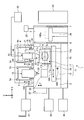
- FIG. 1 is a schematic diagram showing a three-dimensional laminating apparatus according to this embodiment.
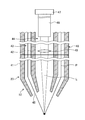
- FIG. 2 is a cross-sectional view showing an example of the tip of the laminated head.
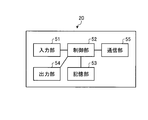
- FIG. 3 is a schematic diagram illustrating the configuration of the control device.
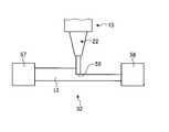
- FIG. 4 is a schematic diagram illustrating an example of an apparatus measurement unit.
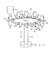
- FIG. 5 is a schematic diagram illustrating an example of a tool changer.
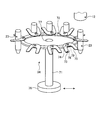
- FIG. 6 is a schematic diagram illustrating an example of a nozzle replacement unit.
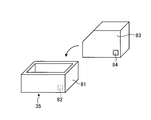
- FIG. 7A is a schematic diagram illustrating an example of a powder introduction unit.
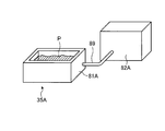
- FIG. 7B is a schematic diagram illustrating an example of a powder introduction unit.
- FIG. 8 is a schematic diagram illustrating an example of a powder recovery unit.
- FIG. 1 is a schematic diagram showing a three-dimensional laminating apparatus according to this embodiment.
- FIG. 2 is a cross-sectional view showing an example of the tip of the laminated head.
- FIG. 3 is a schematic diagram
- FIG. 9 is an explanatory diagram showing a method of manufacturing a three-dimensional shape by the three-dimensional laminating apparatus according to this embodiment.
- FIG. 10A is an explanatory diagram illustrating a method for manufacturing a three-dimensional object by the three-dimensional stacking apparatus according to the present embodiment.
- FIG. 10B is an explanatory diagram illustrating a method of manufacturing a three-dimensional shape by the three-dimensional stacking apparatus according to the present embodiment.
- FIG. 10C is an explanatory diagram illustrating a method for manufacturing a three-dimensional shape by the three-dimensional stacking apparatus according to the present embodiment.
- FIG. 11 is a flowchart showing a manufacturing process of a three-dimensional shape object by the three-dimensional stacking apparatus according to this embodiment.
- FIG. 10A is an explanatory diagram illustrating a method for manufacturing a three-dimensional object by the three-dimensional stacking apparatus according to the present embodiment.
- FIG. 10B is an explanatory diagram illustrating a method of manufacturing a three-dimensional shape by
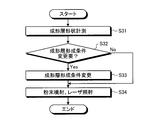
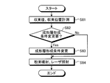
- FIG. 12 is a flowchart showing an example of a process of changing the forming layer forming conditions by the three-dimensional laminating apparatus according to this embodiment.
- FIG. 13 is a flowchart showing an example of a process for determining the processing conditions of the molded layer by the three-dimensional laminating apparatus according to the present embodiment.
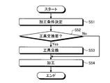
- FIG. 14 is a flowchart illustrating an example of a process of exchanging the tip of the machining unit by the three-dimensional laminating apparatus according to the present embodiment.
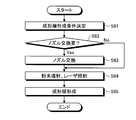
- FIG. 15 is a flowchart illustrating an example of a process of exchanging the tip of the stacking head by the three-dimensional stacking apparatus according to this embodiment.
- FIG. 16 is a flowchart showing an example of a powder identification process by the three-dimensional laminating apparatus according to this embodiment.
- FIG. 17 is a flowchart showing an example of a process of changing the forming layer forming conditions by the three-dimensional laminating apparatus according to the present embodiment.
- FIG. 1 is a schematic diagram showing a three-dimensional laminating apparatus 1 according to this embodiment.
- one direction in the horizontal plane is the X-axis direction
- the direction orthogonal to the X-axis direction is the direction orthogonal to the Y-axis direction, the X-axis direction, and the Y-axis direction (that is, the vertical direction).
- a three-dimensional laminating apparatus 1 shown in FIG. 1 is an apparatus for manufacturing a three-dimensional object on the base part 100.
- the base part 100 is a member that becomes a base on which a three-dimensional shaped object is formed, and is transported to a predetermined position by the three-dimensional laminating apparatus 1 to form a three-dimensional formed object on the surface.
- the base part 100 of this embodiment is a plate-shaped member.
- the base unit 100 is not limited to this.
- the base unit 100 may use a member that becomes a base of a three-dimensional shape object, or may use a member that adds a three-dimensional shape object.
- a member that becomes a part or product may be used as the base part 100 by forming a three-dimensional formed object at a predetermined position.
- the three-dimensional laminating apparatus 1 includes a three-dimensional laminating chamber 2, a spare chamber 3, a laminating head storage chamber 4, a machining unit storage chamber 5, a bed 10, a table unit 11, a laminating head 12, and machining.
- Unit 13 control device 20, shape measuring unit 30, heating head 31, device measuring unit 32, tool changing unit 33, nozzle changing unit 34, powder introducing unit 35, base moving unit 36 And an air discharge part 37, a gas introduction part 38, and a powder recovery part 39.
- the three-dimensional stacking chamber 2 is a casing (chamber) that is sealed from outside except for designed communication parts such as connected pipes.
- the designed communication part is provided with a valve or the like for switching between a sealed state and an open state, and the three-dimensional stacking chamber 2 can be sealed if necessary.
- the three-dimensional stacking chamber 2 includes a bed 10, a table unit 11, a stacking head 12, a part of the machining unit 13, a part of the heating head 31, a device measuring unit 32, a tool changing unit 33, A nozzle replacement part 34 is arranged inside.
- the preliminary chamber 3 is provided adjacent to the three-dimensional stacking chamber 2.
- the spare chamber 3 is sealed from the outside except for designed communication parts such as connected pipes.
- the preliminary chamber 3 is a decompression chamber that connects the outside and the three-dimensional stacking chamber 2.
- a base moving unit 36 is provided in the preliminary chamber 3.
- a door 6 having airtightness is provided at a connection portion of the three-dimensional stacking chamber 2.
- the preliminary chamber 3 is connected to the outside by a door 7 having airtightness.
- the spare chamber 3 is provided with an air discharge unit 25 that discharges air from the spare chamber 3.
- the preliminary chamber 3 can carry in a necessary member from the outside by opening the door 7.
- backup chamber 3 can carry in and carrying out a member between the three-dimensional lamination
- the stacking head storage chamber 4 is provided on the upper surface of the three-dimensional stacking chamber 2 in the Z-axis direction.
- the stacking head storage chamber 4 is supported by the Z-axis slide portion 4a so as to be movable in the Z-axis direction (the direction of the arrow 102) with respect to the three-dimensional stacking chamber 2.
- the laminated head storage chamber 4 has a lower surface in the Z-axis direction connected to the three-dimensional laminated chamber 2 by a bellows 18.
- the bellows 18 is connected to the lower surface in the Z-axis direction of the stacking head storage chamber 4 and the three-dimensional stacking chamber 2, and the lower surface of the stacking head storage chamber 4 in the Z-axis direction is a part of the three-dimensional stacking chamber 2. .
- the three-dimensional stacking chamber 2 has an opening formed in a region surrounded by the bellows 18.
- a space surrounded by the lower surface of the stacked head storage chamber 4 in the Z-axis direction and the bellows 18 is connected to the three-dimensional stacked chamber 2 and is sealed together with the three-dimensional stacked chamber 2.
- the laminated head storage chamber 4 supports the laminated head 12, the shape measuring unit 30, and the heating head 31.
- the stacking head storage chamber 4 includes a part including the nozzle 23 of the stacking head 12 and a part including the tip 24 of the heating head 31 from the lower surface in the Z-axis direction toward the three-dimensional stacking chamber 2. It protrudes.
- the laminated head storage chamber 4 moves in the Z-axis direction by the Z-axis slide part 4a, thereby moving the held laminated head 12, the shape measuring part 30, and the heating head 31 in the Z-axis direction. Further, since the laminated head storage chamber 4 is connected to the three-dimensional laminated chamber 2 via the bellows 18, the bellows 18 is deformed in accordance with the movement in the Z-axis direction, so that the three-dimensional laminated chamber 2 and the laminated head storage are accommodated. A sealed state with the chamber 4 can be maintained.
- the machining section storage chamber 5 is provided on the upper surface of the three-dimensional stacking chamber 2 in the Z-axis direction. Further, the machining section storage chamber 5 is disposed adjacent to the laminated head storage chamber 4. The machining section storage chamber 5 is supported by the Z-axis slide section 5a so as to be movable in the Z-axis direction (the direction of the arrow 104) with respect to the three-dimensional stacking chamber 2. The machined portion storage chamber 5 is connected to the three-dimensional stacking chamber 2 by a bellows 19 on the lower surface in the Z-axis direction.
- the bellows 19 connects the lower surface of the machining unit storage chamber 5 in the Z-axis direction and the three-dimensional stacking chamber 2, and the lower surface of the machining unit storage chamber 5 in the Z-axis direction of the three-dimensional stacking chamber 2.
- the three-dimensional stacking chamber 2 has an opening formed in a region surrounded by the bellows 19. A space surrounded by the Z-axis direction lower surface of the machined portion storage chamber 5 and the bellows 19 is connected to the three-dimensional stacking chamber 2 and sealed together with the three-dimensional stacking chamber 2.
- the machining unit storage chamber 5 supports the machining unit 13. Further, in the machining portion storage chamber 5, a part including the tool 22 of the machining portion 13 protrudes from the lower surface in the Z-axis direction toward the three-dimensional stacking chamber 2.
- the machining section storage chamber 5 moves in the Z-axis direction by moving the Z-axis slide section 5a in the Z-axis direction, thereby moving the held machining section 13 in the Z-axis direction. Further, since the machining section storage chamber 5 is connected to the three-dimensional stacking chamber 2 via the bellows 19, the bellows 19 is deformed in accordance with the movement in the Z-axis direction, and the three-dimensional stacking chamber 2 is machined. The sealed state with the part storage chamber 5 can be maintained.
- the bed 10 is provided at the bottom in the Z-axis direction in the three-dimensional stacking chamber 2.
- the bed 10 supports the table unit 11.
- the bed 10 is provided with various wirings, piping, and driving mechanisms.
- the table unit 11 is disposed on the upper surface of the bed 10 and supports the base unit 100.
- the table unit 11 includes a Y-axis slide unit 15, an X-axis slide unit 16, and a rotary table unit 17.
- the table part 11 attaches the base part 100 and moves the base part 100 on the bed 10.
- the Y-axis slide part 15 moves the X-axis slide part 16 with respect to the bed 10 along the Y-axis direction (the direction of the arrow 106).
- the X-axis slide unit 16 is fixed to a member that is an operation unit of the Y-axis slide unit 15, and the rotary table unit 17 is moved along the X-axis direction (the direction of the arrow 108) with respect to the Y-axis slide unit 15.
- Let The rotary table unit 17 is fixed to a member that is an operation unit of the X-axis slide unit 16 and supports the base unit 100.
- the rotary table unit 17 is, for example, an inclined circular table, and includes a fixed base 17a, a rotary table 17b, an inclined table 17c, and a rotary table 17d.
- the fixed base 17 a is fixed to a member that becomes an operating part of the X-axis slide part 16.
- the rotary table 17b is supported by the fixed base 17a, and rotates around the rotary shaft 110 parallel to the Z-axis direction.
- the tilt table 17c is supported by the rotary table 17b, and is rotated about the rotary shaft 112 orthogonal to the surface of the rotary table 17b.
- the rotary table 17d is supported by the tilt table 17c, and is rotated about a rotary shaft 114 orthogonal to the surface of the tilt table 17c that is supported.
- the rotary table 17d fixes the base unit 100.
- the rotary table unit 17 can rotate the base unit 100 around three orthogonal axes by rotating each unit around the rotation shafts 110, 112, and 114.
- the table unit 11 moves the base unit 100 fixed to the rotary table unit 17 in the Y-axis direction and the X-axis direction by the Y-axis slide unit 15 and the X-axis slide unit 16.
- the table part 11 rotates the base part 100 around three orthogonal axes by rotating each part around the rotation axes 110, 112, and 114 by the rotary table part 17.
- the table unit 11 may further move the base unit 100 along the Z-axis direction.
- the laminating head 12 injects a powder material toward the base part 100, further melts the powder by irradiating the injected powder material with laser light, and solidifies the molten powder on the base part 100.
- a molding layer is formed.
- the powder introduced into the lamination head 12 is a powder of a material that is a raw material for a three-dimensional shape.
- a metal material such as iron, copper, aluminum, or titanium can be used as the powder.
- the laminated head 12 is provided at a position facing the upper surface of the bed 10 in the Z-axis direction, and faces the table unit 11.
- the laminated head 12 is provided with a nozzle 23 at the bottom in the Z-axis direction. In the laminated head 12, the nozzle 23 is attached to the main body 46.
- FIG. 2 is a cross-sectional view showing an example of the nozzle 23 of the laminated head 12.
- the nozzle 23 is a double tube having an outer tube 41 and an inner tube 42 inserted into the outer tube 41.
- the outer tube 41 is a tubular member, and has a diameter that decreases toward the tip (lower side in the Z-axis direction).
- the inner tube 42 is inserted into the outer tube 41.
- the inner tube 42 is also a tubular member and has a shape whose diameter decreases toward the tip (lower side in the Z-axis direction).
- the nozzle 23 is a powder flow path 43 through which the powder material (powder) P passes between the inner periphery of the outer tube 41 and the outer periphery of the inner tube 42.
- the inner peripheral surface side of the inner tube 42 becomes a laser path 44 through which the laser light passes.
- the main body 46 to which the nozzle 23 is mounted is a double tube like the nozzle 23, and the powder flow path 43 and the laser path 44 are also formed in the same manner.
- the powder flow path 43 is disposed so as to surround the laser path 44.
- the powder flow path 43 becomes a powder injection part which injects powder.
- the powder P introduced from the powder introduction part 35 flows through the powder flow path 43 and is ejected from a nozzle ejection port part 45 which is an opening at an end between the outer tube 41 and the inner tube 42.
- the laminating head 12 injects the powder P so as to have a predetermined convergence diameter at a predetermined convergence position.
- the convergence diameter is the diameter of the locus of the powder P when the diameter of the locus of the injected powder P is minimized.
- the laminated head 12 injects the powder P so as to converge in the radial direction. That is, the lamination head 12 injects the powder P so that the locus of the powder P has a predetermined convergence diameter.
- the convergence position is a position where the trajectory of the injected powder P converges.
- the laminated head 12 includes a light source 47, an optical fiber 48, and a condensing unit 49.
- the light source 47 outputs laser light.
- the optical fiber 48 guides the laser output from the light source 47 to the laser path 44.
- the condensing unit 49 is disposed in the laser path 44 and is disposed in the optical path of the laser output from the optical fiber 48.
- the condensing unit 49 condenses the laser light L output from the optical fiber 48.
- the laser beam L condensed by the condenser 49 is output from the end of the inner tube 42.
- the light collecting portion 49 is disposed in the main body 46, but a part or all of the light collecting portion 46 may be disposed in the nozzle 23. When a part or all of the light condensing unit 46 is disposed on the nozzle 23, the focal position can be set to a different position by exchanging the nozzle 23.
- the laminating head 12 ejects the powder P from the powder flow path 43 and outputs the laser light L from the laser path 44.
- the powder P ejected from the lamination head 12 enters the region irradiated with the laser beam L output from the lamination head 12 and is heated by the laser beam L. After the powder P irradiated with the laser beam L is melted, it reaches the base 100.
- the powder P that has reached the base 100 in a molten state is cooled and solidified. Thereby, a molding layer is formed on the base part 100.
- the laminated head 12 of the present embodiment does not have to be an optical fiber that guides the laser light L output from the light source 47 by the optical fiber 48.
- the condensing part 49 may be provided on the main body 46, the nozzle 23, or both. Since the laminated head 12 of the present embodiment can be processed effectively, the powder flow path 43 for injecting the powder P and the laser path 44 for irradiating the laser light L are provided coaxially, but the present invention is not limited to this.
- the stacking head 12 may have a mechanism for spraying the powder P and a mechanism for irradiating the laser beam L as separate bodies.
- the laminated head 12 of the present embodiment irradiates the powder material with the laser beam. However, it is sufficient if the powder material can be dissolved or sintered, and may irradiate a light beam other than the laser beam.
- the machining unit 13 performs machining of a molded layer, for example.
- the machining portion 13 is provided at a position facing the upper surface of the bed 10 in the Z-axis direction, and faces the table portion 11.
- the machined portion 13 has a tool 22 attached to the lower portion in the Z-axis direction.
- the machining part 13 should just be provided in the movable range of the base part 100 by the table part 11 in the Z-axis direction upper side than the bed 10, and an arrangement position is not restricted to the position of this embodiment. .
- FIG. 3 is a schematic diagram showing the configuration of the control device 20.
- the control device 20 is electrically connected to each part of the three-dimensional laminating apparatus 1 and controls the operation of each part of the three-dimensional laminating apparatus 1.
- the control device 20 is installed outside the three-dimensional stacking chamber 2 and the spare chamber 3.
- the control device 20 includes an input unit 51, a control unit 52, a storage unit 53, an output unit 54, and a communication unit 55.
- storage part 53, the output part 54, and the communication part 55 is electrically connected.
- the input unit 51 is, for example, an operation panel.
- the worker inputs information, commands, and the like to the input unit 51.
- the control unit 52 is, for example, a CPU (Central Processing Unit) and a memory.
- the control unit 52 outputs a command for controlling the operation of each part of the three-dimensional laminating apparatus 1 to each part of the three-dimensional laminating apparatus 1.
- information from each unit of the three-dimensional laminating apparatus 1 is input to the control unit 52.
- the storage unit 53 is a storage device such as a RAM (Random Access Memory) or a ROM (Read Only Memory).
- the storage unit 53 stores an operation program of the three-dimensional laminating apparatus 1 that controls the operation of each unit by being executed by the control unit 52, information of the three-dimensional laminating apparatus 1, design information of a three-dimensional shape object, and the like. Is done.
- the output unit 54 is a display, for example.
- the output unit 54 displays information from each unit of the three-dimensional laminating apparatus 1, for example.
- the communication unit 55 communicates with a communication line such as the Internet or a LAN (Local Area Network) and exchanges information with the communication line.
- the control apparatus 20 should just have the control part 52 and the memory
- the shape measuring unit 30 is fixed to the stacked head storage chamber 4.
- the shape measuring unit 30 is disposed adjacent to the laminated head 12.
- the shape measuring unit 30 measures the surface shape of the molding layer formed on the base unit 100.
- a 3D scanner or a device that measures a relative distance can be used as the shape measuring unit 30.
- the shape measuring unit 30 scans (scans) a laser beam on the surface of the molding layer on the base unit 100, and calculates position information on the surface of the molding layer from the reflected light, thereby determining the surface shape of the molding layer. measure.
- the shape measuring unit 30 is attached to the laminated head storage chamber 4, but it is sufficient that the surface shape of the molding layer formed on the base unit 100 can be measured, and it is attached to another position. May be.
- the heating head 31 heats the molding layer on the base 100 or the molten powder P.
- the heating head 31 is fixed to the laminated head storage chamber 4.
- the heating head 31 is disposed adjacent to the laminated head 12.
- the heating head 31 irradiates laser light, infrared light, or electromagnetic waves, for example, and heats the molding layer or the melted powder P.
- the heating head 31 may further include, for example, a temperature sensor that measures the temperature of the surface of the molding layer, and may control heating based on the measurement result of the temperature sensor.
- the apparatus measurement unit 32 measures the position of the tip 56 of the tool 22 of the machining unit 13 as a machining unit measurement unit.
- FIG. 4 is a schematic diagram illustrating an example of the device measurement unit 32.
- the device measurement unit 32 includes a light source unit 57 and an imaging unit 58.
- the apparatus measurement unit 32 positions the tip 56 of the tool 22 of the machining unit 13 between the light source unit 57 and the imaging unit 58.
- the light source unit 57 is, for example, an LED.
- the imaging unit 58 is, for example, a CCD (Charge-Coupled Device) camera.
- the apparatus measurement unit 32 irradiates light from the light source unit 57 toward the imaging unit 58 in a state where the tip 56 of the tool 22 is disposed between the light source unit 57 and the imaging unit 58, and acquires an image by the imaging unit 58. To do. Thereby, an image in which light is blocked by the tip 56 of the tool 22 can be acquired.
- the device measurement unit 32 analyzes the image acquired by the imaging unit 58, and specifically detects the boundary between the position where the light is incident and the position where the light is not incident, thereby determining the shape and position of the tip 56. Can be acquired.
- the control device 20 Based on the acquired position of the tip 56 of the tool 22 and the position of the machining unit 13 (the position of the machining unit storage chamber 5), the control device 20 accurately determines the tip of the tool 22 attached to the machining unit 13. The correct position.
- the device measurement unit 32 is not limited to this configuration as long as it measures the position of the tip 56 of the machining unit 13, and may be measured by laser light, for example.
- the apparatus measuring unit 32 further measures a convergence position and a convergence diameter of the powder P ejected from the lamination head 12 as a powder supply unit measuring unit.
- the apparatus measurement unit 32 irradiates light from the light source unit 57 toward the imaging unit 58 with the stacked head 12 positioned so that the powder P converges between the light source unit 57 and the imaging unit 58.
- An image is acquired by the imaging unit 58. Therefore, the device measuring unit 32 can acquire an image in which light is blocked by the sprayed powder P.
- the device measurement unit 32 analyzes the image acquired by the imaging unit 58 and acquires the convergence position and the convergence diameter of the powder P.
- the apparatus measuring unit 32 measures the minimum diameter and the position of the minimum diameter of the injection region of the powder P from the acquired image by setting the portion where the light is blocked and the luminance is low as the region where the powder P is injected. By doing this, the convergence position and the convergence diameter of the powder P are acquired. Note that the device measurement unit 32 may acquire only one of the convergence position or the convergence diameter of the powder P.
- FIG. 5 is a schematic diagram illustrating an example of the tool changer 33. As shown in FIG. 5, the tool changer 33 includes a shaft part 61, a disk part 62, a plurality of holding parts 63, and a moving part 66.
- the shaft portion 61 is a shaft-shaped member, and rotates around, for example, the axial direction.
- the disc part 62 is a disc-shaped member.
- the disc part 62 has an opening 67 at the center.
- the disc part 62 is provided with a plurality of screw hole parts 68 on the outer edge at predetermined intervals along the circumferential direction.
- the disk portion 62 has an opening 67 fixed to the shaft portion 61. The disc part 62 rotates as the shaft part 61 rotates.
- a plurality of holding portions 63 are provided on the outer periphery of the disc portion 62 along the circumferential direction of the disc portion 62.
- the holding part 63 has a screw hole 69.
- the holding portion 63 is fixed to the disc portion 62 by screwing the screw hole portion 69 with the screw hole portion 68 of the disc portion 62 and tightening it with a bolt 64.
- the fixing method of the holding part 63 is not limited to this.
- the holding part 63 has a gripping part 65.
- the gripping portion 65 protrudes outward in the radial direction of the disc portion 62.
- the grip portion 65 has, for example, a shape having two projections, and can grip the tool 22 of the machining portion 13 between the two projections.
- the tool changer 33 holds a plurality of types of tools 22 having different sizes and processing to be held in the holder 63.
- the moving part 66 is attached to the shaft part 61.
- the moving part 66 moves the holding part 63 holding the tool 22 in the X-axis direction and the Y-axis direction by moving the shaft part 61 in the X-axis direction and the Y-axis direction.
- the moving part 66 moves the shaft part 61 to move the tool 22 held by the holding part 63 of the disk part 62 from a position facing the machining part 13 to a position that does not hinder the machining operation.
- the tool changer 33 moves the disc part 62 to a position facing the machining part 13 by the moving part 66. Thereafter, the tool changing unit 33 rotates the shaft unit 61 to move the gripping unit 65 that does not grip the tool 22 to a position facing the machining unit 13. Thereafter, the gripping unit 65 is moved by the moving unit 66, the gripping unit 65 is brought into contact with the tool 22 mounted on the machining unit 13, and the tool 22 is gripped by the gripping unit 65. In this state, a process of removing the tool 22 by the machining unit 13 is executed. Thereafter, the gripping portion 65 that grips another tool 22 to be mounted on the machining portion 13 is moved to a position facing the machining portion 13, and another tool 22 is attached to the machining portion 13.
- the tool changer 33 can replace the tool 22 of the machining part by attaching and detaching the tool 22 of the machining part 13.
- the tool changer 33 is not limited to this configuration as long as the tool 22 of the machining part can be changed.
- the nozzle replacement part 34 is arranged inside the three-dimensional stacking chamber 2.
- the nozzle replacement unit 34 replaces the nozzles 23 attached to the stacking head 12.
- FIG. 6 is a schematic diagram illustrating an example of the nozzle replacement unit 34.
- the nozzle replacement part 34 includes a shaft part 71, a disk part 72, a plurality of holding parts 73, and a moving part 76.
- the nozzle changing unit 34 has the same configuration as the tool changing unit 33 except that the nozzle 23 of the laminated head 12 is replaced instead of the tool 22 of the machining unit 13.
- the shaft part 71, the disk part 72, the holding part 73, the bolt 74, the gripping part 75, the moving part 76, the opening part 77, the screw hole part 78, and the screw hole part 79 of the nozzle replacement part 34 are each a tool. It corresponds to the shaft portion 61, the disc portion 62, the holding portion 63, the bolt 64, the gripping portion 65, the moving portion 66, the opening portion 67, the screw hole portion 68, and the screw hole portion 69 of the replacement portion 33. Therefore, the description of the nozzle replacement unit 34 is omitted.
- the powder introduction unit 35 introduces a powder material, which is a raw material for the three-dimensional shape, into the lamination head 12.
- FIG. 7A and FIG. 7B are schematic views showing examples of the powder introduction part.
- the powder P is managed in a state of being enclosed in a cartridge 83. That is, the powder is shipped in a cartridge 83 for each type of material, for example.
- the cartridge 83 is provided with a material display portion 84.
- the material display part 84 is a display which shows the information of powder, such as the kind of material, for example.
- the material display unit 84 is not limited to information that can be visually confirmed, and may be a display such as an IC chip, a two-dimensional code, or a mark that can acquire information by reading with a reader.
- the material display part 84 will not be restricted to these, if the kind of powder material can be shown.
- the material display unit 84 can show information on powder necessary for manufacturing a three-dimensional shape such as powder particle size, weight, purity, or oxide film.
- the material display part 84 may contain the information which shows whether powder is a regular product.
- the powder introduction unit 35 includes a powder storage unit 81 as a storage unit and a powder identification unit 82 as an identification unit.
- the powder storage unit 81 is a box-shaped member, for example, and stores the cartridge 83 therein.
- the powder storage unit 81 is connected to a conveyance air supply unit for carrying out the powder and a conveyance path for conveying the powder to the lamination head 12.
- the powder storage unit 81 introduces the powder stored in the cartridge 83 to the stacking head 12.
- the powder identification unit 82 detects that the cartridge 83 is stored in the powder storage unit 81, the powder identification unit 82 reads the material display unit 84 of the cartridge 83 and reads information on the powder stored in the cartridge 83.
- the powder introduction unit 35 can supply known powder to the stacking head 12 by acquiring powder information by the powder identification unit 82.
- the powder introduction unit 35 may supply powder that is not managed in a state of being enclosed in the cartridge 83 to the stacking head 12.
- FIG. 7B shows the powder introduction portion 35A when the powder is not sealed in the cartridge.
- the powder introduction unit 35A includes a powder storage unit 81A, a powder identification unit 82A, and a powder guide tube 89 that connects the powder storage unit 81A and the powder identification unit 82A.
- the powder storage unit 81A is, for example, a box-shaped member, and stores the powder P therein.
- the powder identification unit 82A analyzes the powder supplied via the powder guide tube 89, and the powder necessary for manufacturing the three-dimensional shape product such as the type, particle size, weight, purity, or oxide coating of the powder. Measure information.
- the powder identification unit 82A As the powder identification unit 82A, a spectroscopic analyzer that identifies a powder material by spectroscopic analysis, a particle size analyzer that measures the particle size of powder by particle size analysis, a weigh scale that measures the weight of powder, or the like can be used.
- the powder identification unit 82A measures the purity of the powder from, for example, the type, particle size, and weight of the measured powder material.
- the powder identification part 82A measures the powder oxide film by, for example, conductivity.
- the powder introduction unit 35 ⁇ / b> A can also supply known powder to the stacking head 12 by acquiring powder information by the powder identification unit 82 ⁇ / b> A.
- the base moving part 36 is arranged in the spare room 3.
- the base moving unit 36 moves the base unit 100 a from the preliminary chamber 3 into the three-dimensional stacked chamber 2, and moves the base unit 100 in the three-dimensional stacked chamber 2 into the preliminary chamber 3.
- the base moving part 36 is attached with a base part 100a carried into the spare chamber 3 from the outside.
- the base moving part 36 carries the attached base part 100a from the preliminary chamber 3 into the three-dimensional stacking chamber 2. More specifically, the base moving part 36 moves the base part 100 a attached to the base moving part 36 into the three-dimensional stacking chamber 2 and attaches it to the rotary table part 17.
- the base moving unit 36 moves the base unit 100 using, for example, a robot arm or an orthogonal axis transfer device.
- the air discharge unit 37 is, for example, a vacuum pump, and discharges air in the three-dimensional stacking chamber 2.
- the gas introduction unit 38 introduces a predetermined component gas, for example, an inert gas such as argon or nitrogen, into the three-dimensional stacking chamber 2.
- the three-dimensional stacking apparatus 1 discharges air from the three-dimensional stacking chamber 2 through the air discharge unit 37 and introduces gas into the three-dimensional stacking chamber 2 through the gas introduction unit 38.
- the three-dimensional laminating apparatus 1 can make the inside of the three-dimensional laminating chamber 2 a desired gas atmosphere.
- the gas introduction part 38 is provided below the air discharge part 37 in the Z-axis direction.
- the three-dimensional laminating apparatus 1 When the three-dimensional laminating apparatus 1 is used as a gas for introducing argon having a higher specific gravity than a gas such as oxygen in the air by providing the gas introduction part 38 below the air discharge part 37 in the Z-axis direction,
- the original stacking chamber 2 can be suitably filled with argon gas.
- positioning of piping when making the gas introduced into a gas lighter than air.
- the powder collection unit 39 collects the powder P that has been ejected from the nozzle ejection port 45 of the stacking head 12 and that has not formed the molding layer.
- the powder recovery unit 39 sucks the gas in the three-dimensional stacking chamber 2 and recovers the powder P contained in the gas.
- the powder P sprayed from the lamination head 12 is melted and solidified by the laser light L to form a molding layer.
- a part of the powder P may remain in the three-dimensional stacking chamber 2 as it is, for example, when the laser beam L is not irradiated.
- the chips cut by the machining unit 13 and discharged from the molding layer remain in the three-dimensional stacking chamber 2.
- the powder recovery unit 39 recovers the powder P and chips remaining in the three-dimensional stacking chamber 2.
- the powder recovery unit 39 may include a mechanism for mechanically recovering powder such as a brush.
- FIG. 8 is a schematic diagram showing an example of the powder recovery unit 39.
- the powder recovery unit 39 includes an introduction unit 85, a cyclone unit 86, a gas discharge unit 87, and a powder discharge unit 88.
- the introduction portion 85 is, for example, a tubular member, and one end portion is connected to, for example, the three-dimensional stacking chamber 2.
- the cyclone portion 86 is, for example, a hollow frustoconical member, and its diameter decreases, for example, downward in the vertical direction.
- the other end of the introduction part 85 is connected to the cyclone part 86 along the tangential direction of the outer periphery of the cyclone part 86.
- the gas discharge part 87 is a tubular member, and one end part is connected to the upper end part of the cyclone part 86 in the vertical direction.
- the powder discharge portion 88 is a tubular member, and one end portion is connected to the end portion of the cyclone portion 86 on the lower side in the vertical direction.
- a pump for sucking gas is connected to the other end of the gas discharge part 87. Therefore, the gas discharge part 87 draws gas from the cyclone part 86, and makes the cyclone part 86 into a negative pressure. Since the cyclone portion 86 has a negative pressure, the introduction portion 85 sucks gas from the three-dimensional stacking chamber 2. The introduction part 85 sucks the powder P that has not formed the molding layer together with the gas in the three-dimensional stacking chamber 2. The introduction part 85 is connected to the cyclone part 86 along the tangential direction of the outer periphery of the cyclone part 86. Accordingly, the gas and the powder P sucked into the introduction part 85 swirl along the inner periphery of the cyclone part 86.
- the powder P Since the specific gravity of the powder P is higher than that of the gas, the powder P is centrifuged outward in the radial direction of the inner periphery of the cyclone portion 86.
- the powder P is discharged from the powder discharge unit 88 toward the powder discharge unit 88 below the stretching direction by its own weight. Further, the gas is discharged by the gas discharge unit 87.
- the powder collection unit 39 collects the powder P that has not formed the molding layer in this way.
- recovery part 39 in this embodiment may divide
- recovery part 39 will not be restricted to such a structure, if the powder P which did not form a shaping
- FIG. 9 is a schematic diagram showing a method for manufacturing a three-dimensional object by the three-dimensional laminating apparatus 1 according to this embodiment. Further, the manufacturing method shown in FIG. 9 can be executed by the control device 20 controlling the operation of each part.
- the pedestal 91 is, for example, a metal plate-like member, but the shape and material are arbitrary as long as a three-dimensional shape is manufactured on the top.
- the pedestal 91 is attached on the base part 100.
- the base unit 100 is fixed to the rotary table unit 17 of the table unit 11 together with the base 91.
- the pedestal 91 can also be used as the base part 100.
- the control device 20 moves the base unit 100 by the table unit 11 so that the pedestal 91 on the base unit 100 is arranged below the stacked head 12 in the Z-axis direction, as shown in step S1.
- step S ⁇ b> 2 the control device 20 introduces the powder from the powder introduction unit 35 to the lamination head 12, and irradiates the laser beam L while injecting the powder P together with the gas from the lamination head 12.
- the powder P is sprayed toward the base 91 on the base 100 with a predetermined convergence diameter.
- the laser beam L is applied to the powder P with a predetermined spot diameter between the laminated head 12 and the pedestal 91.
- the spot diameter in the Z-axis direction of the spot diameter of the laser beam L with respect to the position in the Z-axis direction of the convergence diameter of the powder P and the spot diameter at the position in the Z-axis direction of the convergence diameter of the powder P are, for example, condensing It can be controlled by moving the position of the portion 49.
- the control device 20 sprays the powder P while irradiating the laser beam L with the stacking head 12, so that the powder P is melted by the irradiation with the laser beam L as shown in step S3.
- the melted powder P falls as a melt A downward toward the pedestal 91 on the base part 100 in the Z-axis direction.
- the melt A that has fallen downward in the Z-axis direction reaches a predetermined position of the base 91 on the base 100.
- the melt A on the pedestal 91 is cooled, for example, by being allowed to cool at a predetermined position on the pedestal 91.
- the cooled melt A is solidified as a solidified body B on the pedestal 91 as shown in step S4.
- the control device 20 forms the solidified body B on the base unit 100 by the stacking head 12 according to the procedure shown in steps S2 to S4 while moving the base unit 100 on the base unit 100 to a predetermined position.
- the solidified body B forms a molding layer 92 having a predetermined shape on the pedestal 91 as shown in step S5.
- step S ⁇ b> 6 the control device 20 moves the base 91 of the base portion 100 by the table portion 11 so that the molding layer 92 formed on the base 91 is disposed below the machining portion 13 in the Z-axis direction. Move. Further, the control device 20 performs machining on the molded layer 92 by the machining unit 13. The control device 20 selects whether or not the machining by the machining unit 13 is performed, and may not be performed if unnecessary. Therefore, the machining shown in step S6 may not be performed depending on the command of the control device 20.
- step S ⁇ b> 7 the control device 20 causes the table portion 11 to place the pedestal of the base portion 100 so that the molding layer 92 formed on the pedestal 91 is disposed below the laminated head 12 in the Z-axis direction. 91 is moved. And the procedure shown to step S2 to step S6 is repeated, the shaping
- the three-dimensional laminating apparatus 1 produces a three-dimensional object as follows.
- the powder injection unit 43 of the stacking head 12 injects the powder P toward the base 91 on the base unit 100. Further, the inner tube 42 of the laminated head 12 irradiates the powder P with the laser light L between the laminated head 12 and the pedestal 91. The powder P irradiated with the laser light L is melted and solidified on a pedestal 91 on the base part 100 to form a molding layer 92.
- the three-dimensional laminating apparatus 1 sequentially laminates the molding layer 93 on the molding layer 92, and applies appropriate machining to the molding layers 92, 93 by the machining unit 13 to produce a three-dimensional shape product.
- the three-dimensional shape is manufactured on the pedestal 91, but the three-dimensional shape may not be manufactured on the pedestal 91.
- the three-dimensional shape may be manufactured directly on the base 100, for example.
- the three-dimensional laminating apparatus 1 may perform what is called build-up welding by laminating a molding layer on an existing modeled object.
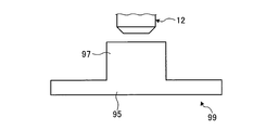
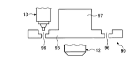
- FIG. 10A to FIG. 10C are schematic views showing a method for manufacturing a three-dimensional object by the three-dimensional laminating apparatus 1 according to this embodiment. 10A to 10C show a procedure in which the three-dimensional laminating apparatus 1 manufactures the member 99 shown in FIG. 10C.
- the member 99 has a disk portion 95, a shaft portion 97, and a truncated cone portion 98.
- the member 99 has a screw hole 96 formed in the disk portion 95.
- the disc portion 95 is a disc-shaped member.
- the shaft portion 97 is a shaft-shaped member having a diameter smaller than that of the disc portion 95 and extends from the central portion of one surface of the disc portion 95.
- the screw hole portion 96 is provided outside the shaft portion 97 of the disc portion 95.
- the truncated cone part 98 is provided at the tip of the shaft part 97, and its outer diameter increases in the direction opposite to the disk part 95.
- the major axis of the truncated cone part 98 is, for example, the same size as the outer diameter of the disk part 95. That is, the screw hole portion 96 is located inside the major axis of the truncated cone portion 98.
- the three-dimensional laminating apparatus 1 forms a disk portion 95 and a shaft portion 97 by laminating molded layers by the laminating head 12.
- the threaded part 96 is formed by the machining part 13.
- the three-dimensional laminating apparatus 1 forms the truncated cone part 98 on the shaft part 97 by laminating the molding layer by the laminating head 12 after forming the screw hole part 96.
- the member 99 is manufactured in this way.
- the long diameter portion of the truncated cone portion 98 is located outside the screw hole portion 96.
- the screw hole portion 96 is covered with the truncated cone portion 98 at the top. Therefore, for example, when the member 99 is manufactured by machining, the processing tool of the screw hole portion 96 cannot be moved from the upper portion of the truncated cone portion 98 toward the disc portion 95.
- the three-dimensional laminating apparatus 1 forms the screw hole portion 96 before the truncated cone portion 98 is manufactured. In this case, the upper part of the screw hole 96 is not covered.
- the three-dimensional laminating apparatus 1 can process the screw hole portion 96 by moving the machining portion 13 from the upper portion in the Z-axis direction along the Z-axis direction.
- the machining unit 13 can facilitate machining by adjusting the timing of forming the molding layer and machining.
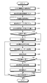
- FIG. 11 is a flowchart illustrating a manufacturing process of a three-dimensional shape by the three-dimensional stacking apparatus 1 according to the present embodiment.
- the control device 20 reads design information of a three-dimensional shape object stored in the storage unit 53.
- the control device 20 discharges the air in the three-dimensional stacking chamber 2 by the air discharge unit 37 (step S11).
- the three-dimensional stacking chamber 2 has a door 6 closed and is separated from the preliminary chamber 3. Further, the three-dimensional stacking chamber 2 is also closed and sealed at a portion communicating with other outside air.
- the control device 20 discharges air by the air discharge unit 37 so that the oxygen concentration in the three-dimensional stacked chamber 2 is 100 ppm or less, preferably 10 ppm or less.
- the control device 20 can be in an inactive state when the oxygen concentration in the three-dimensional stacking chamber 2 is 100 ppm or less, and can be more reliably in an inactive state by being 10 ppm or less.
- step S12 the base part 100 having the base 91 is attached to the base moving part 36 in the preliminary chamber 3 (step S12).
- the three-dimensional laminating apparatus 1 may perform the process of step S12 prior to the process of step S11.
- the control device 20 closes the door 7 of the spare room 3, and discharges the air in the spare room 3 by the air discharge part 25 (step S13).
- the control device 20 reduces the oxygen concentration in the preliminary chamber 3 by discharging air from the air discharge unit 25.
- the oxygen concentration in the preliminary chamber 3 is preferably the same as that in the three-dimensional stacked chamber 2, for example.
- the control device 20 opens the door 6 of the three-dimensional stacking chamber 2, and the base moving unit 36 moves the base unit 100 to the rotary table unit 17 in the three-dimensional stacking chamber 2. Attach (step S14).
- the base unit 100 is fixed to the rotary table unit 17.
- the control device 20 returns the base moving unit 36 into the spare chamber 3 and closes the door 6.
- the gas introduction unit 38 introduces gas into the three-dimensional stacking chamber 2 (step S15).
- the gas introduced by the gas introduction unit 38 is an inert gas such as nitrogen or argon.
- the gas introduction unit 38 introduces an inert gas so that the residual oxygen concentration in the three-dimensional stacking chamber 2 is 100 ppm or less.
- the three-dimensional laminating apparatus 1 may omit step S11, step S13, and step S15 depending on the type of powder material. For example, when the quality of the three-dimensional shape does not become a problem even when the powder material is oxidized, these steps may be omitted, and the three-dimensional stacking chamber 2 and the preparatory chamber 3 may be set to an air atmosphere. Moreover, step S13 and step S15 may be performed continuously also after step S16. That is, the air discharge unit 37 may appropriately discharge air from the three-dimensional stacking chamber 2 while manufacturing the three-dimensional shape. Further, the gas introduction unit 38 may appropriately introduce an inert gas into the three-dimensional stacking chamber 2 while manufacturing the three-dimensional object.
- the control device 20 determines whether to machine the pedestal 91 on the base unit 100 (step S16). For example, the control device 20 causes the shape measuring unit 30 to measure the surface shape of the pedestal 91. The control device 20 determines whether to machine the pedestal 91 based on the measurement result of the shape measuring unit 30. For example, when the surface roughness of the pedestal 91 is larger than a predetermined value, the control device 20 determines to machine the pedestal 91.
- the necessity determination of the machining of the pedestal 91 by the control device 20 is not limited to this, and may not be based on the measurement result of the shape measuring unit 30.
- control device 20 may store information on the pedestal 91 in the storage unit 53, and determine whether or not the pedestal 91 needs to be processed from the information on the pedestal 91 and the design information of the three-dimensional shape object. Moreover, the control apparatus 20 is good also as the setting which always processes the base 91. FIG.
- the control device 20 determines that machining of the pedestal 91 is necessary (Yes in step S16), the machining unit 13 performs machining of the pedestal 91 under predetermined conditions (step S17).
- the control device 20 determines the machining conditions of the pedestal 91 based on, for example, the shape measurement result of the pedestal 91 by the shape measuring unit 30 or the information on the pedestal 91 and the design information of the three-dimensional shape.
- the formation condition of the molding layer is determined (step S18).
- the forming conditions of the forming layer include, for example, the shape of each layer of the forming layer, the type of powder P, the spraying speed of the powder P, the spraying pressure of the powder P, the irradiation condition of the laser light L, the convergent diameter of the powder P and the laser light L.
- the positional relationship between the spot diameter and the surface of the molding layer, the size of the powder P melted in the air, the temperature, the size of the molten pool formed on the surface of the molding layer being formed, the cooling rate, or the base portion by the table portion 11 are necessary conditions for forming the molding layer, such as a moving speed of 100.
- the control device 20 sprays the powder P toward the pedestal 91 on the base portion 100 by the lamination head 12, and starts the irradiation with the laser light L (step S19).
- the control device 20 can melt the powder P with the laser light L by irradiating the laser light L while injecting the powder P, and solidify the melted powder P. Form.
- the control device 20 irradiates the laser beam L while injecting the powder P, and moves the base portion 100 by the table portion 11 to form the molding layer 92 on the pedestal 91 (step S20).
- the control device 20 may heat the molding layer 92 with the heating head 31 or heat a portion before the solidified body B adheres.
- the control device 20 determines whether the molding layer 92 needs to be machined (step S21). For example, the control device 20 causes the shape measuring unit 30 to measure the surface shape of the molding layer 92. The control device 20 determines whether machining of the molding layer 92 is necessary based on the measurement result of the shape measuring unit 30. For example, the control device 20 determines that the molding layer 92 is to be machined when the surface roughness of the molding layer 92 is larger than a predetermined value. However, the criteria for determining whether machining of the molded layer 92 is necessary are not limited to this.
- the control device 20 may determine whether or not the molding layer 92 needs to be machined based on the design information of the three-dimensional shape and the formation conditions of the molding layer. For example, when the surface roughness of the molding layer 92 calculated from the molding layer forming conditions is larger than the necessary surface roughness based on the design information of the three-dimensional shape, the control device 20 needs to machine the molding layer 92. You may make it judge that it is.
- step S21 When the control device 20 determines that machining of the molded layer 92 is not necessary (No in step S21), the control device 20 proceeds to step S24.
- the control device 20 determines machining conditions for the molding layer 92 (step S22). For example, the control device 20 determines the processing condition based on the measurement result of the shape measuring unit 30 or the design information of the three-dimensional shape object and the formation condition of the molding layer 92. After determining the molding layer processing conditions, the control device 20 causes the machining unit 13 to machine the molding layer 92 based on the determined processing conditions (step S23).
- control device 20 When the control device 20 performs machining of the molding layer 92 or determines that the machining of the molding layer 92 is not necessary, is it necessary to further stack the molding layer 93 on the molding layer 92? Is determined (step S24). For example, the control device 20 determines whether it is necessary to further stack the molding layer 93 on the molding layer 92 based on the design information of the three-dimensional shape read from the storage unit 53.
- Step S24 When it is determined that the molding layer 93 needs to be stacked (Yes in Step S24), the control device 20 returns to Step S18 and stacks the molding layer 93 on the molding layer 92. When the control device 20 determines that the formation of the molding layer 93 is unnecessary (No in step S24), the manufacture of the three-dimensional shape is completed.
- the three-dimensional laminating apparatus 1 manufactures a three-dimensional shape in this way.
- the three-dimensional laminating apparatus 1 according to the present embodiment produces a three-dimensional shape by injecting the powder P by the laminating head 12 and irradiating the powder P with the laser light L.
- the three-dimensional laminating apparatus 1 can appropriately perform machining on the molding layer 92 by the machining unit 13. Therefore, the three-dimensional laminating apparatus 1 can manufacture a three-dimensional shape with high accuracy.
- the base moving unit 36 moves the base unit 100 into the three-dimensional stacking chamber 2. Air may be exhausted inside the three-dimensional stacking chamber 2.
- the base moving unit 36 can move the base unit 100 to the inside of the three-dimensional stacking chamber 2 without, for example, an operator entering the three-dimensional stacking chamber 2.
- FIG. 12 is a flowchart showing an example of a process of changing the forming layer forming conditions by the three-dimensional laminating apparatus 1 according to this embodiment.
- the control apparatus 20 measures the shape of the molding layer 92 by the shape measurement part 30 (step S31).
- the control device 20 may cause the shape measuring unit 30 to measure the shape of the molding layer 92 while forming the molding layer on the laminated head 12.
- the shape measuring unit 30 can measure both the shape of the portion where the laminated head 12 is to form the solidified body B and the shape of the solidified body B formed at that portion. That is, the shape measuring unit 30 can measure the surface shape before and after the formation of the molding layer 92.
- the control device 20 determines whether it is necessary to change the molding layer formation condition based on the measurement result of the shape measuring unit 30 (step S32).
- the control device 20 determines, for example, whether to change the distance between the location and the laminated head 12 based on the measurement result of the surface shape of the location where the laminated head 12 is to form the solidified body B. For example, when the surface shape of the location where the laminated head 12 is to form the solidified body B is different from the surface shape of other locations, the control device 20 determines the distance between the location where the molding layer is formed and the laminated head 12. The position of the laminated head 12 is changed so as to be constant.
- control device 20 determines whether to change, for example, the injection condition of the powder P or the irradiation condition of the laser beam L based on the measurement result of the shape of the formed solidified body B. For example, when the shape of the formed solid body B is unsuitable as compared with the design information of the three-dimensional shape, the control device 20 appropriately sets the injection condition of the powder P or the irradiation condition of the laser beam L, etc. To change.
- control device 20 determines that the forming layer forming condition needs to be changed (Yes in step S32), the control device 20 changes the forming layer forming condition (step S33).
- the control device 20 causes the stacking head 12 to eject the powder P and the laser beam L.
- the molded layer is formed by moving the base part 100 with the table part 11 while performing the irradiation of (Step S34).
- Step S34 the process of changing the forming conditions of the molding layer by the shape measuring unit 30 is completed.
- the control device 20 changes and determines the formation condition of the molding layer according to the measurement result of the surface shape of the molding layer by the shape measuring unit 30, and controls the operation of the stacking head 12. Therefore, as described above, the three-dimensional laminating apparatus 1 can more appropriately form the molding layer, for example, by making the distance between the portion where the molding layer is formed and the lamination head 12 constant. Furthermore, the three-dimensional laminating apparatus 1 can measure the shape of the molding layer 92 by the shape measuring unit 30 while forming the molding layer by the lamination head 12. Therefore, the three-dimensional laminating apparatus 1 can make the forming layer forming conditions more appropriate, and can manufacture a three-dimensional shape with higher accuracy.
- FIG. 13 is a flowchart showing an example of a process for determining the processing conditions of the molded layer by the three-dimensional laminating apparatus 1 according to the present embodiment.
- the control apparatus 20 measures the shape of the molding layer 92 by the shape measurement part 30 (step S41).
- the control device 20 determines whether machining is necessary for the molding layer 92 based on the measurement result of the shape measuring unit 30 (step S42).
- the device measurement unit 32 measures the position of the tip 56 of the tool 22 of the machining unit 13 (step S43). ).
- the control device 20 determines the processing conditions of the molding layer 92 from the shape measurement of the molding layer 92 by the shape measurement unit 30 and the measurement result of the position of the tip 56 of the machining unit 13 by the device measurement unit 32 (step S44). Note that the control device 20 determines the processing conditions of the molding layer 92 based on either the shape of the molding layer 92 by the shape measuring unit 30 or the measurement result of the position of the tip 56 of the machining unit 13 by the device measuring unit 32. May be determined. The control device 20 determines the amount to be processed by the machining unit 13 based on the shape of the molding layer 92 by the shape measuring unit 30. The control device 20 determines the trajectory of movement of the machining unit 13 in the Z-axis direction and the trajectory of movement of the base unit 100 by the table unit 11 by determining the machining amount.
- step S45 the control device 20 mechanically processes the molded layer 92 by the machining unit 13 (step S45), and ends this process. Moreover, this process is complete
- control device 20 determines the cutting condition of the molding layer according to the measurement result of the surface shape of the molding layer 92 by the shape measurement unit 30 and the measurement result of the tip 56 of the machining unit 13 by the device measurement unit 32. And control the operation of the machined portion 13. Therefore, the three-dimensional laminating apparatus 1 can appropriately calculate the machining conditions of the molding layer 92 and perform the machining of the molding layer 92 appropriately.
- the device measuring unit 32 measures the position of the tip 56 of the tool 22 of the machining unit 13 by imaging. Therefore, the device measuring unit 32 can measure the position of the tip while operating the machining unit 13, and also includes the position change of the tip 56 of the tool 22 of the machining unit 13 due to thermal expansion. The position can be measured. For example, when the error in the measurement result of the position of the tip 56 of the tool 22 of the machining unit 13 is larger than the necessary machining allowance of the molding layer 92, the molding layer 92 is processed even if the molding layer 92 is machined. May not be machined or the machining allowance may be too large. However, since the three-dimensional laminating apparatus 1 according to the present embodiment can suppress the measurement error of the position of the tip 56 of the machining unit 13 by the apparatus measurement unit 32, the molding layer 92 is more appropriately machined. be able to.
- the thickness of the actually formed molding layer 92 in the Z-axis direction is In some cases, the maximum error may be 0.2 mm, for example, a thickness of 0.1 mm to 0.3 mm. Further, the position of the tip 56 of the tool 22 changes due to thermal expansion, and the error in the position change of the tip 56 of the tool 22 due to thermal expansion may be 0.1 mm at the maximum, for example.
- the control device 20 determines the thickness of the molding layer 92 and the tool 22. In consideration of the maximum error with respect to the position change, it is necessary to instruct the machining unit 13 to perform removal processing with a machining allowance of 0.3 mm or more.
- the thickness of the molding layer 92 is 0.2 mm
- the machining allowance is 0.3 mm or more, all of the molding layer 92 including the normal part is removed, and further, the molding layer below the molding layer 92 is removed. There is a possibility of being processed.
- the shape measuring unit 30 and the device measuring unit 32 are used for the tool 22 due to the actual thickness and thermal expansion of the forming layer 92.
- the position change of can be measured. Therefore, the control device 20 does not need to consider the maximum error between the thickness of the molding layer 92 and the position change of the tool 22, and the machining unit 13 appropriately removes only the surface of the molding layer 92 in which the formation defect has occurred. Can be processed.
- FIG. 14 is a flowchart illustrating an example of a process for replacing the tool 22 of the machining unit 13 by the three-dimensional laminating apparatus 1 according to the present embodiment.
- the control device 20 determines the machining conditions for machining the molding layer 92 (step S51).
- the determination of the processing conditions in step S51 is performed, for example, by the same method as the determination of the processing conditions in step S44 of FIG.
- the control device 20 determines whether to replace the tool 22 of the machining unit 13 based on the determined processing conditions of the molding layer 92 (step S52). For example, when the control device 20 determines that the forming layer 92 needs to be processed with higher accuracy, the control device 20 needs to replace the tool 22 of the machining unit 13 with one having a smaller blade. Judge that there is. For example, when changing the machining content, the control device 20 determines that the tool 22 of the machining unit 13 needs to be replaced. For example, when processing the surface of the forming layer 92 by the machining unit 13 and then processing the screw hole or the like in the forming layer 92, the control device 20 uses the tool for surface processing from the tool 22 for the surface processing. Therefore, it is determined that it is necessary to replace the tool for threaded hole machining.
- the conditions for determining whether to replace the tool 22 of the machining unit 13 are not limited to these.
- step S52 When the control device 20 determines that the tool 22 of the machining unit 13 is to be replaced (Yes in step S52), the tool replacement unit 33 replaces the tool 22 of the machining unit 13 (step S53).
- step S54 When the control device 20 replaces the tool 22 of the machining unit 13, the control unit 20 performs machining of the molding layer 92 by the machining unit 13 with the replaced tool (step S54), and ends this process. Further, when it is determined that the tool 22 of the machining unit 13 does not need to be replaced (No in step S52), the control device 20 performs machining of the molding layer 92 by the machining unit 13 that has not replaced the tool. (Step S54), this process ends.
- the tool changer 33 can change the tool 22 of the machined part 13 based on the determined processing conditions of the molding layer 92. Therefore, the three-dimensional laminating apparatus 1 according to the present embodiment can perform the machining of the molding layer 92 more appropriately or more easily.
- FIG. 15 is a flowchart illustrating an example of a process of replacing the nozzles 23 of the stacking head 12 by the three-dimensional stacking apparatus 1 according to the present embodiment.
- the control apparatus 20 determines the formation conditions of the molding layer 92 (step S61). The determination of the processing conditions in step S61 is performed, for example, by the same method as the determination of the formation conditions of the molding layer 92 in step S18 of FIG.
- the control device 20 determines whether to replace the nozzles 23 of the stacking head 12 based on the determined formation conditions of the molding layer 92 (step S62).
- the control device 20 emits a laser beam L having a smaller spot diameter from the tool 22 of the machined portion 13 when, for example, the determined forming conditions of the forming layer 92 increase the forming accuracy of the forming layer 92. Or, it is determined that it is necessary to replace the powder P with a smaller one for converging the diameter of the injection of the powder P.
- the condition for determining whether to replace the nozzle 23 of the laminated head 12 is not limited to this.
- step S62 When it is judged that the nozzle 23 of the lamination
- the control device 20 ejects the powder P and irradiates the laser beam L with the stacking head 12 whose nozzle 23 is replaced (step S64), and forms a molding layer (step S64). S65), this process is finished.
- the control device 20 performs the injection of the powder P and the irradiation of the laser light L by the laminated head 12 whose nozzle is not replaced. (Step S64), a molding layer is formed (Step S65), and this process is terminated.
- the three-dimensional laminating apparatus 1 can replace the nozzles 23 of the laminating head 12 based on the forming conditions of the molding layer 92 determined by the nozzle exchanging unit 34. Therefore, the three-dimensional laminating apparatus 1 according to this embodiment can perform the formation of the molding layer 92 more appropriately or more easily.
- FIG. 16 is a flowchart showing an example of a powder identification process by the three-dimensional laminating apparatus 1 according to this embodiment.
- the control device 20 detects that the powder has been set in the powder introduction unit 35 (step S71). For example, it detects that the cartridge 83 containing the powder is stored in the powder storage unit 81.
- the control device 20 identifies the powder from the powder identification unit 82 of the powder introduction unit 35 (step S72).
- the control device 20 reads the material display unit 84 of the cartridge 83 from the powder identification unit 82 of the powder introduction unit 35, for example, and manufactures a three-dimensional shape product such as powder type, particle size, weight, purity, or oxide coating.
- the necessary powder information is detected above.
- the control device 20 may identify the powder in the powder introduction unit 35A by the powder identification unit 82A of the powder introduction unit 35A.
- the control device 20 determines whether the powder in the powder introduction unit 35 is appropriate based on the powder identification result (step S73). For example, the control device 20 determines whether the powder in the powder introduction unit 35 is appropriate based on design information of the three-dimensional shape. For example, when the powder in the powder introduction unit 35 is an inappropriate material for producing a three-dimensional shape product to be produced, the control device 20 determines that the powder in the powder introduction unit 35 is not appropriate. to decide.
- the powder introduction unit 35 introduces the powder into the lamination head 12 (Step S74).
- the control device 20 determines the formation conditions of the molding layer 92 based on the powder information identified in step S72 (step S75), and ends this process.
- the lamination head 12 may mix and inject different powders, for example.
- the control apparatus 20 determines the formation conditions of the shaping
- the forming conditions of the molding layer 92 are the same as those in step S18 of FIG.
- the shape of each layer of the molding layer, the type of powder, the spraying speed of the powder P, the spraying pressure of the powder P, and the laser Conditions necessary for forming the molding layer such as the irradiation conditions of the light L, the temperature of the melt A, the cooling temperature of the solidified body B, or the moving speed of the base part 100 by the table part 11.
- control device 20 determines that the powder is not appropriate (No in Step S73) (No) (No) (No) (No), the control unit 20 transmits information indicating that the powder is not appropriate or information on the inappropriate powder to the external data via the communication unit 55. This is transmitted to the server or the like (step S76), and this process is terminated. In this case, the control device 20 ends this process without issuing a powder introduction command from the powder introduction unit 35 to the stacking head 12. That is, the three-dimensional laminating apparatus 1 stops supplying the powder to the laminating head 12 when determining that the powder is not appropriate.
- the control device 20 controls the introduction of the powder from the powder introduction unit 35 to the stacking head 12 according to the powder identification result by the powder introduction unit 35. If the powder is not suitable, the quality of the three-dimensional shape produced can be reduced. Moreover, when the laser beam L is irradiated to the powder which is not appropriate, there exists a possibility that safety may fall, such as catching fire.
- the powder introduction unit 35 introduces the powder into the lamination head 12 only when the powder is appropriate. Therefore, the three-dimensional laminating apparatus 1 according to the present embodiment can suppress the deterioration of the quality of the three-dimensional shaped object, or can suppress the decrease in safety.
- control device 20 can transmit information indicating that the powder is inappropriate or information regarding the inappropriate powder to an external data server or the like.
- the powder used by the three-dimensional laminating apparatus 1 can be made more appropriate. Therefore, the three-dimensional laminating apparatus 1 according to the present embodiment can improve the quality of the three-dimensional shape.
- control device 20 determines the formation condition of the molding layer 92 according to the powder identification result by the powder introduction unit 35 and controls the operation of the stacking head 12. Therefore, the three-dimensional laminating apparatus 1 according to the present embodiment can form the molding layer 92 more appropriately.
- the three-dimensional laminating apparatus 1 can add a step of changing the forming condition of the molding layer by measuring the convergence position and the convergence diameter of the powder P by the apparatus measurement unit 32.
- FIG. 17 is a flowchart showing an example of a process of changing the forming layer forming conditions by the three-dimensional laminating apparatus 1 according to this embodiment.
- the control device 20 measures the convergence diameter and the convergence position of the powder P ejected from the lamination head 12 by using the device measurement unit 32 (step S81).
- control device 20 When the control device 20 measures the convergence diameter and the convergence position of the powder P, it determines whether or not the forming layer forming condition needs to be changed based on the measurement result of the device measurement unit 32 (step S82). Based on the measurement result of the convergence diameter and the convergence position of the powder P, the control device 20 determines whether to change the injection condition of the powder P or the irradiation condition of the laser light L, for example. For example, when the convergence diameter and the convergence position of the powder P are unsuitable as compared with the design information of the three-dimensional shape, the control device 20 appropriately sets the injection condition of the powder P or the irradiation condition of the laser light L. To change.
- control device 20 determines to reduce the convergence diameter of the powder P when the measured convergence diameter of the powder P is too large for the required formation accuracy of the molding layer 92. For example, when the convergence position of the measured powder P is too close to the base part 100, the control device 20 determines to change the convergence position of the powder P.
- control device 20 determines that the forming layer forming condition needs to be changed (Yes in step S82), the control device 20 changes the forming layer forming condition (step S83). For example, the control device 20 decreases the convergence diameter of the powder P by increasing the injection speed of the powder P. For example, the control apparatus 20 adjusts the convergence position of the powder P by moving the lamination
- the control device 20 causes the stacking head 12 to eject the powder P and the laser beam L.
- the molded layer is formed by moving the base portion 100 with the table portion 11 while performing the irradiation (step S84). Thus, the process of changing the forming conditions of the molding layer by the shape measuring unit 30 is completed.
- the accuracy of the molding layer 92 to be formed changes depending on the convergence position and the convergence diameter of the powder P to be injected.
- the three-dimensional laminating apparatus 1 when the convergent diameter of the powder P is small, the diameter of the melt A is also small, and the dense molding layer 92 is formed.
- the three-dimensional laminating apparatus 1 changes the diameter of the melt A depending on the position of the spray position of the powder P and the spot diameter of the laser light L.
- the control device 20 changes and determines the formation condition of the molding layer according to the measurement result of the convergence position and the convergence diameter of the powder P by the apparatus measurement unit 32, and the lamination head 12. To control the operation. Therefore, the three-dimensional laminating apparatus 1 can make the forming layer forming conditions more appropriate, and can manufacture a three-dimensional shape with higher accuracy.
- the apparatus measuring unit 32 measures both the position of the tip 56 of the machining unit 13 and the convergence position and the convergence diameter of the powder P injected by the lamination head 12. That is, the three-dimensional laminating apparatus 1 has a common apparatus for measuring the position of the tip 56 of the machined portion 13 and an apparatus for measuring the convergence position and the convergence diameter of the powder P. Therefore, the three-dimensional laminating apparatus 1 can suppress an increase in size. However, the three-dimensional laminating apparatus 1 has a device for measuring the position of the tip 56 of the machined portion 13 and a device for measuring the convergence position and the convergence diameter of the powder P injected by the lamination head 12 as separate bodies. You may have.
- the three-dimensional laminating apparatus 1 is not limited to the configuration in which the powder P is ejected by the laminating head 12 and the powder P is irradiated with the laser light L.
- the three-dimensional laminating apparatus 1 is only required to supply the powder P, irradiate the powder P with the laser light L, form a molding layer, and appropriately apply machining to the molding layer.
- the three-dimensional laminating apparatus 1 may form a molding layer by forming a powder layer with a powder supply unit and irradiating a part of the powder layer with laser light L to sinter the powder. Good.
- the three-dimensional laminating apparatus is connected to an external device through a communication line such as the Internet, and the processing condition, for example, the forming layer forming condition is changed based on an instruction input from the external device. It may be set. That is, the three-dimensional laminating apparatus may communicate using a communication line and change processing conditions from an external device.
Landscapes
- Engineering & Computer Science (AREA)
- Materials Engineering (AREA)
- Chemical & Material Sciences (AREA)
- Manufacturing & Machinery (AREA)
- Optics & Photonics (AREA)
- Physics & Mathematics (AREA)
- Mechanical Engineering (AREA)
- Health & Medical Sciences (AREA)
- Toxicology (AREA)
- Plasma & Fusion (AREA)
- Environmental & Geological Engineering (AREA)
- Powder Metallurgy (AREA)
- Laser Beam Processing (AREA)
Abstract
Description
2 三次元積層室
3 予備室
4 積層ヘッド収納室
4a、5a Z軸スライド部
5 機械加工部収納室
6、7 扉
10 ベッド
11 テーブル部
12 積層ヘッド
13 機械加工部
15 Y軸スライド部
16 X軸スライド部
17 回転テーブル部
18、19 ベローズ
20 制御装置
22 工具
23 ノズル
24 先端部
25 空気排出部
30 形状計測部
31 加熱ヘッド
32 装置計測部
33 工具交換部
34 ノズル交換部
35、35A 粉末導入部
36 基台移動部
37 空気排出部
38 ガス導入部
39 粉末回収部
41 外管
42 内管
43 粉末流路
44 レーザ経路
46 本体
47 光源
48 光ファイバ
49 集光部
51 入力部
52 制御部
53 記憶部
54 出力部
55 通信部
56 先端
57 光源部
58 撮像部
61、71 軸部
62、72 円板部
63、73 保持部
64、74 ボルト
65、75 把持部
66、76 移動部
67、77 開口部
68、69、78、79 穴部
81、81A 粉末収納部
82、82A 粉末識別部
83 カートリッジ
84 材料表示部
85 導入部
86 サイクロン部
87 気体排出部
88 粉末排出部
91 台座
92、93 成形層
95 円板部
96 穴部
97 軸部
98 円錐台部
99 部材
100 基台部
102、104、106、108 矢印
A 溶融体
B 固化体
L レーザ光
P 粉末
Claims (19)
- 基台部に成形層を積層させて三次元形状物を形成する三次元積層装置であって、
粉末材料を供給する粉末供給部と、
前記粉末材料に光ビームを照射し、前記光ビームが照射された前記粉末材料の少なくとも一部を焼結又は溶融固化させて前記成形層を形成する光照射部と、
工具を備え、前記工具で前記成形層を機械加工する機械加工部と、
前記粉末供給部、前記光照射部及び前記機械加工部の少なくとも一つの動作を制御する制御部と、を有する三次元積層装置。 - 前記粉末供給部は、前記基台部に向かって前記粉末材料を噴射し、
前記光照射部は、前記粉末供給部から前記基台部に向けて移動する前記粉末材料に光ビームを照射し、前記粉末材料を溶融させて、溶融した前記粉末材料を前記基台部上で固化させる請求項1に記載の三次元積層装置。 - 前記粉末供給部は、前記粉末材料を噴射するノズルを備え、
前記粉末供給部の前記ノズルを着脱することにより前記粉末供給部に装着されたノズルを交換するノズル交換部を有する請求項2に記載の三次元積層装置。 - 前記機械加工部の前記工具の先端位置を計測する機械加工部計測部を有し、
前記制御部は、前記機械加工部計測部で計測した前記工具の先端位置に応じて前記機械加工部の動作を制御する請求項1又は請求項2に記載の三次元積層装置。 - 前記噴射された粉末材料の収束位置及び収束径の少なくとも一方を計測する粉末供給部計測部を有する請求項2または請求項3に記載の三次元積層装置。
- 前記制御部は、前記粉末供給部計測部で計測した粉末材料の収束位置及び収束径の少なくとも一方に応じて前記粉末供給部及び前記光照射部の少なくとも一つの動作を制御する請求項5に記載の三次元積層装置。
- 前記機械加工部の前記工具の先端位置を計測する機械加工部計測部と、前記粉末材料の収束位置及び収束径の少なくとも一方を計測する粉末供給部計測部とを有し、前記機械加工部計測部と前記粉末供給部計測部とが共通する装置であることを特徴とする請求項2に記載の三次元積層装置。
- 前記機械加工部の工具を着脱することにより、前記機械加工部に装着された前記工具を交換する工具交換部を有する請求項1又は請求項2に記載の三次元積層装置。
- 前記制御部は、前記光照射部で前記成形層を形成した後、前記機械加工部で前記成形層の表面を機械加工し、機械加工された前記成形層の表面に前記光照射部でさらに成形層を形成する請求項1又は請求項2に記載の三次元積層装置。
- 前記成形層の表面形状を計測する形状計測部を有し、
前記制御部は、前記形状計測部による前記成形層の表面形状の計測結果に応じて、前記粉末供給部、前記光照射部及び前記機械加工部の少なくとも1つの動作を制御する請求項1又は請求項2に記載の三次元積層装置。 - 前記粉末供給部に供給する前記粉末材料を貯留する貯留部と、前記貯留部に貯留されている前記粉末材料を識別する識別部と、を備え、前記識別部で識別した前記貯留部の前記粉末材料を前記粉末供給部に前記粉末材料を導入させる粉末導入部を有し、
前記制御部は、前記識別部の前記粉末材料の識別結果に応じて、前記粉末導入部から前記粉末供給部への前記粉末材料の導入を制御する請求項1又は請求項2に記載の三次元積層装置。 - 前記制御部は、前記粉末導入部による前記粉末材料の識別結果に応じて、さらに前記粉末供給部及び前記光照射部の少なくとも一方の動作を制御する請求項11に記載の三次元積層装置。
- 前記粉末供給部、前記光照射部及び前記機械加工部を内蔵する三次元積層室と、
前記三次元積層室の外部から前記三次元積層室の内部に前記基台部を移動させる基台移動部と、を有する請求項1から請求項12のいずれか1項に記載の三次元積層装置。 - 基台部に粉末材料を焼結又は溶融固化させて形成した成形層を積層して三次元形状物を形成する三次元積層方法であって、
粉末材料を基台部に向かって噴射しつつ、前記粉末材料に光ビームを照射することにより前記粉末材料を溶融させ、前記溶融した粉末材料を前記基台部上で固化させることにより前記基台部上に成形層を形成し、当該成形層を積層する積層ステップと、
形成された前記成形層の表面を機械加工する機械加工ステップと、を有する三次元積層方法。 - 前記機械加工ステップは、前記機械加工を行う機械加工部の工具の先端位置を計測し、前記工具の先端位置の計測結果に基づいて、前記成形層の機械加工の加工条件を決定する請求項14に記載の三次元積層方法。
- 前記機械加工ステップは、前記成形層の表面形状を計測し、前記成形層の表面形状の計測結果に基づいて、前記成形層の機械加工の加工条件を決定する請求項14に記載の三次元積層方法。
- 前記機械加工ステップは、前記機械加工を行う機械加工部の位置及び前記成形層の表面形状を計測し、前記成形層の表面形状及び前記機械加工部の位置の計測結果に基づいて前記成形層の機械加工の加工条件を決定する請求項14に記載の三次元積層方法。
- 前記積層ステップは、前記基台部に向かって噴射する前記粉末材料を識別し、前記粉末材料の識別結果に応じて、前記粉末材料を噴射する粉末供給部への粉末材料の導入条件を決定する請求項14に記載の三次元積層方法。
- 前記積層ステップは、前記粉末材料の識別結果に応じて、さらに前記粉末材料の噴射条件又は前記光ビームの照射条件の少なくとも一方を決定する請求項18に記載の三次元積層方法。
Priority Applications (6)
| Application Number | Priority Date | Filing Date | Title |
|---|---|---|---|
| KR1020187010633A KR20180041265A (ko) | 2014-03-31 | 2015-03-19 | 3차원 적층 장치 및 3차원 적층 방법 |
| EP15773975.6A EP3112135B1 (en) | 2014-03-31 | 2015-03-19 | Three-dimensional lamination device and three-dimensional lamination method |
| US15/300,186 US10596630B2 (en) | 2014-03-31 | 2015-03-19 | Three-dimensional deposition device and three-dimensional deposition method |
| KR1020167026587A KR102040361B1 (ko) | 2014-03-31 | 2015-03-19 | 3차원 적층 장치 및 3차원 적층 방법 |
| MX2016012805A MX379316B (es) | 2014-03-31 | 2015-03-19 | Dispositivo de deposicion tridimensional y metodo de deposicion tridimensional. |
| CN201580017125.8A CN106132670B (zh) | 2014-03-31 | 2015-03-19 | 三维层叠装置及三维层叠方法 |
Applications Claiming Priority (2)
| Application Number | Priority Date | Filing Date | Title |
|---|---|---|---|
| JP2014-074056 | 2014-03-31 | ||
| JP2014074056A JP6320123B2 (ja) | 2014-03-31 | 2014-03-31 | 三次元積層装置及び三次元積層方法 |
Publications (1)
| Publication Number | Publication Date |
|---|---|
| WO2015151839A1 true WO2015151839A1 (ja) | 2015-10-08 |
Family
ID=54240170
Family Applications (1)
| Application Number | Title | Priority Date | Filing Date |
|---|---|---|---|
| PCT/JP2015/058292 Ceased WO2015151839A1 (ja) | 2014-03-31 | 2015-03-19 | 三次元積層装置及び三次元積層方法 |
Country Status (8)
| Country | Link |
|---|---|
| US (1) | US10596630B2 (ja) |
| EP (1) | EP3112135B1 (ja) |
| JP (1) | JP6320123B2 (ja) |
| KR (2) | KR20180041265A (ja) |
| CN (1) | CN106132670B (ja) |
| MX (1) | MX379316B (ja) |
| TW (1) | TWI643687B (ja) |
| WO (1) | WO2015151839A1 (ja) |
Cited By (6)
| Publication number | Priority date | Publication date | Assignee | Title |
|---|---|---|---|---|
| CN106564191A (zh) * | 2016-10-19 | 2017-04-19 | 华东理工大学 | 可以自动取件渗蜡的3d打印机以及自动取件渗蜡方法 |
| JP2017087244A (ja) * | 2015-11-06 | 2017-05-25 | セイコーエプソン株式会社 | 三次元構造物の製造方法及びその製造装置 |
| CN107363259A (zh) * | 2016-03-23 | 2017-11-21 | 沙迪克株式会社 | 层叠造型装置 |
| WO2021044899A1 (ja) | 2019-09-04 | 2021-03-11 | 株式会社荏原製作所 | 機械学習装置、am装置、機械学習方法、および学習モデルの生成方法 |
| WO2021199806A1 (ja) * | 2020-03-30 | 2021-10-07 | 三菱重工工作機械株式会社 | 三次元積層装置、制御方法、及びプログラム |
| WO2025238796A1 (ja) * | 2024-05-16 | 2025-11-20 | 株式会社ニコン | 加工装置および加工方法 |
Families Citing this family (55)
| Publication number | Priority date | Publication date | Assignee | Title |
|---|---|---|---|---|
| JP5840312B1 (ja) * | 2015-02-16 | 2016-01-06 | 株式会社松浦機械製作所 | 三次元造形方法 |
| JP5937713B1 (ja) * | 2015-03-20 | 2016-06-22 | Dmg森精機株式会社 | 加工機械 |
| JP5937248B1 (ja) * | 2015-03-20 | 2016-06-22 | Dmg森精機株式会社 | ワークの加工方法 |
| JP5940712B1 (ja) * | 2015-05-25 | 2016-06-29 | Dmg森精機株式会社 | 加工機械 |
| JP6033368B1 (ja) * | 2015-06-15 | 2016-11-30 | Dmg森精機株式会社 | 加工機械 |
| JP6078597B1 (ja) * | 2015-08-03 | 2017-02-08 | Dmg森精機株式会社 | 加工機械 |
| WO2017110375A1 (ja) * | 2015-12-22 | 2017-06-29 | ローランドディー.ジー.株式会社 | 三次元加工装置 |
| US10981332B2 (en) * | 2016-05-12 | 2021-04-20 | Hewlett-Packard Development Company, L.P. | Additive manufacturing material management station |
| CN105817625A (zh) * | 2016-05-19 | 2016-08-03 | 西安交通大学 | 一种熔融涂覆增减材复合成形装置 |
| US9987682B2 (en) * | 2016-08-03 | 2018-06-05 | 3Deo, Inc. | Devices and methods for three-dimensional printing |
| CA3032821A1 (en) * | 2016-08-03 | 2018-02-08 | 3Deo, Inc. | Devices and methods for three-dimensional printing |
| CN108367403B (zh) * | 2016-08-17 | 2019-07-09 | 山崎马扎克公司 | 复合加工装置和复合加工方法 |
| CN106378450B (zh) * | 2016-10-17 | 2019-05-14 | 华南理工大学 | 一种适用于多种材料激光选区熔化增材制造设备与方法 |
| US10457033B2 (en) | 2016-11-07 | 2019-10-29 | The Boeing Company | Systems and methods for additively manufacturing composite parts |
| US11440261B2 (en) | 2016-11-08 | 2022-09-13 | The Boeing Company | Systems and methods for thermal control of additive manufacturing |
| US10766241B2 (en) | 2016-11-18 | 2020-09-08 | The Boeing Company | Systems and methods for additive manufacturing |
| US10843452B2 (en) * | 2016-12-01 | 2020-11-24 | The Boeing Company | Systems and methods for cure control of additive manufacturing |
| JP6809965B2 (ja) * | 2017-03-30 | 2021-01-06 | 三菱パワー株式会社 | 3次元積層造形条件決定方法、3次元積層造形条件決定装置、3次元積層造形実行方法および3次元積層造形装置 |
| CN106975749B (zh) * | 2017-04-27 | 2019-05-10 | 华中科技大学 | 一种基于増材制造的粉床自适应铺粉方法 |
| IT201700052877A1 (it) * | 2017-05-16 | 2018-11-16 | Starfort Des Stubenruss Moritz | Una testa di stampante a 3D per l'impiego in una stampante 3D con una testa di stampante 3D di questo tipo, un procedimento per il funzionamento di una stampante 3D di questo tipo e prodotto stampato realizzato con una stampante 3D di questo tipo |
| EP3683040A1 (en) * | 2017-07-21 | 2020-07-22 | CL Schutzrechtsverwaltungs GmbH | Optical determining device for an apparatus for additively manufacturing three-dimensional objects |
| DE102017215841B4 (de) * | 2017-09-07 | 2025-06-05 | Dmg Mori Ultrasonic Lasertec Gmbh | Pulverdüse für eine Laserbearbeitungsmaschine |
| EP3486004B1 (en) * | 2017-11-16 | 2021-09-15 | CL Schutzrechtsverwaltungs GmbH | Build material application device and apparatus for additively manufacturing three-dimensional objects |
| KR101873778B1 (ko) * | 2017-12-20 | 2018-08-02 | 주식회사 맥스로텍 | 대형품 제작용 확장형 금속 3d 프린터 |
| KR101873779B1 (ko) * | 2017-12-20 | 2018-07-03 | 주식회사 맥스로텍 | 하이브리드형 금속 3d 프린터 |
| WO2019157074A2 (en) * | 2018-02-07 | 2019-08-15 | 3Deo, Inc. | Devices, systems and methods for printing three-dimensional objects |
| JP7063670B2 (ja) * | 2018-03-26 | 2022-05-09 | 技術研究組合次世代3D積層造形技術総合開発機構 | ノズルおよび積層造形装置 |
| US11426818B2 (en) | 2018-08-10 | 2022-08-30 | The Research Foundation for the State University | Additive manufacturing processes and additively manufactured products |
| WO2020090074A1 (ja) * | 2018-10-31 | 2020-05-07 | 株式会社ニコン | 加工システム、及び、加工方法 |
| EP3877567A4 (en) | 2018-11-07 | 2022-03-30 | Effusiontech IP Pty Ltd | 3D PRINTING PROCESS |
| WO2020106300A1 (en) * | 2018-11-22 | 2020-05-28 | Hewlett-Packard Development Company, L.P. | Calibrating cameras in three-dimensional printer devices |
| JP6545411B1 (ja) * | 2019-02-13 | 2019-07-17 | 株式会社松浦機械製作所 | 三次元造形物の造形方法 |
| JP7246973B2 (ja) * | 2019-03-05 | 2023-03-28 | 日本電産マシンツール株式会社 | 三次元積層装置及びファイバーの取替方法 |
| JP7354489B2 (ja) | 2019-03-19 | 2023-10-03 | ニデックマシンツール株式会社 | 三次元積層装置及び三次元積層方法 |
| KR102007143B1 (ko) * | 2019-04-10 | 2019-08-02 | 박정순 | 수정가공장치 |
| JP2020199535A (ja) | 2019-06-11 | 2020-12-17 | 三菱重工工作機械株式会社 | 表面加工装置および方法並びに三次元積層装置 |
| JP7362306B2 (ja) | 2019-06-11 | 2023-10-17 | ニデックマシンツール株式会社 | 三次元積層装置および方法 |
| JP7274948B2 (ja) | 2019-06-11 | 2023-05-17 | ニデックマシンツール株式会社 | 三次元積層装置および方法 |
| JP7383406B2 (ja) | 2019-06-11 | 2023-11-20 | ニデックマシンツール株式会社 | 三次元積層方法および三次元形状物 |
| KR102051265B1 (ko) * | 2019-10-16 | 2020-01-08 | 주식회사 엘지화학 | 3차원 금속 프린터를 이용한 비정질 금속 제조 장치 및 이에 제조되는 비정질 금속 |
| US12240037B2 (en) * | 2019-11-12 | 2025-03-04 | AmPro Innovations Pty Ltd | Installation for additive manufacturing by SLM or SLS |
| EP4161760A4 (en) * | 2020-06-05 | 2024-10-09 | DC Precision Ceramics, LLC | MANUFACTURING SYSTEMS AND METHODS FOR THREE-DIMENSIONAL PRINTING |
| CN116113512A (zh) * | 2020-07-22 | 2023-05-12 | 株式会社 尼康 | 加工系统 |
| DE102021208745A1 (de) * | 2021-08-11 | 2023-02-16 | Trumpf Laser- Und Systemtechnik Gmbh | Verfahren und Vorrichtung zur Pulverinjektionsüberwachung beim Laserstrahlauftragschweißen |
| CN113927897B (zh) * | 2021-09-18 | 2024-03-15 | 深圳摩方新材科技有限公司 | 一种高利用率的多材料树脂3d打印系统和方法 |
| US12409496B2 (en) | 2022-04-27 | 2025-09-09 | The Boeing Company | Pre-heating methods for performing electron beam powder bed fusion |
| JPWO2024013930A1 (ja) * | 2022-07-14 | 2024-01-18 | ||
| US12485621B2 (en) | 2022-08-25 | 2025-12-02 | The Boeing Company | Methods of additively manufacturing a manufactured component and systems that perform the methods |
| US12343933B2 (en) | 2022-08-25 | 2025-07-01 | The Boeing Company | Methods of additively manufacturing a manufactured component and systems that perform the methods |
| JP7819617B2 (ja) * | 2022-11-21 | 2026-02-25 | トヨタ自動車株式会社 | 肉盛層の製造方法 |
| JP7838463B2 (ja) * | 2022-12-08 | 2026-04-01 | トヨタ自動車株式会社 | レーザクラッド加工方法およびレーザクラッド加工装置 |
| JP7615195B2 (ja) | 2023-03-03 | 2025-01-16 | 山陽特殊製鋼株式会社 | 積層造形用金属粉末 |
| US20240399491A1 (en) * | 2023-06-01 | 2024-12-05 | The Regents Of The University Of Michigan | Soft touch solid-state additive manufacturing process and system |
| DE102024123249A1 (de) * | 2024-08-14 | 2026-02-19 | Bayerische Motoren Werke Aktiengesellschaft | Vorrichtung zur additiven herstellung dreidimensionaler objekte |
| CN119840166B (zh) * | 2025-03-21 | 2025-06-20 | 泉州玉环模具有限公司 | 3d打印塑料熔喷器 |
Citations (8)
| Publication number | Priority date | Publication date | Assignee | Title |
|---|---|---|---|---|
| JPH11333584A (ja) * | 1998-05-26 | 1999-12-07 | Mitsubishi Heavy Ind Ltd | レーザ加工ヘッド |
| JP2001079641A (ja) * | 1999-09-17 | 2001-03-27 | Hitachi Ltd | 模型製作方法 |
| JP2003531034A (ja) * | 2000-04-27 | 2003-10-21 | アルカム アーベー | 三次元製品を製造する装置及び方法 |
| JP2004082556A (ja) * | 2002-08-27 | 2004-03-18 | Matsushita Electric Works Ltd | 三次元形状造形物の製造方法及びその装置 |
| JP2004122490A (ja) * | 2002-09-30 | 2004-04-22 | Matsushita Electric Works Ltd | 三次元形状造形物の製造方法 |
| JP2007222869A (ja) * | 2006-02-22 | 2007-09-06 | General Electric Co <Ge> | レーザネットシェイプ製造法のためのノズル |
| JP2007301980A (ja) * | 2006-04-10 | 2007-11-22 | Matsushita Electric Ind Co Ltd | レーザ積層方法およびレーザ積層装置 |
| JP2010037599A (ja) * | 2008-08-05 | 2010-02-18 | Panasonic Electric Works Co Ltd | 積層造形装置 |
Family Cites Families (8)
| Publication number | Priority date | Publication date | Assignee | Title |
|---|---|---|---|---|
| EP1396556A1 (en) | 2002-09-06 | 2004-03-10 | ALSTOM (Switzerland) Ltd | Method for controlling the microstructure of a laser metal formed hard layer |
| US7020539B1 (en) * | 2002-10-01 | 2006-03-28 | Southern Methodist University | System and method for fabricating or repairing a part |
| JP2004124200A (ja) | 2002-10-04 | 2004-04-22 | Japan Science & Technology Agency | 3次元光造形装置及び方法 |
| JP4131260B2 (ja) | 2004-10-26 | 2008-08-13 | 松下電工株式会社 | 三次元形状造形物の製造装置 |
| DE102007056984A1 (de) | 2007-11-27 | 2009-05-28 | Eos Gmbh Electro Optical Systems | Verfahren zum Herstellen eines dreidimensionalen Objekts mittels Lasersintern |
| DE102009056686B4 (de) | 2009-12-02 | 2012-01-12 | Prometal Rct Gmbh | Baubereichsbegrenzung einer Rapid-Prototyping-Anlage |
| EP2502729A1 (en) * | 2011-03-25 | 2012-09-26 | BAE Systems Plc | Additive layer manufacturing |
| CN203109234U (zh) * | 2013-03-30 | 2013-08-07 | 张翀昊 | 一种多喷头激光3d打印设备 |
-
2014
- 2014-03-31 JP JP2014074056A patent/JP6320123B2/ja active Active
-
2015
- 2015-03-19 EP EP15773975.6A patent/EP3112135B1/en active Active
- 2015-03-19 US US15/300,186 patent/US10596630B2/en active Active
- 2015-03-19 KR KR1020187010633A patent/KR20180041265A/ko not_active Ceased
- 2015-03-19 KR KR1020167026587A patent/KR102040361B1/ko active Active
- 2015-03-19 MX MX2016012805A patent/MX379316B/es unknown
- 2015-03-19 CN CN201580017125.8A patent/CN106132670B/zh active Active
- 2015-03-19 WO PCT/JP2015/058292 patent/WO2015151839A1/ja not_active Ceased
- 2015-03-27 TW TW104110107A patent/TWI643687B/zh active
Patent Citations (8)
| Publication number | Priority date | Publication date | Assignee | Title |
|---|---|---|---|---|
| JPH11333584A (ja) * | 1998-05-26 | 1999-12-07 | Mitsubishi Heavy Ind Ltd | レーザ加工ヘッド |
| JP2001079641A (ja) * | 1999-09-17 | 2001-03-27 | Hitachi Ltd | 模型製作方法 |
| JP2003531034A (ja) * | 2000-04-27 | 2003-10-21 | アルカム アーベー | 三次元製品を製造する装置及び方法 |
| JP2004082556A (ja) * | 2002-08-27 | 2004-03-18 | Matsushita Electric Works Ltd | 三次元形状造形物の製造方法及びその装置 |
| JP2004122490A (ja) * | 2002-09-30 | 2004-04-22 | Matsushita Electric Works Ltd | 三次元形状造形物の製造方法 |
| JP2007222869A (ja) * | 2006-02-22 | 2007-09-06 | General Electric Co <Ge> | レーザネットシェイプ製造法のためのノズル |
| JP2007301980A (ja) * | 2006-04-10 | 2007-11-22 | Matsushita Electric Ind Co Ltd | レーザ積層方法およびレーザ積層装置 |
| JP2010037599A (ja) * | 2008-08-05 | 2010-02-18 | Panasonic Electric Works Co Ltd | 積層造形装置 |
Non-Patent Citations (1)
| Title |
|---|
| See also references of EP3112135A4 * |
Cited By (9)
| Publication number | Priority date | Publication date | Assignee | Title |
|---|---|---|---|---|
| JP2017087244A (ja) * | 2015-11-06 | 2017-05-25 | セイコーエプソン株式会社 | 三次元構造物の製造方法及びその製造装置 |
| US10894289B2 (en) | 2015-11-06 | 2021-01-19 | Seiko Epson Corporation | Manufacturing method for three-dimensional structure and manufacturing apparatus therefor |
| US11717984B2 (en) | 2015-11-06 | 2023-08-08 | Seiko Epson Corporation | Manufacturing method for three-dimensional structure and manufacturing apparatus therefor |
| CN107363259A (zh) * | 2016-03-23 | 2017-11-21 | 沙迪克株式会社 | 层叠造型装置 |
| CN106564191A (zh) * | 2016-10-19 | 2017-04-19 | 华东理工大学 | 可以自动取件渗蜡的3d打印机以及自动取件渗蜡方法 |
| CN106564191B (zh) * | 2016-10-19 | 2019-01-29 | 华东理工大学 | 可以自动取件渗蜡的3d打印机以及自动取件渗蜡方法 |
| WO2021044899A1 (ja) | 2019-09-04 | 2021-03-11 | 株式会社荏原製作所 | 機械学習装置、am装置、機械学習方法、および学習モデルの生成方法 |
| WO2021199806A1 (ja) * | 2020-03-30 | 2021-10-07 | 三菱重工工作機械株式会社 | 三次元積層装置、制御方法、及びプログラム |
| WO2025238796A1 (ja) * | 2024-05-16 | 2025-11-20 | 株式会社ニコン | 加工装置および加工方法 |
Also Published As
| Publication number | Publication date |
|---|---|
| JP6320123B2 (ja) | 2018-05-09 |
| KR102040361B1 (ko) | 2019-11-04 |
| KR20180041265A (ko) | 2018-04-23 |
| TW201601859A (zh) | 2016-01-16 |
| CN106132670A (zh) | 2016-11-16 |
| EP3112135A1 (en) | 2017-01-04 |
| MX379316B (es) | 2025-03-11 |
| US20170136545A1 (en) | 2017-05-18 |
| KR20160128353A (ko) | 2016-11-07 |
| CN106132670B (zh) | 2019-06-18 |
| US10596630B2 (en) | 2020-03-24 |
| EP3112135A4 (en) | 2017-08-02 |
| TWI643687B (zh) | 2018-12-11 |
| MX2016012805A (es) | 2017-04-25 |
| JP2015196264A (ja) | 2015-11-09 |
| EP3112135B1 (en) | 2020-08-19 |
Similar Documents
| Publication | Publication Date | Title |
|---|---|---|
| JP6320123B2 (ja) | 三次元積層装置及び三次元積層方法 | |
| JP6338422B2 (ja) | 三次元積層装置 | |
| JP6359316B2 (ja) | 三次元積層装置及び三次元積層方法 | |
| JP6254036B2 (ja) | 三次元積層装置及び三次元積層方法 | |
| JP6535785B2 (ja) | 三次元積層装置 | |
| US10773342B2 (en) | 3D printing device and operation method thereof | |
| CN113396029A (zh) | 三维层叠装置及方法 |
Legal Events
| Date | Code | Title | Description |
|---|---|---|---|
| 121 | Ep: the epo has been informed by wipo that ep was designated in this application |
Ref document number: 15773975 Country of ref document: EP Kind code of ref document: A1 |
|
| ENP | Entry into the national phase |
Ref document number: 20167026587 Country of ref document: KR Kind code of ref document: A |
|
| REEP | Request for entry into the european phase |
Ref document number: 2015773975 Country of ref document: EP |
|
| WWE | Wipo information: entry into national phase |
Ref document number: 15300186 Country of ref document: US Ref document number: 2015773975 Country of ref document: EP |
|
| WWE | Wipo information: entry into national phase |
Ref document number: IDP00201606534 Country of ref document: ID Ref document number: MX/A/2016/012805 Country of ref document: MX |
|
| NENP | Non-entry into the national phase |
Ref country code: DE |