WO2015152107A1 - ベンディングプレス成形用金型 - Google Patents
ベンディングプレス成形用金型 Download PDFInfo
- Publication number
- WO2015152107A1 WO2015152107A1 PCT/JP2015/059833 JP2015059833W WO2015152107A1 WO 2015152107 A1 WO2015152107 A1 WO 2015152107A1 JP 2015059833 W JP2015059833 W JP 2015059833W WO 2015152107 A1 WO2015152107 A1 WO 2015152107A1
- Authority
- WO
- WIPO (PCT)
- Prior art keywords
- punch
- arc
- bending
- press molding
- plate material
- Prior art date
- Legal status (The legal status is an assumption and is not a legal conclusion. Google has not performed a legal analysis and makes no representation as to the accuracy of the status listed.)
- Ceased
Links
Images


Classifications
-
- B—PERFORMING OPERATIONS; TRANSPORTING
- B21—MECHANICAL METAL-WORKING WITHOUT ESSENTIALLY REMOVING MATERIAL; PUNCHING METAL
- B21D—WORKING OR PROCESSING OF SHEET METAL OR METAL TUBES, RODS OR PROFILES WITHOUT ESSENTIALLY REMOVING MATERIAL; PUNCHING METAL
- B21D5/00—Bending sheet metal along straight lines, e.g. to form simple curves
- B21D5/01—Bending sheet metal along straight lines, e.g. to form simple curves between rams and anvils or abutments
- B21D5/015—Bending sheet metal along straight lines, e.g. to form simple curves between rams and anvils or abutments for making tubes
-
- B—PERFORMING OPERATIONS; TRANSPORTING
- B21—MECHANICAL METAL-WORKING WITHOUT ESSENTIALLY REMOVING MATERIAL; PUNCHING METAL
- B21D—WORKING OR PROCESSING OF SHEET METAL OR METAL TUBES, RODS OR PROFILES WITHOUT ESSENTIALLY REMOVING MATERIAL; PUNCHING METAL
- B21D5/00—Bending sheet metal along straight lines, e.g. to form simple curves
- B21D5/01—Bending sheet metal along straight lines, e.g. to form simple curves between rams and anvils or abutments
-
- B—PERFORMING OPERATIONS; TRANSPORTING
- B21—MECHANICAL METAL-WORKING WITHOUT ESSENTIALLY REMOVING MATERIAL; PUNCHING METAL
- B21D—WORKING OR PROCESSING OF SHEET METAL OR METAL TUBES, RODS OR PROFILES WITHOUT ESSENTIALLY REMOVING MATERIAL; PUNCHING METAL
- B21D37/00—Tools as parts of machines covered by this subclass
- B21D37/10—Die sets; Pillar guides
Definitions
- a large-diameter and thick-walled steel pipe used for, for example, a line pipe or the like is efficiently processed by sequentially pressing a plate material along its feeding direction by a three-point bending press.
- the present invention relates to a bending press molding die suitable for manufacturing.
- a steel plate having a predetermined length, width and thickness is pressed into a U shape and then into an O shape.
- a so-called UOE molding technique is widely used in which after press forming, the end portion is butt-joined by welding to form a steel pipe, and the diameter is expanded (so-called pipe expansion) in order to further increase the roundness.
- the end of the steel sheet in the width direction is pre-bent (end bending), then the steel sheet is formed into a substantially circular shape by a plurality of three-point bending presses, and the shape is further corrected. Bending press forming technology to make steel pipes has been put into practical use.
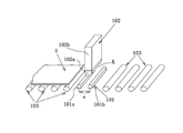
- FIG. 9 is a view showing an example of an embodiment in the case of performing such bending press molding.
- Reference numeral 101 in the figure denotes a die disposed in the conveyance path of the plate material S.
- the die 101 is composed of a pair of left and right rod-like members 101a and 101b that support the plate material S at two locations along the conveying direction, and the mutual distance e can be changed according to the size of the steel pipe to be formed. It has become. However, the mutual interval e is not changed in the process of manufacturing a single open tube by press-molding one sheet material S.
- Numeral 102 denotes a punch that can be moved in the direction of approaching or separating from the die 101.
- the punch 102 is connected to a punch tip portion 102a having a downward convex processing surface K that is in direct contact with the plate material S and presses the plate material S into a concave shape, and a back surface of the punch tip portion 102a.
- It consists of a punch support 102b that supports Usually, the maximum width of the punch tip 102a is equal to the width (thickness) of the punch support 102b.
- Reference numeral 103 denotes a roller that forms a conveyance path for the plate material S.
- Patent Document 1 discloses that the width of the steel plate is determined in press forming in the width direction of the steel plate.
- the straight part of the desired length remains at both end parts in the direction and the specific part in the middle, and the straight part is bent as an arc part, and the seam part is welded to form a semi-formed round steel pipe
- a method has been proposed in which the entire shape of the semi-formed round steel pipe is heated, and then the shape is adjusted by hot forming through a plurality of forming rolls having a semi-circular shape corresponding to the final radius.
- the molded body after press molding has a shape close to a quadrangle, and it is indispensable to separately provide a process (hot) for correcting the shape. If the consumption of heat energy for heating is included, there is a problem that the manufacturing cost is significantly increased.
- this method may impair the properties when a plate material manufactured through a thermomechanical process is used as an original plate in order to combine strength, toughness, and weldability.
- Patent Document 2 discloses a three-point bending press while relaxing stress acting on a connecting portion between a punch that functions as an upper tool and a bending board (corresponding to the punch support body) that supports the punch. A method for reducing the number of processing has been proposed.
- an object of the present invention is to efficiently perform bending without causing wear or deformation of a processing tool or deteriorating product quality when manufacturing a steel pipe from a plate material by a three-point bending press.
- the company is proposing a mold for bending press molding.
- the present invention is arranged at intervals along the feeding direction of the plate material, is a die that supports the plate material at two locations, is movable in the direction of approaching and separating from the die, and is supported by the die.
- a bending press molding die including a punch for bending the plate material by sequentially pressing the plate material in the feeding direction, and the punch directly contacts the plate material and presses the plate material
- a punch tip and a punch support that is connected and held to the back of the punch tip and supports the punch tip.
- the punch tip has a processing center that matches the axis of the punch support.
- a bending press molding die having a machining surface formed by a non-uniform arc having a maximum radius in the central region in the width direction.
- the non-uniform arc is a continuous arc or a discontinuous arc
- the non-uniform arc consists of an involute curve
- the continuous arc or the discontinuous arc has a radius corresponding to the inner diameter of the cylindrical body to be machined, and borders the machining center.
- a main arc having the same processing length (contact length) on the left and right sides, and a sub-arc having a radius smaller than the main arc connected to the width edge of the main arc.
- the arc that mainly contributes to the bending process has a machining length less than 0.90 times the feed amount of the plate material.
- the main arc is the feed amount of the plate material. Having a machining length of less than 0.90 times; Is preferable as a specific means for solving the problems of the present invention.
- the punch tip has a processing center that matches the axial center of the punch support, and the radius at the center in the width direction is the maximum radius. Since the machined surface made of a non-uniform arc is provided, even if the bending range of the plate material is increased, the width end of the machined surface does not come into strong contact with the plate material, causing punch deformation or damage. Generation of such an excessive bending moment can be suppressed, and a wider plate material can be processed at a time than before, so that a steel pipe having a high roundness can be obtained with a small number of processing operations. In addition, a process for heating the plate material is not necessary, and the characteristics such as strength, toughness and weldability obtained in the plate material (original plate) manufacturing process can be maintained as they are.
- the non-uniform arc is a continuous arc or a discontinuous arc combining at least two arcs having different radii.
- the width end does not come into strong contact with the plate material. For this reason, it is possible to avoid an excessive bending moment that causes deformation and damage of the punch. Further, the processed surface can be formed relatively easily.
- the punched surface can be easily formed by forming the non-uniform arc with an involute curve.
- continuous arcs and discontinuous arcs have radii corresponding to the inner diameters of the steel pipes to be machined, and the left and right machining lengths are equivalent to the machining center.
- a sub-arc having a radius smaller than the radius of the main arc and connected to the width end edge of the main arc. It is possible to reduce the unbalance of the force acting on the punch by reducing the difference in the distance from the contact start point to the punch center and the punch tip and support the punch while ensuring a wide punch processing width. It can be avoided that an extreme load is applied to the connecting portion with the body.
- the processing length of the region in which the arc that mainly contributes to bending is formed on the processing surface on which the non-uniform arc is formed is By setting the feed amount to less than 0.90 times, an excessive bending moment is not generated in the punch, so that the life of the punch can be extended and stable bending can be performed over a long period of time.
- the roundness of can be increased.
- the non-uniform arc is a continuous arc or a discontinuous arc
- the continuous arc or the discontinuous arc is constituted by a main arc and a sub-arc
- the main arc mainly contributes to bending. Therefore, an excessive bending moment can be prevented from occurring by setting the processing length of the region where the main arc is formed to less than 0.90 times the feed amount of the plate.
- FIG. 1 is a view showing an embodiment of a bending press molding die according to the present invention.
- FIG. 2 is a diagram schematically showing a deformed state of the plate material when pressed using the bending press molding die shown in FIG. 3 (a) to 3 (c) are diagrams showing another embodiment of a bending press molding die.
- FIG. 4 is a diagram showing a bending process by bending press molding.
- FIG. 5 is a diagram schematically showing a deformation state of the plate material when bending press molding is performed using a punch having a uniform arc.
- FIG. 6 is an explanatory diagram of the processing length n i that contributes to the bending of the mold.
- FIG. 7 is a diagram showing specific dimensions of the punch used in the example.
- (A) is the figure which showed the dial gauge used when evaluating the local roundness of a steel pipe
- (b) is the figure which showed the measuring point of local roundness. It is the figure which showed an example of embodiment in the case of performing bending press molding according to the conventional method.
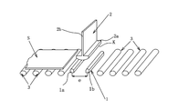
- FIG. 1 is a view showing an embodiment of a bending press molding die according to the present invention.
- Numeral 1 in the drawing is a die arranged in the conveying path of the plate material S.
- the die 1 is composed of a pair of left and right rod-like members 1a and 1b that support the plate material S at two locations along the feeding direction, and the mutual distance e can be changed according to the size of the steel pipe to be formed. It is like that. However, the mutual interval e is not changed in the process of manufacturing a single open tube by press-molding one sheet material S.
- Numeral 2 is a punch that is movable in the direction of approaching and separating from the die 1.
- the punch 2 is connected to the punch tip portion 2a having a downwardly convex machining surface K that directly contacts the plate material S and presses the plate material in a concave shape, and the back surface of the punch tip portion 2a, and supports the punch tip portion 2a.
- the punch support 2b is provided.
- Reference numeral 3 denotes a roller that forms a conveying path for the plate material S.
- the specific structure of the punch support 2b of the punch 2 is not shown, its upper end is connected to driving means such as a hydraulic cylinder, and the driving means applies a pressing force to the punch tip 2a. It can be granted.
- the width (thickness) of the punch support 2b is appropriately designed according to the plate thickness / strength of the plate material S, which is a material to be formed, and the shape of the tube to be formed. Moreover, since the punch support body 2b may contact the edge part of the board
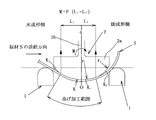
- the punch tip 2a of the punch 2 has a machining center O that matches the axis q of the punch support 2b, and is provided at the tip.
- a non-uniform arc having a radius r 1 in the center region in the width direction as a maximum radius (other portions have a radius r 2 smaller than the radius r 1 ) is formed.
- the non-uniform arc defined in the present invention is a combination of at least two arcs having different radii as shown in FIGS. 3A to 3C, that is, the machining center O. And an arc having a radius r 1 (hereinafter referred to as a main arc K 1 ) and an arc having a radius r 2 smaller than the main arc K 1 (hereinafter referred to as a sub-arc K 2 ). It shall be said to be done.
- the tangent and the angle of the tangent of the auxiliary arc K 2 be one is a 0 ° lead via a step d, the following an arc form as shown (a), the as continuous arcs (such involute curve
- an arc having a shape as shown in (b) and (c) is hereinafter referred to as a discontinuous arc.
- the discontinuous arc includes those in which the radius of the arc gradually changes.
- the punch 2 basically includes a punch tip 2a and a punch support 2b, but is not shown between the punch tip 2a and the punch support 2b.
- a spacer can be interposed.
- the attachment angle of the punch tip 2a to the punch support 2b is finely adjusted, the attachment angle can be adjusted only by adjusting the shape of the spacer instead of the punch support 2b itself. Can be adjusted to an appropriate angle.
- the punch tip 2a is divided in the longitudinal direction of the die 1, the punch tip 2a is stored by holding a plurality of divided punch tips 2a with a single spacer.
- the handling efficiency when the punch tip 2a is mounted on the punch support 2b can be improved. Because of the advantages as described above, it is preferable to interpose a spacer (not shown) between the punch tip 2a and the punch support 2b.
- the plate material S is placed on the die 1 and the plate material S is intermittently fed at a predetermined feed amount.
- the plate material S may be sequentially subjected to three-point bending with the punch 2 from the edge in the width direction toward the center on both the left and right sides. Note that FIG.
- FIG. 4 shows the plate material S that has been subjected to end bending (described later) from the top to the bottom of the left row, then from the top to the bottom of the center row, and from the top to the bottom of the right row 4 is a diagram showing a process of forming an open pipe as shown in the rightmost bottom view by performing bending and feeding of the plate material S, and an arrow attached to the plate material S or the punch 2 in FIG. Indicates the moving direction of the plate material S or the punch 2 in each step.
- the plate material S When the bending of the plate material S is advanced in such a state, the plate material S is more than the center in the width direction of the punch 2 (processing center O) in order to maintain the contact state between the punch 2 and the die 1. As shown in FIG. 5, the contact range (bending range) where the punch 2 comes into contact with the plate material S is not formed as compared with the pre-formed side. Widen on the side.
- the processed surface K has become a non-uniform arcuate, moreover, since the sub-arc K 2 smaller radius than the radius of the main arcuate K 1
- the asymmetric range can be made narrower than that of a punch having a single processing surface, and therefore the load in the width end region of the punch 2 becomes extremely large even if the processing of the plate S is progressing. As a result, it is possible to suppress the occurrence of an excessive bending moment.
- the main arc K 1 formed on the processed surface K is assumed to have the machining center ⁇ contact the left and right equivalent to the starting point length .
- the main arc K 1 and the auxiliary arc K 2 are, although continuing arcs was that constituted by discontinuous circular arc, the number of arcs is not limited particularly.
- the length (peripheral length) of the processed surface K is determined by the size of the steel pipe to be processed and the number of times of pressing, but the processed length of the region of the processed surface K formed mainly by an arc that contributes to bending. Is less than 0.90 times the feed amount (feed length) of the plate material (mainly contributing to the bending process) in order to reduce the bending moment generated in the punch 2 and reduce the number of pressings to realize an efficient bending process.
- the processing length of an arc is formed regions and n i, when the feed amount of the sheet material S was [delta], the ratio of the feed amount [delta] of the working length n i and sheet S (n i / [delta]) is (Less than 0.90 times).
- a working surface K main arc K 1 In the composed punch 2 from the sub-arc K 2, since that would main arc K 1 contributes primarily bending, formed in the main arc K 1 region
- the processing length is set to less than 0.90 times the plate feed amount
- the primarily bent length n i contributing to the machining arc is formed regions, as shown in FIG. 6, the bending the target around the processing center O in processing surface K of the punch 2 molding
- the amount (bending angle per rotation) ⁇ i means the length (arc length) on the processing surface K corresponding to the target range of the bending amount ⁇ i.
- the target bending forming amount ⁇ i is that when the number of times of processing is N, the plate material to be processed is bent into a 360 ° pipe shape together with end bending (360 ° ⁇ 2 ⁇ end bending).
- Angle) / N is a measure of the amount of bending performed per time.
- the number of times of processing N is usually 3 times or more, so the standard of the bending amount per time is a value calculated when the end bending angle is assumed to be 0 °. 120 ° is sufficient. Therefore, the amount of bending on the processed surface K of the punch 2 can be 120 ° or less (corresponding to 60 ° or less on one side with respect to the processing center O of the punch 2), and smaller 90 ° or less (processing of the punch 2). It may be equivalent to 45 ° or less on one side with respect to the center O).
- an end bending process (also referred to as crimping process) is applied to the plate width end of the plate material prior to bending press molding. This is performed in order to ensure high roundness at the plate width end portion, which is relatively difficult to bend as compared with the case where bending processing is performed on the center portion of the plate width by bending press molding. Then, since it is formed into a pipe shape by bending 360 ° together with the subsequent bending press forming, bending forming is applied except for the portion applied by end bending in bending press forming.
- the bending forming amount (angle) ⁇ i per time in the bending press is (360 ° ⁇ 2 ⁇ end bending angle) / N, and the range in which bending per time is given is the feed amount (feed length). Is).
- the plate material is formed into a pipe shape by applying a bending of the bending forming amount ⁇ i for each feeding amount.
- the shape in the range of the bending forming amount (center angle) ⁇ i is transferred onto the punch 2 to be the shape after the bending press.
- the length (peripheral length (or arc length)) along the processing surface K of the section of the bending forming amount ⁇ i is made closer to the feed amount of the plate material, the portion to which the curvature is given becomes wider, and the high roundness Can be secured.
- the position where the forming reaction force (processing reaction force) is received becomes farther from the processing center O of the processing surface K of the punch 2, and the bending at the connecting portion between the punch support 2b and the punch tip 2a is performed.
- the curvature radius of the bent portion of the plate material S is also reduced.
- a bent part having a smaller radius of curvature than that of the other part is formed locally on the tubular body that is the object to be molded, its shape is inferior when it remains in the product as it is.
- Secondary arcs K 2 of radius of the processing surface K because the main arc K 1 smaller than the radius, it is necessary to pay attention to the occurrence of such a problem. Therefore, bending range of the sub arc K 2 is preferably set to 15 ° or less at the center angle of the sub arc K 2,
- the thickness is preferably set working length of the area where the mainly curved arc contributes to machining is formed in accordance with the dimensions) (distance) n i appropriately.
- the feed pitch is 298 mm / time
- the bending forming amount is 29.6 ° / time
- the number of presses is 5 times.
- three-point bending was performed from both the left and right sides toward the center of the steel plate.
- a die having a radius of 75 mm at the tip and a mutual distance e (distance between the centers) of the rod-shaped members 1a and 1b was set to 550 mm.
- a punch tip having a width of 400 mm is used, and as a punch support for supporting the punch, as shown in FIG. 7, the width (thickness) of the main body is 100 mm, and the punch tip is attached to the tip.
- a strain gage is attached to the end of R having a radius of 50 mm (starting portion of R) provided at a connecting portion between the main body portion and the receiving portion using a fixing and holding portion having a width of 400 mm.
- the shape of the machined surface is a continuous arc.
- the main arc and the sub-arc are located at an angle of 15 ° from the machining center O of the punch tip, and the tangent of the main arc and the tangent of the sub-arc.
- the form of the processed surface is involute is a case where bending is performed using a punch having a processed surface whose radius gradually decreases as the distance from the processing center O of the punch tip portion increases due to the involute curve.
- the radius of the main arc is the value of the radius at the processing center O (that is, the maximum value of the radius), and the radius of the sub-arc is the bending amount ⁇ i : 29.6 from the processing center O.
- a position at a distance of 1 ⁇ 2 °, that is, a minimum value of a radius of a range that mainly contributes to bending is shown.
- the angle formed between the tangent line of the main arc and the tangent line of the sub arc is such that the main arc and the sub arc are 15 ° from the machining center O of the punch tip 2a. This is a case where bending is performed using a punch having a processing surface connected with a difference of 6 °.
- the stress acting on the punch support indicates the largest value among eleven bending operations.
- the stress acting on the punch support is represented by the number of 2 ⁇ 10 6 stress repetitions in the “Japanese Steel Structure Fatigue Design Guideline” for the punch support.
- the value divided by the basic allowable stress range that is, the ratio of the stress acting on the punch support to the basic allowable stress range is shown.
- the evaluation of the punch is that the stress acting on the punch support is less than the fatigue limit stress, that is, the ratio of the stress acting on the punch support to the fatigue limit stress is less than 1 (excellent), Those having a ratio of 1.25 or less are indicated by ⁇ (possible) and those having a ratio of 1.25 or less are indicated by ⁇ (impossible).
- the stress ratio 1.25 at which the number of stress repetitions is 1 ⁇ 10 6 times or more was set as the threshold value.
- the local roundness refers to, for example, a dial gauge 4 having a pair of legs 4a and 4b having a distance D between legs as shown in FIG. 8A, and the legs of the legs 4a and 4b.
- the ends 4c and 4d are brought into contact with the peripheral surface of the obtained steel pipe, and a probe (not shown) provided at the tip of the spindle 4e is further brought into contact with the peripheral surface of the steel pipe so that the virtual shape that is the target shape of the steel pipe is obtained. It is measured by reading the radial displacement from the perfect circle, and the smaller the value, the closer to the perfect circle.
- the local roundness as shown in FIG. 8B is measured along the circumferential direction of the peripheral surface of the steel pipe, and the measured local roundness is measured.
- the value of API-2 API of API-2B which is a typical standard for steel pipes, is less than 2.0mm, and the value of API-5L is less than 3.2mm. (Good), those exceeding the value are shown in Table 1 as x (impossible).
- punch No. suitable for the present invention In A to H, the ratio of stress applied to the punch support during bending was 1.25 or less, and no deformation or damage of the punch was observed. In addition, Punch N Th. It was confirmed that the steel pipe formed by the punches A to H had a local roundness of 2.3 mm or less and sufficiently satisfied the API standard.
- the local roundness of the steel pipe is 2.0 mm or less, and the API standard Among them, the strict 2B standard was satisfied, and it became clear that a steel pipe with good quality could be formed without adding an extra step.
- the punch No. with the smallest radius of the secondary arc is used.
- the stress ratio at the joint was the smallest, 0.87, and it was found that such a punch support can be used semipermanently.
- a bending press molding die capable of stably and efficiently forming a steel pipe having a high roundness over a long period of time is suppressed from affecting the deformation and damage of the punch due to the occurrence of an excessive bending moment. Can be provided.
Landscapes
- Engineering & Computer Science (AREA)
- Mechanical Engineering (AREA)
- Bending Of Plates, Rods, And Pipes (AREA)
Abstract
Description
1)非一様円弧が、連続円弧または不連続円弧からなること、
2)非一様円弧が、インボリュート曲線からなること、
3)非一様円弧が、連続円弧または不連続円弧から構成される場合において、該連続円弧、不連続円弧を、加工すべき円筒体の内径に対応する半径を有し、前記加工中心を境にして左右同等の加工長さ(接触長さ)を有する主円弧と、この主円弧の幅端縁につながり、該半径よりも小さい半径を有する副円弧にて構成すること、さらに
4)非一様円弧のうち、主として曲げ加工に寄与する円弧は、板材の送り量の0.90倍未満の加工長さを有すること
5)連続円弧、不連続円弧において、主円弧は、板材の送り量の0.90倍未満の加工長さを有すること、
が本発明の課題解決のための具体的手段として好ましい。
図1は、本発明に従うベンディングプレス成形用金型の実施の形態を示した図である。

た。また、パンチNо.A~Hのパンチによって成形された鋼管は局所真円度が2.3mm以下であり、API規格を充分に満足することが確認された。
1a、101a 棒状部材
1b、101b 棒状部材
2、102 パンチ
2a、102a パンチ先端部
2b、102b パンチ支持体
3、103 ローラ
4 ダイヤルゲージ
4a 脚部
4b 脚部
4c 脚端
4d 脚端
4e スピンドル
S 板材
e 相互間隔
K1 主円弧
K2 副円弧
r1 半径
r2 半径
О 加工中心
q 押圧軸芯
Claims (6)
- 板材の送給方向に沿い間隔をおいて配置され、該板材を二箇所において支持するダイと、このダイに近接、離隔する向きに移動可能で、かつ、前記ダイに支持された前記板材をその送給方向に沿って逐次押圧して曲げ加工を施すパンチとを備えたベンディングプレス成形用金型であって、
前記パンチは、前記板材に直に当接して前記板材を押圧するパンチ先端部と、該パンチ先端部の背面に連結され、該パンチ先端部を支持するパンチ支持体とを備え、
前記パンチ先端部に、前記パンチ支持体の軸芯に合致する加工中心を有し、その幅方向の中央域における半径を最大半径とする非一様円弧にて形成された加工面を設けたことを特徴とするベンディングプレス成形用金型。 - 前記非一様円弧が、異なる半径を有する少なくとも2つの円弧を組み合わせた連続円弧または不連続円弧であることを特徴とする請求項1に記載したベンディングプレス成形用金型。
- 前記非一様円弧が、インボリュート曲線からなることを特徴とする請求項1に記載したベンディングプレス成形用金型。
- 前記連続円弧または不連続円弧が、加工すべき鋼管の内径に対応する半径を有し、前記加工中心を境にして左右同等の加工長さを有する主円弧と、この主円弧の幅端縁につながり、該半径よりも小さい半径を有する副円弧からなることを特徴とする請求項2に記載したベンディングプレス成形用金型。
- 前記非一様円弧の、主として曲げ加工に寄与する円弧が形成された領域は、前記板材の送り量の0.90倍未満の加工長さを有することを特徴とする請求項1~3のいずれか1に記載したベンディングプレス成形用金型。
- 前記連続円弧または不連続円弧の、主円弧が形成された領域は、前記板材の送り量の0.90倍未満の加工長さを有することを特徴とする請求項4に記載したベンディングプレス成形用金型。
Priority Applications (6)
| Application Number | Priority Date | Filing Date | Title |
|---|---|---|---|
| KR1020167025853A KR101945091B1 (ko) | 2014-03-31 | 2015-03-30 | 벤딩 프레스 성형용 금형 |
| EP15772740.5A EP3127624B1 (en) | 2014-03-31 | 2015-03-30 | Bending-press forming tool |
| RU2016138627A RU2650468C2 (ru) | 2014-03-31 | 2015-03-30 | Пуансон для гибочного прессования |
| BR112016022887-1A BR112016022887B1 (pt) | 2014-03-31 | 2015-03-30 | prensa de flexão formadora de punção |
| CN201580016678.1A CN106132577B (zh) | 2014-03-31 | 2015-03-30 | 弯曲冲压成形用模具 |
| SA516371950A SA516371950B1 (ar) | 2014-03-31 | 2016-09-29 | برامة تشكيل بمكبس ثني |
Applications Claiming Priority (4)
| Application Number | Priority Date | Filing Date | Title |
|---|---|---|---|
| JP2014-072523 | 2014-03-31 | ||
| JP2014072523 | 2014-03-31 | ||
| JP2015046163A JP6262166B2 (ja) | 2014-03-31 | 2015-03-09 | ベンディングプレス成形用金型 |
| JP2015-046163 | 2015-03-09 |
Publications (1)
| Publication Number | Publication Date |
|---|---|
| WO2015152107A1 true WO2015152107A1 (ja) | 2015-10-08 |
Family
ID=54240430
Family Applications (1)
| Application Number | Title | Priority Date | Filing Date |
|---|---|---|---|
| PCT/JP2015/059833 Ceased WO2015152107A1 (ja) | 2014-03-31 | 2015-03-30 | ベンディングプレス成形用金型 |
Country Status (8)
| Country | Link |
|---|---|
| EP (1) | EP3127624B1 (ja) |
| JP (1) | JP6262166B2 (ja) |
| KR (1) | KR101945091B1 (ja) |
| CN (1) | CN106132577B (ja) |
| BR (1) | BR112016022887B1 (ja) |
| RU (1) | RU2650468C2 (ja) |
| SA (1) | SA516371950B1 (ja) |
| WO (1) | WO2015152107A1 (ja) |
Cited By (8)
| Publication number | Priority date | Publication date | Assignee | Title |
|---|---|---|---|---|
| CN107695163A (zh) * | 2017-10-10 | 2018-02-16 | 上海新闵(东台)重型锻造有限公司 | 核岛蒸发器封头整体冲压成型装置及冲压成型方法 |
| CN108435926A (zh) * | 2018-06-25 | 2018-08-24 | 湖北航嘉麦格纳座椅系统有限公司 | 一种冲床用的弯曲模 |
| CN110497490A (zh) * | 2018-05-17 | 2019-11-26 | 浙江三箭工贸有限公司 | 一种竹框部件冲压模具总成及冲压方法 |
| CN112091007A (zh) * | 2020-09-02 | 2020-12-18 | 中铁宝桥集团有限公司 | 一种隧道用大半径圆弧薄板曲面加工方法 |
| CN112518235A (zh) * | 2020-10-14 | 2021-03-19 | 江门市亿高电器有限公司 | 一种圆筒直缝工件的制造方法 |
| CN114659893A (zh) * | 2022-03-24 | 2022-06-24 | 山东钢铁集团日照有限公司 | 一种板材及管材压缩性能测试装置及方法 |
| CN115847692A (zh) * | 2022-12-11 | 2023-03-28 | 江苏二月二新材料有限公司 | 一种建筑圆柱模板压合机及其压合方法 |
| CN118952635A (zh) * | 2024-08-13 | 2024-11-15 | 重庆材料研究院有限公司 | 一种铠装加热电缆t形弯绕成型的加工装置 |
Families Citing this family (22)
| Publication number | Priority date | Publication date | Assignee | Title |
|---|---|---|---|---|
| JP6112740B2 (ja) * | 2014-03-31 | 2017-04-12 | Jfeスチール株式会社 | 3点曲げプレス成形による鋼管の成形方法および成形装置 |
| KR101642938B1 (ko) * | 2016-02-15 | 2016-07-26 | 라이텍엔지니어링(주) | 조이너 |
| CN107442730B (zh) * | 2017-10-10 | 2023-05-30 | 上海新闵(东台)重型锻造有限公司 | 核电蒸发器封头整体成型冲头 |
| CN107716627A (zh) * | 2017-10-26 | 2018-02-23 | 天津天重中直科技工程有限公司 | 一种大型压力折弯系统 |
| CN107952844A (zh) * | 2017-12-27 | 2018-04-24 | 佛山市达普光机电科技有限公司 | 一种小批量汽车防撞梁弯曲装置 |
| CN108160778A (zh) * | 2017-12-27 | 2018-06-15 | 佛山市达普光机电科技有限公司 | 一种气缸定位式小批量汽车防撞梁弯曲装置 |
| CN108580621A (zh) * | 2018-06-04 | 2018-09-28 | 北京京诚之星科技开发有限公司 | 一种波纹板模压起弧机 |
| CN108555089B (zh) * | 2018-06-11 | 2023-05-12 | 武汉船舶职业技术学院 | 三维曲面成型装置 |
| JP7137829B2 (ja) * | 2018-07-05 | 2022-09-15 | ナカジマ鋼管株式会社 | 丸形鋼管の製造方法、丸形鋼管製造設備 |
| DE102018211311B4 (de) * | 2018-07-09 | 2020-03-26 | Sms Group Gmbh | Erweiterte Regelung JCO-Formpresse |
| KR102425607B1 (ko) * | 2018-09-14 | 2022-07-27 | 제이에프이 스틸 가부시키가이샤 | 강관의 제조 방법 및 프레스 금형 |
| CN110961499B (zh) * | 2018-09-28 | 2021-06-15 | 宝山钢铁股份有限公司 | 一种u成形机模具的工作面型线及其生成方法 |
| KR20210091785A (ko) * | 2019-01-15 | 2021-07-22 | 데하르데 게엠베하 | 시트형 공작물의 형상을 변경시키기 위한 방법 및 설비 |
| CN112439812A (zh) * | 2019-08-31 | 2021-03-05 | 昆山嘉丰盛精密电子有限公司 | 弧形翘曲边成型方法 |
| JP7276758B2 (ja) * | 2020-03-16 | 2023-05-18 | 日軽金アクト株式会社 | 金型および金型を用いた加工方法 |
| CN114025896B (zh) * | 2020-05-15 | 2023-08-08 | 三菱制钢株式会社 | 中空弹簧及其制造方法 |
| CN113102599B (zh) * | 2021-04-26 | 2024-12-10 | 勋龙智造精密应用材料(苏州)股份有限公司 | 一种用于模具封水机构的冲击头 |
| KR102433479B1 (ko) * | 2021-09-01 | 2022-08-19 | 동의대학교 산학협력단 | 프레임부의 교체가 가능한 프레스 벤딩 장치 |
| CN114453521A (zh) * | 2022-02-11 | 2022-05-10 | 湖南翔龙飞机有限公司 | 飞机蒙皮现场冲压成型机 |
| JP7847030B2 (ja) * | 2022-04-28 | 2026-04-16 | 株式会社神戸製鋼所 | ヘミング加工品の製造方法 |
| CN115070424B (zh) * | 2022-07-08 | 2023-09-15 | 阜阳市节能化工工程有限公司 | 一种汽提塔冷凝器的配件加工组装设备 |
| CN119281893B (zh) * | 2024-11-21 | 2026-02-27 | 山东勤大轴承科技有限公司 | 一种轴承用钢管生产用冲压装置及使用方法 |
Citations (5)
| Publication number | Priority date | Publication date | Assignee | Title |
|---|---|---|---|---|
| DE19504736A1 (de) * | 1995-02-06 | 1996-08-14 | Mannesmann Ag | Verfahren und Vorrichtung zum Herstellen längsnahtgeschweißter Großrohre |
| JP2004082219A (ja) * | 2002-07-15 | 2004-03-18 | Sms Meer Gmbh | 金属板から管を製造するための装置 |
| JP2004261845A (ja) * | 2003-03-03 | 2004-09-24 | Jfe Steel Kk | Uプレス工具及びuoe鋼管の製造方法 |
| JP2005324255A (ja) * | 2005-06-17 | 2005-11-24 | Nakajima Steel Pipe Co Ltd | 丸鋼管の製造方法 |
| JP2012250285A (ja) * | 2011-05-31 | 2012-12-20 | Sms Meer Gmbh | 板材からスリット管を製造する方法及び装置 |
Family Cites Families (9)
| Publication number | Priority date | Publication date | Assignee | Title |
|---|---|---|---|---|
| JPS5118253A (ja) * | 1974-08-06 | 1976-02-13 | Osaka Tetsuen Kikai Kk | Kokanseikeiyopuresusochi |
| US4294095A (en) * | 1978-11-22 | 1981-10-13 | Nippon Steel Corporation | Process for fabricating heavy wall to pipe |
| JPS6043813B2 (ja) * | 1978-11-22 | 1985-09-30 | 新日本製鐵株式会社 | 厚肉uo鋼管成形法 |
| JPS5927649B2 (ja) * | 1979-10-03 | 1984-07-07 | 日本鋼管株式会社 | U、o、e方式による鋼管製造におけるuプレス方法 |
| JPS57187115A (en) * | 1981-05-13 | 1982-11-17 | Topy Ind Ltd | Roll-working method of cylinder |
| JPS59209425A (ja) * | 1983-05-12 | 1984-11-28 | Nippon Kokan Kk <Nkk> | Uoe鋼管製造プロセス用uプレス工具 |
| DE3632952A1 (de) * | 1986-09-27 | 1988-04-07 | Hoesch Ag | Verfahren und vorrichtung zur kontinuierlichen herstellung rohrfoermiger koerper mittels laser-laengsnahtschweissung |
| JP5082544B2 (ja) * | 2007-03-30 | 2012-11-28 | Jfeスチール株式会社 | 板の曲げ成形装置および曲げ成形方法 |
| DE102011009660B4 (de) * | 2011-01-27 | 2013-05-29 | Sms Meer Gmbh | Vorrichtung und Verfahren zum Umformen von Flachprodukten in Schlitzrohre oder Rohrvorprodukte |
-
2015
- 2015-03-09 JP JP2015046163A patent/JP6262166B2/ja active Active
- 2015-03-30 KR KR1020167025853A patent/KR101945091B1/ko active Active
- 2015-03-30 WO PCT/JP2015/059833 patent/WO2015152107A1/ja not_active Ceased
- 2015-03-30 CN CN201580016678.1A patent/CN106132577B/zh active Active
- 2015-03-30 BR BR112016022887-1A patent/BR112016022887B1/pt active IP Right Grant
- 2015-03-30 RU RU2016138627A patent/RU2650468C2/ru active
- 2015-03-30 EP EP15772740.5A patent/EP3127624B1/en active Active
-
2016
- 2016-09-29 SA SA516371950A patent/SA516371950B1/ar unknown
Patent Citations (5)
| Publication number | Priority date | Publication date | Assignee | Title |
|---|---|---|---|---|
| DE19504736A1 (de) * | 1995-02-06 | 1996-08-14 | Mannesmann Ag | Verfahren und Vorrichtung zum Herstellen längsnahtgeschweißter Großrohre |
| JP2004082219A (ja) * | 2002-07-15 | 2004-03-18 | Sms Meer Gmbh | 金属板から管を製造するための装置 |
| JP2004261845A (ja) * | 2003-03-03 | 2004-09-24 | Jfe Steel Kk | Uプレス工具及びuoe鋼管の製造方法 |
| JP2005324255A (ja) * | 2005-06-17 | 2005-11-24 | Nakajima Steel Pipe Co Ltd | 丸鋼管の製造方法 |
| JP2012250285A (ja) * | 2011-05-31 | 2012-12-20 | Sms Meer Gmbh | 板材からスリット管を製造する方法及び装置 |
Non-Patent Citations (1)
| Title |
|---|
| See also references of EP3127624A4 * |
Cited By (10)
| Publication number | Priority date | Publication date | Assignee | Title |
|---|---|---|---|---|
| CN107695163A (zh) * | 2017-10-10 | 2018-02-16 | 上海新闵(东台)重型锻造有限公司 | 核岛蒸发器封头整体冲压成型装置及冲压成型方法 |
| CN107695163B (zh) * | 2017-10-10 | 2023-06-16 | 上海新闵(东台)重型锻造有限公司 | 核岛蒸发器封头整体冲压成型装置及冲压成型方法 |
| CN110497490A (zh) * | 2018-05-17 | 2019-11-26 | 浙江三箭工贸有限公司 | 一种竹框部件冲压模具总成及冲压方法 |
| CN108435926A (zh) * | 2018-06-25 | 2018-08-24 | 湖北航嘉麦格纳座椅系统有限公司 | 一种冲床用的弯曲模 |
| CN112091007A (zh) * | 2020-09-02 | 2020-12-18 | 中铁宝桥集团有限公司 | 一种隧道用大半径圆弧薄板曲面加工方法 |
| CN112518235A (zh) * | 2020-10-14 | 2021-03-19 | 江门市亿高电器有限公司 | 一种圆筒直缝工件的制造方法 |
| CN114659893A (zh) * | 2022-03-24 | 2022-06-24 | 山东钢铁集团日照有限公司 | 一种板材及管材压缩性能测试装置及方法 |
| CN115847692A (zh) * | 2022-12-11 | 2023-03-28 | 江苏二月二新材料有限公司 | 一种建筑圆柱模板压合机及其压合方法 |
| CN115847692B (zh) * | 2022-12-11 | 2023-10-13 | 江苏二月二新材料有限公司 | 一种建筑圆柱模板压合机及其压合方法 |
| CN118952635A (zh) * | 2024-08-13 | 2024-11-15 | 重庆材料研究院有限公司 | 一种铠装加热电缆t形弯绕成型的加工装置 |
Also Published As
| Publication number | Publication date |
|---|---|
| CN106132577B (zh) | 2019-01-29 |
| EP3127624B1 (en) | 2022-11-30 |
| JP6262166B2 (ja) | 2018-01-17 |
| JP2015199126A (ja) | 2015-11-12 |
| BR112016022887B1 (pt) | 2021-01-12 |
| KR20160124848A (ko) | 2016-10-28 |
| EP3127624A4 (en) | 2017-04-26 |
| CN106132577A (zh) | 2016-11-16 |
| RU2016138627A (ru) | 2018-04-02 |
| SA516371950B1 (ar) | 2020-12-30 |
| KR101945091B1 (ko) | 2019-02-01 |
| RU2016138627A3 (ja) | 2018-04-02 |
| EP3127624A1 (en) | 2017-02-08 |
| RU2650468C2 (ru) | 2018-04-13 |
Similar Documents
| Publication | Publication Date | Title |
|---|---|---|
| JP6262166B2 (ja) | ベンディングプレス成形用金型 | |
| JP6721108B2 (ja) | プレス金型及び鋼管の製造方法 | |
| RU2456108C1 (ru) | Способ изготовления стальной трубы большого диаметра | |
| JP6070967B2 (ja) | 溶接鋼管の製造方法 | |
| JP2012170977A (ja) | 鋼管の製造方法 | |
| WO2016084607A1 (ja) | 鋼管の製造方法及びその方法に使用するプレス金型 | |
| EP2883627B1 (en) | Method of producing steel pipe | |
| JP2011045923A (ja) | 差厚金属板及びその製造方法 | |
| JP6566231B1 (ja) | 鋼板の端曲げ方法および装置並びに鋼管の製造方法および設備 | |
| JP6015686B2 (ja) | 電縫鋼管の製造方法 | |
| KR101744799B1 (ko) | 관재 액압성형장치 | |
| JP5135540B2 (ja) | 鋼管製造設備及び鋼管製造方法 | |
| JP2019177395A (ja) | 鋼板の端曲げ方法および装置並びに鋼管の製造方法および設備 | |
| KR102425607B1 (ko) | 강관의 제조 방법 및 프레스 금형 | |
| JP6566232B1 (ja) | 鋼板の端曲げ方法および装置並びに鋼管の製造方法および設備 | |
| KR101526342B1 (ko) | 소경 금속관의 제조 방법 및 제조 장치 | |
| JP4924653B2 (ja) | 円筒軸の製造方法 | |
| KR20080056278A (ko) | 우수한 용접부 특성을 갖는 용접관의 제조 장치 | |
| JP2015193013A (ja) | 鋼管の製造方法およびその製造装置 | |
| JP2015193024A (ja) | 板材のベンディングプレス成形方法及びそのベンディングプレス成形方法を用いた鋼管の製造方法 |
Legal Events
| Date | Code | Title | Description |
|---|---|---|---|
| 121 | Ep: the epo has been informed by wipo that ep was designated in this application |
Ref document number: 15772740 Country of ref document: EP Kind code of ref document: A1 |
|
| ENP | Entry into the national phase |
Ref document number: 20167025853 Country of ref document: KR Kind code of ref document: A |
|
| ENP | Entry into the national phase |
Ref document number: 2016138627 Country of ref document: RU Kind code of ref document: A |
|
| NENP | Non-entry into the national phase |
Ref country code: DE |
|
| REEP | Request for entry into the european phase |
Ref document number: 2015772740 Country of ref document: EP |
|
| WWE | Wipo information: entry into national phase |
Ref document number: 2015772740 Country of ref document: EP |
|
| REG | Reference to national code |
Ref country code: BR Ref legal event code: B01A Ref document number: 112016022887 Country of ref document: BR |
|
| ENP | Entry into the national phase |
Ref document number: 112016022887 Country of ref document: BR Kind code of ref document: A2 Effective date: 20160930 |