WO2015152247A1 - 防食用陽極、それを用いたコンクリート構造物の防食構造および防食方法 - Google Patents
防食用陽極、それを用いたコンクリート構造物の防食構造および防食方法 Download PDFInfo
- Publication number
- WO2015152247A1 WO2015152247A1 PCT/JP2015/060138 JP2015060138W WO2015152247A1 WO 2015152247 A1 WO2015152247 A1 WO 2015152247A1 JP 2015060138 W JP2015060138 W JP 2015060138W WO 2015152247 A1 WO2015152247 A1 WO 2015152247A1
- Authority
- WO
- WIPO (PCT)
- Prior art keywords
- layer
- anticorrosion
- conductive layer
- anode
- electrolyte
- Prior art date
- Legal status (The legal status is an assumption and is not a legal conclusion. Google has not performed a legal analysis and makes no representation as to the accuracy of the status listed.)
- Ceased
Links
Images


Classifications
-
- C—CHEMISTRY; METALLURGY
- C23—COATING METALLIC MATERIAL; COATING MATERIAL WITH METALLIC MATERIAL; CHEMICAL SURFACE TREATMENT; DIFFUSION TREATMENT OF METALLIC MATERIAL; COATING BY VACUUM EVAPORATION, BY SPUTTERING, BY ION IMPLANTATION OR BY CHEMICAL VAPOUR DEPOSITION, IN GENERAL; INHIBITING CORROSION OF METALLIC MATERIAL OR INCRUSTATION IN GENERAL
- C23F—NON-MECHANICAL REMOVAL OF METALLIC MATERIAL FROM SURFACE; INHIBITING CORROSION OF METALLIC MATERIAL OR INCRUSTATION IN GENERAL; MULTI-STEP PROCESSES FOR SURFACE TREATMENT OF METALLIC MATERIAL INVOLVING AT LEAST ONE PROCESS PROVIDED FOR IN CLASS C23 AND AT LEAST ONE PROCESS COVERED BY SUBCLASS C21D OR C22F OR CLASS C25
- C23F13/00—Inhibiting corrosion of metals by anodic or cathodic protection
- C23F13/02—Inhibiting corrosion of metals by anodic or cathodic protection cathodic; Selection of conditions, parameters or procedures for cathodic protection, e.g. of electrical conditions
-
- C—CHEMISTRY; METALLURGY
- C23—COATING METALLIC MATERIAL; COATING MATERIAL WITH METALLIC MATERIAL; CHEMICAL SURFACE TREATMENT; DIFFUSION TREATMENT OF METALLIC MATERIAL; COATING BY VACUUM EVAPORATION, BY SPUTTERING, BY ION IMPLANTATION OR BY CHEMICAL VAPOUR DEPOSITION, IN GENERAL; INHIBITING CORROSION OF METALLIC MATERIAL OR INCRUSTATION IN GENERAL
- C23F—NON-MECHANICAL REMOVAL OF METALLIC MATERIAL FROM SURFACE; INHIBITING CORROSION OF METALLIC MATERIAL OR INCRUSTATION IN GENERAL; MULTI-STEP PROCESSES FOR SURFACE TREATMENT OF METALLIC MATERIAL INVOLVING AT LEAST ONE PROCESS PROVIDED FOR IN CLASS C23 AND AT LEAST ONE PROCESS COVERED BY SUBCLASS C21D OR C22F OR CLASS C25
- C23F13/00—Inhibiting corrosion of metals by anodic or cathodic protection
- C23F13/02—Inhibiting corrosion of metals by anodic or cathodic protection cathodic; Selection of conditions, parameters or procedures for cathodic protection, e.g. of electrical conditions
- C23F13/06—Constructional parts, or assemblies of cathodic-protection apparatus
- C23F13/08—Electrodes specially adapted for inhibiting corrosion by cathodic protection; Manufacture thereof; Conducting electric current thereto
- C23F13/16—Electrodes characterised by the combination of the structure and the material
-
- B—PERFORMING OPERATIONS; TRANSPORTING
- B32—LAYERED PRODUCTS
- B32B—LAYERED PRODUCTS, i.e. PRODUCTS BUILT-UP OF STRATA OF FLAT OR NON-FLAT, e.g. CELLULAR OR HONEYCOMB, FORM
- B32B13/00—Layered products comprising a a layer of water-setting substance, e.g. concrete, plaster, asbestos cement, or like builders' material
- B32B13/04—Layered products comprising a a layer of water-setting substance, e.g. concrete, plaster, asbestos cement, or like builders' material comprising such water setting substance as the main or only constituent of a layer, which is next to another layer of the same or of a different material
-
- B—PERFORMING OPERATIONS; TRANSPORTING
- B32—LAYERED PRODUCTS
- B32B—LAYERED PRODUCTS, i.e. PRODUCTS BUILT-UP OF STRATA OF FLAT OR NON-FLAT, e.g. CELLULAR OR HONEYCOMB, FORM
- B32B13/00—Layered products comprising a a layer of water-setting substance, e.g. concrete, plaster, asbestos cement, or like builders' material
- B32B13/04—Layered products comprising a a layer of water-setting substance, e.g. concrete, plaster, asbestos cement, or like builders' material comprising such water setting substance as the main or only constituent of a layer, which is next to another layer of the same or of a different material
- B32B13/12—Layered products comprising a a layer of water-setting substance, e.g. concrete, plaster, asbestos cement, or like builders' material comprising such water setting substance as the main or only constituent of a layer, which is next to another layer of the same or of a different material of synthetic resin
-
- B—PERFORMING OPERATIONS; TRANSPORTING
- B32—LAYERED PRODUCTS
- B32B—LAYERED PRODUCTS, i.e. PRODUCTS BUILT-UP OF STRATA OF FLAT OR NON-FLAT, e.g. CELLULAR OR HONEYCOMB, FORM
- B32B27/00—Layered products comprising a layer of synthetic resin
- B32B27/06—Layered products comprising a layer of synthetic resin as the main or only constituent of a layer, which is next to another layer of the same or of a different material
-
- B—PERFORMING OPERATIONS; TRANSPORTING
- B32—LAYERED PRODUCTS
- B32B—LAYERED PRODUCTS, i.e. PRODUCTS BUILT-UP OF STRATA OF FLAT OR NON-FLAT, e.g. CELLULAR OR HONEYCOMB, FORM
- B32B27/00—Layered products comprising a layer of synthetic resin
- B32B27/12—Layered products comprising a layer of synthetic resin next to a fibrous or filamentary layer
-
- B—PERFORMING OPERATIONS; TRANSPORTING
- B32—LAYERED PRODUCTS
- B32B—LAYERED PRODUCTS, i.e. PRODUCTS BUILT-UP OF STRATA OF FLAT OR NON-FLAT, e.g. CELLULAR OR HONEYCOMB, FORM
- B32B3/00—Layered products comprising a layer with external or internal discontinuities or unevennesses, or a layer of non-planar shape; Layered products comprising a layer having particular features of form
- B32B3/26—Layered products comprising a layer with external or internal discontinuities or unevennesses, or a layer of non-planar shape; Layered products comprising a layer having particular features of form characterised by a particular shape of the outline of the cross-section of a continuous layer; characterised by a layer with cavities or internal voids ; characterised by an apertured layer
- B32B3/266—Layered products comprising a layer with external or internal discontinuities or unevennesses, or a layer of non-planar shape; Layered products comprising a layer having particular features of form characterised by a particular shape of the outline of the cross-section of a continuous layer; characterised by a layer with cavities or internal voids ; characterised by an apertured layer characterised by an apertured layer, the apertures going through the whole thickness of the layer, e.g. expanded metal, perforated layer, slit layer regular cells B32B3/12
-
- B—PERFORMING OPERATIONS; TRANSPORTING
- B32—LAYERED PRODUCTS
- B32B—LAYERED PRODUCTS, i.e. PRODUCTS BUILT-UP OF STRATA OF FLAT OR NON-FLAT, e.g. CELLULAR OR HONEYCOMB, FORM
- B32B5/00—Layered products characterised by the non- homogeneity or physical structure, i.e. comprising a fibrous, filamentary, particulate or foam layer; Layered products characterised by having a layer differing constitutionally or physically in different parts
- B32B5/02—Layered products characterised by the non- homogeneity or physical structure, i.e. comprising a fibrous, filamentary, particulate or foam layer; Layered products characterised by having a layer differing constitutionally or physically in different parts characterised by structural features of a fibrous or filamentary layer
-
- B—PERFORMING OPERATIONS; TRANSPORTING
- B32—LAYERED PRODUCTS
- B32B—LAYERED PRODUCTS, i.e. PRODUCTS BUILT-UP OF STRATA OF FLAT OR NON-FLAT, e.g. CELLULAR OR HONEYCOMB, FORM
- B32B5/00—Layered products characterised by the non- homogeneity or physical structure, i.e. comprising a fibrous, filamentary, particulate or foam layer; Layered products characterised by having a layer differing constitutionally or physically in different parts
- B32B5/02—Layered products characterised by the non- homogeneity or physical structure, i.e. comprising a fibrous, filamentary, particulate or foam layer; Layered products characterised by having a layer differing constitutionally or physically in different parts characterised by structural features of a fibrous or filamentary layer
- B32B5/022—Non-woven fabric
-
- B—PERFORMING OPERATIONS; TRANSPORTING
- B32—LAYERED PRODUCTS
- B32B—LAYERED PRODUCTS, i.e. PRODUCTS BUILT-UP OF STRATA OF FLAT OR NON-FLAT, e.g. CELLULAR OR HONEYCOMB, FORM
- B32B7/00—Layered products characterised by the relation between layers; Layered products characterised by the relative orientation of features between layers, or by the relative values of a measurable parameter between layers, i.e. products comprising layers having different physical, chemical or physicochemical properties; Layered products characterised by the interconnection of layers
- B32B7/04—Interconnection of layers
- B32B7/06—Interconnection of layers permitting easy separation
-
- B—PERFORMING OPERATIONS; TRANSPORTING
- B32—LAYERED PRODUCTS
- B32B—LAYERED PRODUCTS, i.e. PRODUCTS BUILT-UP OF STRATA OF FLAT OR NON-FLAT, e.g. CELLULAR OR HONEYCOMB, FORM
- B32B7/00—Layered products characterised by the relation between layers; Layered products characterised by the relative orientation of features between layers, or by the relative values of a measurable parameter between layers, i.e. products comprising layers having different physical, chemical or physicochemical properties; Layered products characterised by the interconnection of layers
- B32B7/04—Interconnection of layers
- B32B7/12—Interconnection of layers using interposed adhesives or interposed materials with bonding properties
-
- C—CHEMISTRY; METALLURGY
- C23—COATING METALLIC MATERIAL; COATING MATERIAL WITH METALLIC MATERIAL; CHEMICAL SURFACE TREATMENT; DIFFUSION TREATMENT OF METALLIC MATERIAL; COATING BY VACUUM EVAPORATION, BY SPUTTERING, BY ION IMPLANTATION OR BY CHEMICAL VAPOUR DEPOSITION, IN GENERAL; INHIBITING CORROSION OF METALLIC MATERIAL OR INCRUSTATION IN GENERAL
- C23F—NON-MECHANICAL REMOVAL OF METALLIC MATERIAL FROM SURFACE; INHIBITING CORROSION OF METALLIC MATERIAL OR INCRUSTATION IN GENERAL; MULTI-STEP PROCESSES FOR SURFACE TREATMENT OF METALLIC MATERIAL INVOLVING AT LEAST ONE PROCESS PROVIDED FOR IN CLASS C23 AND AT LEAST ONE PROCESS COVERED BY SUBCLASS C21D OR C22F OR CLASS C25
- C23F13/00—Inhibiting corrosion of metals by anodic or cathodic protection
- C23F13/02—Inhibiting corrosion of metals by anodic or cathodic protection cathodic; Selection of conditions, parameters or procedures for cathodic protection, e.g. of electrical conditions
- C23F13/06—Constructional parts, or assemblies of cathodic-protection apparatus
-
- C—CHEMISTRY; METALLURGY
- C23—COATING METALLIC MATERIAL; COATING MATERIAL WITH METALLIC MATERIAL; CHEMICAL SURFACE TREATMENT; DIFFUSION TREATMENT OF METALLIC MATERIAL; COATING BY VACUUM EVAPORATION, BY SPUTTERING, BY ION IMPLANTATION OR BY CHEMICAL VAPOUR DEPOSITION, IN GENERAL; INHIBITING CORROSION OF METALLIC MATERIAL OR INCRUSTATION IN GENERAL
- C23F—NON-MECHANICAL REMOVAL OF METALLIC MATERIAL FROM SURFACE; INHIBITING CORROSION OF METALLIC MATERIAL OR INCRUSTATION IN GENERAL; MULTI-STEP PROCESSES FOR SURFACE TREATMENT OF METALLIC MATERIAL INVOLVING AT LEAST ONE PROCESS PROVIDED FOR IN CLASS C23 AND AT LEAST ONE PROCESS COVERED BY SUBCLASS C21D OR C22F OR CLASS C25
- C23F13/00—Inhibiting corrosion of metals by anodic or cathodic protection
- C23F13/02—Inhibiting corrosion of metals by anodic or cathodic protection cathodic; Selection of conditions, parameters or procedures for cathodic protection, e.g. of electrical conditions
- C23F13/06—Constructional parts, or assemblies of cathodic-protection apparatus
- C23F13/08—Electrodes specially adapted for inhibiting corrosion by cathodic protection; Manufacture thereof; Conducting electric current thereto
-
- E—FIXED CONSTRUCTIONS
- E02—HYDRAULIC ENGINEERING; FOUNDATIONS; SOIL SHIFTING
- E02D—FOUNDATIONS; EXCAVATIONS; EMBANKMENTS; UNDERGROUND OR UNDERWATER STRUCTURES
- E02D31/00—Protective arrangements for foundations or foundation structures; Ground foundation measures for protecting the soil or the subsoil water, e.g. preventing or counteracting oil pollution
-
- E—FIXED CONSTRUCTIONS
- E04—BUILDING
- E04B—GENERAL BUILDING CONSTRUCTIONS; WALLS, e.g. PARTITIONS; ROOFS; FLOORS; CEILINGS; INSULATION OR OTHER PROTECTION OF BUILDINGS
- E04B1/00—Constructions in general; Structures which are not restricted either to walls, e.g. partitions, or floors or ceilings or roofs
- E04B1/62—Insulation or other protection; Elements or use of specified material therefor
-
- B—PERFORMING OPERATIONS; TRANSPORTING
- B32—LAYERED PRODUCTS
- B32B—LAYERED PRODUCTS, i.e. PRODUCTS BUILT-UP OF STRATA OF FLAT OR NON-FLAT, e.g. CELLULAR OR HONEYCOMB, FORM
- B32B2250/00—Layers arrangement
- B32B2250/44—Number of layers variable across the laminate
-
- B—PERFORMING OPERATIONS; TRANSPORTING
- B32—LAYERED PRODUCTS
- B32B—LAYERED PRODUCTS, i.e. PRODUCTS BUILT-UP OF STRATA OF FLAT OR NON-FLAT, e.g. CELLULAR OR HONEYCOMB, FORM
- B32B2255/00—Coating on the layer surface
- B32B2255/10—Coating on the layer surface on synthetic resin layer or on natural or synthetic rubber layer
-
- B—PERFORMING OPERATIONS; TRANSPORTING
- B32—LAYERED PRODUCTS
- B32B—LAYERED PRODUCTS, i.e. PRODUCTS BUILT-UP OF STRATA OF FLAT OR NON-FLAT, e.g. CELLULAR OR HONEYCOMB, FORM
- B32B2255/00—Coating on the layer surface
- B32B2255/26—Polymeric coating
-
- B—PERFORMING OPERATIONS; TRANSPORTING
- B32—LAYERED PRODUCTS
- B32B—LAYERED PRODUCTS, i.e. PRODUCTS BUILT-UP OF STRATA OF FLAT OR NON-FLAT, e.g. CELLULAR OR HONEYCOMB, FORM
- B32B2260/00—Layered product comprising an impregnated, embedded, or bonded layer wherein the layer comprises an impregnation, embedding, or binder material
- B32B2260/02—Composition of the impregnated, bonded or embedded layer
- B32B2260/021—Fibrous or filamentary layer
-
- B—PERFORMING OPERATIONS; TRANSPORTING
- B32—LAYERED PRODUCTS
- B32B—LAYERED PRODUCTS, i.e. PRODUCTS BUILT-UP OF STRATA OF FLAT OR NON-FLAT, e.g. CELLULAR OR HONEYCOMB, FORM
- B32B2260/00—Layered product comprising an impregnated, embedded, or bonded layer wherein the layer comprises an impregnation, embedding, or binder material
- B32B2260/04—Impregnation, embedding, or binder material
- B32B2260/046—Synthetic resin
-
- B—PERFORMING OPERATIONS; TRANSPORTING
- B32—LAYERED PRODUCTS
- B32B—LAYERED PRODUCTS, i.e. PRODUCTS BUILT-UP OF STRATA OF FLAT OR NON-FLAT, e.g. CELLULAR OR HONEYCOMB, FORM
- B32B2262/00—Composition or structural features of fibres which form a fibrous or filamentary layer or are present as additives
- B32B2262/02—Synthetic macromolecular fibres
- B32B2262/0253—Polyolefin fibres
-
- B—PERFORMING OPERATIONS; TRANSPORTING
- B32—LAYERED PRODUCTS
- B32B—LAYERED PRODUCTS, i.e. PRODUCTS BUILT-UP OF STRATA OF FLAT OR NON-FLAT, e.g. CELLULAR OR HONEYCOMB, FORM
- B32B2262/00—Composition or structural features of fibres which form a fibrous or filamentary layer or are present as additives
- B32B2262/10—Inorganic fibres
- B32B2262/106—Carbon fibres, e.g. graphite fibres
-
- B—PERFORMING OPERATIONS; TRANSPORTING
- B32—LAYERED PRODUCTS
- B32B—LAYERED PRODUCTS, i.e. PRODUCTS BUILT-UP OF STRATA OF FLAT OR NON-FLAT, e.g. CELLULAR OR HONEYCOMB, FORM
- B32B2307/00—Properties of the layers or laminate
- B32B2307/20—Properties of the layers or laminate having particular electrical or magnetic properties, e.g. piezoelectric
- B32B2307/202—Conductive
-
- B—PERFORMING OPERATIONS; TRANSPORTING
- B32—LAYERED PRODUCTS
- B32B—LAYERED PRODUCTS, i.e. PRODUCTS BUILT-UP OF STRATA OF FLAT OR NON-FLAT, e.g. CELLULAR OR HONEYCOMB, FORM
- B32B2307/00—Properties of the layers or laminate
- B32B2307/70—Other properties
- B32B2307/714—Inert, i.e. inert to chemical degradation, corrosion
-
- B—PERFORMING OPERATIONS; TRANSPORTING
- B32—LAYERED PRODUCTS
- B32B—LAYERED PRODUCTS, i.e. PRODUCTS BUILT-UP OF STRATA OF FLAT OR NON-FLAT, e.g. CELLULAR OR HONEYCOMB, FORM
- B32B2307/00—Properties of the layers or laminate
- B32B2307/70—Other properties
- B32B2307/724—Permeability to gases, adsorption
-
- B—PERFORMING OPERATIONS; TRANSPORTING
- B32—LAYERED PRODUCTS
- B32B—LAYERED PRODUCTS, i.e. PRODUCTS BUILT-UP OF STRATA OF FLAT OR NON-FLAT, e.g. CELLULAR OR HONEYCOMB, FORM
- B32B2307/00—Properties of the layers or laminate
- B32B2307/70—Other properties
- B32B2307/724—Permeability to gases, adsorption
- B32B2307/7242—Non-permeable
-
- B—PERFORMING OPERATIONS; TRANSPORTING
- B32—LAYERED PRODUCTS
- B32B—LAYERED PRODUCTS, i.e. PRODUCTS BUILT-UP OF STRATA OF FLAT OR NON-FLAT, e.g. CELLULAR OR HONEYCOMB, FORM
- B32B2307/00—Properties of the layers or laminate
- B32B2307/70—Other properties
- B32B2307/748—Releasability
-
- B—PERFORMING OPERATIONS; TRANSPORTING
- B32—LAYERED PRODUCTS
- B32B—LAYERED PRODUCTS, i.e. PRODUCTS BUILT-UP OF STRATA OF FLAT OR NON-FLAT, e.g. CELLULAR OR HONEYCOMB, FORM
- B32B2307/00—Properties of the layers or laminate
- B32B2307/70—Other properties
- B32B2307/752—Corrosion inhibitor
-
- B—PERFORMING OPERATIONS; TRANSPORTING
- B32—LAYERED PRODUCTS
- B32B—LAYERED PRODUCTS, i.e. PRODUCTS BUILT-UP OF STRATA OF FLAT OR NON-FLAT, e.g. CELLULAR OR HONEYCOMB, FORM
- B32B2457/00—Electrical equipment
- B32B2457/18—Fuel cells
-
- B—PERFORMING OPERATIONS; TRANSPORTING
- B32—LAYERED PRODUCTS
- B32B—LAYERED PRODUCTS, i.e. PRODUCTS BUILT-UP OF STRATA OF FLAT OR NON-FLAT, e.g. CELLULAR OR HONEYCOMB, FORM
- B32B2571/00—Protective equipment
-
- C—CHEMISTRY; METALLURGY
- C23—COATING METALLIC MATERIAL; COATING MATERIAL WITH METALLIC MATERIAL; CHEMICAL SURFACE TREATMENT; DIFFUSION TREATMENT OF METALLIC MATERIAL; COATING BY VACUUM EVAPORATION, BY SPUTTERING, BY ION IMPLANTATION OR BY CHEMICAL VAPOUR DEPOSITION, IN GENERAL; INHIBITING CORROSION OF METALLIC MATERIAL OR INCRUSTATION IN GENERAL
- C23F—NON-MECHANICAL REMOVAL OF METALLIC MATERIAL FROM SURFACE; INHIBITING CORROSION OF METALLIC MATERIAL OR INCRUSTATION IN GENERAL; MULTI-STEP PROCESSES FOR SURFACE TREATMENT OF METALLIC MATERIAL INVOLVING AT LEAST ONE PROCESS PROVIDED FOR IN CLASS C23 AND AT LEAST ONE PROCESS COVERED BY SUBCLASS C21D OR C22F OR CLASS C25
- C23F2201/00—Type of materials to be protected by cathodic protection
- C23F2201/02—Concrete, e.g. reinforced
-
- C—CHEMISTRY; METALLURGY
- C23—COATING METALLIC MATERIAL; COATING MATERIAL WITH METALLIC MATERIAL; CHEMICAL SURFACE TREATMENT; DIFFUSION TREATMENT OF METALLIC MATERIAL; COATING BY VACUUM EVAPORATION, BY SPUTTERING, BY ION IMPLANTATION OR BY CHEMICAL VAPOUR DEPOSITION, IN GENERAL; INHIBITING CORROSION OF METALLIC MATERIAL OR INCRUSTATION IN GENERAL
- C23F—NON-MECHANICAL REMOVAL OF METALLIC MATERIAL FROM SURFACE; INHIBITING CORROSION OF METALLIC MATERIAL OR INCRUSTATION IN GENERAL; MULTI-STEP PROCESSES FOR SURFACE TREATMENT OF METALLIC MATERIAL INVOLVING AT LEAST ONE PROCESS PROVIDED FOR IN CLASS C23 AND AT LEAST ONE PROCESS COVERED BY SUBCLASS C21D OR C22F OR CLASS C25
- C23F2213/00—Aspects of inhibiting corrosion of metals by anodic or cathodic protection
- C23F2213/20—Constructional parts or assemblies of the anodic or cathodic protection apparatus
- C23F2213/22—Constructional parts or assemblies of the anodic or cathodic protection apparatus characterized by the ionic conductor, e.g. humectant, hydratant or backfill
Definitions
- the present invention relates to an anticorrosion anode used for anticorrosion of reinforcing bars and the like covered with a concrete layer, an anticorrosion structure for a concrete structure using the same, and an anticorrosion method for the concrete structure.
- This application claims priority based on Japanese Patent Application No. 2014-071412 for which it applied to Japan on March 31, 2014, and uses the content here.
- an anticorrosion anode having high corrosion resistance such as titanium mesh, titanium grid, titanium rod or the like is installed directly on the surface of the concrete or provided with grooves or holes on the surface, and fixed with mortar. Therefore, there is a problem that an anode with high corrosion resistance is expensive and disadvantageous in terms of cost, and construction is troublesome.
- a method has been developed in which a titanium wire coated with platinum is attached to a concrete surface at an interval, and the entire concrete surface is coated with a conductive paint.
- this method has a problem that the potential distribution becomes non-uniform depending on the state of the contact surface between the conductive coating film and the concrete, and the conductive coating film is easily deteriorated due to an electrochemical reaction.
- Patent Document 1 uses a carbon fiber sheet coated with an oxidation-resistant metal having a passive film to reinforce a concrete structure and to suppress the destruction of the passive film.
- An anticorrosion method has been proposed in which a cement-based filler layer containing a passive state protective agent and an electrolyte is provided on the surface of a concrete structure to energize a carbon fiber sheet.
- a masking tape is affixed to the planned location of the filler layer on the concrete structure surface, and the adhesive is applied in a striped pattern. Thereafter, the masking tape is peeled off, and the carbon fiber sheet is adhered.
- the two pipes After pasting the carbon fiber sheet, the two pipes are passed through the place where the filler layer is to be installed, and air is exhausted through one pipe while the filler is passed through the other pipe through the carbon fiber sheet and the concrete structure. Inject between the surface. Thereafter, an impregnation adhesive is further impregnated from above the carbon fiber sheet. In this way, the work of providing the adhesive layer and the filler layer in a stripe shape requires overhead work in the anticorrosion work site where the back surface of a structure such as a bridge floor is often processed. So it becomes hard work.
- Patent Document 2 discloses an adhesive force that can be attached to one surface of a conductive layer formed of a carbon material in a sheet shape to the surface layer of the conductive layer and the body to be protected. There has been proposed an auxiliary anode in which an electrolyte layer formed into a sheet shape is attached.
- the anode is manufactured at the factory, and when the anode is installed in the field, the carbon material formed into a sheet shape is simply adhered to the concrete surface with an electrolyte layer. Very easy.
- the electrolyte layer is attached to the entire surface of the concrete at the portion to be prevented from being corroded, the charge transfer is performed more efficiently than in the case where the cement-based filler layer is provided in a stripe shape. Further, since the anode surface is not coated with the oxidation resistant metal, it is advantageous in terms of cost and the passive film is not destroyed.
- the anode can be easily installed and the charge transfer efficiency is good.
- the carbon material has a larger electric resistance than the metal, the energization state in the anode surface may not be uniform during energization. If the energization state in the anode surface is not uniform, it may be difficult to suppress the voltage to be energized and to carry out anticorrosion with less generation of gas due to electrolysis of water and chlorine compounds. Therefore, it is preferable to attach a power supply material along the longitudinal direction of the conductive layer to reduce the difference in energized state between the portion far from the drain point (positive electrode connecting portion of the external power source) and the portion close thereto.
- the labor for installing the power supply material is improved as compared with the method of Patent Document 1, there is a desire to omit the power supply material if possible because it takes time to manufacture the anode in the factory.
- This invention is made
- the present invention provides an anticorrosion anode that can suppress energization voltage, generate less gas due to electrolysis of water and chlorine compounds, and can prevent corrosion for a long time, and anticorrosion of a concrete structure using the same. Provide structure and anticorrosion method.
- the inventors of the present invention have a uniform state of energization to the concrete surface when performing anti-corrosion without using a power supply material, and efficiently convert to the movement of cations in the concrete.
- the present invention was completed by finding an electrolyte layer formed into a sheet shape having adhesive strength that can be attached to the surface of concrete, and a method that suitably uses a conductive layer made of a graphite sheet that is easily broken. .
- the present invention provides the following anticorrosion anode.
- a reinforcing layer made of a fiber base material is laminated on one surface of a conductive layer made of a graphite sheet using an adhesive layer, a resin containing an electrolyte is formed into a sheet shape, and the conductive layer
- an electrolyte layer having an adhesive force that can be attached to the surface layer of the object to be protected is an anode for corrosion prevention by an external power source attached to the other surface of the conductive layer by the adhesive force
- the conductive layer is an electrolyte layer
- This is an anticorrosion anode in which the resistance value between any two points on the surface in contact with the surface is always 4 ⁇ or less.
- the second aspect of the present invention is the anticorrosion anode according to the first aspect, in which the conductive layer has a large number of communication holes through which gas can permeate.
- the third aspect of the present invention is the anticorrosion anode according to the first aspect or the second aspect, in which the outer surface of the reinforcing layer is covered with an impermeable protective layer.
- a fourth aspect of the present invention is the anticorrosion anode according to any one of the first to third aspects, wherein the outer surface of the electrolyte layer is covered with a water-impermeable release paper.
- the present invention also provides the following anticorrosion structure for a concrete structure and anticorrosion method for a concrete structure.
- the anticorrosion anode according to any one of the first to fourth aspects is adhered to the surface of a concrete structure using an electrolyte layer, and the conductive layer of the anticorrosion anode is an external power source.
- the metal layer of the terminal having metal teeth bites into at least both the conductive layer and the reinforcing layer, so that the conductive layer is connected to the positive electrode of the external power source.
- the seventh aspect of the present invention is the anticorrosion by applying a voltage between the conductive layer of the anticorrosion anode and the subject to be protected using the anticorrosion structure of the concrete structure of the fifth aspect or the sixth aspect. This is a method for preventing corrosion of a concrete structure through which an electric current flows.
- the graphite sheet has a remarkably low volume resistivity in the horizontal direction (direction along the surface) as compared with the volume resistivity in the vertical direction (direction passing through the layer). Therefore, the resistance value between any two points of the conductive layer can always be 4 ⁇ or less. And even when the resistance value in the horizontal direction is low and the discharge point is provided at the corner, the conductive layer is formed into a sheet shape with a small difference in resistance value between the part close to the discharge point and the part far from the discharge point.
- the gel electrolyte is uniformly adhered over a wide area, the potential distribution of the surface layer of the corrosion-protected body when performing the anti-corrosion can be made uniform without using a power supply material. Since it is not necessary to install a power supply material, the anode can be easily manufactured, and the problem that the conductive layer in the vicinity of the power supply material may deteriorate when energized for a long time can be solved.
- a conductive layer made of a graphite sheet has high resistance (corrosion resistance) to gases such as oxygen and chlorine generated during energization and an electrolyte solution. Further, since graphite is used for the anode as a conductive layer, it is advantageous in terms of cost compared to the case where expensive corrosion-resistant metal such as titanium is used for the anode. Moreover, since a graphite sheet is light compared with a metal, an anode can be lightened. Then, the electrolyte layer can be attached to the conductive layer, and the anode can be attached to the surface layer of the corrosion-protected body using the surface of the electrolyte layer on which the conductive layer is not attached. Therefore, due to the fact that the anode is light, the amount of work at the site for installing the anticorrosion anode can be greatly reduced.
- the electrolyte layer can reduce the electrochemical polarization because the movement of electric charges from the external power source is efficiently converted into the ionic conduction of the electrolyte by the abundant ions of the electrolyte as compared with the concrete.
- the voltage applied to the anticorrosion anode can be set low, the generation of gas due to the electrolysis of water and chlorine compounds can be reduced. Therefore, the anticorrosion anode of the present invention can provide an anticorrosion effect even if the applied voltage is small, so that a solar cell, fuel cell, Corrosion protection is possible by using an independent power source such as a dry battery.
- the conductive layer has a large number of communication holes through which gas can permeate.
- the gas generated at the interface with the electrolyte layer can be released. Thereby, it can prevent that a conductive layer partially peels from an electrolyte layer. Therefore, as a first step, the corrosion current is applied to the reinforcing steel bar, and the corrosion is prevented by applying a voltage through which a large current flows. It is possible to perform corrosion prevention by applying a voltage with less generation of gas due to electrolysis.
- the corrosion prevention anode is reinforced without deteriorating the handling property and workability. Intrusion of physical damage, dirt, rain, flying salt, etc. of the layer, conductive layer, and electrolyte layer can be prevented.
- evaporation of the solvent in the electrolyte layer, physical damage, dirt, other articles Unintentional adhesion with can be prevented.
- the anticorrosion work can be easily performed and the amount of work at the construction site can be reduced.
- the corrosion prevention structure of the concrete structure can be obtained which is greatly reduced and does not have the possibility of peeling off the anticorrosion anode.
- the anticorrosion structure of the sixth aspect of the present invention in addition to the effect of the anticorrosion structure of the fifth aspect, a concrete structure that is easy to wire on the construction site and has no possibility of poor energization over a long period of time. An anticorrosion structure is obtained.
- the applied voltage can be kept low even when a large current is used for anticorrosion. Therefore, stable anticorrosion can be performed for a long time.
- FIG. 1 schematically shows an example of an anticorrosion anode 10 of the present invention and an example of an anticorrosion structure of a concrete structure using the same.
- reference numeral 1 is the anticorrosion structure of the present invention
- reference numeral 3 is a surface layer (concrete layer)
- reference numeral 4 is an anticorrosive body (reinforcing bar)
- reference numeral 5 is an external power supply
- reference numeral 6 is circuit wiring (conductor)
- Is an anode for corrosion protection of the present invention 11 is a conductive layer
- 12 is an electrolyte layer
- 13 is an adhesive layer
- 14 is a reinforcing layer
- 15 is a protective layer.
- the anticorrosion anode 10 is installed by sticking the electrolyte layer 12 to the surface of the concrete layer 3. Then, the circuit wiring 6 is used to connect the positive electrode of the external power supply 5 to the conductive layer 11 of the anticorrosion anode 10, and the circuit wiring 6 is used to connect the negative electrode of the external power supply 5 to the corrosion-protected body 4 to form an anticorrosion circuit.
- "sticking" means that objects are integrated by adhesion or adhesion. Adhesion means that objects can be peeled off at an intentional interface, but the objects are integrated with an adhesive strength that does not peel off in a natural state. Adhesion means that the objects are integrated with an adhesive strength that does not allow separation at the interface.
- a reinforcing layer 14 made of a fiber base material is laminated on one surface of a conductive layer 11 made of a graphite sheet using an adhesive layer 13.
- the electrolyte layer 12 is attached to the conductive layer 11 by its adhesive force.
- the electrolyte layer 12 has an adhesive force that can be attached to the conductive layer 11 and the surface layer 3 of the body 4 to be protected.
- the conductive layer 11 used in the present invention is a planar electrode that uniformly supplies the current supplied from the external power source 5 to the surface layer 3 of the corrosion-protected body 4 through the electrolyte layer 12.
- the conductive layer 11 always has a resistance value between any two points on the surface in contact with the electrolyte layer 12 (hereinafter, simply referred to as “resistance value between two points”) of 4 ⁇ or less.
- the conductive layer according to the method described in the example of Patent Document 2 supplies power along the longitudinal direction of the conductive layer in order to reduce the difference in the energization state between the portion far from the discharge point and the portion near the drain point. It is preferable to provide a material. If the stainless steel tape power supply material is actually provided along the longitudinal direction of the conductive layer using a conductive adhesive, the difference in the energized state between the portion far from the discharge point and the portion close thereto can be reduced.
- the stainless steel tape used at this time has a thickness of 30 ⁇ m, a width of 4 mm, and a length of 1000 mm. This stainless steel tape has an unexpectedly large actual resistance value of about 4 ⁇ . Therefore, in order to make the energization state by the conductive layer 11 uniform, the resistance value between the two points should always be 4 ⁇ or less in consideration of the contact resistance of the conductive adhesive.
- the volume resistivity in the vertical direction of the conductive layer 11 is not considered. Since it is good, it is preferable. In addition, since the conductive layer 11 has a thickness sufficiently smaller than the length of the side, the volume resistivity in the vertical direction can be ignored. Therefore, the anticorrosion anode 10 of the present invention is formed on the reinforcing layer 14 of the conductive layer 11. It is also possible to connect the contacting surface to the positive electrode of the external power supply 5.
- the thickness of the conductive layer 11 is not particularly limited as long as the resistance value between two points is 4 ⁇ or less. When the conductive layer 11 becomes thick, the resistance value between two points decreases, but this is disadvantageous in terms of cost. If the conductive layer 11 is thin, it is advantageous in terms of cost, but the resistance value between two points increases, and the mechanical strength may be insufficient. Therefore, the thickness of the conductive layer 11 is preferably about 0.01 mm to 2 mm.
- the graphite sheet used for the conductive layer 11 is preferably manufactured by the following method, for example.
- the graphite sheet by the expanding method is advantageous in terms of cost because the raw material is inexpensive and easy to manufacture, and the thickness control is relatively free and has flexibility.
- an oxidizing agent is used during the expansion treatment.
- the oxidizing agent is washed with water or the like, but it is difficult to remove it completely. Therefore, when used for a long period of time, the remaining oxidant gradually leaches out and may corrode the drain terminal connected to the conductive layer 11.
- a metal that does not easily oxidize or corrodes even if oxidized such as platinum, gold, silver, copper, titanium, and stainless steel.
- the graphite by an expanding method uses a binder at the time of compression molding, since the contact resistance between scaly graphite is high, it is difficult to obtain high electrical conductivity. However, the resistance value between two points required for the conductive layer 11 of the present invention can be easily achieved. Further, since the bonds between the scaly graphites are weak, the scaly graphites are easily separated. Accordingly, the graphite sheet alone may be damaged or torn depending on the handling method, and must be handled with care.
- a graphite sheet produced by a polymer film pyrolysis method in which a polymer film is directly carbonized and graphitized to produce a graphite sheet can also be used.
- a condensed aromatic polymer film that can be graphitized as a raw material it is preferable to use a condensed aromatic polymer film that can be graphitized as a raw material. Among them, an aromatic polyimide film is more preferable.
- the condensed aromatic polymer film is subjected to a preliminary heat treatment in an inert gas such as nitrogen or argon so that the maximum temperature is preferably 1000 ° C. to 1200 ° C.
- the temperature is raised at a specific rate in an inert gas, and a heat treatment is performed to set the maximum temperature to preferably 2500 ° C. or higher to produce a foamable sheet.
- rolling is performed using a roller or a press plate, and the film thickness, density, surface state, etc. of the sheet are made uniform.
- a graphite sheet having the same properties as single crystal graphite, high quality, high flexibility and toughness, and excellent thermal conductivity and electrical conductivity can be obtained.
- Graphite sheets obtained by polymer pyrolysis have the same electrical conductivity as single crystal graphite. Although it is expensive compared to graphite by the expanded method, it has high electrical conductivity, and there is no problem of flaking of graphite flakes, oxidizing agents, binders, etc., and it is strong against bending. In addition, graphite sheets obtained by polymer pyrolysis have extremely high thermal conductivity, and are therefore used for heat dissipation and soaking of CPUs and various electronic devices. Graphite sheets produced by polymer pyrolysis have excellent electrical conductivity and thermal conductivity, but the thickness is 1 mm or less due to the thickness of the raw material and the ease of the thermal decomposition reaction during the carbonization process. . Even if the graphite sheet by the polymer pyrolysis method is thin, the resistance value between two points can be lowered due to high conductivity.
- a graphite sheet produced by binding randomly dispersed carbon short fibers with resin carbide can also be used. Although this graphite sheet is expensive, it has a breathability in the vertical direction and is therefore used as a gas diffuser for fuel cells.
- a mixture of short carbon fibers having an average particle size of 1 to 30 ⁇ m and a papermaking medium containing an organic binder such as polyvinyl alcohol is made into a papermaking sheet by, for example, a round net paper machine.
- the paper sheet is heated and pressed to produce a sheet-like intermediate. Thereafter, the intermediate body is impregnated with a resin (for example, phenol resin, epoxy resin, furan resin, melamine resin, pitch, etc.) that is carbonized when heated to obtain a precursor fiber sheet.
- a resin for example, phenol resin, epoxy resin, furan resin, melamine resin, pitch, etc.
- the precursor fiber sheet is heated to at least 1,200 ° C. at a temperature increase rate in the range of 100 to 10,000 ° C./min in a heating furnace in an inert atmosphere, and the precursor fiber sheet is heated.
- a graphite sheet bound with a carbide of resin impregnated with short carbon fibers is obtained.
- carbon fiber constituting the short carbon fiber carbon fiber such as polyacrylonitrile (PAN), pitch, or rayon can be used.
- PAN-based or pitch-based carbon fibers it is preferable to use PAN-based or pitch-based carbon fibers because a porous carbon sheet having excellent mechanical strength, moderate flexibility, and excellent handleability can be obtained. .
- a graphite sheet manufactured by an expanding method or a polymer film pyrolysis method is used as the conductive layer 11 used in the anticorrosion anode 10 of the present invention, it may be difficult to transmit gas.
- a small voltage of 2 V or less is applied during anticorrosion, the amount of gas generated is extremely small, so even if the gas permeability is small, there is no practical problem.
- a graphite sheet obtained by an expanding method is used as the conductive layer 11 with priority given to cost advantages.
- the electrolyte layer 12 used in the anticorrosion anode 10 of the present invention converts the movement of electrons (electron conduction) due to the current supplied from the positive electrode of the external power source 5 to the conductive layer 11 into ionic conduction, and thereby the surface of the corrosion-resistant body 4. It is a layer that transfers charges to the layer 3.
- the electrolyte layer 12 is a charge transfer layer in which a resin containing ions having positive and negative charges is solidified into a sheet shape. Ions contained in the electrolyte layer 12 move, or charges move between these ions to move charges by ionic conduction.
- the electrolyte layer 12 has an adhesive force, and is adhered to the conductive layer 11 by the adhesive force.
- the electrolyte layer 12 is also an adhesive layer for adhering the anticorrosion anode 10 to the ion-permeable surface layer 3 existing on the surface of the object 4 to be protected, such as a concrete layer or a paint film, by its adhesive strength.
- the main electrolyte layer used for the electrolyte layer 12 includes a gel electrolyte layer in which an electrolyte solution is held in a resin matrix, a cation such as imidazolium ion and pyridinium ion, an anion such as BF 4 ⁇ and PF 6 ⁇ ,
- An ionic liquid layer (organic room temperature molten salt) composed of an ion gel layer in which a resin matrix is held, an intrinsic polymer electrolyte in which a polyether-based resin is held with a lithium salt such as bis (trifluoromethanesulfonyl) imide lithium (LiTFSI), etc.
- a polymer electrolyte layer can be mentioned.
- the gel electrolyte layer is preferable because it has high ionic conductivity and easily imparts flexibility and adhesiveness.
- the gel electrolyte layer is obtained by gelling (solidifying) an electrolyte in a resin matrix by adding a polymer, adding an oil gelling agent, polymerization containing polyfunctional monomers, a crosslinking reaction of the polymer, or the like.
- the electrolyte layer 12 is a gel electrolyte layer, when the anticorrosion anode 10 is adhered to the surface layer of the body 4 to be protected, for example, the concrete layer 3, a part of the electrolyte layer 12 is formed on the minute unevenness of the concrete layer 3. It is preferable because the electrolyte layer 12 can be brought into contact and stuck with high adhesive strength and a wide contact area.
- the thickness of the gel electrolyte layer used for the electrolyte layer 12 is not particularly limited, but is preferably 0.1 mm to 1 mm. Although there is no particular problem if the electrolyte layer 12 is thicker than this range, it is disadvantageous in terms of cost. If the electrolyte layer 12 is thinner than this range, the adhesive strength may be insufficient. In addition, when the electrolyte solution in the gel electrolyte layer is absorbed by the concrete layer 3, the charge transfer capability may decrease.
- the size of the electrolyte layer 12 is preferably the same size as the conductive layer 11 from the viewpoint of charge transfer.
- the electrolyte layer 12 is attached to the conductive layer 11 in a state where the entire surface of the electrolyte layer 12 is accurately overlaid on the entire surface of the conductive layer 11 because there is no useless surface from the viewpoint of charge transfer. . From the viewpoint of adhesion, it may be larger than the conductive layer 11, or from the viewpoint of workability when providing a discharge point, it may be smaller than the conductive layer 11.
- the gel electrolyte layer used for the electrolyte layer 12 has adhesiveness in which a solvent and an electrolyte salt, preferably a wetting agent are further held in a resin matrix obtained by copolymerizing a polymerizable monomer with a crosslinkable monomer. It is a conductive polymer gel electrolyte layer.
- the polymer gel electrolyte layer needs to be able to maintain a shape by holding a liquid solvent or the like in a three-dimensional network structure of polymer chains in which polymer chains are physically or chemically bonded. By appropriately designing the polymer three-dimensional network structure, a flexible polymer three-dimensional network structure skeleton (resin matrix) can be formed.
- Such a resin matrix has an appropriate cohesive force and good wettability to the surface of the adherend, so that the contact portion with the adherend can be approached at the molecular level. Moreover, since compressive strength and tensile strength are imparted to the gel by an appropriate cohesive force of the gel electrolyte layer, high adhesiveness can be obtained by mutual intermolecular force.
- the resin matrix of the gel electrolyte layer used for the electrolyte layer 12 may be subjected to a crosslinking treatment with a crosslinking agent in order to increase cohesion, or may be crosslinked by polymerizing a polymerizable monomer and a crosslinking monomer. It is preferable to keep it.
- a resin matrix in which polymer chains are three-dimensionally cross-linked is excellent in the ability to retain a solvent and a wetting agent. Thereby, it is possible to hold
- the polymerizable monomer forming the resin matrix is not particularly limited as long as it is a monomer having one polymerizable carbon-carbon double bond in the molecule.
- (Meth) acrylic acid derivatives (meth) acrylamide, N-methyl (meth) acrylamide, N-ethyl (meth) acrylamide, N-propyl (meth) acrylamide, N-butyl (meth) acrylamide, N, N-dimethyl ( (Meth) acrylamide, diacetone acrylamide, (meth) acrylamide derivatives such as N, N-dimethylaminopropyl (meth) acrylamide, t-butylacrylamide sulfonic acid, and salts thereof; N-vinylpyrrolidone, N-vinylformamide, N-vinylacetoa N- vinylamide derivatives such as de, vinyl sulfonic acid, and sulfonic acid monomers such as allyl sulfonic acid and salts thereof.
- (meth) acryl means acryl or methacryl.
- crosslinkable monomer that is polymerized and cross-linked with the polymerizable monomer
- a monomer having two or more double bonds having a polymerizable property in the molecule it is preferable to use a monomer having two or more double bonds having a polymerizable property in the molecule.
- polyfunctional (meth) acrylamide monomers such as methylene bis (meth) acrylamide, ethylene bis (meth) acrylamide, N, N-methylene bisacrylamide, N-methylol acrylamide; (poly) ethylene glycol di
- Polyfunctional (meth) acrylate monomers such as (meth) acrylate, (poly) propylene glycol di (meth) acrylate, glycerin di (meth) acrylate, glycerin tri (meth) acrylate, glycidyl (meth) acrylate; tetraallyloxy Ethane; diallylammonium chloride and the like.
- the content of the crosslinkable monomer is preferably 0.005 to 10 parts by weight with respect to 100 parts by weight of the resin matrix obtained by polymerizing and crosslinking the polymerizable monomer and the crosslinkable monomer.
- the content of the crosslinkable monomer in the resin matrix is small, there are few network crosslinking points connecting the main chains, and a gel electrolyte layer having excellent shape retention may not be obtained.
- the content of the crosslinkable monomer is large, the number of network cross-linking points connecting the main chains increases, and a gel electrolyte layer with high shape retention apparently can be obtained, but the gel electrolyte layer becomes brittle, and the tensile force and The gel electrolyte layer may be easily cut or broken by the compressive force.
- the polymer main chain becomes hydrophobic due to an increase in the number of cross-linking points, making it difficult to stably hold a solvent such as water confined in the network structure, and bleeding is likely to occur.
- a polymer matrix and a crosslinkable monomer are newly impregnated into a pre-polymerized resin matrix and polymerized again. You may form the three-dimensional structure which mutually penetrated different resin matrices.
- the prepolymerized resin matrix may or may not be cross-linked.
- a polar solvent having a high boiling point, a low vapor pressure at room temperature, and compatibility with the polymerizable monomer and the crosslinkable monomer is preferable.
- solvents include water; alcohols such as methanol, ethanol, and isopropanol; cellosolves such as methyl cellosolve, ethyl cellosolve, and butyl cellosolve; N, N-dimethylformamide, N, N-dimethylacetamide, N, N′— Amides such as dimethyl-2-imidazolidinone and N-methyl-2-pyrrolidone; sulfones such as sulfolane; sulfoxides such as dimethyl sulfoxide; These solvents may be used as a mixture.
- the solvent contained in the gel electrolyte layer is preferably 5 to 50% by weight, more preferably 5 to 40% by weight. If it is less than this range, the flexibility of the gel electrolyte layer is low, and an electrolyte salt can hardly be added, so that good conductivity cannot be obtained. In addition, if this range is exceeded, the amount of equilibrium solvent retained in the gel electrolyte layer is greatly exceeded, and therefore, bleed of the solvent may occur. In addition, a solvent that cannot be retained flows out, and the change in physical properties may increase with time.
- the gel electrolyte layer used for the electrolyte layer 12 is a hydrogel layer in which water as a solvent and an electrolyte salt, preferably, a wetting agent is further retained in a hydrophilic resin matrix. And solvent are common. Therefore, ion conduction is likely to occur at the interface between the concrete layer 3 and the electrolyte layer 12, which is preferable.
- the hydrogel layer can hold the electrolyte salt dissolved in water at a molecular level in the resin matrix. That is, the charge transfer speed is increased by the electrolyte aqueous solution, and flexibility and tackiness can be easily imparted to the hydrogel layer.
- the water content of the hydrogel layer used for the electrolyte layer 12 is usually 5 to 50% by weight, preferably 10 to 30% by weight. When the water content is low, the flexibility of the hydrogel layer may be reduced. Moreover, ion conductivity may fall and it may be inferior to the capability to move an electric charge. If the water content of the hydrogel layer is high, the water that exceeds the water content that can be retained by the hydrogel layer may be detached or dried, causing the hydrogel layer to shrink, or changes in physical properties such as ion conductivity to increase. is there. Moreover, when the water content of a hydrogel layer is high, it may be too flexible and inferior in shape retention.
- the content of the electrolyte salt in the hydrogel layer is preferably 0.01 to 20% by mass, and more preferably 0.1 to 10% by weight. If it is higher than this range, it is difficult to completely dissolve the electrolyte salt in water, and it may be precipitated as crystals in the hydrogel layer, or the dissolution of other components may be inhibited. If it is lower than this range, the ion conductivity may be inferior.
- a decrease in the water content of the hydrogel layer can be suppressed.
- the content of the wetting agent is large, the viscosity becomes too high during the production of the hydrogel layer, the handleability is lowered, and bubbles may be mixed in when the hydrogel layer is formed.
- the resin matrix and water content are relatively small, and the shape retention and ion conductivity may be reduced.
- the wetting agent is not particularly limited as long as it improves the retention of the solvent.
- polyhydric alcohols such as ethylene glycol, propylene glycol, butanediol, glycerin, pentaerythritol, sorbitol; these polyhydric alcohols Polyols polymerized using one or more of these as monomers; saccharides such as glucose, fructose, sucrose, and lactose.
- the wetting agent may be used alone or in combination of two or more.
- polyhydric alcohols are preferred because they also provide elasticity to the hydrogel layer in addition to the action of retaining moisture.
- glycerin is particularly preferable in terms of long-term water retention.
- Polyhydric alcohols can be used by selecting one or more from these.
- those which are liquid at room temperature are more preferred because they are excellent in improving the elasticity of the hydrogel layer and handling in production.
- known fillers such as titanium oxide, calcium carbonate, and talc may be added.
- the electrolyte salt contained in the hydrogel layer used for the electrolyte layer 12 is not particularly limited as long as ion conductivity can be imparted to the hydrogel layer, and can be arbitrarily selected from electrolyte salts commonly used for charge transport. You can choose.
- alkali halide metal salts such as sodium halide such as NaCl, potassium halide such as KCl, alkaline earth metal salts such as magnesium halide and calcium halide, and other metal halides such as LiCl; 2 sO 4, Na 2 various metal sulfates such as sO 4, nitrates, phosphates, chlorates, perchlorates, hypochlorite, chlorite, ammonium salts, LiPF 6, LiBF 4 , Fluorine-containing electrolyte salts such as LiTFSI, inorganic salts such as various complex salts; monovalent organic carboxylates such as acetic acid, benzoic acid, lactic acid, and tartaric acid; polyvalent carboxylic acids such as phthalic acid, succinic acid, adipic acid, and citric acid Monovalent or divalent or higher salts; metal salts of organic acids such as sulfonic acids and amino acids; organic ammonium salts; poly (meth)
- hydrogel layer even when the hydrogel layer is produced, it is possible to use one that dissolves in the hydrogel layer over time, even if it is insoluble or dispersed.
- a silicate, aluminate, metal examples include oxides and metal hydroxides.
- the hydrogel layer used for the electrolyte layer 12 contains an electrolyte, it becomes ion conductive and can move charges, but if it also contains a redox agent, the movement of charges becomes smoother.
- a redox agent include organic materials such as a quinone-hydroquinone mixture and inorganic materials such as S / S 2 ⁇ and I 2 / I ⁇ .
- alkalis such as NaOH and KOH, may be included.
- Examples of the method for producing the hydrogel layer used for the electrolyte layer 12 include cross-linking by dissolving or dispersing in water a polymerized monomer, a crosslinkable monomer, a wetting agent, a polymerization initiator, and an electrolyte salt.
- a method of polymerizing, a method of impregnating an electrolyte salt in a resin matrix obtained by crosslinking or polymerizing a polymerizable monomer, a crosslinkable monomer, a wetting agent and a polymerization initiator dissolved or dispersed in water A cross-linking agent is added to a dispersion obtained by dissolving or dispersing an electrolyte in a linear polymer in which only a polymerizable monomer is dispersed in water and polymerized in the presence of a wetting agent. And a method of producing a resin matrix by crosslinking reaction with an agent.
- the hydrogel layer used for the electrolyte layer 12 may appropriately contain a preservative, a fungicide, a rust inhibitor, an antioxidant, a stabilizer, a surfactant, a colorant, and the like.
- a known method can be adopted as a method of laminating the electrolyte layer 12.
- coating on the conductive layer 11 by coating methods such as a gravure coat, a bar coat, a screen coat, can be mentioned.
- a hydrogel layer previously formed into a sheet can be used as the electrolyte layer 12.
- the hydrogel layer has adhesiveness, the hydrogel layer can be adhered to the conductive layer 11 as it is.
- This method is preferable when the anticorrosion anode 10 is continuously produced using the conductive layer 11 wound around the roll and the hydrogel layer wound around the roll.
- a polymerizable monomer, a crosslinkable monomer, a wetting agent, a polymerization initiator and an electrolyte salt are dissolved or dispersed in water and applied onto the conductive layer 11. Then, a sol-like electrolyte layer may be formed, and then gelled by radical polymerization.
- a hydrogel layer previously formed into a sheet was used as the electrolyte layer 12.
- impermeable release paper may be laminated on the exposed surface in order to prevent the evaporation of water from the outer exposed surface and adhesion of dust and foreign matter due to adhesive force.
- the impermeable release paper may be a resin film coated with a release agent such as silicone, but the release agent may migrate to the hydrogel layer surface.
- the hydrogel layer adheres to the polyolefin such as polyethylene or polypropylene so as to be peelable, the polyolefin film is preferably laminated as it is as a release paper.
- a reinforcing layer 14 made of a nonwoven fabric is laminated on the surface of the conductive layer 11 where the electrolyte layer 12 is not attached.
- the reinforcing layer 14 may be damaged or torn depending on the handling method, and is a layer for reinforcing the graphite sheet that requires careful handling to facilitate handling.
- the conductive layer 11 of the anticorrosion anode 10 according to the present embodiment uses an expanded graphite sheet that is inexpensive but easily exfoliates between the scaly graphites. Therefore, the reinforcing layer 14 reinforces the graphite sheet. Is important. It is preferable to use a non-woven fabric as the reinforcing layer 14 because a graphite sheet that is easily broken can be reinforced by the high tear strength of the non-woven fabric.
- the reinforcing layer 14 of the anticorrosion anode 10 according to the present invention also serves as a ventilation layer for releasing the gas generated during the anticorrosion in preparation for the anticorrosive body 4 that has been corroded by flowing a large current. Therefore, as the reinforcing layer 14, a fiber substrate obtained by processing fibers such as glass fiber, animal fiber, vegetable fiber, and synthetic resin fiber into a sheet such as woven fabric, nonwoven fabric, knitted fabric, or paper can be used. Among these fiber base materials, a fiber base material made of synthetic resin fibers is preferable because of excellent tear strength and high corrosion resistance.
- These fiber base materials are preferably processed into a non-woven fabric because they have air permeability in the vertical direction and the horizontal direction, and the thickness and voids can be easily selected. Further, since the air permeability can be secured and the thickness can be increased, the tear strength is excellent.
- the reinforcing layer 14 is preferably laminated on the conductive layer 11 having a width wider than that of the conductive layer 11 and leaving margins on both sides. This prevents other articles from coming into contact with the end face of the conductive layer 11 inadvertently during manufacture, storage, or installation of the anticorrosion anode 10. Therefore, since the conductive layer 11 can be prevented from being torn or torn, the conductive layer 11 is more reliably reinforced. In addition, it is preferable to perform the work while grasping the margin at the time of manufacturing or installing the anticorrosion anode 10 because the conductive layer 11 and the electrolyte layer 12 are not damaged.
- the width of the margin is not particularly limited.
- the gas generated at the time of corrosion prevention escapes through the protective layer 15. If the gas permeation of the protective layer 15 is not sufficient, the gas may escape from the end face of the reinforcing layer 14. In this case, since the end surface of the reinforcing layer 14 is thin, it is easily clogged with dust or dust. If the reinforcing layer 14 is wider than the conductive layer 11, a portion that is not stacked on the conductive layer 11 becomes a vent hole, so that clogging is less likely.
- polyester resins such as polyethylene terephthalate (PET) and polyethylene naphthalate (PEN), polytetrafluoroethylene (PTFE), and ethylene-tetrafluoroethylene copolymer (ETFE).
- PET polyethylene terephthalate
- PEN polyethylene naphthalate
- PTFE polytetrafluoroethylene
- ETFE ethylene-tetrafluoroethylene copolymer
- Fluorine resin acrylic resin
- polyolefin resin such as polyethylene (PE) and polypropylene (PP)
- polyamide resin such as nylon, tetraacetyl cellulose (TAC), polyester sulfone (PES), polyphenylene sulfide (PPS)
- PC polycarbonate
- PAr polyarylate
- PSF polysulfone
- PEI polyetherimide
- polyacetal polyimide
- polyethersulfone and the like.
- polyolefin resins such as PE and PP are preferable because they have high corrosion resistance, are easily available, and are advantageous in terms of cost.
- a nonwoven fabric made of PP is used as the reinforcing layer 14.
- the nonwoven fabric is laminated on the conductive layer 11 by dry lamination using an adhesive.
- a thermoplastic resin layer is laminated by thermocompression bonding. This is because an extra layer is not interposed between the graphite sheet and the thermoplastic resin layer.
- the adhesive is applied with a gravure roll, so that does not happen.
- the adhesive may be applied in a dot-like or grid-like pattern.
- a water-impermeable protective layer 15 is laminated on the reinforcing layer 14.
- the protective layer 15 is located on the surface of the anticorrosion anode 10 and blocks water and air to prevent the conductive layer 11, the electrolyte layer 12 and the reinforcing layer 14 from becoming dirty, deteriorated, damaged, intruded and clogged. . Therefore, the protective layer 15 is preferably formed so as to cover the entire surface of the conductive layer 11, the electrolyte layer 12, and the reinforcing layer 14. When the reinforcing layer 14 has a width wider than that of the conductive layer 11 as shown in FIG. 3, the protective layer 15 preferably covers the entire surface of the conductive layer 11 and the electrolyte layer 12. The entire surface of the layer 14 may not be covered.
- the protective layer 15 can be laminated by dry lamination, extrusion lamination, or sand lamination in which films are laminated using an extrusion resin as an adhesive layer.
- Examples of the resin for forming the protective layer 15 include fluorine resins such as polyvinylidene fluoride (PVDF), polytetrafluoroethylene (PTFE) and ethylene-tetrafluoroethylene copolymer (ETFE), epoxy resins and methyl methacrylate (MMA).
- PVDF polyvinylidene fluoride
- PTFE polytetrafluoroethylene
- ETFE ethylene-tetrafluoroethylene copolymer
- MMA methyl methacrylate
- Acrylic resins such as) are preferred because they are excellent in contamination prevention and weather resistance.
- polyesters such as polyethylene terephthalate (PET) and polyethylene naphthalate (PEN), tetraacetyl cellulose (TAC), polyether sulfone (PES), polyphenylene sulfide (PPS), polycarbonate (PC), polyarylate (PAr), poly Resins such as sulfone (PSF), polyether imide (PEI), polyacetal, polyimide, and polyether sulfone can also be exemplified.
- PET polyethylene terephthalate
- PEN tetraacetyl cellulose
- PES polyether sulfone
- PPS polyphenylene sulfide
- PC polycarbonate
- PAr polyarylate
- poly Resins such as sulfone (PSF), polyether imide (PEI), polyacetal, polyimide, and polyether sulfone
- fluororesins are excellent in antifouling properties and weather resistance, and oxygen and chlorine gases generated when anti
- the thickness of the protective layer 15 is preferably thin from the perspective of gas permeability such as oxygen and chlorine generated during corrosion prevention and cost. Specifically, the thickness of the protective layer 15 is selected in the range of 10 to 200 ⁇ m, preferably 20 to 100 ⁇ m.
- the protective layer 15 may be laminated so that the same kind or different kinds of resins are in a plurality of layers.
- the protective layer 15 may be colored or may have a design such as character information or a pattern. In particular, it is preferable that the protective layer 15 is colored in a gray color similar to the color of the surface of the concrete layer 3 because the anticorrosion anode 10 is not conspicuous. It is preferable to laminate a masking film having an adhesive layer on the protective layer 15 because the anticorrosion anode 10 is not soiled or damaged when placed on the concrete layer 3.
- corrosion protection is possible not only for those containing iron such as steel materials but also for those containing nickel, titanium, copper, zinc, and the like. .
- Corrosion protection is also possible when the body to be protected 4 is embedded in the concrete layer 3.
- the body to be protected 4 is embedded in the concrete layer 3.
- ions contained in the gel substance OH ⁇ , Na + , Ca 2+ , K + and the like are mainly used.
- sodium chloride permeates into the concrete layer of the structure near the sea where there is a high need for anticorrosion.
- the concrete layer 3 is a solid electrolyte layer having a remarkably large impedance, and functions as a layer having ion conductivity due to these ions. And since the concrete layer 3 discharge
- the anticorrosion anode 10 of the present invention can also be applied to the anticorrosive body 4 having a coating film formed on the surface thereof.
- the coating film appears to be an insulating layer, there are numerous cracks and fine pores on the surface of the coating that allow moisture to enter the corrosion. These cracks and fine holes penetrate even to the body to be protected. The portion where the cracks and fine holes are present cannot block moisture and air, so moisture is present. Accordingly, ions can move in the portion where the cracks and fine holes are present, so that the portion where the cracks and fine holes are present becomes ion conductive.
- the anticorrosion anode 10 of the present invention can be adhered to the coating film to prevent corrosion.
- a part of the hydrogel layer penetrates into the surface cracks and fine pores and comes into contact with the body to be protected. Or it will be located very close. Thereby, the to-be-corroded body 4 which has a coating film can be more reliably corrosion-protected.
- the hydrogel layer has a resin matrix.
- the anticorrosion anode 10 is directly attached to the bare metal surface, or the anticorrosion anode 10 is attached to the surface layer made of an ion-permeable oxide film such as rust existing on the metal surface. Thereby, the metal used as a to-be-protected body can be corroded.
- the anticorrosion structure 1 of the concrete structure of the present embodiment includes an anticorrosion anode 10 attached to the surface layer 3 of the concrete structure using the electrolyte layer 12, and the conductive layer 11 of the anticorrosion anode 10 is connected to the external power source 5.
- the circuit wiring 6 preferably has corrosion resistance against anodic dissolution, and examples thereof include nickel alloys such as carbon, titanium, stainless steel, platinum, tantalum, zirconium, niobium, nickel, monel and inconel. Of these, titanium is preferred because it is readily available and is resistant to anodic dissolution over a wide range of potentials. Further, even the circuit wiring 6 that is not resistant to anodic dissolution, such as an aluminum wire or a copper wire, can be used by being covered with a resin layer.
- the circuit wiring 6 When connecting the anticorrosion anode 10 to a circuit such as a power source, the circuit wiring 6 is connected to discharge points (for example, terminals) provided at one or more corners of the conductive layer 11 of the anticorrosion anode 10. Is preferably connected to a circuit such as a power source.
- the drain point connected to a circuit such as a power source may adhere the circuit wiring 6 to the conductive layer 11 with a conductive adhesive, but it is preferable to use a terminal.
- a crimp terminal capable of crimping the circuit wiring 6 is more preferable. It is preferable that the crimp terminal has sharp metal teeth and the teeth can bite into the conductive layer 11 because the work is easy and reliable electrical connection is obtained.
- the circuit wiring 6 is crimped to such a crimp terminal, and the teeth of the crimp terminal are bitten into both the conductive layer 11 and the reinforcing layer 14.
- the reinforcing layer 14 made of a synthetic resin fiber base material has a high tear strength
- the crimp terminal is firmly fixed.
- a protective layer 15 may be further laminated on the reinforcing layer 14 laminated on the conductive layer 11 at this portion.
- Such a crimp terminal is sold, for example, under the trade name of TERMI-FOIL from Tyco Electronics Japan GK (former Tyco Electronics Amplifier GK).
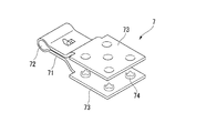
- FIG. 6 shows an example of such a crimp terminal 7.
- the crimp terminal 7 has sharp metal teeth 74 called a lance on both of two metal plates 73 (for example, a tin-plated copper plate) of about 10 mm square, in which the lead wire crimping portion 71 is connected to the connecting portion 72 so as to be opened and closed. Are arranged in a certain pattern and face each other.
- the conducting wire 6 is crimped to the conducting wire crimping portion 71, the protective layer 15, the reinforcing layer 14, and the conductive layer 11 are sandwiched between the lances 74 of the two metal plates 73, 73 and crushed with pliers or a hammer.
- the lance 74 breaks through the protective layer 15 and the reinforcing layer 14, and the lances 74 and 74 bite into the conductive layer 11. Further, since the lance 74 is arranged in the plane of the metal plate 73, the periphery of the portion where the lance 74 bites into the conductive layer 11 is covered with the metal plate 73. Thereby, the conductive layer 11 is reliably connected to the conductive wire 6, and the connection portion is protected by the metal plate 73. Further, since the crimp terminal 7 is firmly fixed by the reinforcing layer 14, the crimp terminal 7 is not detached from the conductive layer 11 made of a graphite sheet that is easily broken.
- the crimp terminal 7 When the crimp terminal 7 comes into contact with the electrolyte layer 12, the crimp terminal 7 also functions as an anode, so that the crimp terminal 7 is easily corroded. Therefore, when the crimp terminal 7 is in contact with the electrolyte layer 12, it is preferable to cut away the electrolyte layer 12 at a site serving as a discharge point or not to laminate in advance.
- the crimp terminal 7 is connected by causing the conductive layer 11 together with the protective layer 15 and the reinforcing layer 14 to bite into the metal teeth 74 of the crimp terminal 7 and then crimping the conductor 6 to the conductor crimp 71 of the crimp terminal 7. Also good. Further, in the crimp terminal 7 of FIG.
- each of the two metal plates 73 and 73 has five (center and four corners) lances 74 (in the upper metal plate 73, a recess on the back side of the lance 74 is illustrated.
- the number and arrangement of the metal teeth 74 can be changed as appropriate.
- FIG. 2 schematically shows an example of the second embodiment of the anticorrosion anode 10 of the present invention and an example of the anticorrosion structure of a concrete structure using the same.
- symbol 16 shows a through-hole.
- the conductive layer 11 used in the anticorrosion anode 10 of the present embodiment is provided with a large number of through holes 16 in the conductive layer 11 in preparation for the case where the gas generated during the corrosion protection by a large current is released.
- the only difference between the first embodiment and the second embodiment of the anticorrosion anode 10 is that the conductive layer 11 in FIG.
- Other components denoted by the same reference numerals as those in FIG. 1 indicate the same components in FIG.
- the reinforcing layer 14 is first laminated on the conductive layer 11 so that the conductive layer 11 is not damaged, and then both are perforated together. Therefore, in this embodiment, the through holes 16 are provided in both the conductive layer 11 and the reinforcing layer 14.
- the through-hole 16 may be in a state of being perforated halfway without penetrating the fiber base material of the reinforcing layer 14.
- a known method such as punching, laser beam, or drilling using a needle can be employed. Punching with a punch provides a hole with a relatively large diameter compared to drilling with a needle, but punching waste is generated. In the drilling using a laser beam, the drilling state can be arbitrarily set, but the apparatus is expensive. Therefore, perforation using a needle that does not generate punching waste in an inexpensive device is preferred.
- the perforation using the needle is preferably perforated from the graphite sheet side.
- the periphery of the hole is irregularly cleaved, and the piece that is cleaved on the surface of the graphite sheet rises.
- the graphite sheet particularly graphite produced by the expanding method used in this embodiment, may be broken because of its low tear strength. Further, even if the tear pieces are not torn, the return stress remains in the tear pieces, so that the through holes 16 are easily closed.
- the cleaved pieces rise similarly. However, in this case, since the periphery of the cleaved piece is entangled with the fiber of the fiber base material of the reinforcing layer 14, the through hole 16 is difficult to close.
- the punching by a needle hook is from the graphite sheet side
- the graphite sheet cannot be melted even if drilled from the graphite sheet side, but the fibers of the fiber base material can be melted.
- the perforated pieces are welded in a state of being entangled with the fibers of the fiber base material of the reinforcing layer 14, so that the through holes 16 are more difficult to close.
- the shape of the through hole 16 is not particularly limited as long as gas can pass therethrough.
- the density of the through holes 16 is related to the amount of gas generated during corrosion prevention and the size of the through holes 16. Therefore, it is preferable to perform a preliminary test to confirm the density of the through holes 16.
- the size of the through hole 16 is preferably in the range of about 0.1 to 1 mm in diameter when the shape is circular. If the size of the through hole 16 is smaller than this range, clogging is likely to occur, and the generated gas may not be allowed to escape smoothly. If the size of the through-hole 16 is larger than this range, punching punching by punching is adopted, so care must be taken in the processing of punching waste.
- Example 1 of the anticorrosion anode 10 was produced by the following procedure.
- a conductive layer 11 made of a graphite sheet manufactured by an expanding method having a thickness of 0.125 mm, a width of 340 mm, and a length of 1000 mm has a thickness of about 0.25 to 0.3 mm, a basis weight of 50 g / m 2 , a basis weight of 460 mm, and a length of 1000 mm.
- a reinforcing layer 14 made of a PP nonwoven fabric was laminated by dry lamination.
- the obtained laminate of the conductive layer 11 and the reinforcing layer 14 was punched from the conductive layer 11 side with a hot needle, and a large number of through holes 16 were formed in the conductive layer 11 and the reinforcing layer 14.
- a protective layer 15 was obtained by dry-laminating a polyvinyl fluoride film having a thickness of 40 ⁇ m and a width of 460 mm, which was colored gray by blending a pigment on the surface of the conductive layer 11 on which the reinforcing layer 14 was not laminated. In dry lamination, the adhesive was gravure coated in a dot shape.
- Example 1 of the anticorrosion anode 10 shown in FIG. 2 is such that the exposed surface of the electrolyte layer 12 is in close contact with the conductive layer 11 surface of the anticorrosion anode 10 so that the margins on both sides of the conductive layer 11 are uniform.
- Example 1 of the anticorrosion anode 10 shown in FIG. 2 is such that the exposed surface of the electrolyte layer 12 is in close contact with the conductive layer 11 surface of the anticorrosion anode 10 so that the margins on both sides of the conductive layer 11 are uniform.
- the actual resistance value was measured when the conductive layer 11 and the reinforcing layer 14 were laminated.
- a general tester was used, and the electrode terminal was brought into light contact with the graphite sheet surface.
- the measurement method includes points A to 100 mm every 100 mm along the one side (lower side in FIG. 3) of the conductive layer 11 from the origin O at the corner indicating the portion where the discharge point of the conductive layer 11 is to be provided.
- J is set along the opposite side of the conductive layer 11 (upper side in FIG. 3) to points O, E, and J, and points a, b, and c are set, and the resistance value between these two points is measured. did.
- Actually measured locations are Oa, Ob, Oc, E, which are considered to include fluctuation factors in the length direction between OA to OJ in the length direction every 100 mm. -B. Table 1 shows the measurement results.
- the resistance value between all the parts is 2 ⁇ or less, and the difference between the maximum value and the minimum value is 0.3 ⁇ . From this, the conductive layer 11 has a low resistance value in the horizontal direction, and when the drain point is provided at the corner, the difference in resistance value is small compared to the part near and far from the drain point. confirmed. Furthermore, when the conductive layer 11 is produced by the method described in the example of Patent Document 2, a feeding material made of a metal tape such as stainless steel is attached along the longitudinal direction of the conductive layer, and the conductive layer is discharged. It is preferable to reduce the difference in the energized state between the part far from the point and the part close to the point.
- the resistance value between 1000 mm may be about 4 ⁇ . From this, it was confirmed that the power supply material is unnecessary in the conductive layer 11 of this embodiment.
- a sample for the energization test shown in FIG. 4 was prepared by the following procedure, and a large current energization test was performed.
- Resin adhesive tapes 22 and 23 were attached to the lower end and the middle of the conductive layer 11 fixed to the resin plate 21 with an adhesive. No tape was applied to the upper end of the conductive layer 11 in order to connect the positive electrode of the power source using the alligator terminal 24. In that way, a strip-shaped exposed portion of 15 mm ⁇ 100 mm where no tape was applied was provided between the lower end tape 22 and the intermediate tape 23.
- This sample was immersed in a saturated calcium hydroxide aqueous solution containing 3% sodium chloride so that the intermediate tape 23 would be the boundary between the aqueous solution and air (draft line).
- a titanium electrode coated with platinum connected to the negative electrode of the power source was immersed in this aqueous solution so as to face the sample, and a constant current was passed between them.
- the reason why the tape 23 is affixed to the portion that becomes the water line is that the amount of current per unit area is constant by not changing the contact area between the aqueous solution and the strip-shaped exposed portion even when the water level of the aqueous solution changes due to the electrolytic reaction. It is for holding.
- the reason why the tape 22 is stuck to the lower end of this sample is to prevent the conductive layer 11 from being peeled off from the resin plate 21.
- a constant current was passed at a current value of 262.4 A / m 2 .
- This current value is the amount of current that can be energized in 20 minutes by promoting the integrated current amount (87.6 Ah / m 2 ) when energized at 10 mA / m 2 for one year.
- the influence on the conductive layer 11 due to other factors such as changes in temperature and humidity over a long period cannot be considered, it is considered that the condition is severe when considering only the corrosion resistance of the conductive layer 11 due to energization of a large current. .
- the voltage change at the time of applying a constant current is shown in FIG.
- the amount of accumulated current becomes unstable voltage from around beyond 52,205Ah / m 2, the voltage reaches 10V at which point 56,511Ah / m 2.
- the time when the voltage becomes unstable is 595 years, and the time when the voltage reaches 10 V is 645 years. From this, it was confirmed that the conductive layer 11 of the anticorrosion anode 10 of the present embodiment has extremely high corrosion resistance.
- Example 1 of the anticorrosion structure 1 was produced by the following procedure.
- the PE masking film of the electrolyte layer 12 of the obtained anticorrosion anode 10 of Example 1 was peeled off, and the exposed surface was attached to the concrete layer 3 in which the reinforcing bars 4 were embedded.
- the lead wire 6 with the crimp terminal 7 was prepared by crimping the lead wire 6 covered with the resin layer with the copper wire to the lead wire crimping portion 71 of the crimp terminal 7 (trade name Termi foil) shown in FIG.
- the conductive layer 11, the reinforcing layer 14, and the protective layer 15 were sandwiched between the crimp terminals 7 at one end of one side of the conductive layer 11 exposed at a width of 20 mm on both sides of the anticorrosion anode 10. Then, the two metal plates 73 and 73 of the crimp terminal 7 were struck with a hammer, and the lances 74 and 74 of the crimp terminal 7 were bitten into the conductive layer 11.
- the anticorrosion anode 10 was firmly fixed because the lances 74, 74 bite into both the conductive layer 11 and the reinforcing layer 14, and was securely connected electrically.
- the conducting wire 6 was connected to the positive electrode of a power supply, and the negative electrode of the power supply was connected to the reinforcing bar in concrete, and Example 1 of the anticorrosion structure 1 shown in FIG. 2 was produced.
- a drain point is provided at one end of one side of the conductive layer 11 exposed on both sides, but a drain point may be provided at one end on both sides of the conductive layer 11.
- the two discharge points are preferably provided so as to face each other across the diagonal line.
- the drain point may be provided at the center of the conductive layer 11 exposed on the side.
- the crimp terminal 7 that contacts the conductive layer 11 and connects the lead wire 6 uses two metal plates 73, 73 connected in a foldable manner at the lead wire crimping portion 71, but the two metal plates May be connected so as to be foldable with one side as an axis that is not connected to the lead wire crimping part.
- the amount of work on the construction site can be reduced as much as possible.
- the difference in energization state between the part far from the drain point of the conductive layer and the part near the drain point of the conductive layer can be reduced without using a power supply material, the voltage to be energized can be kept low, and by electrolysis of water and chlorine compounds It is possible to provide an anticorrosion anode that generates less gas and is capable of anticorrosion for a long period of time, and an anticorrosion structure and an anticorrosion method for a concrete structure using the anode.
- Corrosion-proof structure of the present invention 3 Surface layer (concrete layer) 4 Protected body (rebar) 5 External power supply 6 Circuit wiring (conductor) 7 Crimp terminal 10 Anticorrosion anode 11 Conductive layer 12 Electrolyte layer 13 Adhesive layer 14 Reinforcing layer 15 Protective layer 16 Through hole 21 Resin plates 22 and 23 Tape (resin adhesive tape) 24 Alligator terminal 71 Conductive wire crimping part 72 Connecting part 73 Metal plate 74 Metal teeth (lance)
Landscapes
- Engineering & Computer Science (AREA)
- Chemical & Material Sciences (AREA)
- Materials Engineering (AREA)
- Mechanical Engineering (AREA)
- Metallurgy (AREA)
- Organic Chemistry (AREA)
- Structural Engineering (AREA)
- Civil Engineering (AREA)
- Life Sciences & Earth Sciences (AREA)
- Architecture (AREA)
- Textile Engineering (AREA)
- General Life Sciences & Earth Sciences (AREA)
- Paleontology (AREA)
- Mining & Mineral Resources (AREA)
- General Engineering & Computer Science (AREA)
- Physics & Mathematics (AREA)
- Hydrology & Water Resources (AREA)
- Electromagnetism (AREA)
- Environmental & Geological Engineering (AREA)
- Prevention Of Electric Corrosion (AREA)
- Laminated Bodies (AREA)
Abstract
Description
外部電源方式は、直流電源装置の正極を防食用陽極に、負極を被防食体の鋼材に、それぞれ導体で接続して電気回路を作り、この電気回路により防食電流を防食用陽極から鋼材へ流すカソード防食である。
一方、白金がコートされたチタン線をコンクリート面に間隔をおいて取り付け、コンクリート全面を導電性の塗料でコーティングする方法が開発されている。しかし、この方法は、導電塗膜とコンクリートの接触面の状態により電位分布が不均一となり、電気化学的反応により導電塗膜が劣化して剥がれやすい、という問題がある。
しかし、この方法は、コンクリート構造物表面における充填材層の設置予定箇所にマスキングテープを貼って接着剤を縞模様に塗布する。その後、マスキングテープを剥がして、炭素繊維シートを付着させる。炭素繊維シートの貼付後に、充填材層の設置予定箇所に2本の管体を貫通させ、一方の管体を通して空気を排出しながら、他方の管体を通して充填材を炭素繊維シートとコンクリート構造物表面との間に注入する。その後、さらに炭素繊維シートの上から含浸用接着剤を含浸させる。
この様にして接着剤層と充填材層をストライプ状に設ける作業は、橋梁の床盤などの構造物の裏面に処理を施す場合が多い防食工事の現場においては作業を頭上で行う必要があるので、重労働となる。
特許文献2の提案では、陽極が工場で作製されており、現場での陽極の設置に際し、シート状に成形された炭素素材をコンクリートの表面に電解質層で貼着するだけなので、陽極の設置が極めて容易である。
しかも、防食する部位のコンクリートの全面に電解質層が貼着されるので、セメントベースの充填材層がストライプ状に設けられる場合に比べて、電荷の移動が格段に効率良く行われる。また、陽極面が耐酸化金属で被覆されていないので、コスト面で有利であり、不働態被膜が破壊されることもない。
しかし、給電材の設置の手間は、特許文献1の方法に比べれば改善されるとしても、工場における陽極の作製に手間がかかるので、できれば給電材の設置を省略したいという希望がある。
また、本発明の目的の一つは、給電材を用いなくても導電層の排流点から遠い部分と近い部分の通電状態の差を小さくすることである。これにより、本発明は、通電する電圧を低く抑えて、水や塩素化合物の電気分解による気体の発生が少なく、長期間の電気防食が可能な防食用陽極、それを用いたコンクリート構造物の防食構造および防食方法を提供する。
本発明の第1の態様は、グラファイトシートからなる導電層の一方の面に繊維基材からなる補強層が接着剤層を用いて積層され、電解質を含む樹脂がシート状に成形され、導電層および被防食体の表面層に貼着可能な粘着力を有する電解質層がその粘着力により導電層の他方の面に貼着された外部電源による防食用陽極であって、導電層は、電解質層に接する側の面における任意の二点間の抵抗値が常に4Ω以下である防食用陽極である。
本発明の第2の態様は、導電層が気体の透過が可能な多数の連通孔を有する第1の態様の防食用陽極である。
本発明の第3の態様は、補強層の外面が不透水性の保護層で覆われた第1の態様または第2の態様の防食用陽極である。
本発明の第4の態様は、電解質層の外面が不透水性の剥離紙で覆われた第1の態様~第3の態様のいずれかの防食用陽極である。
本発明の第5の態様は、第1の態様~第4の態様のいずれかの防食用陽極が電解質層を用いてコンクリート構造物の表面に貼着され、防食用陽極の導電層が外部電源の正極に接続され、外部電源の負極が被防食体に接続されているコンクリート構造物の防食構造である。
本発明の第6の態様は、少なくとも前記導電層と前記補強層の両者に金属の歯を有する端子の金属の歯が食い込むことで、前記導電層が前記外部電源の正極に接続された第5の態様のコンクリート構造物の防食構造である。
本発明の第7の態様は、第5の態様または第6の態様のコンクリート構造物の防食構造を用いて、防食用陽極の導電層と前記被防食体との間に電圧を印加して防食電流を流すコンクリート構造物の防食方法である。
そして、水平方向の抵抗値が低く排流点を隅部に設けた場合であっても、排流点から近い部位と遠い部位の抵抗値の差が小さい導電層と、シート状に成形されたゲル電解質と、が広い面積で均一に密着するので、給電材を用いなくても電気防食を行う際の被防食体の表面層の電位分布が均一となる。
給電材を設置する必要がないので、陽極の製造が容易となり、長期間通電すると給電材近傍の導電層が劣化する可能性があるという問題も解決することができる。
そして、電解質層を導電層に貼着し、電解質層の導電層が貼着されていない面を用いて被防食体の表面層に陽極を貼着することができる。従って、陽極が軽いことにも起因して、防食用陽極を設置するための現場での作業量を大幅に低減することができる。
従って、本発明の防食用陽極は、印加する電圧が小さくても防食効果が得られるので、高価で設置に手間のかかる電源装置を必要とする商用電源を用いなくとも、太陽電池、燃料電池、乾電池などの独立した電源を用いることにより防食が可能である。
本発明の第4の態様の防食用陽極によれば、第1の態様~第3の態様の防食用陽極の効果に加えて、電解質層の溶媒の蒸発、物理的損傷、汚れ、他の物品との意図しない接着を防止できる。
本発明の第6の態様の防食構造によれば、第5の態様の防食構造の効果に加えて、施工現場での配線作業が容易で、長期間にわたる通電不良の可能性がないコンクリート構造物の防食構造が得られる。
本発明の第7の態様の防食方法によれば、第5の態様または第6の態様の防食構造と同様な効果に加えて、防食に大きな電流を用いる場合でも印加する電圧を低く抑えることができるので、長期間安定した電気防食を行うことができる。
図1に本発明の防食用陽極10の一例およびそれを用いたコンクリート構造物の防食構造の一例を模式的に示す。
図1において、符号1は本発明の防食構造、符号3は表面層(コンクリート層)、符号4は被防食体(鉄筋)、符号5は外部電源、符号6は回路配線(導線)、符号10は本発明の防食用陽極、符号11は導電層、符号12は電解質層、符号13は接着剤層、符号14は補強層、符号15は保護層を示す。
なお、「貼着」とは、物体同士が粘着または接着により一体化することを意味する。粘着とは、意図的な界面での剥離は可能であるが、自然な状態では剥離しない接着強度で物体同士が一体化することを意味する。接着とは、界面での剥離が不能な接着強度で物体同士が一体化することを意味する。
本発明に用いる導電層11は、外部電源5により供給される電流を、電解質層12を介して、被防食体4の表面層3に均一に供給する面状電極である。
この導電層11は、電解質層12に接する面における任意の二点間の抵抗値(以下、単に「二点間の抵抗値」という場合がある。)が常に4Ω以下である。
グラファイトシートは、耐熱性や耐薬品性、熱伝導体性や電気伝導性に優れるので、熱伝導材、耐熱シール材、燃料電池のガス拡散体などに広く使用されている。
グラファイトシートは、水平方向(層に沿う方向)の体積抵抗率が垂直方向(層を貫通する方向)の体積抵抗率に比べて著しく低い。また、通電時に発生する酸素や塩素などの気体および電解質溶液に対する耐久性(耐食性)が高い。
なお、一般的には、「シート」は厚い膜状物を意味し、「フィルム」は、薄い膜状物を意味する。ただし、本明細書においては、厚みに関係することなく「シート」および「フィルム」を用いる。
実際にステンレステープの給電材を、導電性接着剤を用いて導電層の長手方向に沿って設けると、排流点から遠い部分と近い部分の通電状態の差を小さくすることができる。この時に用いるステンレステープは、厚さ30μm、幅4mm、長さ1000mmである。このステンレステープは、実際の抵抗値が4Ω程度と意外に大きい。従って、導電層11による通電状態が均一となるためには、導電性接着剤の接触抵抗を考慮すれば、二点間の抵抗値が常に4Ω以下であればよい。
導電層11に用いるグラファイトシートは、例えば、以下の様な方法で製造されるものが好ましい。
しかし、エキスパンド法においては、膨張化処理時に酸化剤を使用する。酸化剤は、水などで洗浄されるが、完全に取り除くことは難しい。従って、長期間使用する場合、残留していた酸化剤が徐々に浸出し、導電層11に接続された排流端子を腐食させる可能性がある。その様な場合に備えて、排流端子は、白金、金、銀、銅、チタン、ステンレススチールなどの酸化されにくい、または、酸化されても腐食しにくい金属を用いることが好ましい。
さらに、鱗片状グラファイト同士の結合が弱いため、鱗片状グラファイト同士の剥離が起こりやすい。従って、グラファイトシート単体は、取り扱い方法によっては、破損や破れが生じることがあり、慎重な取り扱いが必要である。
高分子フィルム熱分解法では、原料としてグラファイト化反応が可能である縮合系芳香族高分子フィルムを用いることが好ましい。それらの中でも芳香族系ポリイミドフィルムがより好ましい。
グラファイト化は、まず、縮合系芳香族高分子フィルムを、窒素やアルゴンなどの不活性ガス中で、最高温度が好ましくは1000℃~1200℃とする予備熱処理を行う。
さらに、ローラやプレス板を用いて圧延を行って、シートの膜厚、密度、表面状態などの均一化を図る。これにより、単結晶グラファイトと同様の特性を持つ、高品質で、柔軟性と強靱性に富み、熱伝導性と電気伝導性に優れたグラファイトシートが得られる。
また、より高品質のグラファイトシートを得るためには、圧延時に、グラファイトシート表面への水蒸気を噴霧したり、別途製造したグラファイトからなる耐熱性の保護シートを重ね合わせたりすることが好ましい。
高分子熱分解法によるグラファイトシートは、導電性や熱伝導性に優れた性質を持っているが、その厚さは、原料の厚さと炭化過程における熱分解反応の進み易さから1mm以下となる。高分子熱分解法によるグラファイトシートは、その厚さが薄くても、高い導電性により二点間の抵抗値を低くすることができる。
このグラファイトシートの製造方法は、平均粒径1~30μmの炭素短繊維とポリビニルアルコール等の有機バインダーを含む抄造媒体との混合物を、例えば、丸網抄紙機等で抄いて抄造シートとする。抄造シートを加熱加圧して、シート状中間体を作製する。その後、その中間体に、加熱すると炭素化する樹脂(たとえばフェノール樹脂、エポキシ樹脂、フラン樹脂、メラミン樹脂、ピッチなど)を含浸させて前駆体繊維シートとする。
炭素短繊維を構成する炭素繊維としては、ポリアクリロニトリル(PAN)系、ピッチ系、レーヨン系等の炭素繊維を用いることができる。これらの炭素繊維のなかでも、機械的強度に優れ、適度な柔軟性を有し、取扱性に優れた多孔質炭素シートが得られることから、PAN系やピッチ系の炭素繊維を用いることが好ましい。
本形態例の防食用陽極10においては、コスト面で有利であることを優先させて、導電層11として、エキスパンド法によるグラファイトシートを用いる。
電解質層12は、粘着力を有し、その粘着力により導電層11に貼着されている。また、電解質層12は、その粘着力によりコンクリート層や塗料被膜などの被防食体4の表面に存在するイオン透過性の表面層3に防食用陽極10を貼着させる粘着剤層でもある。
電解質層12がゲル電解質層であると、防食用陽極10を被防食体4の表面層、例えばコンクリート層3に貼着する場合に、コンクリート層3の微小な凹凸に電解質層12の一部が入り込んで、高い接着強度と広い接触面積で電解質層12が接触して貼着させることができるので好ましい。
電解質層12の大きさは、電荷移動の観点から、導電層11と同じ大きさであることが好ましい。これにより、電解質層12が、電解質層12の全面が導電層11の全面に正確に重ねられた状態で、導電層11に貼着されると、電荷移動の観点から無駄な面がないので好ましい。粘着の観点からは、導電層11より大きくてもよいし、排流点を設ける際の作業性の観点からは、導電層11よりも小さくてもよい。
電解質層12に用いるゲル電解質層の樹脂マトリックスは、凝集力を高めるために、架橋剤にて架橋処理を施したり、重合性単量体と架橋性単量体とを重合して架橋させたりしておくことが好ましい。高分子鎖が三次元に架橋された樹脂マトリックスは、溶媒や湿潤剤を保持する能力に優れる。これにより、樹脂マトリックス内に電解質塩を分子レベルで溶解した状態で保持することが可能である。
そのような溶媒としては、水;メタノール、エタノール、イソプロパノール等のアルコール類;メチルセロソルブ、エチルセロソルブ、ブチルセロソルブなどのセロソルブ類;N,N-ジメチルホルムアミド、N,N-ジメチルアセトアミド、N,N’-ジメチル-2-イミダゾリジノン、N-メチル-2-ピロリドンなどのアミド類;スルホラン等のスルホン類;ジメチルスルホキシド等のスルホキシド類;等を挙げることができる。これらの溶媒は、混合して用いてもよい。
ハイドロゲル層は、樹脂マトリックス内に電解質塩を分子レベルで水に溶解した状態で保持することが可能である。即ち、電解質水溶液により電荷の移動速度が速くなり、ハイドロゲル層に柔軟性と粘着性とを容易に付与することができる。
ハイドロゲル層中の電解質塩の含有率は、0.01~20質量%であることが好ましく、0.1~10重量%であることがより好ましい。この範囲より高いと、電解質塩の水に対する完全な溶解が困難となってハイドロゲル層内に結晶として析出したり、他の成分の溶解を阻害したりすることがある。この範囲より低いと、イオン伝導性に劣ることがある。
これらのうち、多価アルコール類は、水分を保持する作用に加え、ハイドロゲル層に弾力性も付与するので好ましい。多価アルコール類のうち、長期保水性の面でグリセリンが特に好ましい。多価アルコール類は、これらの中から1種または2種以上を選択して使用することができる。多価アルコール類の内、常温で液状のものは、ハイドロゲル層の弾力性向上や製造時の取扱性に優れるのでより好ましい。ハイドロゲル層の弾力性を上げる必要がある場合には、酸化チタン、炭酸カルシウム、タルク等の公知の充填剤を添加してもよい。
また、ハイドロゲル層のpHを調整するために、NaOHやKOH等のアルカリを含んでいてもよい。
電解質層12に用いるハイドロゲル層には、必要に応じて、防腐剤、防黴剤、防錆剤、酸化防止剤、安定剤、界面活性剤、着色剤等を適宜添加してもよい。
電解質層12として、予めシートに成形されたハイドロゲル層を用いることもできる。
この場合は、ハイドロゲル層が粘着性を有するので、ハイドロゲル層を、そのまま導電層11に貼着することができる。この方法は、ロールに巻かれた導電層11およびロールに巻かれたハイドロゲル層を用いて、防食用陽極10を連続的に生産する場合に好ましい。
導電層11が枚葉に裁断されている場合は、重合性単量体、架橋性単量体、湿潤剤、重合開始剤および電解質塩を水中に溶解または分散させ、導電層11の上に塗布してゾル状の電解質層を形成し、その後にラジカル重合することによって、ゲル化させてもよい。
電解質層12にハイドロゲル層を用いる場合は、外側の露出面からの水の蒸発や粘着力による塵埃や異物の付着を防止するために、露出面に不透水性の剥離紙を積層することが好ましい。通常、市販されているハイドロゲル層は、両面に不透水性の剥離紙が積層されているので、これをそのまま用いてもよい。
不透水性の剥離紙は、樹脂フィルムにシリコーン等の剥離剤を塗布したものでもよいが、剥離剤がハイドロゲル層面に移行するおそれがある。一方、ハイドロゲル層は、ポリエチレンやポリプロピレンなどのポリオレフィンとは、剥離可能に粘着するので、ポリオレフィンのフィルムをそのまま剥離紙として積層することが好ましい。
補強層14は、取り扱い方法によっては、破損や破れが生じることがあり、慎重な取り扱いが求められるグラファイトシートを取り扱いやすくするために補強する層である。特に、本形態例の防食用陽極10の導電層11には、安価であるが、鱗片状グラファイト同士の剥離が起こりやすいエキスパンド法によるグラファイトシートを用いるので、補強層14でグラファイトシートを補強することは重要である。補強層14として不織布を用いると、不織布の高い引裂き強度により破れやすいグラファイトシートを補強することができるので好ましい。
従って、補強層14としては、ガラス繊維、動物性繊維、植物性繊維、合成樹脂繊維等の繊維を織布、不織布、編布、紙などのシートに加工した繊維基材を用いることができる。これらの繊維基材の内、合成樹脂繊維からなる繊維基材は、引裂き強度に優れ、耐食性が高いので好ましい。
これらの繊維基材は、不織布に加工されていると、垂直方向と水平方向に通気性を有し、厚みや空隙を容易に選択できるので好ましい。また、通気性を確保して厚みを持たせることができるので、引裂き強度に優れる。
補強層14の上に後述する保護層15が積層される場合、防食時に発生する気体は、保護層15を透過して逃げる。保護層15の気体透過では十分でない場合は、補強層14の端面から気体を逃がしてもよい。この場合、補強層14の端面は薄いので、埃や塵等により目詰まりしやすい。補強層14が導電層11よりも幅が広いと、導電層11に積層されない部分が通気口となるので、目詰まりしにくくなる。
これらの樹脂のうち、PEやPP等のポリオレフィン樹脂は、耐食性が高く、入手が容易で、コスト面で有利なので好ましい。
通常、グラファイトシートを補強する場合は、熱可塑性樹脂層を熱圧着して積層する。グラファイトシートと熱可塑性樹脂層との間に余計な層を介在させないためである。しかし、本発明においては、熱可塑性樹脂からなる繊維基材を熱圧着すると、垂直方向と水平方向の両方の通気性が損なわれるので、好ましくない。
一方、ドライラミネートは、接着剤をグラビアロールで塗布するので、そのようなことは起きない。接着剤層13によって垂直方向の通気性が阻害されるおそれがあるときは、塗布量を小さくすることで容易に調整できる。場合によっては、点状や格子状のパターンで接着剤を塗布することもできる。
保護層15は、樹脂層を、ドライラミネート、押出ラミネート、または押出樹脂を接着層としてフィルムを積層するサンドラミネートで積層することができる。
これらの樹脂の内、フッ素系樹脂は、汚染防止性や耐候性に優れ、多数の孔を設けなくても、10mA~30mA程度の電流を流して防食する場合に発生する酸素や塩素などの気体を透過させるので、好ましい。
保護層15は、着色されていてもよいし、文字情報や模様等の意匠が付されていてもよい。特に、保護層15がコンクリート層3の表面の色に似た灰色系統の色に着色されていることは、防食用陽極10が目立たないので、好ましい。
保護層15の上に粘着層を有するマスキングフィルムを積層しておくことは、防食用陽極10をコンクリート層3に設置する際に汚れや破損が生じないので、好ましい。
被防食体4がコンクリート層3中に埋設されている場合も、防食が可能である。コンクリート層3中の極めて小さい空隙中には水分を含んだゲル状の物質がある。このゲル状の物質中に含まれるイオンとしては、OH-、Na+、Ca2+、K+などが主なものである。また、防食の必要性が高い海に近い場所にある構造物のコンクリート層には、塩化ナトリウムが浸み込んでくる。
コンクリート層3は、インピーダンスが著しく大きい固体の電解質層であり、これらのイオンによるイオン伝導性を有する層として機能する。そして、コンクリート層3は、乾燥により空気中へ水分を放出したり、あるいは、雨水や気温の日較差により空気中の水分を吸収したりするので、コンクリート層3が絶乾状態になることはない。
従って、イオンがこのクラックや微細な孔が存在する部分を移動できることにより、このクラックや微細な孔が存在する部分はイオン伝導性となる。これにより、本発明の防食用陽極10を塗料の被膜に貼着して防食が可能である。そして、この防食は、このクラックや微細な孔が存在する部分に対して行えばよいので、極めて狭い面積を防食することになる。したがって、防食用陽極10からクラックや微細な孔が存在する部分への電子の供給量が小さくても、極めて有効な防食が可能となる。
また、ハイドロゲル層は、樹脂マトリックスを有する。これにより、塗料被膜を有する金属を防食する場合に、防食用陽極10を被防食体となる金属の表面に直接接着させても導電層11が金属に接触しないので、短絡することがない。
従って、防食用陽極10を剥き出しの金属の表面に直接貼着する、または、防食用陽極10を金属の表面に存在する錆等のイオン透過性の酸化物被膜からなる表面層に貼着することにより、被防食体となる金属を防食できる。
回路配線6は、アノード溶解に対する耐腐食性を有するものが好ましく、例えば、炭素、チタン、ステンレス、白金、タンタル、ジルコニウム、ニオビウム、ニッケル、モネルやインコネル等のニッケル合金が挙げられる。これらのうち、チタンは、入手しやすく、広い範囲の電位に亘ってアノード溶解に耐性があるので、好ましい。
また、アルミ線や銅線などのアノード溶解に耐性がない回路配線6でも、樹脂層で被覆して用いることができる。
電源等の回路に接続する排流点は、導電性接着剤で回路配線6を導電層11に接着してもよいが、端子を用いることが好ましい。このような端子として、回路配線6を圧着可能な圧着端子が、より好ましい。そして、この圧着端子が鋭い金属の歯を有していて、その歯が導電層11に食い込むことができると、作業が容易で、確実な電気的接続が得られるので好ましい。その様な圧着端子に回路配線6を圧着して、導電層11と補強層14の両方に圧着端子の歯を食い込ませる。これにより、合成樹脂の繊維基材からなる補強層14は引裂き強度が大きいので、圧着端子が強固に固着される。このため、圧着端子が回路配線6を圧着する部位では、少なくとも補強層14を導電層11上に積層することが好ましい。さらに、この部位には、導電層11上に積層された補強層14上に、さらに保護層15を積層してもよい。
そのような圧着端子としては、例えば、タイコエレクトロニクスジャパン合同会社(旧タイコエレクトロニクスアンプ合同会社)からターミホイル(TERMI-FOIL)の商品名で販売されている。
また、圧着端子7の接続は、保護層15、補強層14とともに導電層11を圧着端子7の金属の歯74に食い込ませてから、導線6を圧着端子7の導線圧着部71に圧着してもよい。
また、図6の圧着端子7では、二枚の各金属板73、73は、それぞれ5つ(中央および4隅)のランス74を有する(上側の金属板73ではランス74の裏側の窪みが図示されている)が、金属の歯74の個数および配置は、適宜変更可能である。
本形態例の防食用陽極10に用いる導電層11は、大電流による防食時に発生する気体を逃がす場合に備えて、導電層11に多数の貫通孔16が設けられている。
防食用陽極10の第一の形態例と第二の形態例が異なる点は、図2における導電層11が貫通孔16を有する点のみである。それ以外の図1と同じ符号が付されたものは、図2においても同じものを示すので、説明を省略する。
しかし、腐食が進行している鉄筋を防食するために脱塩処理や再アルカリ化が可能な電流量が必要とされる場合には、防食時に発生する気体を逃がす必要がある。
あるいは、炭素短繊維を樹脂炭化物で結着させたグラファイトシートを導電層11に用いる場合であっても、より高い透気性が必要な場合は、貫通孔16を設けてもよい。
貫通孔16の形成には、パンチ打ち抜き、レーザー光線、針を用いた穿孔など公知の方法を採用することができる。パンチによる打ち抜き穿孔は、針を用いた穿孔に比べて比較的径の大きな孔が得られるが、打ち抜きの屑が発生する。レーザー光線を用いた穿孔は、穿孔状態を任意に設定できるが、装置が高価である。従って、安価な装置に打ち抜きの屑が発生しない針を用いる穿孔が好ましい。
一方、グラファイトシート側から穿孔すると、同じように裂開片が盛り上がる。しかし、この場合は、裂開片は、その周囲が補強層14の繊維基材の繊維に絡まるので、貫通孔16が閉鎖されにくい。
熱針を用いた穿孔は、グラファイトシート側から穿孔してもグラファイトシートを溶融させることはできないが、繊維基材の繊維を溶融させることはできる。
穿孔時に繊維基材の繊維を溶融させると、裂開片の周囲が補強層14の繊維基材の繊維に絡まった状態で溶着されるので、貫通孔16がより閉鎖されにくくなる。
貫通孔16の密度は、防食時に発生する気体の量と貫通孔16の大きさに関係する。そのため、予備試験を行い貫通孔16の密度を確認することが好ましい。通常、貫通孔16の大きさは、形状を円形としたとき、貫通孔16の直径が0.1~1mm程度の範囲にあることが好ましい。貫通孔16の大きさがこの範囲より小さいと、目詰まりしやすく、発生する気体を円滑に逃がせないことがある。貫通孔16の大きさがこの範囲より大きいと、パンチによる打ち抜き穿孔を採用することになるので、打ち抜きの屑の処理に注意が必要である。
以下の手順により、防食用陽極10の実施例1を作製した。
厚さ0.125mm、幅340mm、長さ1000mmのエキスパンド法で製造したグラファイトシートからなる導電層11に厚さ約0.25~0.3mm、目付50g/m2、幅460mm、長さ1000mmのPP製不織布からなる補強層14をドライラミネートで積層した。
得られた導電層11と補強層14の積層体を導電層11側から熱針で穿孔し、導電層11と補強層14に多数の貫通孔16を形成した。
導電層11の補強層14が積層されていない面に顔料を配合して灰色に着色した厚さ40μm、幅460mmのポリフッ化ビニルフィルムをドライラミネートして保護層15とした。ドライラミネートに際し、接着剤は、点状にグラビアコートした。
測定方法は、図3に示すように、導電層11の排流点を設ける予定部位を示す隅部の原点Oから導電層11の一辺(図3では下辺)に沿って100mmごとに点A~Jを、また導電層11の対辺(図3では上辺)に沿って点O、E、Jに対向する位置にそれぞれ点a、b、cを設定し、これらの二点間の抵抗値を測定した。
実際に測定した個所は、O-AからO-Jまでの100mmごとの長さ方向の部位間と、幅方向の変動要因を含むと考えられるO-a、O-b、O-c、E-b間とした。表1にその測定結果を示す。
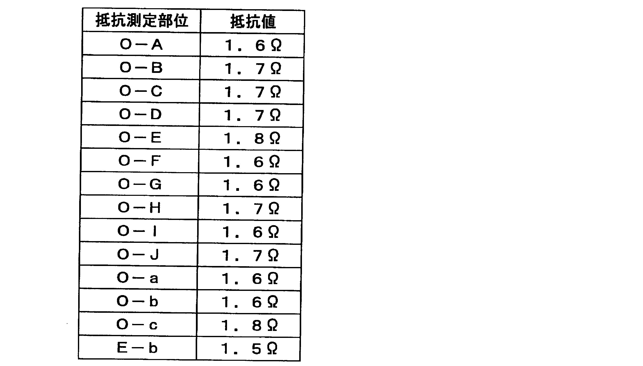
さらに、特許文献2の実施例に記載された方法で導電層11を作製した場合は、導電層の長手方向に沿ってステンレスなどの金属テープからなる給電材を貼り付けて、導電層の排流点から遠い部分と近い部分の通電状態の差を小さくすることが好ましい。そして、実際にステンレステープの給電材を設けた場合、接触抵抗や導電性接着剤の抵抗があるため、同様の測定を行うと1000mm間の抵抗値が4Ω程度となることがある。このことから、本形態例の導電層11では、給電材が不要であることが確認された。
以下の手順で図4に示す通電試験のサンプルを作製し、大電流の通電試験を実施した。
接着剤で樹脂板21に固定した導電層11の下端と中間には、樹脂製粘着テープ22、23を貼った。導電層11の上端には、ワニ口端子24を用いて電源の正極を接続するためにテープを貼らなかった。
その様にして、下端のテープ22と中間のテープ23の間には、テープを貼らない15mm×100mmの帯状の露出部を設けた。
喫水線となる部位にテープ23を貼った理由は、電解反応により水溶液の水位が変化した場合においても、水溶液と帯状の露出部との接触面積を変化させないことで、単位面積当たりの電流量を一定に保持するためである。また、このサンプルの下端にテープ22を貼った理由は、導電層11が樹脂板21から剥がれるのを防止するためである。
得られた実施例1の防食用陽極10の電解質層12のPEのマスキングフィルムを剥がして、露出した面を鉄筋4が埋設されているコンクリート層3に貼着した。
銅線を樹脂層で被覆した導線6を図6に示す圧着端子7(商品名ターミホイル)の導線圧着部71に圧着して、圧着端子7付導線6を用意した。防食用陽極10の両側辺に幅20mmで露出した導電層11の片側の一端に、導電層11と補強層14と保護層15を圧着端子7で挟んだ。そして、圧着端子7の二枚の金属板73、73をハンマーでたたいて、圧着端子7のランス74、74を導電層11に食い込ませた。防食用陽極10は、ランス74、74が導電層11と補強層14の両方に食い込んでいるので強固に固定され、電気的にも確実に接続されていた。
そして、導線6を電源の正極に接続し、電源の負極をコンクリート中の鉄筋に接続して、図2に示す防食構造1の実施例1を作製した。
本形態例では、両側辺に露出した導電層11の片側の一端に排流点を設けたが、導電層11の両側の一端にそれぞれ排流点を設けてもよい。この場合、二つの排流点は、対角線を挟んで対向するように設けることが好ましい。また、排流点は、側辺に露出した導電層11の中央に設けてもよい。
また、導電層11に接触して導線6を接続する圧着端子7は、二枚の金属板73、73が導線圧着部71で折重ね可能に連結したものを用いたが、二枚の金属板が導線圧着部に連結しない一辺を軸として折重ね可能に連結されたものを用いてもよい。
3 表面層(コンクリート層)
4 被防食体(鉄筋)
5 外部電源
6 回路配線(導線)
7 圧着端子
10 防食用陽極
11 導電層
12 電解質層
13 接着剤層
14 補強層
15 保護層
16 貫通孔
21 樹脂板
22、23 テープ(樹脂製粘着テープ)
24 ワニ口端子
71 導線圧着部
72 連結部
73 金属板
74 金属の歯(ランス)
Claims (7)
- グラファイトシートからなる導電層の一方の面に繊維基材からなる補強層が接着剤層を用いて積層され、電解質を含む樹脂がシート状に成形され、前記導電層および被防食体の表面層に貼着可能な粘着力を有する電解質層がその粘着力により前記導電層の他方の面に貼着された外部電源による防食用陽極であって、前記導電層は、前記電解質層に接する側の面における任意の二点間の抵抗値が常に4Ω以下である防食用陽極。
- 前記導電層が気体の透過が可能な多数の連通孔を有する請求項1に記載の防食用陽極。
- 前記補強層の外面が不透水性の保護層で覆われた請求項1に記載の防食用陽極。
- 前記電解質層の外面が不透水性の剥離紙で覆われた請求項1に記載の防食用陽極。
- 請求項1ないし4のいずれかに記載の防食用陽極が前記電解質層を用いてコンクリート構造物の表面に貼着され、前記防食用陽極の前記導電層が外部電源の正極に接続され、外部電源の負極が被防食体に接続されているコンクリート構造物の防食構造。
- 少なくとも前記導電層と前記補強層の両者に金属の歯を有する端子の金属の歯が食い込むことで、前記導電層が前記外部電源の正極に接続された請求項5に記載のコンクリート構造物の防食構造。
- 請求項5に記載のコンクリート構造物の防食構造を用いて、前記防食用陽極の前記導電層と前記被防食体との間に電圧を印加して防食電流を流すコンクリート構造物の防食方法。
Priority Applications (4)
| Application Number | Priority Date | Filing Date | Title |
|---|---|---|---|
| EP15774117.4A EP3128040B1 (en) | 2014-03-31 | 2015-03-31 | Cathode for preventing corrosion, and concrete structure corrosion prevention structure and corrosion prevention method employing same |
| CN201580017016.6A CN106164338B (zh) | 2014-03-31 | 2015-03-31 | 防腐蚀用阳极、使用其的混凝土结构物的防腐蚀结构及防腐蚀方法 |
| US15/300,177 US10227699B2 (en) | 2014-03-31 | 2015-03-31 | Anode for preventing corrosion, and concrete structure corrosion prevention structure and corrosion prevention method employing same |
| KR1020167026003A KR102270325B1 (ko) | 2014-03-31 | 2015-03-31 | 방식용 양극, 그것을 사용한 콘크리트 구조물의 방식 구조 및 방식 방법 |
Applications Claiming Priority (2)
| Application Number | Priority Date | Filing Date | Title |
|---|---|---|---|
| JP2014-071412 | 2014-03-31 | ||
| JP2014071412A JP6238449B2 (ja) | 2014-03-31 | 2014-03-31 | 防食用陽極、それを用いたコンクリート構造物の防食構造および防食方法 |
Publications (1)
| Publication Number | Publication Date |
|---|---|
| WO2015152247A1 true WO2015152247A1 (ja) | 2015-10-08 |
Family
ID=54240566
Family Applications (1)
| Application Number | Title | Priority Date | Filing Date |
|---|---|---|---|
| PCT/JP2015/060138 Ceased WO2015152247A1 (ja) | 2014-03-31 | 2015-03-31 | 防食用陽極、それを用いたコンクリート構造物の防食構造および防食方法 |
Country Status (7)
| Country | Link |
|---|---|
| US (1) | US10227699B2 (ja) |
| EP (1) | EP3128040B1 (ja) |
| JP (1) | JP6238449B2 (ja) |
| KR (1) | KR102270325B1 (ja) |
| CN (1) | CN106164338B (ja) |
| TW (1) | TWI665335B (ja) |
| WO (1) | WO2015152247A1 (ja) |
Cited By (3)
| Publication number | Priority date | Publication date | Assignee | Title |
|---|---|---|---|---|
| CN106757052A (zh) * | 2016-12-12 | 2017-05-31 | 华北水利水电大学 | 一种采用强电解质溶液抑制水工钢结构件的腐蚀的方法 |
| CN112031036A (zh) * | 2020-08-11 | 2020-12-04 | 中铁二局第二工程有限公司 | 一种高盐岩隧道弃渣场生态防护系统及生态防护方法 |
| EP3854913A4 (en) * | 2018-09-21 | 2022-03-30 | Asahi Kasei Kabushiki Kaisha | LAMINATE, LAMINATE STORAGE METHOD, LAMINATE SHIPPING METHOD, PROTECTIVE LAMINATE AND PACKAGING THEREOF |
Families Citing this family (7)
| Publication number | Priority date | Publication date | Assignee | Title |
|---|---|---|---|---|
| CN105525296B (zh) * | 2015-12-24 | 2018-04-10 | 天津工业大学 | 一种金属防腐蚀方法 |
| WO2018203221A1 (en) * | 2017-05-01 | 2018-11-08 | Hashemi Farzad | Cathodic protection of metal substrates |
| US11591697B2 (en) | 2017-09-07 | 2023-02-28 | Carrier Corporation | Corrosion protection system for heating ventalation air conditioning refrigeration |
| KR101988247B1 (ko) | 2017-11-03 | 2019-06-12 | 한국건설기술연구원 | 양극금속선이 구비된 탄소섬유 텍스타일 보강재 및 이를 이용한 철근콘크리트 구조물의 보수보강 방법 |
| JP7089653B2 (ja) * | 2020-12-02 | 2022-06-23 | デンカ株式会社 | 電気化学的処理システム及び電極用ユニットパネル |
| JP7307425B2 (ja) * | 2021-04-26 | 2023-07-12 | 株式会社パワーバンクシステム | 電気防食方法 |
| US12428736B2 (en) | 2022-09-16 | 2025-09-30 | Vector Corrosion Technologies Ltd. | Method and apparatus for cathodic protection of steel in a concrete structure located in an ionically conductive liquid |
Citations (4)
| Publication number | Priority date | Publication date | Assignee | Title |
|---|---|---|---|---|
| JPS6050461U (ja) * | 1983-09-13 | 1985-04-09 | 出光興産株式会社 | 圧着端子 |
| JPH06136572A (ja) * | 1992-10-29 | 1994-05-17 | Nippon Boshoku Kogyo Kk | コンクリート構造物上の電気防食用金属皮膜の結線方法 |
| JP2002220685A (ja) * | 2001-01-24 | 2002-08-09 | Civil Renewale Kk | 鋼材の防食方法 |
| WO2013031663A1 (ja) * | 2011-08-26 | 2013-03-07 | 藤森工業株式会社 | 補助陽極、それを用いたコンクリート構造物の防食構造および防食方法 |
Family Cites Families (8)
| Publication number | Priority date | Publication date | Assignee | Title |
|---|---|---|---|---|
| JPS6372891A (ja) * | 1986-09-12 | 1988-04-02 | Mitsubishi Cable Ind Ltd | 防食テ−プ |
| JPS63184567U (ja) * | 1987-05-21 | 1988-11-28 | ||
| US4812212A (en) | 1987-09-08 | 1989-03-14 | Harco Technologies Corporation | Apparatus for cathodically protecting reinforcing members and method for installing same |
| JPH0577863U (ja) * | 1992-03-24 | 1993-10-22 | 日本電気株式会社 | 圧着端子の構造 |
| JP3792646B2 (ja) | 2002-12-13 | 2006-07-05 | オリエンタル建設株式会社 | 防食補強コンクリート組立体、その防食方法及び組立方法 |
| CN1867700B (zh) | 2003-10-10 | 2010-11-10 | 戴维·惠特莫尔 | 覆盖材料内钢的阴极保护 |
| JP5501131B2 (ja) * | 2010-07-16 | 2014-05-21 | 藤森工業株式会社 | 防食構造 |
| US9074288B2 (en) * | 2011-07-12 | 2015-07-07 | Jarden Zinc Products, LLC | Galvanic panel with compliant construction |
-
2014
- 2014-03-31 JP JP2014071412A patent/JP6238449B2/ja active Active
-
2015
- 2015-03-31 CN CN201580017016.6A patent/CN106164338B/zh active Active
- 2015-03-31 TW TW104110424A patent/TWI665335B/zh active
- 2015-03-31 KR KR1020167026003A patent/KR102270325B1/ko active Active
- 2015-03-31 EP EP15774117.4A patent/EP3128040B1/en active Active
- 2015-03-31 WO PCT/JP2015/060138 patent/WO2015152247A1/ja not_active Ceased
- 2015-03-31 US US15/300,177 patent/US10227699B2/en active Active
Patent Citations (4)
| Publication number | Priority date | Publication date | Assignee | Title |
|---|---|---|---|---|
| JPS6050461U (ja) * | 1983-09-13 | 1985-04-09 | 出光興産株式会社 | 圧着端子 |
| JPH06136572A (ja) * | 1992-10-29 | 1994-05-17 | Nippon Boshoku Kogyo Kk | コンクリート構造物上の電気防食用金属皮膜の結線方法 |
| JP2002220685A (ja) * | 2001-01-24 | 2002-08-09 | Civil Renewale Kk | 鋼材の防食方法 |
| WO2013031663A1 (ja) * | 2011-08-26 | 2013-03-07 | 藤森工業株式会社 | 補助陽極、それを用いたコンクリート構造物の防食構造および防食方法 |
Non-Patent Citations (1)
| Title |
|---|
| See also references of EP3128040A4 * |
Cited By (3)
| Publication number | Priority date | Publication date | Assignee | Title |
|---|---|---|---|---|
| CN106757052A (zh) * | 2016-12-12 | 2017-05-31 | 华北水利水电大学 | 一种采用强电解质溶液抑制水工钢结构件的腐蚀的方法 |
| EP3854913A4 (en) * | 2018-09-21 | 2022-03-30 | Asahi Kasei Kabushiki Kaisha | LAMINATE, LAMINATE STORAGE METHOD, LAMINATE SHIPPING METHOD, PROTECTIVE LAMINATE AND PACKAGING THEREOF |
| CN112031036A (zh) * | 2020-08-11 | 2020-12-04 | 中铁二局第二工程有限公司 | 一种高盐岩隧道弃渣场生态防护系统及生态防护方法 |
Also Published As
| Publication number | Publication date |
|---|---|
| JP2015193869A (ja) | 2015-11-05 |
| KR20160138962A (ko) | 2016-12-06 |
| TW201600649A (zh) | 2016-01-01 |
| EP3128040A1 (en) | 2017-02-08 |
| EP3128040B1 (en) | 2023-05-03 |
| KR102270325B1 (ko) | 2021-06-28 |
| TWI665335B (zh) | 2019-07-11 |
| CN106164338B (zh) | 2019-06-18 |
| US10227699B2 (en) | 2019-03-12 |
| EP3128040A4 (en) | 2018-01-10 |
| US20170130341A1 (en) | 2017-05-11 |
| JP6238449B2 (ja) | 2017-11-29 |
| CN106164338A (zh) | 2016-11-23 |
Similar Documents
| Publication | Publication Date | Title |
|---|---|---|
| JP6238449B2 (ja) | 防食用陽極、それを用いたコンクリート構造物の防食構造および防食方法 | |
| JP6047493B2 (ja) | 補助陽極、それを用いたコンクリート構造物の防食構造および防食方法 | |
| KR100331344B1 (ko) | 이온전도제,전기화학적활성금속의음극방식시스템및이에따라방식처리된구조물 | |
| JP5275701B2 (ja) | プリント配線基板用アルミニウム材及びその製造方法 | |
| JP5507696B2 (ja) | 塗工液、導電性塗工膜、蓄電装置用電極板及び蓄電装置 | |
| US20210013551A1 (en) | Electrical energy storage device, an electrolyte for use in an electrical energy storage device, and a method of preparing the device | |
| US10944129B2 (en) | Conducting polymers | |
| JP6141654B2 (ja) | 防食構造および防食方法 | |
| JP5887401B2 (ja) | 粘着性ハイドロゲル、及びコンクリート構造物の電気防食方法 | |
| Yiming et al. | Stretchable ionic conductors: balancing mechanical properties and ionic conductivity | |
| CN105063994A (zh) | 一种碳纤维的表面处理方法 | |
| JP5501131B2 (ja) | 防食構造 | |
| Du et al. | A Hofmeister effect induced hydrogel electrolyte–electrode interfacial adhesion enhancement strategy for energy-efficient and mechanically robust redoxcapacitors | |
| Fu et al. | Self-healing hydrogels in flexible energy storage devices: mechanisms, applications, and prospects | |
| US9461278B2 (en) | Method for providing a stretchable power source and device | |
| JP4993970B2 (ja) | 鉄筋コンクリート構造物の電気防食構造 | |
| JP6274797B2 (ja) | 導電性シートの面状陽電極 | |
| JP4292282B2 (ja) | 電気防食用陽極ユニット及びこれを用いたコンクリート構造物 | |
| US11123457B2 (en) | Nerve contact devices | |
| JPS62500389A (ja) | 陰極防食のための触媒性ポリマ−電極およびこれからなる陰極防食システム |
Legal Events
| Date | Code | Title | Description |
|---|---|---|---|
| 121 | Ep: the epo has been informed by wipo that ep was designated in this application |
Ref document number: 15774117 Country of ref document: EP Kind code of ref document: A1 |
|
| ENP | Entry into the national phase |
Ref document number: 20167026003 Country of ref document: KR Kind code of ref document: A |
|
| WWE | Wipo information: entry into national phase |
Ref document number: 15300177 Country of ref document: US |
|
| NENP | Non-entry into the national phase |
Ref country code: DE |
|
| REEP | Request for entry into the european phase |
Ref document number: 2015774117 Country of ref document: EP |
|
| WWE | Wipo information: entry into national phase |
Ref document number: 2015774117 Country of ref document: EP |