WO2015152369A1 - 空気調和機 - Google Patents
空気調和機 Download PDFInfo
- Publication number
- WO2015152369A1 WO2015152369A1 PCT/JP2015/060452 JP2015060452W WO2015152369A1 WO 2015152369 A1 WO2015152369 A1 WO 2015152369A1 JP 2015060452 W JP2015060452 W JP 2015060452W WO 2015152369 A1 WO2015152369 A1 WO 2015152369A1
- Authority
- WO
- WIPO (PCT)
- Prior art keywords
- refrigerant
- accumulator
- air conditioner
- compressor
- temperature sensor
- Prior art date
- Legal status (The legal status is an assumption and is not a legal conclusion. Google has not performed a legal analysis and makes no representation as to the accuracy of the status listed.)
- Ceased
Links
Images

Classifications
-
- F—MECHANICAL ENGINEERING; LIGHTING; HEATING; WEAPONS; BLASTING
- F24—HEATING; RANGES; VENTILATING
- F24F—AIR-CONDITIONING; AIR-HUMIDIFICATION; VENTILATION; USE OF AIR CURRENTS FOR SCREENING
- F24F11/00—Control or safety arrangements
-
- F—MECHANICAL ENGINEERING; LIGHTING; HEATING; WEAPONS; BLASTING
- F25—REFRIGERATION OR COOLING; COMBINED HEATING AND REFRIGERATION SYSTEMS; HEAT PUMP SYSTEMS; MANUFACTURE OR STORAGE OF ICE; LIQUEFACTION SOLIDIFICATION OF GASES
- F25B—REFRIGERATION MACHINES, PLANTS OR SYSTEMS; COMBINED HEATING AND REFRIGERATION SYSTEMS; HEAT PUMP SYSTEMS
- F25B49/00—Arrangement or mounting of control or safety devices
- F25B49/02—Arrangement or mounting of control or safety devices for compression type machines, plants or systems
-
- C—CHEMISTRY; METALLURGY
- C09—DYES; PAINTS; POLISHES; NATURAL RESINS; ADHESIVES; COMPOSITIONS NOT OTHERWISE PROVIDED FOR; APPLICATIONS OF MATERIALS NOT OTHERWISE PROVIDED FOR
- C09K—MATERIALS FOR MISCELLANEOUS APPLICATIONS, NOT PROVIDED FOR ELSEWHERE
- C09K5/00—Heat-transfer, heat-exchange or heat-storage materials, e.g. refrigerants; Materials for the production of heat or cold by chemical reactions other than by combustion
- C09K5/02—Materials undergoing a change of physical state when used
- C09K5/04—Materials undergoing a change of physical state when used the change of state being from liquid to vapour or vice versa
- C09K5/041—Materials undergoing a change of physical state when used the change of state being from liquid to vapour or vice versa for compression-type refrigeration systems
- C09K5/044—Materials undergoing a change of physical state when used the change of state being from liquid to vapour or vice versa for compression-type refrigeration systems comprising halogenated compounds
- C09K5/045—Materials undergoing a change of physical state when used the change of state being from liquid to vapour or vice versa for compression-type refrigeration systems comprising halogenated compounds containing only fluorine as halogen
-
- F—MECHANICAL ENGINEERING; LIGHTING; HEATING; WEAPONS; BLASTING
- F25—REFRIGERATION OR COOLING; COMBINED HEATING AND REFRIGERATION SYSTEMS; HEAT PUMP SYSTEMS; MANUFACTURE OR STORAGE OF ICE; LIQUEFACTION SOLIDIFICATION OF GASES
- F25B—REFRIGERATION MACHINES, PLANTS OR SYSTEMS; COMBINED HEATING AND REFRIGERATION SYSTEMS; HEAT PUMP SYSTEMS
- F25B1/00—Compression machines, plants or systems with non-reversible cycle
-
- F—MECHANICAL ENGINEERING; LIGHTING; HEATING; WEAPONS; BLASTING
- F25—REFRIGERATION OR COOLING; COMBINED HEATING AND REFRIGERATION SYSTEMS; HEAT PUMP SYSTEMS; MANUFACTURE OR STORAGE OF ICE; LIQUEFACTION SOLIDIFICATION OF GASES
- F25B—REFRIGERATION MACHINES, PLANTS OR SYSTEMS; COMBINED HEATING AND REFRIGERATION SYSTEMS; HEAT PUMP SYSTEMS
- F25B13/00—Compression machines, plants or systems, with reversible cycle
-
- F—MECHANICAL ENGINEERING; LIGHTING; HEATING; WEAPONS; BLASTING
- F25—REFRIGERATION OR COOLING; COMBINED HEATING AND REFRIGERATION SYSTEMS; HEAT PUMP SYSTEMS; MANUFACTURE OR STORAGE OF ICE; LIQUEFACTION SOLIDIFICATION OF GASES
- F25B—REFRIGERATION MACHINES, PLANTS OR SYSTEMS; COMBINED HEATING AND REFRIGERATION SYSTEMS; HEAT PUMP SYSTEMS
- F25B31/00—Compressor arrangements
- F25B31/002—Lubrication
- F25B31/004—Lubrication oil recirculating arrangements
-
- F—MECHANICAL ENGINEERING; LIGHTING; HEATING; WEAPONS; BLASTING
- F25—REFRIGERATION OR COOLING; COMBINED HEATING AND REFRIGERATION SYSTEMS; HEAT PUMP SYSTEMS; MANUFACTURE OR STORAGE OF ICE; LIQUEFACTION SOLIDIFICATION OF GASES
- F25B—REFRIGERATION MACHINES, PLANTS OR SYSTEMS; COMBINED HEATING AND REFRIGERATION SYSTEMS; HEAT PUMP SYSTEMS
- F25B43/00—Arrangements for separating or purifying gases or liquids; Arrangements for vaporising the residuum of liquid refrigerant, e.g. by heat
- F25B43/006—Accumulators
-
- F—MECHANICAL ENGINEERING; LIGHTING; HEATING; WEAPONS; BLASTING
- F25—REFRIGERATION OR COOLING; COMBINED HEATING AND REFRIGERATION SYSTEMS; HEAT PUMP SYSTEMS; MANUFACTURE OR STORAGE OF ICE; LIQUEFACTION SOLIDIFICATION OF GASES
- F25B—REFRIGERATION MACHINES, PLANTS OR SYSTEMS; COMBINED HEATING AND REFRIGERATION SYSTEMS; HEAT PUMP SYSTEMS
- F25B43/00—Arrangements for separating or purifying gases or liquids; Arrangements for vaporising the residuum of liquid refrigerant, e.g. by heat
- F25B43/02—Arrangements for separating or purifying gases or liquids; Arrangements for vaporising the residuum of liquid refrigerant, e.g. by heat for separating lubricants from the refrigerant
-
- C—CHEMISTRY; METALLURGY
- C09—DYES; PAINTS; POLISHES; NATURAL RESINS; ADHESIVES; COMPOSITIONS NOT OTHERWISE PROVIDED FOR; APPLICATIONS OF MATERIALS NOT OTHERWISE PROVIDED FOR
- C09K—MATERIALS FOR MISCELLANEOUS APPLICATIONS, NOT PROVIDED FOR ELSEWHERE
- C09K2205/00—Aspects relating to compounds used in compression type refrigeration systems
- C09K2205/10—Components
- C09K2205/12—Hydrocarbons
- C09K2205/122—Halogenated hydrocarbons
-
- C—CHEMISTRY; METALLURGY
- C09—DYES; PAINTS; POLISHES; NATURAL RESINS; ADHESIVES; COMPOSITIONS NOT OTHERWISE PROVIDED FOR; APPLICATIONS OF MATERIALS NOT OTHERWISE PROVIDED FOR
- C09K—MATERIALS FOR MISCELLANEOUS APPLICATIONS, NOT PROVIDED FOR ELSEWHERE
- C09K2205/00—Aspects relating to compounds used in compression type refrigeration systems
- C09K2205/10—Components
- C09K2205/12—Hydrocarbons
- C09K2205/126—Unsaturated fluorinated hydrocarbons
-
- C—CHEMISTRY; METALLURGY
- C09—DYES; PAINTS; POLISHES; NATURAL RESINS; ADHESIVES; COMPOSITIONS NOT OTHERWISE PROVIDED FOR; APPLICATIONS OF MATERIALS NOT OTHERWISE PROVIDED FOR
- C09K—MATERIALS FOR MISCELLANEOUS APPLICATIONS, NOT PROVIDED FOR ELSEWHERE
- C09K2205/00—Aspects relating to compounds used in compression type refrigeration systems
- C09K2205/22—All components of a mixture being fluoro compounds
-
- C—CHEMISTRY; METALLURGY
- C09—DYES; PAINTS; POLISHES; NATURAL RESINS; ADHESIVES; COMPOSITIONS NOT OTHERWISE PROVIDED FOR; APPLICATIONS OF MATERIALS NOT OTHERWISE PROVIDED FOR
- C09K—MATERIALS FOR MISCELLANEOUS APPLICATIONS, NOT PROVIDED FOR ELSEWHERE
- C09K2205/00—Aspects relating to compounds used in compression type refrigeration systems
- C09K2205/34—The mixture being non-azeotropic
-
- F—MECHANICAL ENGINEERING; LIGHTING; HEATING; WEAPONS; BLASTING
- F25—REFRIGERATION OR COOLING; COMBINED HEATING AND REFRIGERATION SYSTEMS; HEAT PUMP SYSTEMS; MANUFACTURE OR STORAGE OF ICE; LIQUEFACTION SOLIDIFICATION OF GASES
- F25B—REFRIGERATION MACHINES, PLANTS OR SYSTEMS; COMBINED HEATING AND REFRIGERATION SYSTEMS; HEAT PUMP SYSTEMS
- F25B2313/00—Compression machines, plants or systems with reversible cycle not otherwise provided for
- F25B2313/027—Compression machines, plants or systems with reversible cycle not otherwise provided for characterised by the reversing means
- F25B2313/02741—Compression machines, plants or systems with reversible cycle not otherwise provided for characterised by the reversing means using one four-way valve
-
- F—MECHANICAL ENGINEERING; LIGHTING; HEATING; WEAPONS; BLASTING
- F25—REFRIGERATION OR COOLING; COMBINED HEATING AND REFRIGERATION SYSTEMS; HEAT PUMP SYSTEMS; MANUFACTURE OR STORAGE OF ICE; LIQUEFACTION SOLIDIFICATION OF GASES
- F25B—REFRIGERATION MACHINES, PLANTS OR SYSTEMS; COMBINED HEATING AND REFRIGERATION SYSTEMS; HEAT PUMP SYSTEMS
- F25B2313/00—Compression machines, plants or systems with reversible cycle not otherwise provided for
- F25B2313/031—Sensor arrangements
- F25B2313/0314—Temperature sensors near the indoor heat exchanger
-
- F—MECHANICAL ENGINEERING; LIGHTING; HEATING; WEAPONS; BLASTING
- F25—REFRIGERATION OR COOLING; COMBINED HEATING AND REFRIGERATION SYSTEMS; HEAT PUMP SYSTEMS; MANUFACTURE OR STORAGE OF ICE; LIQUEFACTION SOLIDIFICATION OF GASES
- F25B—REFRIGERATION MACHINES, PLANTS OR SYSTEMS; COMBINED HEATING AND REFRIGERATION SYSTEMS; HEAT PUMP SYSTEMS
- F25B2313/00—Compression machines, plants or systems with reversible cycle not otherwise provided for
- F25B2313/031—Sensor arrangements
- F25B2313/0315—Temperature sensors near the outdoor heat exchanger
-
- F—MECHANICAL ENGINEERING; LIGHTING; HEATING; WEAPONS; BLASTING
- F25—REFRIGERATION OR COOLING; COMBINED HEATING AND REFRIGERATION SYSTEMS; HEAT PUMP SYSTEMS; MANUFACTURE OR STORAGE OF ICE; LIQUEFACTION SOLIDIFICATION OF GASES
- F25B—REFRIGERATION MACHINES, PLANTS OR SYSTEMS; COMBINED HEATING AND REFRIGERATION SYSTEMS; HEAT PUMP SYSTEMS
- F25B2400/00—General features or devices for refrigeration machines, plants or systems, combined heating and refrigeration systems or heat-pump systems, i.e. not limited to a particular subgroup of F25B
- F25B2400/12—Inflammable refrigerants
- F25B2400/121—Inflammable refrigerants using R1234
-
- F—MECHANICAL ENGINEERING; LIGHTING; HEATING; WEAPONS; BLASTING
- F25—REFRIGERATION OR COOLING; COMBINED HEATING AND REFRIGERATION SYSTEMS; HEAT PUMP SYSTEMS; MANUFACTURE OR STORAGE OF ICE; LIQUEFACTION SOLIDIFICATION OF GASES
- F25B—REFRIGERATION MACHINES, PLANTS OR SYSTEMS; COMBINED HEATING AND REFRIGERATION SYSTEMS; HEAT PUMP SYSTEMS
- F25B2500/00—Problems to be solved
- F25B2500/28—Means for preventing liquid refrigerant entering into the compressor
-
- F—MECHANICAL ENGINEERING; LIGHTING; HEATING; WEAPONS; BLASTING
- F25—REFRIGERATION OR COOLING; COMBINED HEATING AND REFRIGERATION SYSTEMS; HEAT PUMP SYSTEMS; MANUFACTURE OR STORAGE OF ICE; LIQUEFACTION SOLIDIFICATION OF GASES
- F25B—REFRIGERATION MACHINES, PLANTS OR SYSTEMS; COMBINED HEATING AND REFRIGERATION SYSTEMS; HEAT PUMP SYSTEMS
- F25B2600/00—Control issues
- F25B2600/21—Refrigerant outlet evaporator temperature
-
- F—MECHANICAL ENGINEERING; LIGHTING; HEATING; WEAPONS; BLASTING
- F25—REFRIGERATION OR COOLING; COMBINED HEATING AND REFRIGERATION SYSTEMS; HEAT PUMP SYSTEMS; MANUFACTURE OR STORAGE OF ICE; LIQUEFACTION SOLIDIFICATION OF GASES
- F25B—REFRIGERATION MACHINES, PLANTS OR SYSTEMS; COMBINED HEATING AND REFRIGERATION SYSTEMS; HEAT PUMP SYSTEMS
- F25B2600/00—Control issues
- F25B2600/25—Control of valves
- F25B2600/2513—Expansion valves
-
- F—MECHANICAL ENGINEERING; LIGHTING; HEATING; WEAPONS; BLASTING
- F25—REFRIGERATION OR COOLING; COMBINED HEATING AND REFRIGERATION SYSTEMS; HEAT PUMP SYSTEMS; MANUFACTURE OR STORAGE OF ICE; LIQUEFACTION SOLIDIFICATION OF GASES
- F25B—REFRIGERATION MACHINES, PLANTS OR SYSTEMS; COMBINED HEATING AND REFRIGERATION SYSTEMS; HEAT PUMP SYSTEMS
- F25B2700/00—Sensing or detecting of parameters; Sensors therefor
- F25B2700/21—Temperatures
- F25B2700/2113—Temperatures of a suction accumulator
-
- F—MECHANICAL ENGINEERING; LIGHTING; HEATING; WEAPONS; BLASTING
- F25—REFRIGERATION OR COOLING; COMBINED HEATING AND REFRIGERATION SYSTEMS; HEAT PUMP SYSTEMS; MANUFACTURE OR STORAGE OF ICE; LIQUEFACTION SOLIDIFICATION OF GASES
- F25B—REFRIGERATION MACHINES, PLANTS OR SYSTEMS; COMBINED HEATING AND REFRIGERATION SYSTEMS; HEAT PUMP SYSTEMS
- F25B2700/00—Sensing or detecting of parameters; Sensors therefor
- F25B2700/21—Temperatures
- F25B2700/2115—Temperatures of a compressor or the drive means therefor
- F25B2700/21151—Temperatures of a compressor or the drive means therefor at the suction side of the compressor
-
- F—MECHANICAL ENGINEERING; LIGHTING; HEATING; WEAPONS; BLASTING
- F25—REFRIGERATION OR COOLING; COMBINED HEATING AND REFRIGERATION SYSTEMS; HEAT PUMP SYSTEMS; MANUFACTURE OR STORAGE OF ICE; LIQUEFACTION SOLIDIFICATION OF GASES
- F25B—REFRIGERATION MACHINES, PLANTS OR SYSTEMS; COMBINED HEATING AND REFRIGERATION SYSTEMS; HEAT PUMP SYSTEMS
- F25B2700/00—Sensing or detecting of parameters; Sensors therefor
- F25B2700/21—Temperatures
- F25B2700/2115—Temperatures of a compressor or the drive means therefor
- F25B2700/21152—Temperatures of a compressor or the drive means therefor at the discharge side of the compressor
-
- F—MECHANICAL ENGINEERING; LIGHTING; HEATING; WEAPONS; BLASTING
- F25—REFRIGERATION OR COOLING; COMBINED HEATING AND REFRIGERATION SYSTEMS; HEAT PUMP SYSTEMS; MANUFACTURE OR STORAGE OF ICE; LIQUEFACTION SOLIDIFICATION OF GASES
- F25B—REFRIGERATION MACHINES, PLANTS OR SYSTEMS; COMBINED HEATING AND REFRIGERATION SYSTEMS; HEAT PUMP SYSTEMS
- F25B2700/00—Sensing or detecting of parameters; Sensors therefor
- F25B2700/21—Temperatures
- F25B2700/2117—Temperatures of an evaporator
Definitions
- the present invention relates to an air conditioner using a non-azeotropic refrigerant mixture.
- an HFC refrigerant having a high global warming potential (GWP) is known, and is a pseudo-azeotropic refrigerant HFC-R410A and a single refrigerant.
- HFC-R32 etc. are mainly used.
- a refrigeration cycle apparatus using a non-azeotropic refrigerant mixture in which an HFO refrigerant having a low GWP, for example, HFO-1234yf or HFO-1234ze and an R32 refrigerant is mixed has been proposed. (For example, refer to Patent Document 1).
- the HFC-R32 has a characteristic that it has a characteristic that the pressure loss when the refrigerant passes through the refrigerant pipe in the refrigeration cycle circuit is small, so that it has a characteristic of easily evaporating, but has a problem of high GWP.
- HFO-1234yf and HFO-1234ze are low in GWP, but have a problem that the pressure loss is large when the refrigerant passes through the refrigerant pipe in the refrigeration cycle circuit, and the evaporation capacity is greatly reduced.
- a conventional air conditioner using a pseudo-azeotropic refrigerant such as HFC-R410A or a single refrigerant such as HFC-R32 the dryness of the refrigerant at the inlet of the accumulator connected to the suction side of the compressor during normal operation By controlling the pressure reducing device so that is 1 or more, liquid refrigerant is not stored in the accumulator. For this reason, a conventional air conditioner using a pseudo-azeotropic refrigerant such as HFC-R410A or a single refrigerant such as HFC-R32 has an accumulator side end of the refrigerant pipe connecting the accumulator and the compressor inlet.
- An oil return hole (small hole) that protrudes into the accumulator and prevents the refrigerating machine oil from accumulating in the accumulator is formed at a position located below the accumulator in the range where the refrigerant pipe is disposed in the accumulator.
- a conventional air conditioner performs control to store the liquid refrigerant in the accumulator when the refrigerant dryness cannot be ensured to be 1 or more transiently. For this reason, when the refrigerant dryness becomes less than 1, liquid refrigerant is sucked into the compressor together with the refrigerating machine oil from the oil return hole, so that the suction pressure loss of the compressor becomes large and the performance of the air conditioner deteriorates. There was a problem of ending up.
- the present invention has been made to solve the above-described problems, and is an air conditioner that uses a non-azeotropic refrigerant mixture, and achieves high performance even when liquid refrigerant is stored in the accumulator.
- the purpose is to obtain an air conditioner that can be used.
- An air conditioner includes a refrigeration cycle circuit in which a compressor, a condenser, a decompression device, an evaporator, and an accumulator are connected by a refrigerant pipe, and a control device that controls an opening degree of the decompression device,
- the suction pipe which is a refrigerant pipe connecting the suction port of the compressor and the accumulator, has an end portion on the side connected to the accumulator protruding into the accumulator, so that the refrigeration cycle circuit has a non-azeotropic refrigerant mixture and a freezer.
- an oil return hole is formed at a position higher than the central portion of the accumulator in a range of the suction pipe disposed inside the accumulator.
- the opening degree of the decompression device is controlled so that the dryness of the refrigerant flowing into the accumulator is less than 1.
- the non-azeotropic refrigerant mixture is enclosed in the refrigeration cycle circuit, and the dryness of the refrigerant flowing into the accumulator is less than 1. For this reason, the refrigerant having a high boiling point among the refrigerants constituting the non-azeotropic refrigerant mixture can be preferentially stored in the accumulator. For example, when a non-azeotropic refrigerant mixture in which HFO-1234yf or HFO-1234ze is mixed with an R32 refrigerant is used, HFO-1234yf or HFO-1234ze having a high boiling point can be stored in the accumulator.
- the circulating refrigerant composition can be higher in HFC-R32 than the enclosed refrigerant composition. For this reason, the efficiency of a refrigerating cycle circuit improves and the performance deterioration of the air conditioner at the time of using a non-azeotropic refrigerant mixture can be prevented.
- an oil return hole is formed at a position higher than the central portion of the accumulator in the range of the intake pipe disposed inside the accumulator.
- the present invention can provide a high-performance air conditioner that uses a non-azeotropic refrigerant mixture.
- FIG. 1 is a refrigerant circuit diagram showing an air conditioner according to an embodiment of the present invention.
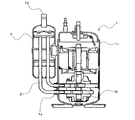
- FIG. 2 is a longitudinal sectional view showing a compressor and an accumulator of the air conditioner.
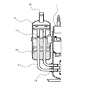
- FIG. 3 is a principal part enlarged view (longitudinal sectional view) showing the vicinity of the accumulator of the air conditioner.
- the solid line arrow indicates the refrigerant flow direction during the heating operation
- the broken line arrow indicates the refrigerant flow direction during the cooling operation.
- an air conditioner 100 includes a compressor 1 that compresses refrigerant, a four-way valve 6 that switches a refrigerant circulation direction during cooling operation and heating operation, and during cooling operation.
- Condenser outdoor heat exchanger 3 that operates as an evaporator during heating operation
- decompression device 4 for example, an electronically controlled expansion valve
- a refrigerant pipe is connected to the indoor heat exchanger 5 that operates as an evaporator at the time of heating and as a condenser at the time of heating operation, and an accumulator 2 that separates the liquid refrigerant and the gas refrigerant and supplies the gas refrigerant to the compressor 1.
- a refrigeration cycle circuit is provided. That is, the refrigeration cycle circuit of the air conditioner 100 during the cooling operation includes the compressor 1, the outdoor heat exchanger 3 that operates as a condenser, the decompression device 4, the indoor heat exchanger 5 that operates as an evaporator, and The accumulator 2 is configured to be annularly connected by a refrigerant pipe. Further, the refrigeration cycle circuit of the air conditioner 100 during heating operation includes a compressor 1, an indoor heat exchanger 5 that operates as a condenser, a decompression device 4, an outdoor heat exchanger 3 that operates as an evaporator, and The accumulator 2 is configured to be annularly connected by a refrigerant pipe.
- a non-azeotropic refrigerant mixture in which a low-boiling refrigerant and a high-boiling refrigerant are mixed is enclosed.
- HFC-R32 is used as the low boiling point refrigerant
- HFO-1234yf or HFO-1234ze is used as the high boiling point refrigerant.
- an outdoor fan 9 is provided in the outdoor heat exchanger 3, and an indoor fan 8 (for example, a cross flow fan) is provided in the indoor heat exchanger 5.
- an indoor fan 8 for example, a cross flow fan
- a part of the indoor heat exchanger 5 is operated as an evaporator to dehumidify the indoor air
- the other of the indoor heat exchanger 5 A reheat dehumidifying solenoid valve 7 is also provided for operating a part of the air as a condenser to heat the room air after dehumidification and return it to the room.
- a compressor intake refrigerant temperature sensor 10 that is provided in a refrigerant pipe on the refrigerant inflow side of the accumulator 2 and detects the temperature of the refrigerant flowing through the portion
- the compressor 1 Compressor discharge refrigerant temperature sensor 11 for detecting the temperature of the refrigerant flowing through the location, which is provided in the discharge-side piping, and provided in, for example, an intermediate portion of the outdoor heat exchanger 3, and the refrigerant flowing through the outdoor heat exchanger 3
- the outdoor heat exchanger refrigerant temperature sensor 12 that detects the temperature and the indoor heat exchanger refrigerant that is provided in, for example, an intermediate portion of the indoor heat exchanger 5 and detects the temperature of the refrigerant flowing through the indoor heat exchanger 5.
- a temperature sensor 13 is provided.
- Each of these sensors, the four-way valve 6, the pressure reducing device 4, the reheat dehumidifying electromagnetic valve 7, the indoor fan 8, and the outdoor fan 9 are electrically connected to the controller 16. That is, the control device 16 can receive the detection value of the above-described sensor, and can control the four-way valve 6, the decompression device 4, the reheat dehumidifying electromagnetic valve 7, the indoor fan 8, and the outdoor fan 9 independently. It has become.
- the compressor intake refrigerant temperature sensor 10, the compressor discharge refrigerant temperature sensor 11, the outdoor heat exchanger refrigerant temperature sensor 12, and the indoor heat exchanger refrigerant temperature sensor 13 indicate the temperature of the refrigerant pipe. By detecting, it is the structure which detects the temperature of a refrigerant
- the indoor side heat exchanger refrigerant temperature sensor 13 (a sensor for detecting the temperature of the refrigerant flowing through the evaporator) during the cooling operation and the outdoor heat exchanger refrigerant temperature sensor 12 (the refrigerant flowing through the evaporator) during the heating operation.
- the sensor for detecting the temperature of the first refrigerant corresponds to the first refrigerant temperature sensor in the present invention.
- the compressor suction refrigerant temperature sensor 10 corresponds to the second refrigerant temperature sensor in the present invention.
- the sensor 10, the compressor discharge refrigerant temperature sensor 11, and the outdoor heat exchanger refrigerant temperature sensor 12 are accommodated in the outdoor unit 15.
- the indoor side heat exchanger 5, the reheat dehumidifying electromagnetic valve 7, the indoor side blower 8, and the indoor side heat exchanger refrigerant temperature sensor 13 are accommodated in the indoor side unit 14.
- the control device 16 may be stored in the outdoor unit 15, may be stored in the indoor unit 14, or may be stored separately in the outdoor unit 15 and the indoor unit 14.
- the suction port 1 a of the compressor 1 and the accumulator 2 are connected by a suction pipe 21.
- the compressor 1 according to the present embodiment is a high-pressure compressor that discharges the refrigerant compressed by the compression mechanism portion 1b into the sealed container 1c.
- the compressor 1 is provided with two rotary type compression mechanism parts 1b. Therefore, in the present embodiment, the suction port of each compression mechanism portion 1 b and the accumulator 2 are connected by the two suction pipes 21.
- the structure of the compression mechanism part 1b of the compressor 1 is not limited to a rotary type, and the number of the compression mechanism parts 1b is not limited to two.
- the suction pipe 21 has an end portion on the side connected to the accumulator 2 protruding into the accumulator 2. More specifically, in this embodiment, an L-shaped pipe is used as the suction pipe 21, and the suction pipe 21 protrudes upward from the lower part of the accumulator 2 into the accumulator 2. Yes. As shown in FIG. 3, an oil return hole 19 that is, for example, a small hole is formed at a position higher than the central portion of the accumulator 2 in a range of the suction pipe 21 disposed inside the accumulator 2.
- the air conditioner 100 operates so that a refrigerant having a dryness of less than 1 flows into the accumulator 2 from the accumulator suction pipe 18 and the liquid refrigerant is stored in the accumulator 2. For this reason, it is preferable to form the oil return hole 19 at a position higher than the central portion of the accumulator 2.
- the air conditioner 100 configured as described above operates as follows.
- the high-temperature and high-pressure gas refrigerant compressed by the compressor 1 is discharged and flows into the outdoor heat exchanger 3 through the four-way valve 6.
- outdoor air is exchanged with the refrigerant while the outdoor air passes between the fins and tubes (heat transfer tubes) of the outdoor heat exchanger 3 by the outdoor fan 9 provided in the air passage.
- the outdoor heat exchanger 3 acts as a condenser.
- the liquid refrigerant exiting the outdoor heat exchanger 3 passes through the decompression device 4 and is decompressed to become a low-pressure gas-liquid two-phase refrigerant and flows into the indoor heat exchanger 5.
- the indoor air exchanges heat with the refrigerant while the indoor air passes between the fins of the indoor heat exchanger 5 and the tubes (heat transfer tubes) by driving the indoor blower 8 attached to the air passage.
- the indoor blower 8 attached to the air passage.
- the indoor blower 8 attached to the air passage As a result, the air blown into the room air is cooled.
- the gas-liquid two-phase refrigerant evaporates by absorbing heat from room air in the form of latent heat of evaporation.
- the control device 16 controls the opening degree of the decompression device 4 so that the dryness of the refrigerant flowing into the accumulator 2 is less than 1, that is, the gas-liquid two-phase refrigerant flows into the accumulator 2.
- the control device 16 performs indoor heat exchange that operates as an evaporator from the detected value (A ° C.) of the compressor suction refrigerant temperature sensor 10 provided on the suction side of the accumulator 2.
- the detection value (B ° C.) of the indoor heat exchanger refrigerant temperature sensor 13 attached to the cooler 5 is subtracted to calculate the degree of superheat (AB).
- the control device 16 controls the opening degree of the decompression device 4 so that the degree of superheat (AB) is less than 0 ° C.
- the refrigerant temperature of the non-azeotropic refrigerant mixture in the wet state gradually decreases during the evaporation process. Therefore, by setting the degree of superheat (AB) to less than 0 ° C., the dryness of the refrigerant flowing into the accumulator 2 can be made less than 1.
- a non-azeotropic refrigerant mixture for example, a refrigerant mixture of HFC-R32 (boiling point: ⁇ 58.3 ° C.) and HFO-1234yf (boiling point: ⁇ 29 ° C.), or HFC-R32 and HFO-1234ze (boiling point:
- the accumulator 2 can store a high boiling point refrigerant as the liquid refrigerant 20 due to the physical properties of the refrigerant, and the circulating refrigerant composition of the HFC-R32 is different from the enclosed refrigerant composition.
- the degree of superheat (AB) is preferably controlled to be close to 0 ° C. and less than 0 ° C.
- an oil return hole has been formed at a position located in the lower part of the accumulator. For this reason, when operating to store liquid refrigerant in the accumulator as in the air conditioner 100 according to the present embodiment, the liquid refrigerant is sucked into the compressor from the oil return hole together with the refrigerating machine oil. The suction pressure loss of the machine becomes large, and the performance of the air conditioner deteriorates.
- the oil return hole 19 is formed at a position higher than the central portion of the accumulator 2 as described above. For this reason, even if a liquid refrigerant is stored in the accumulator 2, as shown in FIG.
- the oil return hole 19 can be arrange
- the gas refrigerant (specifically, the gas refrigerant having an increased ratio of HFC-R32) is supplied to the accumulator 2 side of the suction pipe 21. It is sucked into the compressor 1 from the end and compressed again.
- the indoor space is air-conditioned (cooled) with the air cooled by the indoor heat exchanger 5 while repeating the change of the refrigerant state by repeating the same steps.
- the four-way valve 6 is inverted, so that the refrigerant flows in the opposite direction to the refrigerant flow during the cooling operation in the refrigeration cycle circuit, and the indoor heat exchanger 5 serves as a condenser to perform outdoor heat exchange.
- the chamber 3 acts as an evaporator, and air-conditions (heats) the indoor space with the air heated by the indoor heat exchanger 5.
- the control device 16 controls the opening degree of the decompression device 4 so that the dryness of the refrigerant flowing into the accumulator 2 becomes less than 1, that is, the gas-liquid two-phase refrigerant flows into the accumulator 2.
- the control device 16 is a chamber attached to the outdoor heat exchanger 3 that operates as an evaporator from the detected value (A ° C.) of the compressor suction refrigerant temperature sensor 10 provided on the suction side of the accumulator 2.
- the detection value (B ° C.) of the outer heat exchanger refrigerant temperature sensor 12 is subtracted to calculate the degree of superheat (AB).
- control device 16 controls the opening degree of the decompression device 4 so that the degree of superheat (AB) is less than 0 ° C.
- the dryness of the refrigerant flowing into the accumulator 2 can be made less than 1.
- a refrigerant having a high boiling point among the refrigerants constituting the non-azeotropic refrigerant mixture can be preferentially stored in the accumulator.
- HFO-1234yf or HFO-1234ze having a high boiling point can be stored in the accumulator. That is, the air conditioner 100 according to the present embodiment can have a circulating refrigerant composition with a larger amount of HFC-R32 than the enclosed refrigerant composition.
- the air conditioner 100 which concerns on this Embodiment can improve the efficiency of a refrigerating cycle circuit, and can prevent the performance deterioration of the air conditioner 100 at the time of using a non-azeotropic refrigerant mixture.
- the oil return hole 19 is formed at a position higher than the central portion of the accumulator 2.
- the air conditioner 100 according to the present embodiment can prevent the compressor 1 from sucking the liquid refrigerant even when the refrigerant is stored in the accumulator 2, and the air conditioner due to the suction pressure loss of the compressor 1. 100 performance degradation can also be prevented. Therefore, by configuring the air conditioner 100 as in the present embodiment, a high-performance air conditioner 100 that uses a non-azeotropic refrigerant mixture can be obtained.
Landscapes
- Engineering & Computer Science (AREA)
- Physics & Mathematics (AREA)
- Thermal Sciences (AREA)
- General Engineering & Computer Science (AREA)
- Mechanical Engineering (AREA)
- Chemical & Material Sciences (AREA)
- Combustion & Propulsion (AREA)
- Power Engineering (AREA)
- Analytical Chemistry (AREA)
- Chemical Kinetics & Catalysis (AREA)
- Organic Chemistry (AREA)
- Materials Engineering (AREA)
- Compression-Type Refrigeration Machines With Reversible Cycles (AREA)
- Air Conditioning Control Device (AREA)
Abstract
Description
また、本発明に係る空気調和機は、吸入配管におけるアキュムレータの内部に配置された範囲には、アキュムレータの中央部よりも高い位置に油戻し孔が形成されている。このため、アキュムレータ内に冷媒を貯留しても、圧縮機が液冷媒を吸入することを防止でき、圧縮機の吸入圧損による空気調和機の性能悪化も防止できる。
したがって、本発明は、非共沸混合冷媒を使用する高性能な空気調和機を得ることができる。
図1は、本発明の実施の形態に係る空気調和機を示す冷媒回路図である。図2は、この空気調和機の圧縮機及びアキュムレータを示す縦断面図である。また、図3は、この空気調和機のアキュムレータ近傍を示す要部拡大図(縦断面図)である。なお、図1において、実線矢印は暖房運転時における冷媒の流れ方向を示し、破線矢印は冷房運転時における冷媒の流れ方向を示している。
ここで、冷房運転時における室内側熱交換器冷媒温度センサー13(蒸発器を流れる冷媒の温度を検出するセンサー)及び、暖房運転時における室外側熱交換器冷媒温度センサー12(蒸発器を流れる冷媒の温度を検出するセンサー)が、本発明における第1冷媒温度センサーに相当する。また、圧縮機吸入冷媒温度センサー10が、本発明における第2冷媒温度センサーに相当する。
図2及び図3に示すように、圧縮機1の吸入口1aとアキュムレータ2とは、吸入配管21で接続されている。なお、本実施の形態に係る圧縮機1は、圧縮機構部1bで圧縮された冷媒を密閉容器1c内に吐出する高圧型の圧縮機となっている。また、圧縮機1は、ロータリー式の圧縮機構部1bを2つ備えている。このため、本実施の形態では、各圧縮機構部1bの吸入口とアキュムレータ2とが、2本の吸入配管21で接続されている。
なお、圧縮機1の圧縮機構部1bの構成はロータリー式に限定されるものではなく、また、圧縮機構部1bの数も2つに限定されるものではない。
したがって、本実施の形態のように空気調和機100を構成することにより、非共沸混合冷媒を使用する高性能な空気調和機100を得ることができる。
Claims (3)
- 圧縮機、凝縮器、減圧装置、蒸発器及びアキュムレータが冷媒配管で接続された冷凍サイクル回路と、
前記減圧装置の開度を制御する制御装置とを備え、
前記圧縮機の吸入口と前記アキュムレータとを接続する冷媒配管である吸入配管は、前記アキュムレータと接続される側の端部が該アキュムレータの内部に突出し、
前記冷凍サイクル回路に非共沸混合冷媒及び冷凍機油が封入される空気調和機において、
前記吸入配管における前記アキュムレータの内部に配置された範囲には、前記アキュムレータの中央部よりも高い位置に油戻し孔が形成されており、
前記制御装置は、前記アキュムレータに流入する冷媒の乾き度が1未満となるように前記減圧装置の開度を制御する構成である空気調和機。 - 前記蒸発器を流れる冷媒の温度を検出する第1冷媒温度センサーと、
前記アキュムレータに流入する冷媒の温度を検出する第2冷媒温度センサーと、
を備え、
前記制御装置は、前記第2冷媒温度センサーの検出値から前記第1冷媒温度センサーの検出値を減算した値が0℃未満となるように、前記減圧装置の開度を制御する構成である請求項1に記載の空気調和機。 - 前記非共沸混合冷媒は、HFO-1234yf又はHFO-1234zeと、HFC-R32とを混合した冷媒である請求項1又は請求項2に記載の空気調和機。
Priority Applications (5)
| Application Number | Priority Date | Filing Date | Title |
|---|---|---|---|
| ES15772271.1T ES2690125T3 (es) | 2014-04-04 | 2015-04-02 | Aire acondicionado |
| US15/122,252 US9933193B2 (en) | 2014-04-04 | 2015-04-02 | Air-conditioning apparatus |
| RU2016143191A RU2666824C2 (ru) | 2014-04-04 | 2015-04-02 | Воздушный кондиционер |
| EP15772271.1A EP3128264B1 (en) | 2014-04-04 | 2015-04-02 | Air conditioner |
| CN201580017869.XA CN106164608B (zh) | 2014-04-04 | 2015-04-02 | 空调机 |
Applications Claiming Priority (2)
| Application Number | Priority Date | Filing Date | Title |
|---|---|---|---|
| JP2014077950A JP6120797B2 (ja) | 2014-04-04 | 2014-04-04 | 空気調和機 |
| JP2014-077950 | 2014-04-04 |
Publications (1)
| Publication Number | Publication Date |
|---|---|
| WO2015152369A1 true WO2015152369A1 (ja) | 2015-10-08 |
Family
ID=54240677
Family Applications (1)
| Application Number | Title | Priority Date | Filing Date |
|---|---|---|---|
| PCT/JP2015/060452 Ceased WO2015152369A1 (ja) | 2014-04-04 | 2015-04-02 | 空気調和機 |
Country Status (7)
| Country | Link |
|---|---|
| US (1) | US9933193B2 (ja) |
| EP (1) | EP3128264B1 (ja) |
| JP (1) | JP6120797B2 (ja) |
| CN (1) | CN106164608B (ja) |
| ES (1) | ES2690125T3 (ja) |
| RU (1) | RU2666824C2 (ja) |
| WO (1) | WO2015152369A1 (ja) |
Cited By (1)
| Publication number | Priority date | Publication date | Assignee | Title |
|---|---|---|---|---|
| CN107436060A (zh) * | 2017-07-04 | 2017-12-05 | 广东美的制冷设备有限公司 | 空调器以及空调器的回液检测装置和方法 |
Families Citing this family (8)
| Publication number | Priority date | Publication date | Assignee | Title |
|---|---|---|---|---|
| CN105508203A (zh) * | 2016-01-19 | 2016-04-20 | 珠海格力节能环保制冷技术研究中心有限公司 | 一种增焓部件及具有其的压缩机 |
| JP2018194200A (ja) * | 2017-05-15 | 2018-12-06 | パナソニックIpマネジメント株式会社 | 冷凍サイクル装置およびそれを備えた液体循環装置 |
| US20210055024A1 (en) * | 2017-09-28 | 2021-02-25 | Mitsubishi Electric Corporation | Air-conditioning apparatus |
| JP6937935B2 (ja) * | 2018-09-28 | 2021-09-22 | 三菱電機株式会社 | 冷凍サイクル装置 |
| JP6911883B2 (ja) * | 2019-03-29 | 2021-07-28 | ダイキン工業株式会社 | 冷凍サイクル装置の性能劣化診断システム |
| DE102020120772A1 (de) * | 2019-09-17 | 2021-03-18 | Hanon Systems | Verdichtermodul |
| KR102875695B1 (ko) * | 2020-03-04 | 2025-10-22 | 엘지전자 주식회사 | 공기조화기 |
| JP7502672B2 (ja) | 2022-09-28 | 2024-06-19 | ダイキン工業株式会社 | 冷凍サイクル装置 |
Citations (5)
| Publication number | Priority date | Publication date | Assignee | Title |
|---|---|---|---|---|
| JPH0593558A (ja) * | 1991-10-01 | 1993-04-16 | Matsushita Electric Ind Co Ltd | アキユムレータ |
| JPH11248267A (ja) * | 1997-12-19 | 1999-09-14 | Mitsubishi Electric Corp | 冷凍サイクル |
| JP2000249432A (ja) * | 1999-03-02 | 2000-09-14 | Matsushita Refrig Co Ltd | 冷却装置のアキュムレータ |
| JP2010197033A (ja) * | 2009-01-30 | 2010-09-09 | Panasonic Corp | 液体循環式暖房システム |
| JP2012145302A (ja) * | 2011-01-14 | 2012-08-02 | Hitachi Appliances Inc | 冷凍サイクル装置 |
Family Cites Families (8)
| Publication number | Priority date | Publication date | Assignee | Title |
|---|---|---|---|---|
| CN1079528C (zh) * | 1993-10-28 | 2002-02-20 | 株式会社日立制作所 | 制冷循环及其控制方法 |
| ES2176849T3 (es) * | 1994-07-21 | 2002-12-01 | Mitsubishi Electric Corp | Acondicionador de aire de refrigeracion utilizando un refrigerante no azeotropico e integrando un aparato detector de informacion de control. |
| JP3054564B2 (ja) * | 1994-11-29 | 2000-06-19 | 三洋電機株式会社 | 空気調和機 |
| JPH09126567A (ja) * | 1995-10-27 | 1997-05-16 | Yamaha Motor Co Ltd | 空調装置 |
| JP3185722B2 (ja) * | 1997-08-20 | 2001-07-11 | 三菱電機株式会社 | 冷凍空調装置および冷凍空調装置の冷媒組成を求める方法 |
| JP2000283568A (ja) * | 1999-03-31 | 2000-10-13 | Sanyo Electric Co Ltd | 冷凍装置の制御方法及び冷凍装置 |
| JP2009257743A (ja) | 2008-03-25 | 2009-11-05 | Daikin Ind Ltd | 冷凍装置 |
| US10267542B2 (en) * | 2015-04-02 | 2019-04-23 | Carrier Corporation | Wide speed range high-efficiency cold climate heat pump |
-
2014
- 2014-04-04 JP JP2014077950A patent/JP6120797B2/ja not_active Expired - Fee Related
-
2015
- 2015-04-02 EP EP15772271.1A patent/EP3128264B1/en active Active
- 2015-04-02 RU RU2016143191A patent/RU2666824C2/ru active
- 2015-04-02 ES ES15772271.1T patent/ES2690125T3/es active Active
- 2015-04-02 US US15/122,252 patent/US9933193B2/en active Active
- 2015-04-02 WO PCT/JP2015/060452 patent/WO2015152369A1/ja not_active Ceased
- 2015-04-02 CN CN201580017869.XA patent/CN106164608B/zh not_active Expired - Fee Related
Patent Citations (5)
| Publication number | Priority date | Publication date | Assignee | Title |
|---|---|---|---|---|
| JPH0593558A (ja) * | 1991-10-01 | 1993-04-16 | Matsushita Electric Ind Co Ltd | アキユムレータ |
| JPH11248267A (ja) * | 1997-12-19 | 1999-09-14 | Mitsubishi Electric Corp | 冷凍サイクル |
| JP2000249432A (ja) * | 1999-03-02 | 2000-09-14 | Matsushita Refrig Co Ltd | 冷却装置のアキュムレータ |
| JP2010197033A (ja) * | 2009-01-30 | 2010-09-09 | Panasonic Corp | 液体循環式暖房システム |
| JP2012145302A (ja) * | 2011-01-14 | 2012-08-02 | Hitachi Appliances Inc | 冷凍サイクル装置 |
Cited By (2)
| Publication number | Priority date | Publication date | Assignee | Title |
|---|---|---|---|---|
| CN107436060A (zh) * | 2017-07-04 | 2017-12-05 | 广东美的制冷设备有限公司 | 空调器以及空调器的回液检测装置和方法 |
| CN107436060B (zh) * | 2017-07-04 | 2020-01-14 | 广东美的制冷设备有限公司 | 空调器以及空调器的回液检测装置和方法 |
Also Published As
| Publication number | Publication date |
|---|---|
| CN106164608A (zh) | 2016-11-23 |
| EP3128264A1 (en) | 2017-02-08 |
| RU2016143191A (ru) | 2018-05-07 |
| CN106164608B (zh) | 2018-11-23 |
| US9933193B2 (en) | 2018-04-03 |
| EP3128264B1 (en) | 2018-08-29 |
| RU2016143191A3 (ja) | 2018-05-07 |
| ES2690125T3 (es) | 2018-11-19 |
| JP2015200431A (ja) | 2015-11-12 |
| JP6120797B2 (ja) | 2017-04-26 |
| RU2666824C2 (ru) | 2018-09-12 |
| US20160363357A1 (en) | 2016-12-15 |
| EP3128264A4 (en) | 2017-10-11 |
Similar Documents
| Publication | Publication Date | Title |
|---|---|---|
| JP6120797B2 (ja) | 空気調和機 | |
| JP5409715B2 (ja) | 空気調和装置 | |
| US20140208787A1 (en) | Refrigeration apparatus | |
| CN113614463B (zh) | 空调装置 | |
| US12181168B2 (en) | Air conditioner and control method thereof | |
| US10126026B2 (en) | Refrigeration cycle apparatus | |
| US12066222B2 (en) | Refrigeration cycle device | |
| JP5908183B1 (ja) | 空気調和装置 | |
| JP2011112233A (ja) | 空気調和装置 | |
| US20130240176A1 (en) | Heat pump | |
| JP2019184207A (ja) | 空気調和装置 | |
| JP6257809B2 (ja) | 冷凍サイクル装置 | |
| WO2016071955A1 (ja) | 空気調和装置 | |
| JPWO2019064332A1 (ja) | 冷凍サイクル装置 | |
| JP6758506B2 (ja) | 空気調和装置 | |
| JPWO2019198175A1 (ja) | 冷凍サイクル装置 | |
| US20150000330A1 (en) | Air conditioner | |
| JP5999163B2 (ja) | 空気調和装置 | |
| JP2016166700A (ja) | 空気調和機 | |
| JP2020148389A (ja) | 空気調和装置 | |
| WO2016169516A1 (zh) | 热泵式制冷制热装置、制冷剂以及换热器 |
Legal Events
| Date | Code | Title | Description |
|---|---|---|---|
| 121 | Ep: the epo has been informed by wipo that ep was designated in this application |
Ref document number: 15772271 Country of ref document: EP Kind code of ref document: A1 |
|
| WWE | Wipo information: entry into national phase |
Ref document number: 15122252 Country of ref document: US |
|
| NENP | Non-entry into the national phase |
Ref country code: DE |
|
| REEP | Request for entry into the european phase |
Ref document number: 2015772271 Country of ref document: EP |
|
| WWE | Wipo information: entry into national phase |
Ref document number: 2015772271 Country of ref document: EP |
|
| ENP | Entry into the national phase |
Ref document number: 2016143191 Country of ref document: RU Kind code of ref document: A |