WO2015153842A1 - Method for replacing a process measurement instrument - Google Patents
Method for replacing a process measurement instrument Download PDFInfo
- Publication number
- WO2015153842A1 WO2015153842A1 PCT/US2015/024008 US2015024008W WO2015153842A1 WO 2015153842 A1 WO2015153842 A1 WO 2015153842A1 US 2015024008 W US2015024008 W US 2015024008W WO 2015153842 A1 WO2015153842 A1 WO 2015153842A1
- Authority
- WO
- WIPO (PCT)
- Prior art keywords
- measurement instrument
- pressure
- coupling
- assembly
- respect
- Prior art date
- Legal status (The legal status is an assumption and is not a legal conclusion. Google has not performed a legal analysis and makes no representation as to the accuracy of the status listed.)
- Ceased
Links
Classifications
-
- G—PHYSICS
- G01—MEASURING; TESTING
- G01L—MEASURING FORCE, STRESS, TORQUE, WORK, MECHANICAL POWER, MECHANICAL EFFICIENCY, OR FLUID PRESSURE
- G01L9/00—Measuring steady of quasi-steady pressure of fluid or fluent solid material by electric or magnetic pressure-sensitive elements; Transmitting or indicating the displacement of mechanical pressure-sensitive elements, used to measure the steady or quasi-steady pressure of a fluid or fluent solid material, by electric or magnetic means
-
- G—PHYSICS
- G01—MEASURING; TESTING
- G01F—MEASURING VOLUME, VOLUME FLOW, MASS FLOW OR LIQUID LEVEL; METERING BY VOLUME
- G01F15/00—Details of, or accessories for, apparatus of groups G01F1/00 - G01F13/00 insofar as such details or appliances are not adapted to particular types of such apparatus
- G01F15/18—Supports or connecting means for meters
- G01F15/185—Connecting means, e.g. bypass conduits
-
- G—PHYSICS
- G01—MEASURING; TESTING
- G01L—MEASURING FORCE, STRESS, TORQUE, WORK, MECHANICAL POWER, MECHANICAL EFFICIENCY, OR FLUID PRESSURE
- G01L19/00—Details of, or accessories for, apparatus for measuring steady or quasi-steady pressure of a fluent medium insofar as such details or accessories are not special to particular types of pressure gauges
- G01L19/0007—Fluidic connecting means
- G01L19/003—Fluidic connecting means using a detachable interface or adapter between the process medium and the pressure gauge
-
- G—PHYSICS
- G01—MEASURING; TESTING
- G01L—MEASURING FORCE, STRESS, TORQUE, WORK, MECHANICAL POWER, MECHANICAL EFFICIENCY, OR FLUID PRESSURE
- G01L19/00—Details of, or accessories for, apparatus for measuring steady or quasi-steady pressure of a fluent medium insofar as such details or accessories are not special to particular types of pressure gauges
- G01L19/16—Dials; Mounting of dials
-
- G—PHYSICS
- G01—MEASURING; TESTING
- G01L—MEASURING FORCE, STRESS, TORQUE, WORK, MECHANICAL POWER, MECHANICAL EFFICIENCY, OR FLUID PRESSURE
- G01L7/00—Measuring the steady or quasi-steady pressure of a fluid or a fluent solid material by mechanical or fluid pressure-sensitive elements
- G01L7/18—Measuring the steady or quasi-steady pressure of a fluid or a fluent solid material by mechanical or fluid pressure-sensitive elements using liquid as the pressure-sensitive medium, e.g. liquid-column gauges
- G01L7/182—Measuring the steady or quasi-steady pressure of a fluid or a fluent solid material by mechanical or fluid pressure-sensitive elements using liquid as the pressure-sensitive medium, e.g. liquid-column gauges constructional details, e.g. mounting
-
- G—PHYSICS
- G01—MEASURING; TESTING
- G01F—MEASURING VOLUME, VOLUME FLOW, MASS FLOW OR LIQUID LEVEL; METERING BY VOLUME
- G01F1/00—Measuring the volume flow or mass flow of fluid or fluent solid material wherein the fluid passes through a meter in a continuous flow
- G01F1/05—Measuring the volume flow or mass flow of fluid or fluent solid material wherein the fluid passes through a meter in a continuous flow by using mechanical effects
-
- G—PHYSICS
- G01—MEASURING; TESTING
- G01F—MEASURING VOLUME, VOLUME FLOW, MASS FLOW OR LIQUID LEVEL; METERING BY VOLUME
- G01F15/00—Details of, or accessories for, apparatus of groups G01F1/00 - G01F13/00 insofar as such details or appliances are not adapted to particular types of such apparatus
- G01F15/18—Supports or connecting means for meters
-
- Y—GENERAL TAGGING OF NEW TECHNOLOGICAL DEVELOPMENTS; GENERAL TAGGING OF CROSS-SECTIONAL TECHNOLOGIES SPANNING OVER SEVERAL SECTIONS OF THE IPC; TECHNICAL SUBJECTS COVERED BY FORMER USPC CROSS-REFERENCE ART COLLECTIONS [XRACs] AND DIGESTS
- Y10—TECHNICAL SUBJECTS COVERED BY FORMER USPC
- Y10T—TECHNICAL SUBJECTS COVERED BY FORMER US CLASSIFICATION
- Y10T29/00—Metal working
- Y10T29/49—Method of mechanical manufacture
- Y10T29/49764—Method of mechanical manufacture with testing or indicating
- Y10T29/49771—Quantitative measuring or gauging
-
- Y—GENERAL TAGGING OF NEW TECHNOLOGICAL DEVELOPMENTS; GENERAL TAGGING OF CROSS-SECTIONAL TECHNOLOGIES SPANNING OVER SEVERAL SECTIONS OF THE IPC; TECHNICAL SUBJECTS COVERED BY FORMER USPC CROSS-REFERENCE ART COLLECTIONS [XRACs] AND DIGESTS
- Y10—TECHNICAL SUBJECTS COVERED BY FORMER USPC
- Y10T—TECHNICAL SUBJECTS COVERED BY FORMER US CLASSIFICATION
- Y10T29/00—Metal working
- Y10T29/49—Method of mechanical manufacture
- Y10T29/49764—Method of mechanical manufacture with testing or indicating
- Y10T29/49771—Quantitative measuring or gauging
- Y10T29/49776—Pressure, force, or weight determining
-
- Y—GENERAL TAGGING OF NEW TECHNOLOGICAL DEVELOPMENTS; GENERAL TAGGING OF CROSS-SECTIONAL TECHNOLOGIES SPANNING OVER SEVERAL SECTIONS OF THE IPC; TECHNICAL SUBJECTS COVERED BY FORMER USPC CROSS-REFERENCE ART COLLECTIONS [XRACs] AND DIGESTS
- Y10—TECHNICAL SUBJECTS COVERED BY FORMER USPC
- Y10T—TECHNICAL SUBJECTS COVERED BY FORMER US CLASSIFICATION
- Y10T29/00—Metal working
- Y10T29/49—Method of mechanical manufacture
- Y10T29/49815—Disassembling
- Y10T29/49817—Disassembling with other than ancillary treating or assembling
Definitions
- the present disclosure relates to process measuring assemblies and methods for replacing/installing devices/instruments (gauges, transducers, etc.) associated with process measuring assemblies and, more particularly, to process measuring assemblies (e.g., diaphragm seal assemblies or isolation ring assemblies) having couplings that allow a user to replace and/or install process measurement instruments/devices to and/or from the process measuring assemblies, and related methods of use.
- process measuring assemblies e.g., diaphragm seal assemblies or isolation ring assemblies having couplings that allow a user to replace and/or install process measurement instruments/devices to and/or from the process measuring assemblies, and related methods of use.
- Process measuring assemblies such as diaphragm seal assemblies and isolation ring assemblies, have innumerable uses in industry.
- process measuring assemblies can measure a parameter (e.g., pressure) associated with a process (e.g., a process operating under pressure, such as a flow stream process) by utilizing a measurement instrument (gauges, digital gauges, transducers, switches, etc.) mounted with respect to the measuring assembly.
- a measurement instrument gauge, digital gauges, transducers, switches, etc.
- process measuring assemblies e.g., diaphragm seal assemblies or isolation ring assemblies
- Some exemplary process measuring assemblies and related accessories or the like are described and disclosed in U.S. Patents Nos. 3,645, 139; 4, 109,535; 4, 192, 192; 4,21 8,926; 4,534,224; 4,763,527; 4,884,452; 5,022,271 ; 5,708,210 and 7,047,81 1 , the entire contents of each being hereby incorporated by reference in their entireties.
- the present disclosure provides advantageous process measuring assemblies (e.g., diaphragm seal assemblies or isolation ring assemblies) and methods for replacing/installing devices/instruments associated with process measuring assemblies. More particularly, the present disclosure provides advantageous process measuring assemblies having couplings (e.g., dry-break couplings) that allow a user to replace and/or install process measurement instruments/devices (e.g., gauges, digital gauges, transducers, switches, etc.) to and/or from the process measuring assemblies, and related methods of use.
- couplings e.g., dry-break couplings
- process measurement instruments/devices e.g., gauges, digital gauges, transducers, switches, etc.
- the present disclosure provides for improved
- process measurement instrument e.g., pressure measurement instrument or gauge
- process measuring assemblies e.g., diaphragm seal assemblies or isolation ring assemblies
- the present disclosure provides for a method for installing/replacing a process measurement instrument including operating a process under pressure; providing a first measurement instrument mounted with respect to a measuring assembly positioned for measuring a parameter associated with the process; removing the first measurement instrument from the measuring assembly while the process operates under pressure; replacing the first measurement instrument with a second measurement instrument while the process operates under pressure by installing/mounting the second measurement instrument with respect to the measuring assembly; wherein the first measurement instrument includes a first coupling that allows a user to remove the first measurement instrument from the measuring assembly while the process operates under pressure without substantial loss of fill or sensing fluid/media from the first measurement instrument; wherein the second measurement instrument includes a second coupling that allows a user to replace the first instrument by mounting the second measurement instrument with respect to the measuring assembly while the process operates under pressure, the second measurement instrument: (i) containing pre- filled sensing fluid/media configured to react to pressure of the process, and (ii) pre-charged to a pre-determined pressure level.
- the present disclosure also provides for a method for installing or replacing a process measurement instrument wherein the second measurement instrument is pre-charged to substantially the same pressure of the first measurement instrument prior to installing the second measurement instrument.
- the present disclosure also provides for a method for installing or replacing a process measurement instrument wherein the first and second measurement instruments are pressure measurement instruments.
- the present disclosure also provides for a method for installing or replacing a process measurement instrument wherein the first and second measurement instruments are selected from the group consisting of gauges, digital gauges, transducers and switches.
- the present disclosure also provides for a method for installing or replacing a process measurement instrument wherein the first and second couplings are dry-break couplings.
- the present disclosure also provides for a method for installing or replacing a process measurement instrument wherein the fill or sensing fluid/media of the first measurement instrument is configured to react to pressure of the process when the first measurement instrument is mounted with respect to the measuring assembly.
- the present disclosure also provides for a method for installing or replacing a process measurement instrument wherein the measuring assembly is a seal assembly.
- the present disclosure also provides for a method for installing or replacing a process measurement instrument wherein the measuring assembly is an isolation ring assembly or an isolation spool assembly.
- the present disclosure also provides for a method for installing or replacing a process measurement instrument wherein the measuring assembly is a diaphragm seal assembly.
- the present disclosure also provides for a method for installing or replacing a process measurement instrument wherein the process operating under pressure is a flow stream process, the flow stream process having a solids content.
- the present disclosure also provides for a method for installing or replacing a process measurement instrument wherein the measuring assembly includes a third coupling that allows the user to: (i) couple the first coupling to the third coupling to mount the first measurement instrument with respect to the measuring assembly, or (ii) couple the second coupling to the third coupling to mount the second measurement instrument with respect to the measuring assembly; and wherein the third coupling is a dry-break coupling.
- the present disclosure also provides for a method for installing or replacing a process measurement instrument wherein the fill or sensing media is a sensing fluid; and wherein the pre-filled sensing media is a sensing fluid.
- the present disclosure also provides for a method for installing or replacing a process measurement instrument further including a needle valve mounted with respect to the measuring assembly, and a third coupling mounted with respect to the needle valve; and wherein the third coupling allows the user to: (i) couple the first coupling to the third coupling to mount the first measurement instrument with respect to the measuring assembly, or (ii) couple the second coupling to the third coupling to mount the second measurement instrument with respect to the measuring assembly.
- the present disclosure also provides for a method for installing or replacing a process measurement instrument wherein the fill or sensing media includes glycerin or silicone.
- the present disclosure also provides for a method for installing or replacing a process measurement instrument wherein the measuring assembly includes a housing with a flexible member exposed to the process, the housing containing fill or sensing media; and wherein the fill or sensing media of the housing is configured to react to pressure introduced to the flexible member.
- the present disclosure also provides for a method for installing/replacing a process measurement instrument including operating a process under pressure; providing a first pressure measurement instrument mounted with respect to a measuring assembly positioned for measuring pressure associated with the process; removing the first pressure measurement instrument from the measuring assembly while the process operates under pressure; replacing the first pressure measurement instrument with a second pressure measurement instrument while the process operates under pressure by installing and mounting the second pressure measurement instrument with respect to the measuring assembly; wherein the first pressure measurement instrument includes a first coupling that allows a user to remove the first pressure measurement instrument from the measuring assembly while the process operates under pressure without substantial loss of fill or sensing media from the first pressure measurement instrument; wherein the second pressure measurement instrument includes a second coupling that allows the user to replace the first pressure measurement instrument by mounting the second pressure measurement instrument with respect to the measuring assembly while the process operates under pressure, the second pressure measurement instrument: (i) containing pre-filled sensing media configured to react to pressure of the process, and (ii) pre-charged to a pre-determined pressure level; wherein the fill or sensing media
- the present disclosure also provides for a method for installing/replacing a process measurement instrument further including a needle valve mounted with respect to the measuring assembly, and wherein the third coupling is mounted with respect to the needle valve.
- the present disclosure also provides for a method for installing/replacing a process measurement instrument wherein the measuring assembly includes a housing with a flexible member exposed to the process, the housing containing fill or sensing media; and wherein the fill or sensing media of the housing is configured to react to pressure introduced to the flexible member.
- the present disclosure also provides for a method for installing/replacing a process measurement instrument including operating a flow stream process under pressure, the flow stream process having a solids content; providing a first pressure measurement instrument mounted with respect to a seal assembly positioned for measuring pressure associated with the flow stream process; removing the first pressure measurement instrument from the seal assembly while the flow stream process operates under pressure; replacing the first pressure measurement instrument with a second pressure measurement instrument while the flow stream process operates under pressure by installing and mounting the second pressure measurement instrument with respect to the seal assembly; wherein the first pressure measurement instrument includes a first coupling that allows a user to remove the first pressure measurement instrument from the seal assembly while the flow stream process operates under pressure without substantial loss of fill or sensing media from the first pressure measurement instrument; wherein the second pressure measurement instrument includes a second coupling that allows the user to replace the first pressure measurement instrument by mounting the second pressure measurement instrument with respect to the seal assembly while the flow stream process operates under pressure, the second pressure measurement instrument: (i) containing pre-filled sensing media configured to react to pressure of the flow stream process, and
- the present disclosure also provides for a method for installing/replacing a process measurement instrument further including a needle valve mounted with respect to the seal assembly, and wherein the third coupling is mounted with respect to the needle valve.
- the present disclosure also provides for a method for installing/replacing a process measurement instrument wherein the seal assembly includes a housing with a flexible member exposed to the process, the housing containing fill or sensing media; and wherein the fill or sensing media of the housing is configured to react to pressure introduced to the flexible member.
- FIG. 1 is a partial front perspective view of an exemplary measuring assembly and measurement instrument according to the present disclosure, prior to assembly;
- FIG. 2 is a partial front perspective view of the measuring assembly and measurement instrument of FIG. 1 , after assembly;
- FIG. 3 is a partial cross-sectional view of the assembly of FIG. 2;
- FIG. 4 is a partial front perspective view of another exemplary measuring assembly and measurement instrument according to the present disclosure, prior to assembly;
- FIG. 5 is a partial front perspective view of the measuring assembly and measurement instrument of FIG. 4, after assembly;
- FIG. 6 is a partial cross-sectional view of the assembly of FIG. 5;
- FIG. 7 is a cross-sectional view of coupling members of the assembly of FIG. 1 , prior to coupling;
- FIG. 8 is a cross-sectional view of the coupling members of FIG. 7, during coupling;
- FIG. 9 is a cross-sectional view of the coupling members of FIG. 7, after coupling;
- FIG. 10 is a partial front perspective view of another exemplary measuring assembly and measurement instrument according to the present disclosure, after assembly;
- FIG. 1 1 is a partial front perspective view of another exemplary measuring assembly and measurement instrument according to the present disclosure, after assembly;
- FIG. 12 is a partial front perspective view of another exemplary measuring assembly and measurement instrument according to the present disclosure, after assembly;
- FIG. 13 is a partial front perspective view of another exemplary measuring assembly and measurement instrument according to the present disclosure, after assembly;
- FIG. 14 is a top view of exemplary coupling members of the present disclosure.
- FIG. 15 is a graph for Error versus Pressure for parts/components filled separately and assembled at 0 Pressure
- FIG. 16 is a graph for Error versus Pressure for parts/components filled separately and assembled at Full Scale Pressure (100 psi);
- FIG. 17 is a graph showing aggregate error of instrument removal
- FIG. 1 8 is a graph showing gauge error after removal/attachment at varying decreasing pressures
- FIG. 19 is a graph showing gauge error after removal/attachment at varying increasing pressures
- FIG. 20 is a graph for Error versus Pressure for replacement instruments - swap at 0 psi
- FIG. 21 is a graph for Error versus Pressure for replacement instruments - pre- charged at 200 psi - swap at 200 psi;
- FIG. 22 is a graph for Error versus Pressure for replacement instruments - pre- charged at 0 psi - swap at 200 psi;
- FIG. 23 is a graph for Error versus Pressure for Gauge 'A' Error
- FIG. 24 is a graph for Error versus Pressure for Gauge 'B' Error
- FIG. 25 is a graph for Error versus Pressure for Gauge 'A' Error due to varying seal sizes.
- FIG. 26 is a graph for Error versus Pressure for Gauge Error due to varying size.
- the present disclosure provides improved process measuring assemblies and methods for replacing/installing devices/instruments (e.g., gauges, digital gauges, transducers, switches, etc.) associated with process measuring assemblies. More particularly, the present disclosure provides improved process measuring assemblies (e.g., diaphragm seal assemblies or isolation ring assemblies) having couplings (e.g., dry-break couplings) that allow a user to replace and/or install process measurement instruments/devices to and/or from the process measuring assemblies, and related methods of use. In general, the present disclosure provides for improved systems/methods for installing or replacing a process measurement instrument (gauge, transducer, etc.) to and/or from process measuring assemblies.
- improved process measuring assemblies e.g., diaphragm seal assemblies or isolation ring assemblies
- couplings e.g., dry-break couplings
- the present disclosure provides for improved systems/methods for installing or replacing a process measurement instrument (gauge, transducer, etc.) to and/or from process measuring assemblies.
- the present disclosure provides for utilizing advantageous couplings (e.g., quick connect/disconnect dry-break couplings/fittings) positioned/mounted between the measuring/seal assembly (e.g., isolation ring assembly or diaphragm seal assembly) and the measurement instrument (e.g., the gauge, or other mounted instrument such as a pressure transducer) for installing or replacing process a measurement instrument to/from the process measuring assembly.
- advantageous couplings e.g., quick connect/disconnect dry-break couplings/fittings
- the measuring/seal assembly e.g., isolation ring assembly or diaphragm seal assembly
- the measurement instrument e.g., the gauge, or other mounted instrument such as a pressure transducer
- the present disclosure provides for a method for installing or replacing a process measurement instrument including: operating a process under pressure; providing a first measurement instrument mounted with respect to a measuring assembly positioned for measuring a parameter associated with the process; removing the first measurement instrument from the measuring assembly while the process operates under pressure; replacing the first measurement instrument with a second measurement instrument while the process operates under pressure by installing and mounting the second
- the first measurement instrument includes a first coupling that allows a user to remove the first measurement instrument from the measuring assembly while the process operates under pressure without substantial loss of fill or sensing fluid/media from the first measurement instrument;
- the second measurement instrument includes a second coupling that allows a user to replace the first measurement instrument by mounting the second measurement instrument with respect to the measuring assembly while the process operates under pressure, the second measurement instrument: (i) containing pre-filled sensing fluid/media configured to react to pressure of the process, and (ii) pre-charged to a pre- determined pressure level.
- the first and second couplings are dry-break couplings or the like (e.g., safe quick release dry-break couplings).
- the measuring assembly includes a third coupling that allows the user to: (i) couple the first coupling to the third coupling to mount the first measurement instrument with respect to the measuring assembly, or (ii) couple the second coupling to the third coupling to mount the second measurement instrument with respect to the measuring assembly.
- the third coupling is a dry-break coupling or the like.
- the second measurement instrument can be pre-charged to a predetermined pressure level prior to installing/mounting the second measurement instrument.
- the second measurement instrument can be pre- charged to substantially the same pressure of the first measurement instrument (as mounted, and during its operation) prior to removing the first instrument and prior to installing the second measurement instrument.
- the first and second measurement instruments can be pressure measurement instruments (e.g., gauges, digital gauges, transducers, switches, etc.).
- the fill or sensing fluid/media (e.g., pressure-conveyance media) of the first measurement instrument can be configured to react to pressure of the process when the first measurement instrument is mounted with respect to the measuring assembly.
- the process operating under pressure can a flow stream process, with the flow stream process having a solids content.
- the measuring assembly is an isolation ring assembly or the like, and is used as an accessory for pressure measurement in flow stream applications where there are high solids content that might cause clogging of the flow stream and/or piping.
- the isolation ring assembly can have an inner flexible ring or member that is mounted substantially flush to the process and prevents clogging of the process/piping.
- the measuring assembly includes a flanged metallic ring lined with an inner flexible wall, although the present disclosure is not limited thereto.
- the inner flexible wall can be mounted flush to the process, which prevents clogging of the process media (e.g., sewage, mining by-products, paper/pulp processing, etc.).
- the measuring assembly is a seal assembly.
- the measuring assembly can be an isolation ring assembly (e.g., wafer design or bolt-thru design), or an isolation spool assembly (e.g., threaded isolation spool or flanged isolation spool), or it can be a diaphragm seal assembly or the like, as discussed further below.
- exemplary process measuring assemblies or the like are described and disclosed in U.S. Patents Nos. 3,645, 139; 4, 109,535 ; 4, 192, 192; 4,21 8,926; 4,534,224; 4,763,527; 4,884,452; 5,022,271 ; 5,708,210 and 7,047,81 1 .
- the process measuring/seal assembly e.g., diaphragm seal assembly or isolation ring assembly
- the process measuring/seal assembly is configured and dimensioned to provide a means to measure a condition (e.g., pressure) of a process, while protecting the measurement instrument associated with the measuring assembly from harmful process media (e.g., corrosive process media, or media that could freeze or clog, etc.).
- harmful process media e.g., corrosive process media, or media that could freeze or clog, etc.
- a measuring/seal assembly can include a housing with a flexible diaphragm/membrane attached (which is exposed to the process), an instrument attached or mounted with respect to the top of the housing, and a fill fluid/media inside which reacts to pressure introduced on or to the diaphragm/membrane.
- a proper vacuum fill has been performed so substantially no air bubbles are trapped inside the assembly/system.
- a downside of these instrument removal devices is that they require either a process shutdown to remove the measurement instrument, or a manual fill is required for the measurement instrument; both of which leave the measurement instrument and/or isolator assembly (measuring/seal assembly) susceptible to fluid loss or air inclusion.
- the present disclosure provides for improved
- the improved systems/methods of the present disclosure also provides the robust ability to remove a measurement instrument while the process is under pressure (e.g., around 300 psi), and offer a measurement instrument that is not only pre-filled with the proper fluid/media, but also "pre-charged" to a desired level (e.g., to substantially the same pressure at which the previous instrument was removed). This thereby substantially eliminates the possibility of improper fills and/or installations of measurement instruments, which can cause fluid loss and/or air inclusion that lead to accuracy errors or seal damage.
- an exemplary dry-break coupling of the present disclosure e.g., a flush-face dry-break hydraulic quick connect/disconnect coupling available from Parker Snap-tite, Series 71 or the like
- a flush-face dry-break hydraulic quick connect/disconnect coupling available from Parker Snap-tite, Series 71 or the like
- the coupling can be used in hydraulic or chemical service where cleanliness is required, or applications where spillage cannot be tolerated due to the high value of the fluid or environmental regulations.
- Some other advantageous benefits of the systems/methods of the present disclosure include, without limitation: (i) utilizing the exemplary couplings and related methods with respect to a wide range of measuring/seal assemblies, and allowing users to interchange measurement instruments between various types of measuring/seal assemblies, (ii) allowing the measurement instrument to be rotated 360 degrees by hand for viewing and measurement taking needs, (iii) existing measurement instruments can be replaced by any other suitable type of instrument with a similar internal volume, (iv) measurement instruments can be removed/attached several times without concern of fluid loss or accuracy impediment, and/or (v) exemplary sleeve-lock features (discussed below) of the couplings prevent unintentional removal of the measurement instruments.
- measuring assembly 10 depicting an embodiment of the present disclosure.
- measuring assembly 10 is a seal/isolator assembly (e.g., diaphragm seal assembly or isolation ring assembly), and is configured and dimensioned to provide a means to measure a condition (e.g., pressure) of a process (e.g., via fill fluid/media 22, diaphragm/membrane 20, and instrument 12 - discussed below), while protecting the measurement instrument 12 associated with the measuring assembly 10 from harmful process media (e.g., corrosive process media, or media that could freeze or clog, etc.).
- harmful process media e.g., corrosive process media, or media that could freeze or clog, etc.
- a measuring/seal assembly 10, 100 includes a housing 18, 1 18 with a flexible diaphragm/membrane/member 20 attached or mounted therewith (which is exposed to the process/piping), a measurement instrument 12, 12', 1 12 attached or mounted with respect to the measuring assembly 10 (e.g., to the top of the housing 1 8, 1 1 8), and a fill fluid/media 22 (sensing fluid) inside (of the assembly 10) which reacts to pressure introduced on the diaphragm/membrane 20 (via the process/piping).
- Pressure- conveyance media 22 may be composed of glycerin, silicone, or any other appropriate fluid or the like for conveying pressure.
- measurement instrument 12, 12', 1 12 can take a variety of forms (mechanical gauges 12, 12', digital gauges 1 12, transducers, switches, etc.). In certain embodiments, measurement instrument 12, 12', 1 12 is a pressure measurement instrument or the like. It is noted that measurement instruments 12, 12' and/or 1 12 are not the only measurement instruments that could be used in accordance with the principles of the present disclosure, as will be readily apparent to persons skilled in the art from the description provided herein.
- measurement instrument 12 (or 12', 1 12) is configured and dimensioned to be mounted with respect to measuring assembly 10 (or 100), via coupling assembly 14.
- Coupling assembly 14 typically includes a first coupling member 15, and a second coupling member 16, as discussed further below.
- exemplary measuring assembly takes the form of an isolation ring assembly 10 (e.g., pressure monitoring isolating assembly).
- Assembly 10 is configured and dimensioned to measure/monitor the pressure of fluid in a process/pipeline, and to minimize the risk of losing pressure sensing fluid 22 when an attached instrument 12 (e.g., pressure gauge) is removed therefrom or attached thereto.
- assembly 10 is configured and dimensioned to measure/monitor the flow of fluid through a process/pipeline at a desired position along the pipeline/process.
- assembly 10 includes an annular housing 1 8 that is adapted to be positioned between two flanges of a pipeline and connected thereto.
- a flexible ring 20 e.g., a rubber ring or the like
- the flexible ring 20 has an inner diameter substantially equal to the diameter of the pipeline.
- a chamber is formed in the annular housing 18.
- the chamber is filled with a sensing fluid/media 22 and has a measurement instrument 12 (e.g., pressure gauge) associated therewith.
- a measurement instrument 12 e.g., pressure gauge
- the measuring assembly 10 isolates the instrument 12 from the fluid that passes through the process/pipeline. Such isolation is important as the composition, temperature or pressure of the fluid can permanently damage the instrument 12.
- the advantageous assemblies 10, 100 of the present disclosure are configured and dimensioned to prevent the sensing fluid 22 from being sprayed out of its associated chamber when the pressure gauge 12 is removed from the assemblies 10, 100.
- an alternative measuring assembly 100 takes the form of a diaphragm seal assembly 100. Similar to assembly 10, assembly 100 is configured and dimensioned to measure/monitor the pressure of fluid in a process/pipeline, and to minimize the risk of losing pressure sensing fluid 22 when an attached instrument 12, 12', 1 12 (e.g., pressure gauge) is removed therefrom or attached thereto. In general, assembly 100 is configured and dimensioned to measure/monitor the flow of fluid through a process/pipeline at a desired position along the pipeline/process.
- assembly 100 includes a housing 1 1 8 with a flexible diaphragm/membrane/member (obscured) attached or mounted therewith (which is exposed to the process/piping), a measurement instrument 12, 12', 1 12 attached or mounted with respect to the measuring assembly 100 (e.g., to the top of the housing 1 18), and a fill fluid/media 22 (sensing fluid/media) inside (of the assembly 100) which reacts to pressure introduced on the diaphragm/membrane via the process/piping.
- assembly 100 typically includes a coupling device that is configured to couple assembly 100 to a process having a media for which the pressure is to be measured and to relay pressure of the process media to pressure-conveyance media 22.
- the coupling device can be a sanitary-type seal and include a diaphragm (obscured) that deforms in response to pressure exerted by the process media.
- the process media may be a liquid, a gas, or a combination thereof.
- the coupling device may be of any appropriate size for coupling assembly 100 to the process, and can be fabricated from stainless steel, plastic, rubber, composite, and/or any other appropriate material.
- the coupling device may be any appropriate apparatus for coupling a pressure measurement assembly 100 to a process/system having a substance for which pressure is to be measured and for
- Instrument 12, 1 12 couples (via coupling assembly 14) to housing 1 1 8 and receives a portion of pressure- conveyance media 22 for measuring purposes, and outputs the measurement readings via a display or the like.
- FIGS. 4-6 depict a measuring assembly 10 having a needle valve 24, and a coupling assembly 14.
- measuring assembly 10 can include a needle valve 24 mounted with respect to the housing 1 8, and a second coupling member 16 mounted with respect to the needle valve.
- First coupling member 15 (mounted with respect to instrument 12) is configured to releasable couple to second coupling member 16, as described above and below.
- coupling assembly 14 functions as the removal/installation assembly for instrument 12, and the needle valve 24 can function as a throttling device (e.g., to minimize process spikes which can potentially damage the instrument 12).
- Exemplary coupling assembly 14 takes the form of a dry-break coupling assembly 14, and includes a first dry-break coupling member 1 5, and a second dry-break coupling member 16, although the present disclosure is not limited thereto. Rather, it is noted that coupling assembly 14 can take a variety of forms.
- exemplary dry-break coupling assembly 14 (e.g., a flush-face dry-break hydraulic quick connect/disconnect coupling assembly 14, available from Parker Snap-tite, Series 71 or the like) includes plumbing connections, and its valve, which has a seal on both sides, is designed to provide sufficient flow while maintaining a low pressure drop when disconnected, as well as preventing fluid loss and air inclusion. It is noted that the coupling assembly 14 can be used in hydraulic or chemical service where cleanliness is required, or applications where spillage cannot be tolerated due to the high value of the fluid or environmental regulations.
- second coupling member 16 is plumbed inline with measuring assembly 10
- first coupling member 15 is plumbed inline with instrument 12.
- coupling assembly 14 allows the instrument 12 to be removed under pressure without losing fill/sensing fluid/media 22 in either the measuring assembly 1 0 or the instrument 12 (FIG. 1 ).
- first coupling member 15 is mounted to second coupling member 16 (FIG. 2)
- a user can thereafter remove first coupling member 15 from the second coupling member 16 under pressure without losing fill/sensing fluid/media 22 in either the measuring assembly 10 or the instrument 12 (FIG. 1 ).
- first coupling member 15 and instrument 12 is removed from member 16/measuring assembly 1 0
- a user can then replace instrument 12/member 15 with another instrument 12, 12', 1 12.
- Replacement instrument 12, 12', 1 12 can be pre-charged to a pre-determined pressure level.
- replacement instrument 12, 12', 1 12 can be pre-charged to substantially the same pressure of the previous/removed measurement instrument 12 prior to its removal from assembly 10.
- the improved systems/methods of the present disclosure provide for the robust ability to remove a measurement instrument 12, 12', 1 12 while the process is under pressure (e.g., around 300 psi maximum), and can provide a replacement measurement instrument 12, 12', 1 12 that is not only pre-filled with the proper fluid/media 22, but also "pre-charged" to a desired level (e.g., to substantially the same pressure at which the previous instrument 12, 12', 1 12 was removed).
- This thereby substantially eliminates the possibility of improper fills and/or installations of measurement instruments 12, 12', 1 12 to assembly 10 (or 100), which can cause fluid loss and/or air inclusion that lead to accuracy errors or seal damage.
- These added benefits of the systems/methods of the present disclosure also provide users with significant operational, manufacturing and/or commercial advantages as a result.
- Some other advantageous benefits of the systems/methods of the present disclosure include, without limitation: (i) utilizing the exemplary couplings 14 and related methods with respect to a wide range of measuring/seal assemblies 10, 100, and allowing users to interchange measurement instruments 12, 12', 1 12 between various types of measuring/seal assemblies 10, 100, (ii) allowing the measurement instrument 12, 12', 1 12 to be rotated 360 degrees by hand for viewing and measurement taking needs, (iii) existing measurement instruments 12, 12', 1 12 can be replaced by any other suitable type of instrument 12, 12', 1 12 with a similar internal volume, (iv) measurement instruments 12, 12', 1 12 can be
- coupling assembly 14 can be utilized on a wide variety of
- measuring/seal assemblies 10, 100 e.g., an isolation ring assembly, such as a wafer design or a bolt-thru design, or an isolation spool assembly, such as a threaded isolation spool or a flanged isolation spool), or a diaphragm seal assembly or the like
- an isolation ring assembly such as a wafer design or a bolt-thru design
- an isolation spool assembly such as a threaded isolation spool or a flanged isolation spool
- a diaphragm seal assembly or the like e.g., an isolation ring assembly, such as a wafer design or a bolt-thru design, or an isolation spool assembly, such as a threaded isolation spool or a flanged isolation spool), or a diaphragm seal assembly or the like
- measuring instruments 12, 12', 1 12 e.g., mechanical gauges 12, 12', digital gauges 1 12, transducers, switches
- FIG. 7 depicts coupling assembly 14 disengaged, with the first coupling member 15 (e.g., the male member 15) and the second coupling member 16 (e.g., the female member 16) being sealed individually with O-ring 26 (member 15) and O-rings 27 (member 16).
- O-ring 26 and/or O-rings 27 can include or be associated with back-up rings or the like (e.g., Teflon back-up rings).
- each of the inner plungers 28, 29 begin to depress. Before any of the seals of rings 27 are broken, a mating seal is created on the outer diameter of the plunger 29 (e.g., secondary brass female plunger 29) via ring 26 (FIG. 8).
- the plunger 29 has been depressed enough to expose the communication hole/passage 30, allowing fluid/media 22 (from the assembly 10) therethrough, and to instrument 12 for measuring purposes.
- a relief in the first coupling member 1 5 allows the outer sleeve 31 of the second coupling member 16 to spring upwards (toward member 15), thereby shifting the ball bearings 32 inward to releasably lock member 15 to member 16.
- exemplary outer sleeve 31 prevents unintentional removal of the measurement instruments 12, 12', 1 12 from assembly 10, 100.
- assembled coupling 14 prevents unintentional removal of the measurement instruments 12, 12', 1 12 from assembly 10, 100 by including an external cut in the sleeve 31 which, when aligned with a ball in the body 16, allows the sleeve 31 to be pulled down and released; but when the sleeve 31 is rotated and the cut is no longer aligned with the ball it cannot be pulled down for release.
- the present disclosure provides for a highly advantageous method for installing or replacing a process measurement instrument 12, 12', 1 12 including: operating a process under pressure; providing a first measurement instrument 12, 12', 1 12 mounted with respect to a measuring assembly 10, 100 positioned for measuring a parameter associated with the process; removing the first measurement instrument 12, 12', 1 12 from the measuring assembly 10, 100 while the process operates under pressure; replacing the first measurement instrument 12, 12', 1 12 with a second measurement instrument 12, 12', 1 12 while the process operates under pressure by installing and mounting the second measurement instrument 12, 12', 1 12 with respect to the measuring assembly 10, 100; wherein the first measurement instrument 12, 12', 1 12 includes a first coupling 15 that allows a user to remove the first measurement instrument 12, 12', 1 12 from the measuring assembly 10, 100 while the process operates under pressure without substantial loss of fill or sensing fluid/media 22 from the first measurement instrument 12, 12', 1 12; wherein the second measurement instrument 12, 12', 1 12 includes a second coupling 15 that allows a user to replace the first measurement instrument 12, 12', 1
- the first and second couplings 15 are dry-break couplings or the like (e.g., safe quick release dry-break couplings).
- the measuring assembly 10, 100 includes a third coupling 16 that allows the user to: (i) couple the first coupling 15 to the third coupling 16 to mount the first measurement instrument 12, 12', 1 12 with respect to the measuring assembly 10, 100, or (ii) couple the second coupling 1 5 to the third coupling 16 to mount the second measurement instrument 12, 12', 1 12 with respect to the measuring assembly 10, 100.
- the coupling 16 is a dry-break coupling or the like.
- the second measurement instrument 12, 12', 1 12 can be pre-charged to a pre-determined pressure level prior to installing/mounting the second measurement instrument 12, 12', 1 12.
- the second measurement instrument 12, 12', 1 12 can be pre-charged to substantially the same pressure of the first measurement instrument 12, 12', 1 12 (as mounted, and during its operation) prior to removing the first instrument 12, 12', 1 12 and prior to installing the second measurement instrument 12, 12', 1 12.
- the first and second measurement instruments 12, 12', 1 12 can be pressure measurement instruments (e.g., gauges, digital gauges, transducers, switches, etc.).
- process measurement assemblies e.g., to/from diaphragm seal assemblies or isolation ring assemblies. More particularly, the following examples illustrate the advantageous process measurement assemblies of the present disclosure having couplings that allow a user to replace/install process measurement instruments/devices to/from the process measurement assemblies, and related methods of use.
- process measurement assemblies e.g., to/from diaphragm seal assemblies or isolation ring assemblies.
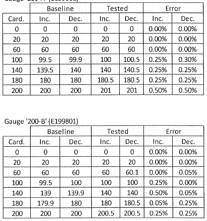
- EXAMPLE 1 A Evacuate/Fill a 4" isolation ring assembly (e.g., buna-N bladder material) with silicone oil. Evacuate/Fill a 200 psi process gauge with silicone oil. Assemble the gauge and isolation ring assembly together (not under pressure), and take readings (Table 1 ).
- FIG. 15 is a graph for Error versus Pressure for parts/components filled separately and assembled at 0 Pressure.
- Gauge '200-A' (E199802)
- Gauge '200-B' (E199801)
- FIG. 16 is a graph for Error versus Pressure for parts/components filled separately and assembled at Full Scale Pressure (100 psi).
- FIG. 17 is a graph showing aggregate error of instrument removal.
- Table 3 :
- the instrument Once the instrument has been assembled to the isolation ring, it can be removed/re- attached while under any suitable pressure (e.g., 300 psi MAX). The following test shows that this can be done while maintaining the stated accuracy.
- any suitable pressure e.g. 300 psi MAX.
- FIG. 18 is a graph showing gauge error after
- EXAMPLE 3B Same procedure as Example 3A, except with increasing pressure (Table 5).
- FIG. 19 is a graph showing gauge error after removal/attachment at varying increasing pressures.
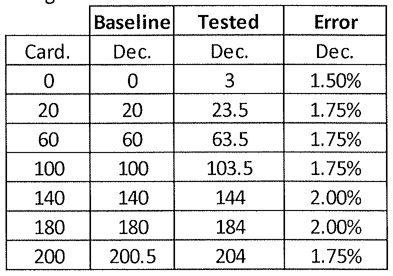
- FIG. 20 is a graph for Error versus Pressure for replacement instruments - swap at 0 psi.
- Gauge '200- ⁇ ' ( ⁇ 199802)
- Gauge '200- B' (E199801)
- FIG. 21 is a graph for Error versus Pressure for replacement instruments - pre- charged at 200 psi - swap at 200 psi.
- FIG. 22 is a graph for Error versus Pressure for replacement instruments - pre-charged at 0 psi - swap at 200 psi.
- FIG. 23 is a graph for Error versus Pressure for Gauge 'A' Error.
- FIG. 24 is a graph for Error versus Pressure for Gauge 'B' Error.
- FIG. 25 is a graph for Error versus Pressure for Gauge 'A' Error due to varying seal sizes.
- Evacuate/Fill a 4" isolation ring e.g., buna-N bladder material
- FIG. 26 is a graph for Error versus Pressure for Gauge Error due to varying size.
Landscapes
- Physics & Mathematics (AREA)
- General Physics & Mathematics (AREA)
- Fluid Mechanics (AREA)
- Measuring Fluid Pressure (AREA)
Abstract
Description




Claims
Priority Applications (6)
| Application Number | Priority Date | Filing Date | Title |
|---|---|---|---|
| JP2016560368A JP6284656B2 (en) | 2014-04-03 | 2015-04-02 | How to replace process measurement equipment |
| EP15772757.9A EP3126793B1 (en) | 2014-04-03 | 2015-04-02 | Method for replacing a process measurement instrument |
| SG11201607941PA SG11201607941PA (en) | 2014-04-03 | 2015-04-02 | Method for replacing a process measurement instrument |
| CN201580020576.7A CN106461447B (en) | 2014-04-03 | 2015-04-02 | Method for replacing process measuring instruments |
| CA2943853A CA2943853C (en) | 2014-04-03 | 2015-04-02 | Method for replacing a process measurement instrument |
| BR112016022921-5A BR112016022921B1 (en) | 2014-04-03 | 2015-04-02 | METHOD TO REPLACE A PROCESS MEASUREMENT INSTRUMENT |
Applications Claiming Priority (2)
| Application Number | Priority Date | Filing Date | Title |
|---|---|---|---|
| US14/244,372 | 2014-04-03 | ||
| US14/244,372 US9429490B2 (en) | 2014-04-03 | 2014-04-03 | Systems and related methods for installing or replacing a process measurement instrument |
Publications (1)
| Publication Number | Publication Date |
|---|---|
| WO2015153842A1 true WO2015153842A1 (en) | 2015-10-08 |
Family
ID=54209524
Family Applications (1)
| Application Number | Title | Priority Date | Filing Date |
|---|---|---|---|
| PCT/US2015/024008 Ceased WO2015153842A1 (en) | 2014-04-03 | 2015-04-02 | Method for replacing a process measurement instrument |
Country Status (8)
| Country | Link |
|---|---|
| US (1) | US9429490B2 (en) |
| EP (1) | EP3126793B1 (en) |
| JP (1) | JP6284656B2 (en) |
| CN (1) | CN106461447B (en) |
| BR (1) | BR112016022921B1 (en) |
| CA (1) | CA2943853C (en) |
| SG (1) | SG11201607941PA (en) |
| WO (1) | WO2015153842A1 (en) |
Families Citing this family (5)
| Publication number | Priority date | Publication date | Assignee | Title |
|---|---|---|---|---|
| DE102014005409A1 (en) * | 2014-04-10 | 2015-10-15 | Wika Alexander Wiegand Se & Co. Kg | Diaphragm seal with adapter |
| DE102018126230A1 (en) * | 2018-10-22 | 2020-04-23 | Truedyne Sensors AG | Method for verifying a density and / or viscosity measuring device in a measuring point |
| CA3142406A1 (en) * | 2020-12-18 | 2022-06-18 | Romet Limited | Multi-function t-fitting |
| DE102021133085A1 (en) | 2021-12-14 | 2022-02-17 | LABOM Meß- und Regeltechnik Gesellschaft mit beschränkter Haftung | Separable hydraulic system |
| JP7771718B2 (en) * | 2021-12-17 | 2025-11-18 | Smc株式会社 | Pressure Gauges and Fluid Pressure Systems |
Citations (7)
| Publication number | Priority date | Publication date | Assignee | Title |
|---|---|---|---|---|
| US4763527A (en) * | 1987-01-23 | 1988-08-16 | Red Valve Co., Inc. | Temperature-resistant isolation fluid pressure detector |
| US4884452A (en) * | 1988-08-31 | 1989-12-05 | Delaware Capital Formation, Inc. | Pressure monitoring device isolator |
| US5708210A (en) * | 1996-03-12 | 1998-01-13 | Gardellin; David | Pressure monitoring isolating device |
| US20020083977A1 (en) * | 2000-11-02 | 2002-07-04 | Bernhard Beck | Interchangeable fitting |
| US20060278003A1 (en) * | 2003-02-18 | 2006-12-14 | Dresser, Inc., A Delaware Corporation | Pressure measurement |
| US20130031984A1 (en) * | 2011-08-01 | 2013-02-07 | Honeywell International Inc. | Interchangeable pressure sensor assembly and methods of assembly |
| WO2014035243A1 (en) * | 2012-08-30 | 2014-03-06 | Nederlandse Organisatie Voor Toegepast-Natuurwetenschappelijk Onderzoek Tno | Pressure sensing assembly |
Family Cites Families (26)
| Publication number | Priority date | Publication date | Assignee | Title |
|---|---|---|---|---|
| US3163529A (en) | 1960-04-29 | 1964-12-29 | Nat Lead Co | Fluid pressure measuring element |
| US3563095A (en) | 1969-01-06 | 1971-02-16 | Dover Corp | Fluid pressure sensor |
| US3557620A (en) * | 1969-03-20 | 1971-01-26 | Nat Lead Co | Fluid pressure measuring means |
| US3645139A (en) | 1970-06-04 | 1972-02-29 | John R Z | Self-retaining diaphragm seal for recording instrument |
| US3797317A (en) | 1972-12-07 | 1974-03-19 | C Peterson | Split valve test plug |
| US4109535A (en) | 1974-11-25 | 1978-08-29 | Ametek, Inc. | Diaphragm seal for pressure sensing instrument |
| US4082002A (en) | 1977-03-07 | 1978-04-04 | Vetco, Inc. | Gauge flange |
| US4192192A (en) | 1978-11-02 | 1980-03-11 | General Signal Corporation | Diaphragm seal assembly |
| US4218926A (en) | 1979-01-25 | 1980-08-26 | Dover Corporation | Isolating pressure sensor |
| US4534224A (en) | 1984-05-17 | 1985-08-13 | Red Valve Company, Inc. | Isolation fluid pressure detector |
| US4598581A (en) | 1984-06-25 | 1986-07-08 | Fmc Corporation | Quick connect diagnostic system |
| US4577511A (en) | 1984-11-05 | 1986-03-25 | Wetzel Donald C | Air line pressure tester |
| US4840068A (en) | 1988-03-14 | 1989-06-20 | Mayhew Jr John D | Pipe pressure sensor |
| US5022271A (en) | 1989-12-12 | 1991-06-11 | Hannon Jr Dewey | Pressure sensing device for pipes |
| JPH03104838U (en) * | 1990-02-07 | 1991-10-30 | ||
| US5154083A (en) | 1991-02-14 | 1992-10-13 | Larad Equipment Corporation | Instrument insolator and method of making same |
| JP3079213B2 (en) * | 1991-12-25 | 2000-08-21 | 清原 まさ子 | Fluid equipment |
| JPH0875585A (en) | 1994-09-09 | 1996-03-22 | Smc Corp | Connection structure of pressure detector |
| US5711508A (en) | 1995-06-07 | 1998-01-27 | Itt Automotive, Inc. | Quick connect fluid coupling equipped with check valve and service valve |
| US5708201A (en) | 1996-05-24 | 1998-01-13 | Pierburg Instruments, Inc. | Fuel delivery measurement system with automatic pump matching |
| JP3871290B2 (en) * | 1998-02-27 | 2007-01-24 | 大阪瓦斯株式会社 | Gas piping airtightness / leakage inspection method and apparatus, and pressure measuring instrument |
| JP2001033334A (en) * | 1999-07-16 | 2001-02-09 | Osaka Gas Co Ltd | Gas pressure measuring instrument |
| US6520022B1 (en) | 2000-11-08 | 2003-02-18 | The Reliable Automatic Sprinkler Co., Inc. | Direct connect pressure tester arrangement |
| DE202004005451U1 (en) * | 2004-04-06 | 2004-06-24 | Bartec Gmbh | Device for exchanging a measuring probe during operation |
| US7258017B1 (en) | 2006-04-10 | 2007-08-21 | Rosemount Inc. | Industrial process pressure transmitter with field repairable remote seals |
| CN104215285A (en) * | 2014-08-28 | 2014-12-17 | 昆山超强光电设备有限公司 | Electromagnetic flow meter |
-
2014
- 2014-04-03 US US14/244,372 patent/US9429490B2/en active Active
-
2015
- 2015-04-02 WO PCT/US2015/024008 patent/WO2015153842A1/en not_active Ceased
- 2015-04-02 BR BR112016022921-5A patent/BR112016022921B1/en active IP Right Grant
- 2015-04-02 CN CN201580020576.7A patent/CN106461447B/en active Active
- 2015-04-02 SG SG11201607941PA patent/SG11201607941PA/en unknown
- 2015-04-02 JP JP2016560368A patent/JP6284656B2/en active Active
- 2015-04-02 CA CA2943853A patent/CA2943853C/en active Active
- 2015-04-02 EP EP15772757.9A patent/EP3126793B1/en active Active
Patent Citations (7)
| Publication number | Priority date | Publication date | Assignee | Title |
|---|---|---|---|---|
| US4763527A (en) * | 1987-01-23 | 1988-08-16 | Red Valve Co., Inc. | Temperature-resistant isolation fluid pressure detector |
| US4884452A (en) * | 1988-08-31 | 1989-12-05 | Delaware Capital Formation, Inc. | Pressure monitoring device isolator |
| US5708210A (en) * | 1996-03-12 | 1998-01-13 | Gardellin; David | Pressure monitoring isolating device |
| US20020083977A1 (en) * | 2000-11-02 | 2002-07-04 | Bernhard Beck | Interchangeable fitting |
| US20060278003A1 (en) * | 2003-02-18 | 2006-12-14 | Dresser, Inc., A Delaware Corporation | Pressure measurement |
| US20130031984A1 (en) * | 2011-08-01 | 2013-02-07 | Honeywell International Inc. | Interchangeable pressure sensor assembly and methods of assembly |
| WO2014035243A1 (en) * | 2012-08-30 | 2014-03-06 | Nederlandse Organisatie Voor Toegepast-Natuurwetenschappelijk Onderzoek Tno | Pressure sensing assembly |
Non-Patent Citations (1)
| Title |
|---|
| See also references of EP3126793A4 * |
Also Published As
| Publication number | Publication date |
|---|---|
| JP6284656B2 (en) | 2018-02-28 |
| JP2017509892A (en) | 2017-04-06 |
| BR112016022921A2 (en) | 2017-08-15 |
| CA2943853C (en) | 2022-05-31 |
| EP3126793A4 (en) | 2017-11-22 |
| US9429490B2 (en) | 2016-08-30 |
| CA2943853A1 (en) | 2015-10-08 |
| EP3126793A1 (en) | 2017-02-08 |
| EP3126793B1 (en) | 2019-12-25 |
| CN106461447B (en) | 2019-08-30 |
| SG11201607941PA (en) | 2016-10-28 |
| BR112016022921B1 (en) | 2022-03-08 |
| CN106461447A (en) | 2017-02-22 |
| US20150285700A1 (en) | 2015-10-08 |
Similar Documents
| Publication | Publication Date | Title |
|---|---|---|
| CA2943853C (en) | Method for replacing a process measurement instrument | |
| US4192192A (en) | Diaphragm seal assembly | |
| CN103842789B (en) | Retrievable pressure transducer | |
| US9389106B2 (en) | Remote seal pressure measurement system for subsea use | |
| CN104048125B (en) | Redundant seal on-line checking pipe joint | |
| US6981513B2 (en) | Fluid flow management system | |
| US9964222B1 (en) | Failsafe hose | |
| US11326978B2 (en) | Leak indicating clamp | |
| US3102427A (en) | Pressure gauge connector | |
| HK1228995A1 (en) | Method for replacing a process measurement instrument | |
| CN108883351B (en) | filter with pressure indicator | |
| US20190234822A1 (en) | Hot-swappable access/retrieval plug for high pressure fluid systems | |
| US20220112698A1 (en) | A testing device for backflow prevention devices | |
| RU120221U1 (en) | MEMBRANE PRESSURE SENSOR - DDM | |
| AU2007100534A4 (en) | Improved dry manometer | |
| CN204253016U (en) | Overpressure protection device | |
| JP2013127430A (en) | Leakage testing machine for pipeline | |
| JPH01169335A (en) | Probe for tank airtightness tester | |
| DE20202760U1 (en) | Seal for leak-testing hydraulic elevator pit, has disc that serves as fixing point to attach to wall of elevator pit, with foaming material inserted and hardened | |
| GB2412746A (en) | Pressure testing apparatus | |
| NO20161920A1 (en) | A hose arrangement and a method for testing the integrity of a hose unit of a hose arrangement | |
| Pumps | Pressure measurement solution |
Legal Events
| Date | Code | Title | Description |
|---|---|---|---|
| 121 | Ep: the epo has been informed by wipo that ep was designated in this application |
Ref document number: 15772757 Country of ref document: EP Kind code of ref document: A1 |
|
| ENP | Entry into the national phase |
Ref document number: 2943853 Country of ref document: CA |
|
| ENP | Entry into the national phase |
Ref document number: 2016560368 Country of ref document: JP Kind code of ref document: A |
|
| NENP | Non-entry into the national phase |
Ref country code: DE |
|
| REEP | Request for entry into the european phase |
Ref document number: 2015772757 Country of ref document: EP |
|
| WWE | Wipo information: entry into national phase |
Ref document number: 2015772757 Country of ref document: EP |
|
| REG | Reference to national code |
Ref country code: BR Ref legal event code: B01A Ref document number: 112016022921 Country of ref document: BR |
|
| ENP | Entry into the national phase |
Ref document number: 112016022921 Country of ref document: BR Kind code of ref document: A2 Effective date: 20160930 |