WO2015156031A1 - 通信端末および無線センサネットワークシステム - Google Patents
通信端末および無線センサネットワークシステム Download PDFInfo
- Publication number
- WO2015156031A1 WO2015156031A1 PCT/JP2015/054233 JP2015054233W WO2015156031A1 WO 2015156031 A1 WO2015156031 A1 WO 2015156031A1 JP 2015054233 W JP2015054233 W JP 2015054233W WO 2015156031 A1 WO2015156031 A1 WO 2015156031A1
- Authority
- WO
- WIPO (PCT)
- Prior art keywords
- sensor
- sensor node
- host
- wireless
- communication terminal
- Prior art date
- Legal status (The legal status is an assumption and is not a legal conclusion. Google has not performed a legal analysis and makes no representation as to the accuracy of the status listed.)
- Ceased
Links
Images




Classifications
-
- H—ELECTRICITY
- H04—ELECTRIC COMMUNICATION TECHNIQUE
- H04Q—SELECTING
- H04Q9/00—Arrangements in telecontrol or telemetry systems for selectively calling a substation from a main station, in which substation desired apparatus is selected for applying a control signal thereto or for obtaining measured values therefrom
-
- H—ELECTRICITY
- H04—ELECTRIC COMMUNICATION TECHNIQUE
- H04W—WIRELESS COMMUNICATION NETWORKS
- H04W24/00—Supervisory, monitoring or testing arrangements
- H04W24/08—Testing, supervising or monitoring using real traffic
-
- H—ELECTRICITY
- H04—ELECTRIC COMMUNICATION TECHNIQUE
- H04W—WIRELESS COMMUNICATION NETWORKS
- H04W4/00—Services specially adapted for wireless communication networks; Facilities therefor
- H04W4/20—Services signaling; Auxiliary data signalling, i.e. transmitting data via a non-traffic channel
-
- H—ELECTRICITY
- H04—ELECTRIC COMMUNICATION TECHNIQUE
- H04W—WIRELESS COMMUNICATION NETWORKS
- H04W52/00—Power management, e.g. Transmission Power Control [TPC] or power classes
- H04W52/02—Power saving arrangements
- H04W52/0209—Power saving arrangements in terminal devices
- H04W52/0212—Power saving arrangements in terminal devices managed by the network, e.g. network or access point is leader and terminal is follower
- H04W52/0216—Power saving arrangements in terminal devices managed by the network, e.g. network or access point is leader and terminal is follower using a pre-established activity schedule, e.g. traffic indication frame
-
- H—ELECTRICITY
- H04—ELECTRIC COMMUNICATION TECHNIQUE
- H04W—WIRELESS COMMUNICATION NETWORKS
- H04W52/00—Power management, e.g. Transmission Power Control [TPC] or power classes
- H04W52/02—Power saving arrangements
- H04W52/0209—Power saving arrangements in terminal devices
- H04W52/0212—Power saving arrangements in terminal devices managed by the network, e.g. network or access point is leader and terminal is follower
- H04W52/0219—Power saving arrangements in terminal devices managed by the network, e.g. network or access point is leader and terminal is follower where the power saving management affects multiple terminals
-
- H—ELECTRICITY
- H04—ELECTRIC COMMUNICATION TECHNIQUE
- H04W—WIRELESS COMMUNICATION NETWORKS
- H04W52/00—Power management, e.g. Transmission Power Control [TPC] or power classes
- H04W52/02—Power saving arrangements
- H04W52/0209—Power saving arrangements in terminal devices
- H04W52/0261—Power saving arrangements in terminal devices managing power supply demand, e.g. depending on battery level
- H04W52/0274—Power saving arrangements in terminal devices managing power supply demand, e.g. depending on battery level by switching on or off the equipment or parts thereof
-
- H—ELECTRICITY
- H04—ELECTRIC COMMUNICATION TECHNIQUE
- H04Q—SELECTING
- H04Q2209/00—Arrangements in telecontrol or telemetry systems
- H04Q2209/40—Arrangements in telecontrol or telemetry systems using a wireless architecture
-
- H—ELECTRICITY
- H04—ELECTRIC COMMUNICATION TECHNIQUE
- H04Q—SELECTING
- H04Q2209/00—Arrangements in telecontrol or telemetry systems
- H04Q2209/80—Arrangements in the sub-station, i.e. sensing device
- H04Q2209/84—Measuring functions
- H04Q2209/845—Measuring functions where the measuring is synchronized between sensing devices
-
- H—ELECTRICITY
- H04—ELECTRIC COMMUNICATION TECHNIQUE
- H04W—WIRELESS COMMUNICATION NETWORKS
- H04W84/00—Network topologies
- H04W84/18—Self-organising networks, e.g. ad-hoc networks or sensor networks
-
- Y—GENERAL TAGGING OF NEW TECHNOLOGICAL DEVELOPMENTS; GENERAL TAGGING OF CROSS-SECTIONAL TECHNOLOGIES SPANNING OVER SEVERAL SECTIONS OF THE IPC; TECHNICAL SUBJECTS COVERED BY FORMER USPC CROSS-REFERENCE ART COLLECTIONS [XRACs] AND DIGESTS
- Y02—TECHNOLOGIES OR APPLICATIONS FOR MITIGATION OR ADAPTATION AGAINST CLIMATE CHANGE
- Y02D—CLIMATE CHANGE MITIGATION TECHNOLOGIES IN INFORMATION AND COMMUNICATION TECHNOLOGIES [ICT], I.E. INFORMATION AND COMMUNICATION TECHNOLOGIES AIMING AT THE REDUCTION OF THEIR OWN ENERGY USE
- Y02D30/00—Reducing energy consumption in communication networks
- Y02D30/70—Reducing energy consumption in communication networks in wireless communication networks
Definitions
- the present invention relates to a communication terminal and a wireless sensor network system, and more particularly to a communication terminal capable of power saving communication and a wireless sensor network system to which the communication terminal can be applied.
- a wireless sensor network system is disclosed (for example, see Patent Document 1).
- a plurality of sensor nodes always turn on receivers in a plurality of sensor nodes in order to maintain a state in which signals from a host can always be received even after transmission of wireless transmission data is completed. It is necessary to keep.
- the reception circuit is always turned on to be in a reception standby state. I had to do it. For this reason, power consumption is relatively large.
- An object of the present invention is to provide a communication terminal capable of power saving communication and a wireless sensor network system to which this communication terminal can be applied.
- a sensor that can collect sensor information at a self-supporting timing, a control unit that is connected to the sensor and can process the sensor information, and is connected to the control unit Connected to the memory, a wireless transmission / reception unit connected to the control unit, an antenna connected to the wireless transmission / reception unit and capable of wireless transmission of the sensor information or a result of arithmetic processing of the sensor information, and connected to the control unit
- Sensor node communication terminal comprising a power supply unit configured to be connected to the control unit and capable of receiving the second wireless transmission data from the host side for a predetermined period after the transmission of the first wireless transmission data is completed.
- a control unit a memory connected to the control unit, a radio transmission / reception unit connected to the control unit, and an antenna connected to the radio transmission / reception unit
- a host communication terminal collects sensing data from the sensor nodes via wireless communication and designates a change in communication speed for a plurality of sensor nodes in accordance with the received electric field strength of the received radio waves.
- the apparatus includes a plurality of sensor nodes and a host capable of receiving the first wireless transmission data from the plurality of sensor nodes constantly or periodically.
- a wireless sensor network system is provided, wherein the second wireless transmission data from the host side can be received for a predetermined period after transmission of wireless transmission data is completed.
- a sensor that can collect sensor information at a self-supporting timing, a control unit that is connected to the sensor and can process the sensor information, and the control unit A connected memory; a wireless transmission unit connected to the control unit; an antenna connected to the wireless transmission unit and capable of performing wireless transmission of the sensor information or a result of arithmetic processing of the sensor information; and the control unit A wireless sensor network comprising a plurality of sensor nodes including a connected power supply unit, a timer connected to the control unit, and a host capable of receiving wireless transmission data from the plurality of sensor nodes constantly or periodically A system is provided.
- the present invention it is possible to provide a communication terminal capable of power saving communication and a wireless sensor network system to which this communication terminal can be applied.
- FIG. 1 is a schematic configuration diagram of a wireless sensor network system to which a communication terminal according to a first embodiment can be applied.
- FIG. 4 is a schematic timing chart for explaining a sleep time Ts between transmission data in a sensor node functioning as a communication terminal according to the first embodiment.
- a schematic timing chart of a data signal in the sensor node Pi In the wireless sensor network system to which the communication terminal according to the first embodiment can be applied, (a) a schematic timing chart of a data signal in the sensor node Pi, (b) in the host H corresponding to FIG. The typical timing chart figure of a data signal.
- an operation flowchart of wireless communication between the sensor node Pi and the host H (the absence of the flag FLG and transmission from the sensor node side to the host) A type in which a reception window time is always provided after.
- an operation flowchart of wireless communication between the sensor node Pi and the host H (after the flag FLG is defined and transmitted from the sensor node side to the host) Next, whether or not the reception window time is provided is notified by the value indicated by the flag FLG included in the transmission).
- the sensor block communication terminal which concerns on 2nd Embodiment Comprising: The typical block block diagram of the sensor node provided with a photovoltaic device. The typical bird's-eye view block diagram of the timer clock using the optical sensor applicable to the sensor node communication terminal which concerns on 2nd Embodiment.
- the sensor node communication terminal is a pattern diagram showing the relationship between the power generation amount P O and time t (day) of the photovoltaic device.
- a wireless sensor network system to which a communication terminal according to a comparative example can be applied, (a) a schematic timing chart of a data signal at the sensor node P1, (b) a schematic timing chart of a data signal at the sensor node P2, (c) ) A schematic timing chart of a data signal in the sensor node Pn.
- FIG. 4C is a schematic timing chart of a data signal in the sensor node Pn.
- FIG. 4B is a schematic diagram showing the relationship between the communication speed D (kbps) and the reception sensitivity S (dBm) between the host H and the sensor node Pi.
- A Schematic block configuration diagram of a host capable of wireless communication with a communication terminal according to the fourth embodiment
- B Schematic block configuration diagram of a sensor node functioning as a communication terminal according to the fourth embodiment.
- the communication terminal which concerns on the modification of 4th Embodiment, Comprising: The typical block block diagram of the sensor node provided with a photovoltaic device.
- a wireless sensor network system 100 to which a communication terminal (sensor node) 20 according to the first embodiment is applicable includes a plurality of sensor nodes 20 (P 1 , P 2 ,..., P i , P i + 1 ,..., P n ) and a host 10 that can receive the first wireless transmission data from the plurality of sensor nodes 20 constantly or periodically.
- the reception frequency in the host 10 is more frequent than the transmission frequency of the sensor node 20.
- the host 10 is a base station, and may be disposed on a support column 15 having a predetermined height, for example.
- the plurality of sensor nodes 20 can receive the second wireless transmission data from the host 10 side only for a predetermined short period after the transmission of the first wireless transmission data.
- the first wireless transmission data is sent from the plurality of sensor nodes 20 (P 1 , P 2 ,..., P i , P i + 1 ,..., P n ) to the host 10 at a predetermined timing. Sent.
- the second wireless transmission data is transmitted from the host 10 side to the plurality of sensor nodes 20 (P 1 , P 2 ,..., P i , P i only for a predetermined short period after the transmission of the first wireless transmission data. +1 ,..., P n ).
- the wireless sensor network system 100 to which the communication terminal 20 according to the first embodiment can be applied includes a plurality of sensor nodes 20 (P 1 , P 2 ,..., P i , P i + 1 ,. ), It is possible to receive the transmission data from the host 10 only for a predetermined short period after the transmission of the wireless transmission data, thereby reducing the power consumption.
- a plurality of sensor nodes 20 (P 1, P 2, ⁇ , P i, P i + 1, ..., P n) in, compared with the case where a state capable of receiving constantly wirelessly transmits data after end of transmission
- it is not necessary to always turn on the receivers in the plurality of sensor nodes 20 (P 1 , P 2 ,..., P i , P i + 1 ,..., P n ).
- the information collected in the host 10 is supplied to the cloud computing system using the Internet line or the like, and can be integratedly managed.
- the plurality of sensor nodes 20 are sensor information at independent timing, as will be described later in the description of FIG.
- Sensor 21 that can be collected at the place where the sensor is installed, a memory 22 connected to the sensor 21, a control unit 24 that is connected to the memory 22 and can process sensor information, and a wireless transmission / reception connected to the control unit 24 Unit (RF) 26, connected to the wireless transmission / reception unit 26, the antenna 28 capable of wirelessly transmitting sensor information or the result of calculating sensor information, the power supply unit 32 connected to the control unit 24, and the control unit 24 And a connected timer 30.
- RF control unit
- the memory 22 stores the sensor information acquired by the sensor 21.
- the sensor information acquired by the sensor 21 includes, for example, light, temperature, humidity, pressure, vibration, strain, inclination, switch information, depending on the application of the wireless sensor network system 100 to which the communication terminal (sensor node) 20 is applied. Etc. are included.
- an energy harvesting device such as a solar panel is mainly used.
- it can be applied to a structure in which this is replaced with a battery or provided in a hybrid. This is because the purpose of extending the life of the battery is the same.
- wireless sensor network system for bridges As a wireless sensor network system to which the communication terminal (sensor node) 20 according to the first embodiment can be applied, a schematic bird's-eye view configuration of the wireless sensor network system 300 for bridges is expressed as shown in FIG.
- the bridge wireless sensor network system 300 to which the communication terminal (sensor node) 20 according to the first embodiment can be applied includes a plurality of sensor nodes 20 11 , 20 12 ,..., 20 21 , as shown in FIG. 20 22, ..., 20 31, 20 32, ..., 20 41, 20 42, ... and a plurality of sensor nodes 20 11, 20 12, ..., 20 21, 20 22, ..., 20 31, 20 32, ..., , 20 42 ,... Are provided with hosts 10 1 , 10 2 , 10 3, and 10 4 that can receive the first wireless transmission data from 20 41 , 20 42 ,.
- the reception frequency in the host 10 is more frequent than the transmission frequency of the sensor node 20.
- the hosts 10 1 , 10 2 , 10 3, and 10 4 may be disposed at a connection portion between the columns 301, 302, 303, and 304 having a predetermined height and the road (or railroad track) 305.
- a plurality of wires 306 are connected between the columns 301, 302, 303, and 304 and the road (or railroad track) 305, and the road (or railroad track) 305 is connected by the columns 301, 302, 303, and 304. Is supporting.
- a plurality of sensor nodes 20 11 , 20 12 ,..., 20 21 , 20 22 ,..., 20 31 , 20 32 ,..., 20 41 , 20 42 , etc. are composed of a plurality of wires 306 and a road (or railroad track) 305. It may be arranged in the connection part.
- a plurality of sensor nodes 20 11, 20 12, ..., only a predetermined short period after the transmission ends the first radio transmission data is capable of receiving a second radio transmission data from the host 10 1 side.
- the first wireless transmission data is transmitted from the plurality of sensor nodes 20 11 , 20 12 ,... To the host 10 1 at a predetermined timing.
- the communication terminal 20 for bridges wireless sensor network system 300 can be applied to according to the first embodiment, a plurality of sensor nodes 20 11, 20 12, ..., 20 21, 20 22, ..., 20 31, 20 32, ... - 20 41, 20 42, in ..., only a predetermined short period after the transmission end radio transmission data, by which a state capable of receiving the transmission data from the host 10 1, 10 2, 10 3, 10 4 side Low power consumption. That is, since it is not necessary to always turn on the receivers in the plurality of sensor nodes, the power consumption is reduced.
- Information collected in the hosts 10 1 , 10 2 , 10 3, and 10 4 is supplied to a cloud computing system using an Internet line or the like, and can be integratedly managed.
- the sensor 21 that can collect sensor information at a self-supporting location
- the control unit 24 that is connected to the sensor 21 and can process the sensor information
- the memory 22 that is connected to the control unit 24
- a wireless transmission / reception unit (RF) 26 connected to the control unit 24, an antenna 28 connected to the wireless transmission / reception unit 26, and capable of wirelessly transmitting sensor information or a result obtained by processing the sensor information; and a control unit 24.
- a power supply unit 32 and a timer 30 connected to the control unit 24.
- sensor information acquired by the sensor 21 is stored in the memory 22.
- the sensor information includes, for example, light, temperature, humidity, pressure, vibration, distortion, inclination, tension, and the like.
- the power source unit 32 for example, an energy harvesting device such as a solar panel is mainly used. On the other hand, it can be applied to a structure in which this is replaced with a battery or provided in a hybrid.
- wireless transmission / reception may be performed by selecting one of the hosts arranged on both sides. Further, as will be described later in the third embodiment, a method for avoiding data collision may be applied.
- Wireless sensor network system 200 for farms As a wireless sensor network system to which the communication terminal (sensor node) 20 according to the first embodiment can be applied, a schematic bird's-eye view configuration of the farm wireless sensor network system 200 is expressed as shown in FIG.
- Wireless sensor network system 200 for farms as shown in FIG. 3, may be composed of a plurality of small wireless sensor for farm network system 200 1 ⁇ 200 2 ⁇ ... ⁇ 200 m.
- the plurality of small-scale farm wireless sensor network systems 200 1 , 200 2 ,..., 200 m may be divided, for example, in units of cultivated crops.
- the farm wireless sensor network system 200 to which the communication terminal (sensor node) 20 according to the first embodiment can be applied includes a plurality of sensor nodes 20 11 , 20 12 ,. 20 21 ⁇ 20 22 ⁇ ... ⁇ 20 2n, ⁇ , 20 and m1 ⁇ 20 m2 ⁇ ... ⁇ 20 mn, a plurality of sensor nodes 20 11 ⁇ 20 12 ⁇ ... ⁇ 20 1n, 20 21 ⁇ 20 22 ⁇ ... ⁇ 20 comprises 2n, ⁇ ⁇ ⁇ , a 20 m1 ⁇ 20 m2 ⁇ ... ⁇ 20 the first radio transmission data from the mn constantly or periodically receivable plurality of hosts 10 1 ⁇ 10 2 ⁇ ... ⁇ 10 m.
- the reception frequency in the host 10 is more frequent than the transmission frequency of the sensor node 20.
- the plurality of sensor nodes 20 11 ⁇ 20 12 ⁇ ... ⁇ 20 1n for example, be radio transmitted between the host 10 1, Similarly, the plurality of sensor nodes 20 21 ⁇ 20 22 ⁇ ... ⁇ 20 2n, a possible radio transceiver with the host 10 2, ..., a plurality of sensor nodes 20 m1 ⁇ 20 m2 ⁇ ... ⁇ 20 mn can be wirelessly transmitted and received between the host 10 m.
- a plurality of sensor nodes 20 11 ⁇ 20 12 ⁇ ... ⁇ 20 1n only a predetermined short period after the transmission ends the first radio transmission data is capable of receiving a second radio transmission data from the host 10 1 side.
- the first wireless transmission data from a plurality of sensor nodes 20 11 ⁇ 20 12 ⁇ ... ⁇ 20 1n, at a predetermined timing and sent to the host 10 1.
- the second radio transmission data is transmitted to the first radio transmission data for a predetermined short period after the transmission end, to a plurality of sensor nodes 20 11 ⁇ 20 12 ⁇ ... ⁇ 20 1n the host 10 1 side .
- Information collected in the hosts 10 1 , 10 2 , 10 3 ,..., 10 m is supplied to a cloud computing system using an Internet line or the like and can be integratedly managed.
- the farm wireless sensor network system 200 to which the communication terminal 20 according to the first embodiment can be applied includes a plurality of sensor nodes 20 11 , 20 12 ,..., 20 1n , 20 21 , 20 22 ,. ..., the state in 20 m1 ⁇ 20 m2 ⁇ ... ⁇ 20 mn, which can receive the transmission data of the radio transmission data for a predetermined short period after transmission completion from the host 10 1 ⁇ 10 2 ⁇ ... ⁇ 10 m side
- power consumption is reduced. That is, since it is not necessary to always turn on the receivers in the plurality of sensor nodes, the power consumption is reduced.
- a sensor 21 that can collect sensor information at a self-supporting location, a control unit 24 that is connected to the sensor 21 and that can process the sensor information, and a memory that is connected to the control unit 24 22, a wireless transmission / reception unit (RF) 26 connected to the control unit 24, an antenna 28 connected to the wireless transmission / reception unit 26 and capable of wirelessly transmitting sensor information or a result of processing sensor information, and a control unit 24
- the power supply part 32 connected and the timer 30 connected to the control part 24 are provided.
- sensor information acquired by the sensor 21 is stored in the memory 22.
- the sensor information includes, for example, light, temperature, humidity, atmospheric pressure, vibration, distortion, inclination, switch information, and the like at a place where the farm is installed.
- the power source unit 32 for example, an energy harvesting device such as a solar panel is mainly used. On the other hand, it can be applied to a structure in which this is replaced with a battery or provided in a hybrid.
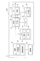
- the schematic block configuration of the host 10 (H) capable of wireless communication with the sensor node communication terminal according to the first embodiment includes a memory 12 and a control connected to the memory 12 as shown in FIG. Unit 14, a radio transmission / reception unit (RF) 16 connected to control unit 14, and an antenna 18 connected to radio transmission / reception unit (RF) 16.
- the memory 12 stores control information necessary for wireless communication between the host 10 and the sensor node 20.
- the control unit 14 executes wireless communication control between the host 10 and the sensor node 20 based on the control information stored in the memory 12.
- the wireless transmission / reception unit (RF) 16 transmits / receives wireless data between the host 10 and the sensor node 20 via the antenna 18.
- the host 10 (H) is a base station, and it is not necessary to provide a power supply unit. Therefore, although not shown in FIG. 4A, power is acquired from various energy sources depending on the application. You may provide the power supply part structure (energy harvesting).
- the host 10 (H) can receive the first wireless transmission data from the sensor node 20 (P) constantly or periodically. Here, when receiving periodically, the reception frequency in a host is more frequent than the transmission frequency of a sensor node.
- the schematic block configuration of the sensor node 20 (P) functioning as the communication terminal according to the first embodiment is a place where sensor information is installed at an independent timing, as shown in FIG.
- RF wireless transmission / reception unit
- an antenna 28 that is connected to the wireless transmission / reception unit 26 and can wirelessly transmit sensor information or a result obtained by processing the sensor information, a power supply unit 32 connected to the control unit 24, and a timer 30 connected to the control unit 24.
- the sensor node 20 (P) can receive the transmission data from the host 10 only for a predetermined short period after the transmission of the wireless transmission data.
- the sensor node 20 (P) functioning as the communication terminal according to the first embodiment is in a state where it can receive transmission data from the host 10 side for a predetermined short period after transmission of wireless transmission data is completed. Low power consumption. That is, since it is not necessary to always turn on the receiver in the sensor node 20 (P), the power consumption is reduced.
- the sensor information includes, for example, light, temperature, humidity, pressure, vibration, distortion, tilt, switch information, noise level, and the like. That is, the sensor 21 can be a sensor that can measure various environmental factors such as a temperature sensor, a humidity sensor, a pressure sensor, a vibration sensor, a strain sensor, a tilt sensor, and a switch information sensor.
- the memory 22 stores sensor information acquired by the sensor 21.
- the memory 12 also stores control information necessary for wireless communication between the host 10 and the sensor node 20.
- the control unit 24 executes wireless communication control between the host 10 and the sensor node 20 based on the sensor information / control information stored in the memory 12. Moreover, the control part 24 can process sensor information.
- a timer 30 is connected to the control unit 24, and timing control and time setting of the sensor node 20 (P) are possible.
- the power supply unit 32 connected to the control unit 24 is supplied with power from various energy sources according to applications such as solar energy, vibration energy of the surrounding environment, wind energy, energy obtained from the thermoelectric generator due to temperature fluctuation, and switch opening / closing. (Energy harvesting) is possible.
- the power supply unit 32 connected to the control unit 24 desirably does not require battery replacement.
- an energy harvesting device such as a solar panel is mainly used.
- it can be applied to a structure in which this is replaced with a battery or provided in a hybrid. This is because the purpose of extending the life of the battery is the same.
- the sensor node 20 (P) functioning as the communication terminal according to the first embodiment is connected to the host 10 (H) in the time width T1 between the timer time t1 and the timer time t2, as shown in FIG. after transmitting the transmission data T X, the time width T2 between timer times t3 and timer time t4 after lapse of a relatively long sleep time Ts, it is possible to transmit the transmission data T X to the host 10 (H).
- the sensor node 20 (P) is capable of intermittent sensing operation, after transmitting the transmission data T X to the host 10 (H), at all times, and the receiver in the sensor node 20 (P) to the on state
- the transmission data T X can be transmitted to the host 10 (H) only in a slight time width T2 after the elapse of the sleep time Ts. For this reason, a power saving operation is possible.
- FIG. 6A a schematic timing chart of the data signal in the sensor node Pi is expressed as shown in FIG. 6A
- FIG. A schematic timing chart of a data signal in the host H corresponding to is expressed as shown in FIG.
- the flag FLG is defined in the wireless communication operation between the sensor node Pi and the host H after the transmission from the sensor node side to the host as shown in the flowchart of FIG. Whether or not the reception window time is subsequently provided corresponds to the type that is notified in advance by the value indicated by the flag FLG included in the transmission.
- FIG. 6A there is an operation mode without FLG.
- the flag FLG is present in the operation of wireless communication between the sensor node Pi and the host H. And a type in which a reception window time is always provided after transmission from the sensor node side to the host).
- the detailed timing chart of the data signal in the sensor node Pi is expressed as shown in FIG. 7A, and the detailed timing chart of the data signal in the host H corresponding to FIG. 7A is shown in FIG. It is expressed as shown in b).
- the transmission / reception patterns include the following seven operation modes (A) to (G) depending on whether the sensor node has a reception window time and a flag in transmission data.
- the flag FLG When the flag FLG is not equipped, the following (A), (D), and (E) modes are selected.
- the flag FLG is equipped, the following (B), (C), (F), and (G) modes are set. It becomes. Details will be described later with reference to FIG.
- the sensor node Pi sets a reception waiting period after transmitting wireless transmission data, but does not receive from the host H.
- the sensor node Pi sets a reception waiting period after transmitting wireless transmission data, and is in a mode of receiving from the host H (control signal only).
- the sensor node Pi After transmitting wireless transmission data, the sensor node Pi sets a reception waiting period, receives from the host H (only data request signal), and then transmits data.
- the sensor node Pi sets a reception waiting period after transmitting wireless transmission data, but does not receive from the host H.
- the sensor node Pi sets a reception waiting period after transmitting wireless transmission data, and is in a mode of receiving from the host H (control signal only).
- (G) A mode in which the sensor node Pi transmits a wireless transmission data, sets a reception standby period, receives from the host H (only a data request signal), and then transmits data.
- (A) A mode in which the sensor node Pi provides a reception waiting period R Xi3 after transmission of the first wireless transmission data T Xi3 , but the host H does not transmit the second wireless transmission data T Xh to the sensor node Pi.
- the sensor node Pi After transmitting the first wireless transmission data T Xi3 , the sensor node Pi provides a reception waiting period R Xi3 , and the host H transmits the second wireless transmission data T Xh to the sensor node Pi. In this mode, the sensor node Pi then transmits the third wireless transmission data T Xi4 to the host H.
- the amount of data / number of transmissions is specified by the contents of the data request signal.
- the flag FLG is included in the data currently being transmitted, and indicates whether or not a window time for reception is provided on the sensor node Pi side during a predetermined period after this transmission.
- the second wireless transmission data T Xh is transmitted during the reception waiting period R Xi3 .
- the host side does not send anything during the reception waiting period R Xi3 .
- the case without the time R XI3 standby reception following the first radio transmission data T XI3 as the flag FLG 0 in the first radio transmission data T XI3, the currently received sensor node Pi to the host H side Indicates not to do.
- the sensor node side receives the received control. Operates according to the signal. That is, for example, the time information of the host H is received and synchronized with the clock in the sensor node.
- the flag FLG can be omitted in the case of a system in which the reception window time is always provided after the first wireless transmission data T Xi3 .
- the reception window time is always provided after the first wireless transmission data T Xi3 .
- the first wireless transmission data T Xi3 is transmitted from the sensor node 20 (P i ) to the host 10 (H) at a predetermined timing.
- the second wireless transmission data T Xh is transmitted from the host 10 (H) side to the sensor node 20 (P i ) within a predetermined short period after the transmission of the first wireless transmission data T Xi3. .
- a combination of a plurality of elements such as a determination element for determining whether or not the sensor node 20 (P i ) continues to wait for reception, for example, once every five days, only at midnight at night, etc. In some cases, it may be judged.
- At least one of the determination elements for determining whether or not the sensor node 20 (P i ) continues to wait for reception may be time or information according to time.
- At least one of the determination elements for determining whether or not the sensor node 20 (P i ) continues to wait for reception may be information regarding the number of times. For example, it is possible to open the reception window only once every 5 times or open the reception window only once a day depending on the application. Thus, the reception window R xi2 , R xi3, etc. may not be opened every time depending on the flag FLG indicating whether or not the sensor node 20 (P i ) will continue to wait for reception.
- a determination criterion that is determined in advance by combining information collected by at least one of the determination elements for determining whether or not the sensor node 20 (P i ) continues to wait for reception together with information collected so far. It may be information regarding the match determination result.
- the sensor node turns on the reception circuit “every time” for a short time after transmission.
- the host side always knows the transmission timing to the sensor node, and if the transmission is performed at that time, the sensor node can receive.
- the wireless sensor network system to which the communication terminal according to the first embodiment can be applied, it is not always necessary to turn on the receiving circuit of the sensor node, and only a limited time is required. Less power consumption. On the other hand, the timing that can be transmitted from the host side is limited, but such a delay is acceptable.
- the wireless sensor network system to which the communication terminal according to the first embodiment can be applied, whether or not the sensor node turns on the reception circuit for a short time after transmission is set as the immediately preceding transmission signal. It is indicated by the included flag FLG information, and the receiving circuit is turned on for a short time only after “Yes”. That is, since the power is not turned on every time, the power consumption is further reduced. On the other hand, the timing at which transmission from the host side can be further limited, but the interval at which the reception window opens is usually widened.
- an operation flowchart of wireless communication between the sensor node Pi and the host H (the absence of the flag FLG and transmission from the sensor node side to the host) 8 is a type in which a reception window time is always provided after), as shown in FIG.
- an operation flowchart of wireless communication between the sensor node Pi and the host H (a flag FLG is defined and transmitted from the sensor node side to the host) 9 is a type in which whether or not to provide a reception window time subsequent to the value indicated by the flag FLG included in the transmission) is expressed as shown in FIG.
- the wireless sensor network system to which the communication terminal according to the first embodiment can be applied, there is no flag FLG, and a reception window time is always provided after transmission from the sensor node side to the host (FIG. 8).
- the flag FLG is defined and whether or not a reception window time is subsequently provided after transmission from the sensor node to the host is notified by a value indicated by the flag FLG included in the transmission.
- There are two types (corresponding to the operation flowchart of FIG. 9).
- the type in which the reception window time is always provided after the transmission from the sensor node side to the host without the presence of the flag FLG has a period in which the reception circuit is turned on even if it is a little at every transmission on the sensor node side. In addition, it is only necessary to turn on the receiving circuit instead of every time (for example, once every 10 times, once a day, once every 5 times when the stored energy is higher than a predetermined level). Received).
- the type in which the flag FLG is defined and which is notified in advance by the value indicated by the flag FLG included in the transmission indicates whether or not the reception window time is provided after the transmission from the sensor node to the host is consumed. There is a feature that can reduce power.
- step S1 of FIG. 8 the sensor node transmits data to the host.
- step S2 the sensor node opens the reception window for a short time.
- step S3 the host receives the transmitted data.
- step S4 is there a transmission from the host to the sensor node? Judging.
- step S4 the process proceeds to step S12, and the host enters the next standby state.
- step S13 the process proceeds to step S13, where the sensor node closes the reception window and enters the sleep mode. (The sensor node counts the timer until the next time.)
- step S5 the process will transfer to step S5 and a host will transmit a control signal to a sensor node.
- step S6 the sensor node receives a control signal.
- step S7 the sensor node closes the reception window and executes control.
- step S8 the sensor node enters the sleep mode. (The sensor node counts the timer until the next time.) (K) If YES in step S4, the process proceeds to step S9, and the host transmits a data request signal to the sensor node.
- step S10 the sensor node receives a data request signal.
- step S11 the sensor node closes the reception window, and then returns to step S1, where the sensor node transmits data to the host.
- step S21 of FIG. 9 the sensor node transmits data to the host.
- step S22 is the flag FLG in the transmission data 1 or not? Judging.
- step S25 the host receives the transmitted data.
- step S26 is the flag FLG in the received data 1 or not? Judging.
- step S28 the process proceeds to step S29, and the host transmits a control signal to the sensor node.
- step S30 the sensor node receives a control signal.
- step S31 the sensor node closes the reception window and executes control.
- step S32 the sensor node enters the sleep mode. (The sensor node counts the timer until the next time.) (M) Alternatively, if YES in step S28, the host may move to step S33, and the host may transmit a data request signal to the sensor node.
- step S34 the sensor node receives the data request signal.
- step S35 the sensor node closes the reception window.
- step S21 the process returns to step S21, and the sensor node transmits data to the host.
- step S28 the process proceeds to step S36, and the host enters the next standby state.
- step S37 the process proceeds to step S37, where the sensor node closes the reception window and enters the sleep mode.
- the sensor node counts the timer until the next time.
- ML7396A 915 MHz to 929.7 MHz
- ML7396B 902 MHz to 928 MHz
- ML7396E 863 MHz to 870 MHz.
- G binary- (G) FSK / MSK
- the data communication speed may be compatible with, for example, 50 kbps / 100 kbps / 200 kbps IEEE specifications. 400 kbps is also applicable.
- the transmission output is, for example, 20 mW / 10 mW / 1 mW
- the reception sensitivity is, for example, about ⁇ 100 dBm to ⁇ 70 dBm.
- the first embodiment it is possible to provide a communication terminal capable of power saving communication and a wireless sensor network system to which this communication terminal can be applied.
- FIG. 1 A schematic block configuration of the sensor node 20 (P) that functions as a communication terminal according to the second embodiment and includes the photovoltaic power generation apparatus 40 is expressed as shown in FIG.
- the sensor node 20 (P) functioning as a communication terminal includes a sensor 21 that can collect sensor information at a place where the sensor information is installed, and a sensor 21.
- the control unit 42 that can process sensor information
- the memory 22 connected to the control unit 42
- the wireless transmission / reception unit (RF) 26 connected to the control unit 42
- the wireless transmission / reception unit 26 It includes an antenna 28 capable of wirelessly transmitting sensor information or a result obtained by calculating sensor information, a power supply unit 32 connected to the control unit 42, and a timer 44 connected to the control unit 42.
- the sensor node 20 (P) can receive the transmission data from the host 10 only for a predetermined short period after the transmission of the wireless transmission data.
- the power supply unit 32 includes a photovoltaic power generation device 40 and a power generation amount detection device 50 that is connected to the photovoltaic power generation device 40 and measures the amount of photovoltaic power generation.
- the power generation amount detection device 50 that measures the amount of photovoltaic power generation may have a peak power tracking function.
- the power storage unit 54 may be connected to the power supply unit 32.
- a capacitor, a lithium ion capacitor, an electric double-layer capacitor (EDLC), or the like can be applied.
- the power storage device 54 may be built in the power supply unit 32.
- an energy harvesting device such as a solar panel is mainly used.
- it can be applied to a structure in which this is replaced with a battery or provided in a hybrid. This is because the purpose of extending the life of the battery is the same.
- the power supply unit 32 connected to the control unit 24 includes the photovoltaic power generation device 40 and can acquire power (energy harvesting) from solar energy.
- the power supply unit 32 connected to the control unit 24 desirably does not require battery replacement.
- the sensor 21 includes a vibration sensor 46 and an optical sensor 48, but is not limited thereto.
- the sensor information includes, for example, light, temperature, humidity, pressure, vibration, distortion, tilt, switch information, noise level, and the like. That is, the sensor 21 can be a sensor that can measure various environmental factors such as an optical sensor, a temperature sensor, a humidity sensor, a pressure sensor, a vibration sensor, a strain sensor, a tilt sensor, and a switch information sensor.
- an acceleration sensor formed of a MEMS (Micro Electro Mechanical Systems) element or the like can be applied depending on the application.
- the memory 22 stores sensor information acquired by the sensor 21.
- the memory 12 also stores control information necessary for wireless communication between the host 10 and the sensor node 20.
- the control unit 24 executes wireless communication control between the host 10 and the sensor node 20 based on the sensor information / control information stored in the memory 12. Moreover, the control part 24 can process sensor information.
- a timer 44 is connected to the control unit 24, and timing control and time setting of the sensor node 20 (P) are possible.
- the timer 44 can supply a communication terminal according to the second embodiment and an information source related to the operation timing of the wireless sensor network system to which the communication terminal is applied.
- the sensor node 20 (P) functioning as the communication terminal according to the second embodiment is stopped, for example, malfunctioned, mad (significantly shifted), initialized, for some reason.
- a timer clock 45 that substantially adjusts the time of the timer 44 may be provided when the time is significantly different from the one-day phase, such as when it is restarted.
- the sensor node 20 (P) functioning as a communication terminal according to the second embodiment may include a timer clock 45 using an optical sensor 49 in the timer 44, for example.
- the timer clock 45 includes a housing 70, a slit window 72 formed in the housing 70, and a path 76 drawn on the bottom of the housing 70 by sunlight 74 that has passed through the slit window 72. And an optical sensor 49 disposed substantially at the center.
- the optical sensor 49 disposed in the timer clock 45 may be the same as the optical sensor 48.
- the timer clock 45 applicable to the sensor node 20 (P) uses the optical sensor 49 and can set the output peak point of the optical sensor 49 or the center point of time to substantially noon based on the same principle as the sundial. is there. By providing such a timer clock 45, it is possible to reset the reference time of the timer 44 even in a situation where the absolute time has disappeared. Further, when photovoltaic power generation is not used, the time can be estimated from the output of the optical sensor 49 by looking at the light intensity cycle of the day.
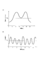
- the relationship between the traffic amount TR measured by the vibration sensor 46 and the time t (h) is schematically represented as shown in FIG. .
- the sensor node communication terminal according to the second embodiment is applied to a wireless sensor network system for bridges, the relationship between the traffic volume TR corresponding to the traffic volume of an automobile or a railway and the time t (h) Is detected by the vibration sensor 46 as sensor information.
- the average value of the traffic volume TR is represented by TR A.
- the vibration sensor 46 may be a load sensor on the bridge
- this assumption is to estimate the time by grasping the laws of trends such as traffic volume in one day. That is, it is assumed that there are many commuting hours in the morning and evening, and that there is a tendency that the nighttime is less than the daytime in the evening. Also, it is assumed that the pattern is different on weekends and holidays. In the case of a railway bridge, it is assumed that the first one after a certain amount of time has passed corresponds to the first departure time of 4:45. In addition, the characteristic of Fig.12 (a) is typical.
- the relationship between the light intensity P measured by the optical sensor 48 and the time t (day) is schematically represented as shown in FIG. .
- the sensor node communication terminal according to the second embodiment is applied to a farm wireless sensor network system
- the light intensity P corresponding to the sunshine time corresponding to the cycle of one day and the time t (day) Is detected as sensor information by the optical sensor 48.
- the average value of the light intensity P is expressed by P A.
- the characteristic of FIG.12 (b) is typical.
- the relationship between the amount of power generated by the photovoltaic device 40 P O and time t (day) is schematically shown in FIG. 13 expressed.
- the photovoltaic power generation device 40 shows a change of the power generation amount P O with respect to time t (day) according to the amount of received sunlight.
- the power generation amount P O exceeds a certain reference value A (corresponding to the operating points A1, A3, A5), when the power generation amount P O falls below a certain reference value A (corresponding to the operating points A2, A4, A6), when power generation amount P O represents the maximum power generation amount (corresponding to the operating point Qmax), in any of the timing when (corresponding to the operating point Qmin) for the power generation amount P O represents a minimum amount of power generation, the timer 44 by the timer clock 45 Can be adjusted.
- the normal power generation amount P O at the point A that the amount of power generation fell, i.e. a point close to the sunrise or sunset, the midpoint A1 and A2, the midpoint of A3 and A4, the midpoint of A5 and A6 is noon
- the reference value A may be set in a hysteresis relationship. That is, for example, the value calculated based on the maximum power generation amount MAX value and the minimum power generation amount MIN value can be used as the reference value A.
- the reference value A may be set by calculating the adjustment amount based on the standard deviation of the power generation amount P O for the past several days.
- the sensor node 20 (P) functioning as a communication terminal according to the second embodiment is in a state where it can receive transmission data from the host 10 side for a predetermined short period after transmission of wireless transmission data is completed. Low power consumption. That is, since it is not necessary to always turn on the receiver in the sensor node 20 (P), the power consumption is reduced.
- the wireless sensor network system to which the communication terminal and the communication terminal according to the second embodiment can be applied can operate in the same manner as the wireless sensor network system to which the communication terminal and the communication terminal according to the first embodiment can be applied. is there. Also, as in the first embodiment, the wireless sensor network system for bridges and the farm error! ⁇ ⁇ ⁇ link are not correct. It is also applicable.
- the second embodiment it is possible to provide a communication terminal capable of resetting time and capable of power saving communication and a wireless sensor network system to which this communication terminal can be applied.
- a plurality of sensor nodes laid on a structure such as a bridge can collect various sensor information at the laying location such as vibration, distortion, inclination, temperature, and various sensor information at substantially the same time.
- Various sensor information collected at substantially the same time is transmitted to a single host by wireless communication for analysis.
- the method of wireless transmission after collecting various types of sensor information from a plurality of sensor nodes at substantially equal intervals there may be a case in which communication is not established due to collision between the wireless signal data.
- the schematic timing chart of the data signal in the sensor node P1 is expressed as shown in FIG. 14A, and the schematic of the data signal in the sensor node P2 is shown.
- the timing chart is expressed as shown in FIG. 14B, and is a schematic timing chart of the data signal in the sensor node Pn, and is expressed as shown in FIG.
- a schematic timing chart of received data in the host H when there is no data collision is expressed as shown in FIG.
- a schematic timing chart of received data in the host H when there is a data collision is expressed as shown in FIG.
- the schematic timing chart of the data signal in the sensor node P1 is expressed as shown in FIG.
- a schematic timing chart of the signal is expressed as shown in FIG. 16B
- a schematic timing chart of the data signal in the sensor node Pn is expressed as shown in FIG.
- various sensor information i collected during the time ti ⁇ ti + 1 is transmitted to the host H during the time t1 ⁇ t2 after the elapse of the timing ⁇ t1 from the time ti + 1.
- various sensor information i collected during the time ti ⁇ ti + 1 is transmitted to the host H during the time t2 ⁇ t3 after the timing ⁇ t2 has elapsed since the time ti + 1.
- various sensor information i collected during the time ti ⁇ ti + 1 is transmitted to the host H during the time tn ⁇ tn + 1 after the elapse of the timing ⁇ tn from the time ti + 1. .
- a plurality of sensor nodes P1, P2, When transmitting various sensor information i collected at substantially the same time ti ⁇ ti + 1 to the host H by wireless communication, the plurality of sensor nodes P1, P2,. It is possible to avoid collision of radio signal data by changing the timing until transmission to the host H by communication at a plurality of sensor nodes P1, P2,.
- timing ⁇ t to be changed in the plurality of sensor nodes P1, P2,... Pn may be set in advance for each of the plurality of sensor nodes P1, P2,.
- the timing ⁇ t to be changed by the plurality of sensor nodes P1, P2,... Pn is a control signal (T Xh in the second wireless transmission data transmitted from the host H to the plurality of sensor nodes P1, P2 ,. : It is possible to readjust according to FIG. 6B and FIG.
- the method of substantially synchronizing the timings of the various sensor information i among the plurality of sensor nodes P1, P2,..., Pn is the same as that of the wireless sensor network system according to the first embodiment shown in FIGS. This is as described with reference to the timing chart and the flowcharts of FIGS.
- Communication terminal (sensor node) 20 for bridges wireless sensor network system 310 can be applied to according to the third embodiment, as shown in FIG. 17, a plurality of sensor nodes 20 11, 20 12, ..., 20 11 ( H), 20 12 (H) , ... ⁇ 20 21, 20 22, ..., 20 21 (H), 20 22 (H), ... ⁇ 20 31, 20 32, ..., 20 31 (H), 20 32 ( H), ... ⁇ 20 41, 20 42, ..., 20 41 (H), 20 42 (H), ... , a plurality of sensor nodes 20 11, 20 12, ..., 20 11 (H), 20 12 (H ), ... ⁇ 20 21, 20 22, ... 20 21 (H), 20 22 (H), ...
- the timing control may be executed between the adjacent hosts 10 1 , 10 2 , 10 3, and 10 4 .
- collision of radio signal data can be avoided so that time does not overlap between the groups of adjacent hosts 10 1 , 10 2 , 10 3, and 10 4 .
- the timing ⁇ t changed by a plurality of sensor nodes may be set in advance for each of the plurality of sensor nodes.
- timing ⁇ t to be changed by the plurality of sensor nodes can be readjusted by a control signal (T Xh : FIG. 6B, FIG. 7) in the second wireless transmission data transmitted from the host to the plurality of sensor nodes. is there.
- the hosts 10 1 , 10 2 , 10 3, and 10 4 may be disposed at a connection portion between the columns 301, 302, 303, and 304 having a predetermined height and the road (or railroad track) 305.
- the suspension bridge structure wire 307 is stretched between the columns 301, 303, 302, and 304, and between the suspension bridge structure wire 307 and the connection portion of the road (or railroad track) 305 in a substantially vertical direction.
- 308 is arranged, and the road (or railroad track) 305 is supported by the columns 301, 302, 303, and 304.
- a plurality of sensor nodes 20 11 , 20 12 ,..., 20 21 , 20 22 ,..., 20 31 , 20 32 ,..., 20 41 , 20 42 , etc. are composed of a plurality of wires 307 and a road (or railroad track) 305. It may be arranged at a connection part (indicated by a black circle).
- a plurality of sensor nodes 20 11 (H), 20 12 (H),... 20 21 (H), 20 22 (H),... 20 31 (H), 20 32 (H) ,. (H), 20 42 (H),... May be arranged at a connection portion (indicated by a white circle) between the wire 307 and the wire 308 of the suspension bridge structure.
- the plurality of sensor nodes 20 11 , 20 12 ,..., 20 11 (H), 20 12 (H),... Can be wirelessly transmitted / received to / from the host 10 1. 21, 20 22, ..., 20 21 (H), 20 22 (H), ... is capable wireless transmitted and received between the host 10 2, a plurality of sensor nodes 20 31, 20 32, ..., 20 31 ( H), 20 32 (H),... Can be wirelessly transmitted to and received from the host 10 3 , and a plurality of sensor nodes 20 41 , 20 42 ,..., 20 41 (H), 20 42 (H),. Can be wirelessly transmitted to and received from the host 10 4 .
- Information collected in the hosts 10 1 , 10 2 , 10 3, and 10 4 is supplied to a cloud computing system using an Internet line or the like, and can be integratedly managed.
- the communication terminal according to the third embodiment and the wireless sensor network system for bridge 310 to which the communication terminal can be applied apply the communication terminal and the communication terminal according to the first and second embodiments. It can operate in the same way as a possible wireless sensor network system.
- the configuration of the sensor node 20 (P) functioning as a communication terminal according to the third embodiment can employ the same configuration as that of the first embodiment and the second embodiment.
- the third embodiment it is possible to provide a communication terminal capable of avoiding collision of radio signal data and capable of power saving communication and a wireless sensor network system to which this communication terminal can be applied.
- FIG. 1 A schematic configuration of a wireless sensor network system 100 to which a communication terminal (sensor node) according to the fourth embodiment can be applied is represented as shown in FIG.
- a wireless sensor network system 100 to which a communication terminal (sensor node) according to the fourth embodiment can be applied includes a plurality of sensor nodes P 1 , P 2 ,..., P i , P i + 1, ..., and P n, a plurality of sensor nodes P 1, P 2, ⁇ , P i, P i + 1, ..., constantly or periodically receives first radio transmission data from the P n Possible host 10.
- the distance between the plurality of sensor nodes P 1 , P 2 ,..., P i , P i + 1 ,..., P n and the host 10 is L 1 , L 2 ,. i , L i + 1 ,..., L n .
- the reception frequency in a host is more frequent than the transmission frequency of a sensor node.
- the plurality of sensor nodes P 1 , P 2 ,..., P i , P i + 1 ,..., P n are the first from the host 10 side for a predetermined short period after the transmission of the first wireless transmission data. 2 Wireless transmission data can be received.
- the first radio transmission data a plurality of sensor nodes P 1, P 2, ⁇ , P i, P i + 1, ..., a P n, at a predetermined timing, is transmitted to the host 10
- the second wireless transmission data is transmitted from the host 10 side to the plurality of sensor nodes P 1 , P 2 ,..., P i , P i + 1 only for a predetermined short period after the transmission of the first wireless transmission data. ,..., Pn .
- Fourth wireless sensor network system 100 can be applied to a communication terminal according to the embodiment of the plurality of sensor nodes P 1, P 2, ⁇ , P i, P i + 1, ..., in P n, wireless Since the transmission data from the host 10 side can be received only for a predetermined short period after the transmission of the transmission data is completed, the power consumption is reduced. That is, a plurality of sensor nodes P 1, P 2, ⁇ , P i, P i + 1, ..., there is no need to have to constantly turn on the receiver in P n, are low power consumption .
- the information collected in the host 10 is supplied to the cloud computing system using the Internet line or the like, and can be integratedly managed.
- wired communication via the Internet line or wireless communication different from the wireless communication in this case can be applied.
- the fourth wireless sensor network system 100 can be applied to a communication terminal according to the embodiment, the plurality of sensor nodes P 1, P 2, ⁇ , P i, P i + 1, ..., P n and the host
- the data communication speed D (kbps) between 10 (H) can be changed.
- the reception sensitivity S is increased and the transmission distance L is increased. As a result, the transmission time becomes longer. On the other hand, when there is sufficient reception sensitivity S, the communication speed D (kbps) is increased. As a result, the transmission time can be shortened, low power consumption operation becomes possible, and necessary power can be suppressed.
- a wireless sensor network system having a plurality of communication speed functions can be provided, which is suitable for applications where a wide area such as a bridge, a farm, or a forest is desired to be covered.
- the fourth wireless sensor network system 100 can be applied to a communication terminal according to the embodiment, the plurality of sensor nodes P 1, P 2, ⁇ , P i, P i + 1, ..., P n and the host By making it possible to change the data communication speed D (kbps) between 10 (H), the total transmission data amount can be suppressed as a result.
- the data communication speed D can be reduced, and as a result, a small amount of data, That is, the total transmission data amount can be suppressed.
- sensor information such as temperature, humidity, and vibration is detected as continuous data. If low data communication rate of the communication is stable, the host 10 (H), the sensor node P 1, P 2, ⁇ , P i, P i + 1, ..., data communication speed relative to P n It is possible to issue a command to increase As a result, the sensor nodes P 1 , P 2 ,..., P i , P i + 1 ,..., P n can transmit a larger amount of data to the host 10 (H).
- a plurality of sensor nodes P 1, P 2, ⁇ , P i, P i + 1, ... if it is desired to operate in an energy harvester to P n, a plurality of sensor nodes P 1, P 2 ,..., P i , P i + 1 ,..., P n , it is desirable that there is no need to transmit signals for maintaining the wireless sensor network in vain. It is possible to implement a wireless sensor network system in which data transmission from the sensor node is performed at a low communication speed, reception opportunities are set in the sensor node for only a short period, and power is saved in the sleep mode during other periods.
- FIG. 19 (a) a schematic timing chart of a data signal in the host H is represented as shown in FIG. 19 (a), and FIG. A schematic timing chart of the data signal in the sensor node Pi corresponding to is represented as shown in FIG.
- the sensor node Pi transmits the wireless transmission data T xP1-1 to the host H at the initial communication speed of 1 kbps, and the host H transmits the wireless reception data R xC1 from the sensor node Pi.
- ⁇ 1 is received, for example, with a received field strength (RSSI) of about ⁇ 100 dBm.
- RSSI received field strength
- the sensor node Pi opens the reception window R xP1-1 and sets the wireless transmission data from the host H to a reception standby state (talk / after / listen mode).
- the sensor node Pi transmits the wireless transmission data T xP1-2 to the host H at the communication speed of 1 kbps, and the host H transmits the sensor node Pi between the times t3 and t4.
- the radio reception data RxC1-2 from is received with RSSI of about -90 dBm, for example.
- the host H transmits wireless transmission data TxC1-1 including an instruction to increase the communication speed to the sensor node Pi in the master rate mode (for example, communication Instructions to increase the speed to 10 kbps).
- an instruction to increase the communication speed to the sensor node Pi in the master rate mode for example, communication Instructions to increase the speed to 10 kbps.
- the sensor node Pi transmits the wireless transmission data T xP1-3 to the host H at a communication speed of 10 kbps, and the host H receives the wireless reception data R xC1 from the sensor node Pi. -3 is received, for example, with an RSSI of about -93 dBm.
- the sensor node Pi opens the reception window R xP1-3 and puts data from the host H into a reception standby state (talk / after / listen mode).
- the communication speed is increased from the initial communication speed of 1 kbps to, for example, 10 kbps.
- the present invention is not limited to this.
- the communication speed may be, for example, 12.5 kbps, 20 kbps,..., 50 kbps, 100 kbps, 200 kbps (supporting IEEE specifications) from the initial communication speed of 1 kbps. 400 kbps is also applicable.
- the time required for transmission by the sensor node is 100 msec for 1 kbps and 10 msec for 10 kbps, and the power consumption of the sensor node can be significantly reduced.
- the amount of data that can be transmitted by the sensor node in one transmission is 100 bits for 1 kbps, 1000 bits for 10 kbps, and a large amount of data can be transmitted.
- the maximum time for one transmission is determined to be 50 msec by the Radio Law, and the amount of data that can be transmitted is limited when the communication speed is low.
- the communication distance that can be transmitted can be extended even if the same transmission power is used as an advantage of low communication speed. This is because the receiving sensitivity of the receiver can be increased as the communication speed decreases.
- the relationship between the transmission distance L (m) and the reception sensitivity S (dBm) between the host H and the sensor node Pi is schematically illustrated.
- the relationship between the communication speed D (kbps) and the reception sensitivity S (dBm) between the host H and the sensor node Pi is schematically represented as shown in FIG. Is done.
- the fourth wireless sensor network system 100 can be applied to a communication terminal according to the embodiment, the plurality of sensor nodes P 1, P 2, ⁇ , P i, P i + 1, ..., P n and the host
- the data communication speed D (kbps) between 10 (H) can be changed, and is effective when used in a relatively wide area (several kilometers) (bridge, tunnel, farm, etc.).
- Communication nodes for low power, especially sensor nodes that use energy harvesters (several centimeters of solar panels, etc.) as power sources are effective when network establishment communication (synchronous communication) is difficult due to power requirements. is there.
- a schematic block configuration of the host 10 (H) capable of wireless communication with the sensor node communication terminal according to the fourth embodiment includes a memory 12 and a control connected to the memory 12 as shown in FIG. Unit 14, a radio transmission / reception unit (RF) 16 connected to control unit 14, and an antenna 18 connected to radio transmission / reception unit (RF) 16.
- RF radio transmission / reception unit
- the host 10 (H) collects sensing data from the sensor nodes P1 to Pn via wireless communication.
- the host 10 (H) has a function capable of dealing with various communication speeds.
- the host 10 (H) has a function of measuring the RSSI of the received radio wave.
- the host 10 (H) has a function of designating a change in communication speed for the sensor nodes P1 to Pn according to RSSI (master rate mode).
- This communication speed change designation signal may be included in the data request signal or control signal (T Xh : FIGS. 6B and 7) in the second wireless transmission data. For this reason, as shown in FIG.
- the wireless transmission / reception unit (RF) 16 includes an RSSI unit 17 that measures the received electric field strength (RSSI) of the received radio wave, and the control unit 14 measures the RSSI unit 17.
- RSSI received electric field strength
- a master rate unit 13 that designates a change in communication speed for the sensor nodes P1 to Pn according to the RSSI is provided.
- a communication speed change designation signal SVM that designates a change in communication speed for the sensor nodes P1 to Pn is supplied from the control unit 14 to the wireless transmission / reception unit (RF) 16, and the wireless transmission / reception unit (RF) 16 causes the antenna 18 to be connected.
- SVM communication speed change designation signal
- the schematic block configuration of the sensor node 20 (P) functioning as a communication terminal according to the fourth embodiment is a place where sensor information is installed at an independent timing, as shown in FIG.
- RF wireless transmission / reception unit
- an antenna 28 that is connected to the wireless transmission / reception unit 26 and can wirelessly transmit sensor information or a result obtained by processing the sensor information, a power supply unit 32 connected to the control unit 24, and a timer 30 connected to the control unit 24.
- the sensor node 20 (P) can receive transmission data from the host 10 side for a predetermined short period after transmission of wireless transmission data (sensing data) is completed. That is, in the first embodiment, as described with reference to FIGS. 6 to 9, the sensor nodes P1 to Pn have a function of detecting the presence or absence of communication from the host H immediately after sensing data transmission ( Talk after listen mode).
- Sensor nodes P1 to Pn are equipped with various sensors and transmit the measured values or the calculation results of the measured values to the host H by wireless communication.
- the sensor nodes P1 to Pn have a function of changing the communication speed in accordance with an instruction from the host (slave rate mode).
- the wireless transmission / reception unit (RF) 26 includes a reception unit 27 that receives an instruction from the host, and the control unit 24 responds to the instruction from the host received by the reception unit 27. And a slave rate unit 25 for instructing the host 10 (H) to change the communication speed.
- the communication speed change instruction signal SVS to the host 10 (H) is supplied from the control unit 24 to the wireless transmission / reception unit (RF) 26, and is transmitted from the wireless transmission / reception unit (RF) 26 to the sensor nodes P1 to Pn via the antenna 28.
- Sent Other configurations are the same as the configuration of the sensor node 20 (P) (FIG. 4B) in the first embodiment.
- a control unit 42 connected to the sensor 21 and capable of processing sensor information, a memory 22 connected to the control unit 42, a wireless transmission / reception unit (RF) 26 connected to the control unit 42, and a wireless transmission / reception unit 26 It includes an antenna 28 that is connected and can wirelessly transmit sensor information or a result obtained by calculating sensor information, a power supply unit 32 connected to the control unit 42, and a timer 44 connected to the control unit 42.
- the sensor node 20 (P) can receive transmission data from the host 10 side for a predetermined short period after transmission of wireless transmission data (sensing data) is completed.
- the power supply unit 32 includes a photovoltaic power generation device 40 and a power generation amount detection device 50 that is connected to the photovoltaic power generation device 40 and measures the amount of photovoltaic power generation.
- the power generation amount detection device 50 that measures the amount of photovoltaic power generation may have a peak power tracking function.
- the power storage unit 54 may be connected to the power supply unit 32.
- a capacitor, a lithium ion capacitor, an electric double-layer capacitor (EDLC), or the like can be applied.
- the power storage device 54 may be built in the power supply unit.
- the sensor nodes P1 to Pn have a function of detecting the presence / absence of communication from the host H immediately after sensing data transmission (talk / talk). After listen mode).
- the sensor nodes P1 to Pn have a function of changing the communication speed in accordance with an instruction from the host (slave rate mode).
- the wireless transmission / reception unit (RF) 26 includes a receiving unit 27 that receives an instruction from the host, and the control unit 24 responds to the instruction from the host received by the receiving unit 27.
- a slave rate unit 43 is provided for instructing the change of the communication speed to 10 (H).
- the communication speed change instruction signal SVS to the host 10 (H) is supplied from the control unit 42 to the wireless transmission / reception unit (RF) 26, and is transmitted from the wireless transmission / reception unit (RF) 26 to the sensor nodes P 1 to Pn via the antenna 28.
- Other configurations are the same as the configuration of the sensor node 20 (P) (FIG. 10) in the second embodiment.
- the fourth embodiment by enabling the data communication speed between the plurality of sensor nodes and the host to be changed, the total transmission data amount can be suppressed, and the communication terminal capable of power saving communication and the communication terminal Can be provided.
- the communication terminal and the wireless sensor network system of the present invention can be applied to a wide area such as a bridge, a farm, and a forest, and various sensor information such as temperature, humidity, vibration, and strain are continuously transmitted in a plurality of sensor node communication terminals. It can be applied to system applications that can be acquired as data and wirelessly transmitted to a host with low power consumption.
Landscapes
- Engineering & Computer Science (AREA)
- Computer Networks & Wireless Communication (AREA)
- Signal Processing (AREA)
- Arrangements For Transmission Of Measured Signals (AREA)
- Mobile Radio Communication Systems (AREA)
- Bridges Or Land Bridges (AREA)
- Quality & Reliability (AREA)
- Physics & Mathematics (AREA)
- Electromagnetism (AREA)
Abstract
自立したタイミングでセンサ情報を設置された場所で収集可能なセンサ(21)と、センサ(21)に接続され、センサ情報を演算処理可能な制御部(24)と、制御部(24)に接続されたメモリ(22)と、制御部(24)に接続された無線送受信部(26)と、無線送受信部(26)に接続され、センサ情報若しくはセンサ情報を演算処理した結果を無線送信可能なアンテナ(28)と、制御部(24)に接続された電源部(32)と、制御部(24)に接続されたタイマ(30)とを備え、無線送信データを送信終了後の所定の期間、ホスト側からの第2無線送信データを受信可能としたセンサノード通信端末(20)およびこのセンサノード通信端末(20)を複数適用可能な無線センサネットワークシステム。省電力通信可能な通信端末および無線センサネットワークシステムを提供することができる。
Description
本発明は、通信端末および無線センサネットワークシステムに関し、特に省電力通信可能な通信端末およびこの通信端末を適用可能な無線センサネットワークシステムに関する。
複数のセンサノードにおいてさまざまなエネルギー源から電力を取得(エネルギーハーべスティング、電池など)し、かつスイッチ情報や温度、圧力などのセンサ情報をホストに対して片方向若しくは双方向に無線データ通信する無線センサネットワークシステムが開示されている(例えば、特許文献1参照。)。
橋梁、道路、鉄道、建造物などの社会インフラシステムの老朽化は社会問題となっている。また、その老朽化対策には莫大な費用がかかるため、これらの社会インフラシステムの寿命を延ばすための対策も求められる。
従来の無線センサネットワークシステムにおいては、複数のセンサノードは、無線送信データを送信終了後も常時ホストからの信号を受信できる状態を維持するために、複数のセンサノード内の受信器を常時オンさせておく必要がある。
また、従来の無線センサネットワークシステムにおいては、センサノードが、送信だけでなく受信機能も持とうとすると、自センサノードが送信していないときは、常に受信回路をオンにして受信待ち受け状態にしておかないといけなかった。このため消費電力が相対的に大きい。
本発明の目的は、省電力通信可能な通信端末およびこの通信端末を適用可能な無線センサネットワークシステムを提供することにある。
本発明の一態様によれば、自立したタイミングでセンサ情報を設置された場所で収集可能なセンサと、前記センサに接続され、前記センサ情報を演算処理可能な制御部と、前記制御部に接続されたメモリと、前記制御部に接続された無線送受信部と、前記無線送受信部に接続され、前記センサ情報若しくは前記センサ情報を演算処理した結果を無線送信可能なアンテナと、前記制御部に接続された電源部と、前記制御部に接続されたタイマとを備え、第1無線送信データを送信終了後の所定の期間、ホスト側からの第2無線送信データを受信可能としたセンサノード通信端末が提供される。
本発明の他の態様によれば、制御部と、前記制御部に接続されたメモリと、前記制御部に接続された無線送受信部と、前記無線送受信部に接続されたアンテナとを備え、複数のセンサノードからのセンシングデータを無線通信を介して収集すると共に、受信した電波の受信電界強度に応じて、複数のセンサノードに対して通信速度の変更を指定するホスト通信端末が提供される。
本発明の他の態様によれば、複数のセンサノードと、前記複数のセンサノードからの第1無線送信データを常時もしくは定期的に受信可能なホストとを備え、前記センサノードは、前記第1無線送信データを送信終了後の所定の期間、前記ホスト側からの第2無線送信データを受信可能としたことを特徴とする無線センサネットワークシステムが提供される。
本発明の他の態様によれば、自立したタイミングでセンサ情報を設置された場所で収集可能なセンサと、前記センサに接続され、前記センサ情報を演算処理可能な制御部と、前記制御部に接続されたメモリと、前記制御部に接続された無線送信部と、前記無線送信部に接続され、前記センサ情報若しくは前記センサ情報を演算処理した結果を無線送信可能なアンテナと、前記制御部に接続された電源部と、前記制御部に接続されたタイマとを備える複数のセンサノードと、前記複数のセンサノードからの無線送信データを常時もしくは定期的に受信可能なホストとを備える無線センサネットワークシステムが提供される。
本発明によれば、省電力通信可能な通信端末およびこの通信端末を適用可能な無線センサネットワークシステムを提供することができる。
次に、図面を参照して、本発明の実施の形態を説明する。以下の図面の記載において、同一又は類似の部分には同一又は類似の符号を付している。ただし、図面は模式的なものであり、各構成部品の厚みと平面寸法との関係等は現実のものとは異なることに留意すべきである。したがって、具体的な厚みや寸法は以下の説明を参酌して判断すべきものである。又、図面相互間においても互いの寸法の関係や比率が異なる部分が含まれていることはもちろんである。
又、以下に示す実施の形態は、この発明の技術的思想を具体化するための装置や方法を例示するものであって、この発明の実施の形態は、各構成部品の材質、形状、構造、配置等を下記のものに特定するものでない。この発明の実施の形態は、特許請求の範囲において、種々の変更を加えることができる。
[第1の実施の形態]
(無線センサネットワークシステム)
第1の実施の形態に係る通信端末(センサノード)20を適用可能な無線センサネットワークシステム100の模式的構成は、図1に示すように表される。
(無線センサネットワークシステム)
第1の実施の形態に係る通信端末(センサノード)20を適用可能な無線センサネットワークシステム100の模式的構成は、図1に示すように表される。
第1の実施の形態に係る通信端末(センサノード)20を適用可能な無線センサネットワークシステム100は、図1に示すように、複数のセンサノード20(P1、P2、・・・、Pi、Pi+1、…、Pn)と、複数のセンサノード20からの第1無線送信データを常時もしくは定期的に受信可能なホスト10とを備える。ここで、定期的に受信する場合、ホスト10における受信頻度は、センサノード20の送信頻度よりも頻繁である。
ホスト10は、基地局であり、例えば、所定の高さを有する支柱15上に配置されていても良い。
複数のセンサノード20は、図6の説明において後述するように、第1無線送信データを送信終了後の所定の短い期間だけ、ホスト10側からの第2無線送信データを受信可能である。ここで、第1無線送信データは、複数のセンサノード20(P1、P2、・・・、Pi、Pi+1、…、Pn)から、所定のタイミングで、ホスト10に対して送信される。
また、第2無線送信データは、第1無線送信データを送信終了後の所定の短い期間だけ、ホスト10側から複数のセンサノード20(P1、P2、・・・、Pi、Pi+1、…、Pn)に対して送信される。
第1の実施の形態に係る通信端末20を適用可能な無線センサネットワークシステム100は、複数のセンサノード20(P1、P2、・・・、Pi、Pi+1、…、Pn)において、無線送信データを送信終了後の所定の短い期間だけ、ホスト10側からの送信データを受信できる状態としたことによって、低消費電力化されている。すなわち、複数のセンサノード20(P1、P2、・・・、Pi、Pi+1、…、Pn)において、無線送信データを送信終了後も常時受信できる状態とする場合に比べて、複数のセンサノード20(P1、P2、・・・、Pi、Pi+1、…、Pn)内の受信器を常時オンさせておく必要が無いため、低消費電力化されている。
ホスト10において収集された情報はインターネット回線などを利用してクラウドコンピューティングシステムに供給されて、統合管理可能である。
複数のセンサノード20(P1、P2、・・・、Pi、Pi+1、…、Pn)は、図4(b)の説明において後述するように、自立したタイミングでセンサ情報を設置された場所で収集可能なセンサ21と、センサ21に接続されたメモリ22と、メモリ22に接続され、センサ情報を演算処理可能な制御部24と、制御部24に接続された無線送受信部(RF)26と、無線送受信部26に接続され、センサ情報若しくはセンサ情報を演算処理した結果を無線送信可能なアンテナ28と、制御部24に接続された電源部32と、制御部24に接続されたタイマ30とを備える。
ここで、メモリ22には、センサ21において取得されたセンサ情報が記憶される。
センサ21において取得されるセンサ情報には、通信端末(センサノード)20を適用する無線センサネットワークシステム100の用途に応じて、例えば、光、温度、湿度、圧力、振動、歪み、傾斜、スイッチ情報などが含まれる。
電源部32には、例えば、ソーラパネルなどの環境発電装置を主として使う。一方、これを電池に置き換えたり、ハイブリッドに併設したりする構造でも適用可能である。電池の長寿命化など目的は同様であるからである。
(橋梁用無線センサネットワークシステム)
第1の実施の形態に係る通信端末(センサノード)20を適用可能な無線センサネットワークシステムとして、橋梁用無線センサネットワークシステム300の模式的鳥瞰構成は、図2に示すように表される。
第1の実施の形態に係る通信端末(センサノード)20を適用可能な無線センサネットワークシステムとして、橋梁用無線センサネットワークシステム300の模式的鳥瞰構成は、図2に示すように表される。
第1の実施の形態に係る通信端末(センサノード)20を適用可能な橋梁用無線センサネットワークシステム300は、図2に示すように、複数のセンサノード2011、2012、…・2021、2022、…・2031、2032、…・2041、2042、…と、複数のセンサノード2011、2012、…・2021、2022、…・2031、2032、…・2041、2042、…からの第1無線送信データを常時もしくは定期的に受信可能なホスト101・102・103・104とを備える。ここで、定期的に受信する場合、ホスト10における受信頻度は、センサノード20の送信頻度よりも頻繁である。
ホスト101・102・103・104は、例えば、所定の高さを有する支柱301・302・303・304と道路(もしくは鉄道線路)305との接続部に配置されていても良い。
支柱301・302・303・304と道路(もしくは鉄道線路)305との間には、複数本のワイヤ306が接続されており、支柱301・302・303・304によって、道路(もしくは鉄道線路)305を支えている。
複数のセンサノード2011、2012、…・2021、2022、…・2031、2032、…・2041、2042、…は、複数本のワイヤ306と道路(もしくは鉄道線路)305との接続部に配置されていても良い。
複数のセンサノード2011、2012、…は、例えば、ホスト101との間で無線送受信可能であり、同様に、複数のセンサノード2021、2022、…は、ホスト102との間で無線送受信可能であり、複数のセンサノード2031、2032、…は、ホスト103との間で無線送受信可能であり、複数のセンサノード2041、2042、…は、ホスト104との間で無線送受信可能である。
複数のセンサノード2011、2012、…は、第1無線送信データを送信終了後の所定の短い期間だけ、ホスト101側からの第2無線送信データを受信可能である。第1無線送信データは、複数のセンサノード2011、2012、…から、所定のタイミングで、ホスト101に対して送信される。また、第2無線送信データは、第1無線送信データを送信終了後の所定の短い期間だけ、ホスト101側から複数のセンサノード2011、2012、…に対して送信される。以下同様である。
第1の実施の形態に係る通信端末20を適用可能な橋梁用無線センサネットワークシステム300は、複数のセンサノード2011、2012、…・2021、2022、…・2031、2032、…・2041、2042、…において、無線送信データを送信終了後の所定の短い期間だけ、ホスト101・102・103・104側からの送信データを受信できる状態としたことによって、低消費電力化されている。すなわち、複数のセンサノード内の受信器を常時オンさせておく必要が無いため、低消費電力化されている。
ホスト101・102・103・104において収集された情報はインターネット回線などを利用してクラウドコンピューティングシステムに供給されて、統合管理可能である。
ここで、複数のセンサノード2011、2012、…・2021、2022、…・2031、2032、…・2041、2042、…は、図4(b)の説明において後述するように、自立したタイミングでセンサ情報を設置された場所で収集可能なセンサ21と、センサ21に接続され、センサ情報を演算処理可能な制御部24と、制御部24に接続されたメモリ22と、制御部24に接続された無線送受信部(RF)26と、無線送受信部26に接続され、センサ情報若しくはセンサ情報を演算処理した結果を無線送信可能なアンテナ28と、制御部24に接続された電源部32と、制御部24に接続されたタイマ30とを備える。ここで、メモリ22には、センサ21において取得されたセンサ情報が記憶される。センサ情報には、例えば、光、温度、湿度、圧力、振動、歪み、傾斜、張力などが含まれる。
電源部32には、例えば、ソーラパネルなどの環境発電装置を主として使う。一方、これを電池に置き換えたり、ハイブリッドに併設したりする構造でも適用可能である。
なお、橋梁の支柱間の中心近傍に配置されるセンサノードでは、両側に配置されるホストのいずれかを選択して無線送受信を実施しても良い。また、第3の実施の形態において後述するように、データ衝突を回避する方法を適用しても良い。
(農場用無線センサネットワークシステム)
第1の実施の形態に係る通信端末(センサノード)20を適用可能な無線センサネットワークシステムとして、農場用無線センサネットワークシステム200の模式的鳥瞰構成は、図3に示すように表される。農場用無線センサネットワークシステム200は、図3に示すように、複数の小規模な農場用無線センサネットワークシステム2001・2002・…・200mから構成されていても良い。
第1の実施の形態に係る通信端末(センサノード)20を適用可能な無線センサネットワークシステムとして、農場用無線センサネットワークシステム200の模式的鳥瞰構成は、図3に示すように表される。農場用無線センサネットワークシステム200は、図3に示すように、複数の小規模な農場用無線センサネットワークシステム2001・2002・…・200mから構成されていても良い。
複数の小規模な農場用無線センサネットワークシステム2001・2002・…・200mは、例えば、栽培される作物単位で分かれていても良い。
第1の実施の形態に係る通信端末(センサノード)20を適用可能な農場用無線センサネットワークシステム200は、図3に示すように、複数のセンサノード2011・2012・…・201n、2021・2022・…・202n、・・・、20m1・20m2・…・20mnと、複数のセンサノード2011・2012・…・201n、2021・2022・…・202n、・・・、20m1・20m2・…・20mnからの第1無線送信データを常時もしくは定期的に受信可能な複数のホスト101・102・…・10mとを備える。ここで、定期的に受信する場合、ホスト10における受信頻度は、センサノード20の送信頻度よりも頻繁である。
複数のセンサノード2011・2012・…・201nは、例えば、ホスト101との間で無線送受信可能であり、同様に、複数のセンサノード2021・2022・…・202nは、ホスト102との間で無線送受信可能であり、・・・、複数のセンサノード20m1・20m2・…・20mnは、ホスト10mとの間で無線送受信可能である。
複数のセンサノード2011・2012・…・201n、2021・2022・…・202n、・・・、20m1・20m2・…・20mnは、それぞれの作物に応じたセンサ情報を取得するためのセンサ21を備える。
複数のセンサノード2011・2012・…・201nは、第1無線送信データを送信終了後の所定の短い期間だけ、ホスト101側からの第2無線送信データを受信可能である。第1無線送信データは、複数のセンサノード2011・2012・…・201nから、所定のタイミングで、ホスト101に対して送信される。また、第2無線送信データは、第1無線送信データを送信終了後の所定の短い期間だけ、ホスト101側から複数のセンサノード2011・2012・…・201nに対して送信される。以下同様である。
ホスト101・102・103・…・10mにおいて収集された情報はインターネット回線などを利用してクラウドコンピューティングシステムに供給されて、統合管理可能である。
第1の実施の形態に係る通信端末20を適用可能な農場用無線センサネットワークシステム200は、複数のセンサノード2011・2012・…・201n、2021・2022・…・202n、・・・、20m1・20m2・…・20mnにおいて、無線送信データを送信終了後の所定の短い期間だけ、ホスト101・102・…・10m側からの送信データを受信できる状態としたことによって、低消費電力化されている。すなわち、複数のセンサノード内の受信器を常時オンさせておく必要が無いため、低消費電力化されている。
複数のセンサノード2011・2012・…・201n、2021・2022・…・202n、・・・、20m1・20m2・…・20mnは、図4(b)の説明において後述するように、自立したタイミングでセンサ情報を設置された場所で収集可能なセンサ21と、センサ21に接続され、センサ情報を演算処理可能な制御部24と、制御部24に接続されたメモリ22と、制御部24に接続された無線送受信部(RF)26と、無線送受信部26に接続され、センサ情報若しくはセンサ情報を演算処理した結果を無線送信可能なアンテナ28と、制御部24に接続された電源部32と、制御部24に接続されたタイマ30とを備える。ここで、メモリ22には、センサ21において取得されたセンサ情報が記憶される。センサ情報には、例えば、農場内の設置された場所における光、温度、湿度、気圧、振動、歪み、傾斜、スイッチ情報などが含まれる。
電源部32には、例えば、ソーラパネルなどの環境発電装置を主として使う。一方、これを電池に置き換えたり、ハイブリッドに併設したりする構造でも適用可能である。
(通信端末:ホスト)
第1の実施の形態に係るセンサノード通信端末と無線通信可能なホスト10(H)の模式的ブロック構成は、図4(a)に示すように、メモリ12と、メモリ12に接続された制御部14と、制御部14に接続された無線送受信部(RF)16と、無線送受信部(RF)16に接続されたアンテナ18とを備える。メモリ12には、ホスト10とセンサノード20との無線通信に必要な制御情報が格納される。制御部14は、メモリ12に格納された制御情報に基づいて、ホスト10とセンサノード20との無線通信制御を実行する。無線送受信部(RF)16は、ホスト10・センサノード20間の無線データをアンテナ18を介して送受信する。ここで、ホスト10(H)は、基地局であり、電源部を特に設ける必要がないため、図4(a)には図示されていないが、用途に応じてさまざまなエネルギー源から電力を取得(エネルギーハーべスティング)する電源部構成を備えていても良い。ホスト10(H)は、センサノード20(P)からの第1無線送信データを常時もしくは定期的に受信可能である。ここで、定期的に受信する場合、ホストにおける受信頻度は、センサノードの送信頻度よりも頻繁である。
第1の実施の形態に係るセンサノード通信端末と無線通信可能なホスト10(H)の模式的ブロック構成は、図4(a)に示すように、メモリ12と、メモリ12に接続された制御部14と、制御部14に接続された無線送受信部(RF)16と、無線送受信部(RF)16に接続されたアンテナ18とを備える。メモリ12には、ホスト10とセンサノード20との無線通信に必要な制御情報が格納される。制御部14は、メモリ12に格納された制御情報に基づいて、ホスト10とセンサノード20との無線通信制御を実行する。無線送受信部(RF)16は、ホスト10・センサノード20間の無線データをアンテナ18を介して送受信する。ここで、ホスト10(H)は、基地局であり、電源部を特に設ける必要がないため、図4(a)には図示されていないが、用途に応じてさまざまなエネルギー源から電力を取得(エネルギーハーべスティング)する電源部構成を備えていても良い。ホスト10(H)は、センサノード20(P)からの第1無線送信データを常時もしくは定期的に受信可能である。ここで、定期的に受信する場合、ホストにおける受信頻度は、センサノードの送信頻度よりも頻繁である。
(通信端末:センサノード)
一方、第1の実施の形態に係る通信端末として機能するセンサノード20(P)の模式的ブロック構成は、図4(b)に示すように、自立したタイミングでセンサ情報を設置された場所で収集可能なセンサ21と、センサ21に接続され、センサ情報を演算処理可能な制御部24と、制御部24に接続されたメモリ22と、制御部24に接続された無線送受信部(RF)26と、無線送受信部26に接続され、センサ情報若しくはセンサ情報を演算処理した結果を無線送信可能なアンテナ28と、制御部24に接続された電源部32と、制御部24に接続されたタイマ30とを備える。ここで、センサノード20(P)は、無線送信データを送信終了後の所定のわずかの期間だけ、ホスト10側からの送信データを受信可能である。
一方、第1の実施の形態に係る通信端末として機能するセンサノード20(P)の模式的ブロック構成は、図4(b)に示すように、自立したタイミングでセンサ情報を設置された場所で収集可能なセンサ21と、センサ21に接続され、センサ情報を演算処理可能な制御部24と、制御部24に接続されたメモリ22と、制御部24に接続された無線送受信部(RF)26と、無線送受信部26に接続され、センサ情報若しくはセンサ情報を演算処理した結果を無線送信可能なアンテナ28と、制御部24に接続された電源部32と、制御部24に接続されたタイマ30とを備える。ここで、センサノード20(P)は、無線送信データを送信終了後の所定のわずかの期間だけ、ホスト10側からの送信データを受信可能である。
第1の実施の形態に係る通信端末として機能するセンサノード20(P)は、無線送信データを送信終了後の所定の短い期間だけ、ホスト10側からの送信データを受信できる状態としたことによって、低消費電力化されている。すなわち、センサノード20(P)内の受信器を常時オンさせておく必要が無いため、低消費電力化されている。
ここで、センサ情報には、例えば、光、温度、湿度、圧力、振動、歪み、傾斜、スイッチ情報、ノイズレベルなどが含まれる。すなわち、センサ21は、温度センサ、湿度センサ、圧力センサ、振動センサ、歪みセンサ、傾斜センサ、スイッチ情報センサなどさまざまな環境因子を計測可能なセンサを適用可能である。
メモリ22には、センサ21において取得されたセンサ情報が記憶される。また、メモリ12には、ホスト10とセンサノード20との無線通信に必要な制御情報も格納される。
制御部24は、メモリ12に格納されたセンサ情報・制御情報に基づいて、ホスト10とセンサノード20との無線通信制御を実行する。また、制御部24は、センサ情報を演算処理可能である。
また、制御部24には、タイマ30が接続されており、センサノード20(P)のタイミング制御および時刻設定が可能である。
制御部24に接続される電源部32は、例えば、太陽エネルギー、周辺環境の振動エネルギー、風力エネルギー、温度変動によって熱発電素子から得られるエネルギー、スイッチ開閉など用途に応じてさまざまなエネルギー源から電力を取得(エネルギーハーべスティング)可能である。制御部24に接続される電源部32は、電池交換不要であることが望ましい。
電源部32には、例えば、ソーラパネルなどの環境発電装置を主として使う。一方、これを電池に置き換えたり、ハイブリッドに併設したりする構造でも適用可能である。電池の長寿命化など目的は同様であるからである。
(スリープ時間)
第1の実施の形態に係る通信端末として機能するセンサノード20(P)において、2つの送信データTX間のスリープ時間Tsを説明する模式的タイミングチャートは、図5に示すように表される。
第1の実施の形態に係る通信端末として機能するセンサノード20(P)において、2つの送信データTX間のスリープ時間Tsを説明する模式的タイミングチャートは、図5に示すように表される。
第1の実施の形態に係る通信端末として機能するセンサノード20(P)は、図5に示す用に、タイマ時刻t1とタイマ時刻t2間の時間幅T1において、ホスト10(H)に対して送信データTXを送信後、相対的に長いスリープ時間Tsを経過後にタイマ時刻t3とタイマ時刻t4間の時間幅T2において、ホスト10(H)に対して送信データTXを送信可能である。すなわち、センサノード20(P)は、間欠センシング動作が可能であり、ホスト10(H)に対して送信データTXを送信後、常時、センサノード20(P)内の受信器をオン状態にしておく必要がなく、スリープ時間Tsの経過後のわずかの時間幅T2においてのみ、ホスト10(H)に対して送信データTXを送信可能である。このため、省電力動作が可能である。
(センサノード・ホスト間における無線データ通信)
第1の実施の形態に係る通信端末を適用可能な無線センサネットワークシステムにおいて、センサノードPiにおけるデータ信号の模式的タイミングチャートは、図6(a)に示すように表され、図6(a)に対応したホストHにおけるデータ信号の模式的タイミングチャートは、図6(b)に示すように表される。図6(a)のタイミングチャートは、後述する図9のフローチャートに示すように、センサノードPiとホストH間の無線通信の動作上、フラグFLGが定義されセンサノード側からホストへの送信の後に引き続いて受信窓時間を設けるか否かを、その送信の中に含まれるフラグFLGの示す値により予告されるタイプに対応する。図6(a)において、FLGがない動作モードもあり、この場合には、後述する図8のフローチャートに示すように、センサノードPiとホストH間の無線通信の動作上、フラグFLGの存在がなく、センサノード側からホストへの送信の後に必ず受信窓時間が設けられるタイプ)に対応する。
第1の実施の形態に係る通信端末を適用可能な無線センサネットワークシステムにおいて、センサノードPiにおけるデータ信号の模式的タイミングチャートは、図6(a)に示すように表され、図6(a)に対応したホストHにおけるデータ信号の模式的タイミングチャートは、図6(b)に示すように表される。図6(a)のタイミングチャートは、後述する図9のフローチャートに示すように、センサノードPiとホストH間の無線通信の動作上、フラグFLGが定義されセンサノード側からホストへの送信の後に引き続いて受信窓時間を設けるか否かを、その送信の中に含まれるフラグFLGの示す値により予告されるタイプに対応する。図6(a)において、FLGがない動作モードもあり、この場合には、後述する図8のフローチャートに示すように、センサノードPiとホストH間の無線通信の動作上、フラグFLGの存在がなく、センサノード側からホストへの送信の後に必ず受信窓時間が設けられるタイプ)に対応する。
また、センサノードPiにおけるデータ信号の詳細なタイミングチャートは、図7(a)に示すように表され、図7(a)に対応したホストHにおけるデータ信号の詳細なタイミングチャートは、図7(b)に示すように表される。
送受信のパターンとしては、センサノードが受信窓時間を有し送信データにフラグ有するか否かによって、以下の(A)~(G)の7種類の動作モードがある。フラグFLGを装備しない場合は、以下の(A)・(D)・(E)モードとなり、フラグFLGを装備する場合は、以下の(B)・(C)・(F)・(G)モードとなる。詳細は、図7を参照して、後述する。
センサノードPiが無線送信データにフラグFLGを装備しない場合:
(A)センサノードPiは、無線送信データを送信後、受信待ち受け期間を設定するが、ホストHからの受信なしのモード。
(A)センサノードPiは、無線送信データを送信後、受信待ち受け期間を設定するが、ホストHからの受信なしのモード。
(D)センサノードPiは、無線送信データを送信後、受信待ち受け期間を設定し、ホストHからの受信有り(制御信号のみ)のモード。
(E)センサノードPiは、無線送信データを送信後、受信待ち受け期間を設定し、ホストHからの受信有り(データ要求信号のみ)、その後データ送信するモード。
センサノードPiが送信データにフラグFLGを装備する場合:
(B)センサノードPiは、無線送信データを送信後、受信待ち受け期間を設定しないモード。
(B)センサノードPiは、無線送信データを送信後、受信待ち受け期間を設定しないモード。
(C)センサノードPiは、無線送信データを送信後、受信待ち受け期間を設定するが、ホストHからの受信なしのモード。
(F)センサノードPiは、無線送信データを送信後、受信待ち受け期間を設定し、ホストHからの受信有り(制御信号のみ)のモード。
(G)センサノードPiは、無線送信データを送信後、受信待ち受け期間を設定し、ホストHからの受信有り(データ要求信号のみ)、その後データ送信するモード。
図7を参照して、(A)~(G)の7種類の動作モードの送受信のパターンを詳述する。
送受信のパターンとしては、以下の(A)~(G)の7種類の動作モードがある。
(A)センサノードPiは、第1無線送信データTXi3の送信後に、受信待ち受け期間RXi3を設けるが、ホストHは、センサノードPiへ第2無線送信データTXhを送信しないモード。
(B)センサノードPiは、第1無線送信データTXi3を送信時、フラグFLG=0であり、受信待ち受け期間RXi3を設けないモード。
(C)センサノードPiは、第1無線送信データTXi3を送信時、フラグFLG=1であり、受信待ち受け期間RXi3を設けるが、ホストHは、センサノードPiへ第2無線送信データTXhを送信しないモード。
(D)センサノードPiは、第1無線送信データTXi3を送信後、受信待ち受け期間RXi3を設け、ホストHは、センサノードPiへ第2無線送信データTXhを送信し、このデータが制御信号であるモード。
(E)センサノードPiは、第1無線送信データTXi3を送信後、受信待ち受け期間RXi3を設け、ホストHは、センサノードPiへ第2無線送信データTXhを送信し、このデータがリクエスト信号(データ要求信号)であり、その後センサノードPiは、第3無線送信データTXi4をホストHに送信するモード。データ要求信号の内容でデータ量/送信回数などを規定する。
(F)センサノードPiは、第1無線送信データTXi3を送信時、フラグFLG=1であり、受信待ち受け期間RXi3を設け、ホストHは、センサノードPiへ第2無線送信データTXhを送信し、このデータが制御信号であるモード。
(G)センサノードPiは、第1無線送信データTXi3を送信時、フラグFLG=1であり、受信待ち受け期間RXi3を設け、ホストHは、センサノードPiへ第2無線送信データTXhを送信し、このデータがリクエスト信号(データ要求信号)であり、その後センサノードPiは、第3無線送信データTXi4をホストHに送信するモード。第3無線送信データTXi4は、フラグFLGを含み、以降はこの繰り返しとなる。
フラグFLGは、今送信中のデータに含まれ、この送信の後、所定の期間に受信のための窓時間をセンサノードPi側に設けるか否かを示す。つまり第1無線送信データTXi3において、例えばフラグFLG=1であったならば、これに引き続いて受信待ち受け期間RXi3が開き、そのフラグFLGを受信して解釈したホスト側は、もし必要であれば受信待ち受け期間RXi3の間に第2無線送信データTXhを送る。
ホストHからセンサノードPiへの送信が必要でない場合は受信待ち受け期間RXi3の期間中ホスト側は何も送らない。もちろん、第1無線送信データTXi3に引き続いて受信待ち受け期間RXi3を設けない場合は、第1無線送信データTXi3中のフラグFLG=0として、ホストH側に今回このセンサノードPiは受信を行わないことを示す。
受信待ち受け期間RXi3中に送られたデータ(TXh=センサノードが受信したらRXh)の中には主に次の2種類のデータがある。すなわち、(1)ホストH側から、センサノードPiへ何らかの指定するデータなどを送るリクエスト信号と、(2)ホストH側から、センサノードPiへ送る制御信号(例えば、システム時刻情報や同期信号、何らかの動作モード遷移信号など)である。
受信待ち受け期間RXi3中に送られたデータ(TXh=センサノードが受信したらRXh)が、ホストH側から、センサノードPiへ送る制御信号である場合はセンサノード側は、その受信した制御信号に従った動作を行う。すなわち、例えば、ホストHの時刻情報を受信してセンサノード内の時計と同期させたりする。
受信待ち受け期間RXi3中に送られたデータ(TXh=センサノードが受信したらRXh)が、ホストH側から、センサノードPiへ何らかの指定するデータなどを送るリクエスト信号である場合は、ホストHより指定されたデータなどを受信待ち受け期間RXi3以降の所定のタイミング(図ではt6)より送信する(第3無線送信データTXi4)。
第3無線送信データTXi4に引き続き受信窓時間をセンサノードPi側に設けるがどうかは、図7(a)に示すように、この第3無線送信データTXi4中の所定の位置に、例えばフラグFLG=1/0を設けることによって示すこととする。
図7(a)に示す例では、第3無線送信データTXi4中にフラグFLGを設けることとしたが、システム上第3無線送信データTXi4の様なデータの最大回数が決められている場合はこれを省略することができる。
もちろん、図7(a)に示すように、第1無線送信データTXi3の後には必ず受信窓時間を設けるという取り決めをされたシステムの場合は、フラグFLGを省略することができる。しかしながらこの場合は、送信の都度、受信窓時間を設ける必要があるので、受信窓時間を設ける回数を間引くとセンサノード側を省電力に動作させることができるので、フラグFLGを活用すると良い。
ここで、第1無線送信データTXi3は、センサノード20(Pi)から、所定のタイミングで、ホスト10(H)に対して送信される。また、第2無線送信データTXhは、第1無線送信データTXi3を送信終了後の所定のわずかの期間内にホスト10(H)側からセンサノード20(Pi)に対して送信される。
センサノード20(Pi)が引き続き受信待ち受けを実施するか否かを決定するための判定要素、例えば、昼は5回に1回、夜は深夜12時だけ…など、として複数の要素を複合して判定する場合もある。
センサノード20(Pi)が引き続き受信待ち受けを実施するか否かを決定するための判定要素のうち少なくとも1つが時刻若しくは時刻に準ずる情報であっても良い。
また、センサノード20(Pi)が引き続き受信待ち受けを実施するか否かを決定するための判定要素のうち少なくとも1つが回数に関する情報であっても良い。例えば、用途に応じて、5回に1回だけ受信窓を開いたり、1日に1回だけ受信窓を開いたりすることも可能である。このように、センサノード20(Pi)が引き続き受信待ち受けを実施するか否かを示すフラグFLGによって、受信窓Rxi2、Rxi3などを毎回開けない場合があることになる。
また、センサノード20(Pi)が引き続き受信待ち受けを実施するか否かを決定するための判定要素のうち少なくとも1つが収集した情報と予め決定された判定基準との合致判定結果に関する情報であっても良い。
また、センサノード20(Pi)が引き続き受信待ち受けを実施するか否かを決定するための判定要素のうち少なくとも1つが収集した情報を今までに収集した情報と合わせて予め決定された判定基準との合致判定結果に関する情報であっても良い。
結果として、第1の実施の形態に係る通信端末およびこの通信端末を適用可能な無線センサネットワークシステムの省電力化を図ることができる。
第1の実施の形態に係る通信端末を適用可能な無線センサネットワークシステムにおいては、センサノードが、送信した後の少しの間だけ受信回路を”毎回”オンにする。これによりホスト側はセンサノードに対して送信するタイミングが必ずわかるので、その時に送信をすれば、センサノードは受信をすることができる。
第1の実施の形態に係る通信端末を適用可能な無線センサネットワークシステムにおいては、センサノードの受信回路を常にオンしておく必要がなく、ある限られた時間だけで良いので、センサノード側の消費電力が少なくて済む。一方、ホスト側から送信できるタイミングが限られるが、この程度の遅れは許容可能である。
さらに、第1の実施の形態に係る通信端末を適用可能な無線センサネットワークシステムにおいては、センサノードが、送信した後の少しの間だけ受信回路をオンにするかどうかを、直前の送信信号に含まれたフラグFLG情報によって示し、”あり”とした時の後のみ受信回路を少しの間だけオンにする。すなわち、毎回オンしないので、さらに消費電力が低減される。一方、さらにホスト側から送信できるタイミングが限られるが、通常は受信窓が開く間隔が広くなる。
第1の実施の形態に係る通信端末を適用可能な無線センサネットワークシステムにおいて、センサノードPiとホストH間の無線通信の動作フローチャート図(フラグFLGの存在がなく、センサノード側からホストへの送信の後に必ず受信窓時間が設けられるタイプ)は、図8に示すように表される。
また、第1の実施の形態に係る通信端末を適用可能な無線センサネットワークシステムにおいて、センサノードPiとホストH間の無線通信の動作フローチャート図(フラグFLGが定義されセンサノード側からホストへの送信の後に引き続いて受信窓時間を設けるか否かを、その送信の中に含まれるフラグFLGの示す値により予告されるタイプ)は、図9に示すように表される。
第1の実施の形態に係る通信端末を適用可能な無線センサネットワークシステムには、フラグFLGの存在がなく、センサノード側からホストへの送信の後に必ず受信窓時間が設けられるタイプ(図8の動作フローチャートに対応)と、フラグFLGが定義されセンサノード側からホストへの送信の後に引き続いて受信窓時間を設けるか否かを、その送信の中に含まれるフラグFLGの示す値により予告されるタイプ(図9の動作フローチャートに対応)の2タイプがある。
フラグFLGの存在がなく、センサノード側からホストへの送信の後に必ず受信窓時間が設けられるタイプはセンサノード側の送信毎に必ず少しではあっても受信回路がオンされている期間があるために、毎回ではなく時々(例えば10回に1度、1日に1度、発電エネルギーに蓄えが所定のレベル以上あるときに限り5回に1回など)受信回路をオンするだけでよい(間引き受信)。一方、フラグFLGが定義されセンサノード側からホストへの送信の後に引き続いて受信窓時間を設けるか否かを、その送信の中に含まれるフラグFLGの示す値により予告されるタイプの方が消費電力を削減できる特長がある。
(フラグFLGがなく、ホストへの送信の後に必ず受信窓時間を有するタイプ)
第1の実施の形態に係る通信端末を適用可能な無線センサネットワークシステムにおいて、フラグFLGの存在がなく、センサノード側からホストへの送信の後に必ず受信窓時間が設けられるタイプの動作フローは以下のように示される。
第1の実施の形態に係る通信端末を適用可能な無線センサネットワークシステムにおいて、フラグFLGの存在がなく、センサノード側からホストへの送信の後に必ず受信窓時間が設けられるタイプの動作フローは以下のように示される。
(a)まず、図8のステップS1において、センサノードがホストにデータを送信する。
(b)次に、ステップS2において、センサノードは受信窓を短時間開ける。
(c)次に、ステップS3において、ホストは送信されたデータを受信する。
(d)次に、ステップS4において、ホストからセンサノードへの送信があるか否か?を判断する。
(e)次に、ステップS4において、NOであれば、ステップS12に移行し、ホストは次回の待ち受け状態となる。
(f)さらに、ステップS13に移行し、センサノードは受信窓を閉めてスリープモードとなる。(センサノードは、次回までタイマカウントなどを行う。)
(g)また、ステップS4において、YESであれば、ステップS5に移行し、ホストはセンサノードに制御信号を送信する。
(g)また、ステップS4において、YESであれば、ステップS5に移行し、ホストはセンサノードに制御信号を送信する。
(h)次に、ステップS6において、センサノードは制御信号を受信する。
(i)次に、ステップS7において、センサノードは、受信窓を閉めて制御を実行する。
(j)次に、ステップS8において、センサノードがスリープモードとなる。(センサノードは、次回までタイマカウントなどを行う。)
(k)また、ステップS4において、YESであれば、ステップS9に移行し、ホストはセンサノードにデータ要求信号を送信する。
(k)また、ステップS4において、YESであれば、ステップS9に移行し、ホストはセンサノードにデータ要求信号を送信する。
(l)次に、ステップS10において、センサノードはデータ要求信号を受信する。
(m)次に、ステップS11において、センサノードは受信窓を閉め、次に、ステップS1に戻り、センサノードがホストにデータを送信する。
(フラグFLGがあり、受信窓時間を設けるか否かフラグFLGにより予告されるタイプ)
第1の実施の形態に係る通信端末を適用可能な無線センサネットワークシステムにおいて、フラグFLGが定義されセンサノード側からホストへの送信の後に引き続いて受信窓時間を設けるか否かを、その送信の中に含まれるフラグFLGの示す値により予告されるタイプの動作フローは以下のように示される。
第1の実施の形態に係る通信端末を適用可能な無線センサネットワークシステムにおいて、フラグFLGが定義されセンサノード側からホストへの送信の後に引き続いて受信窓時間を設けるか否かを、その送信の中に含まれるフラグFLGの示す値により予告されるタイプの動作フローは以下のように示される。
(a)まず、図9のステップS21において、センサノードがホストにデータを送信する。
(b)次に、ステップS22において、送信データ内のフラグFLGが1か否か?を判断する。
(c)ステップS22において、NO(FLG=0)であれば、ステップS23に移行し、センサノードがスリープモードとなる。(センサノードは、次回までタイマカウントなどを行う。)
(d)ステップS22において、YES(FLG=1)であれば、ステップS24に移行し、センサノードは受信窓を短時間開ける。
(d)ステップS22において、YES(FLG=1)であれば、ステップS24に移行し、センサノードは受信窓を短時間開ける。
(e)次に、ステップS25において、ホストは送信されたデータを受信する。
(f)次に、ステップS26において、受信データ内のフラグFLGが1か否か?を判断する。
(g)ステップS26において、NO(FLG=0)であれば、ステップS27に移行し、ホストが次回の受信待ち受け状態となる。
(h)ステップS26において、YES(FLG=1)であれば、ステップS28に移行し、ホストからセンサノードへの送信があるか否か?を判断する。
(i)次に、ステップS28において、YESであれば、ステップS29に移行し、ホストはセンサノードに制御信号を送信する。
(j)次に、ステップS30において、センサノードは制御信号を受信する。
(k)次に、ステップS31において、センサノードは、受信窓を閉めて制御を実行する。
(l)次に、ステップS32において、センサノードがスリープモードとなる。(センサノードは、次回までタイマカウントなどを行う。)
(m)或いは、ステップS28において、YESであれば、ステップS33に移行し、ホストはセンサノードにデータ要求信号を送信しても良い。
(m)或いは、ステップS28において、YESであれば、ステップS33に移行し、ホストはセンサノードにデータ要求信号を送信しても良い。
(n)次に、ステップS34において、センサノードはデータ要求信号を受信する。
(o)次に、ステップS35において、センサノードは受信窓を閉める。
(p)次に、ステップS21に戻り、センサノードがホストにデータを送信する。
(q)一方、ステップS28において、NOであれば、ステップS36に移行し、ホストは次回の待ち受け状態となる。
(r)次に、ステップS37に移行し、センサノードは受信窓を閉めてスリープモードとなる。(センサノードは、次回までタイマカウントなどを行う。)
第1の実施の形態に係る通信端末およびこの通信端末を複数適用可能な無線センサネットワークシステムに適用可能な使用周波数帯は、例えば、ML7396A:915MHz~929.7MHz、ML7396B:902MHz~928MHz、ML7396E:863MHz~870MHzなどである。変調方式としては、例えば、2値―(G)FSK/MSKなどを適用可能である。また、データ通信速度は、例えば、50kbps/100kbps/200kbpsIEEE仕様対応可能であっても良い。また、400kbpsも適用可能である。送信出力は、例えば、20mW/10mW/1mWなどであり、受信感度は、例えば、約-100dBm~-70dBm程度である。
第1の実施の形態に係る通信端末およびこの通信端末を複数適用可能な無線センサネットワークシステムに適用可能な使用周波数帯は、例えば、ML7396A:915MHz~929.7MHz、ML7396B:902MHz~928MHz、ML7396E:863MHz~870MHzなどである。変調方式としては、例えば、2値―(G)FSK/MSKなどを適用可能である。また、データ通信速度は、例えば、50kbps/100kbps/200kbpsIEEE仕様対応可能であっても良い。また、400kbpsも適用可能である。送信出力は、例えば、20mW/10mW/1mWなどであり、受信感度は、例えば、約-100dBm~-70dBm程度である。
第1の実施の形態によれば、省電力通信可能な通信端末およびこの通信端末を適用可能な無線センサネットワークシステムを提供することができる。
[第2の実施の形態]
第2の実施の形態に係る通信端末として機能するセンサノード20(P)であって、光発電装置40を備えるセンサノード20(P)の模式的ブロック構成は、図10に示すように表される。
第2の実施の形態に係る通信端末として機能するセンサノード20(P)であって、光発電装置40を備えるセンサノード20(P)の模式的ブロック構成は、図10に示すように表される。
第2の実施の形態に係る通信端末として機能するセンサノード20(P)は、図10に示すように、自立したタイミングでセンサ情報を設置された場所で収集可能なセンサ21と、センサ21に接続され、センサ情報を演算処理可能な制御部42と、制御部42に接続されたメモリ22と、制御部42に接続された無線送受信部(RF)26と、無線送受信部26に接続され、センサ情報若しくはセンサ情報を演算処理した結果を無線送信可能なアンテナ28と、制御部42に接続された電源部32と、制御部42に接続されたタイマ44とを備える。ここで、センサノード20(P)は、無線送信データを送信終了後の所定のわずかの期間だけ、ホスト10側からの送信データを受信可能である。
電源部32は、光発電装置40と、光発電装置40に接続され、光発電量を計測する発電量検出装置50とを備える。光発電量を計測する発電量検出装置50は、ピーク電力追跡機能を備えていても良い。また、電源部32には、蓄電装置54が接続されていてもよい。蓄電装置54には、キャパシタ、リチウムイオンキャパシタ、電気二重層キャパシタ(EDLC:Electric Double-Layer Capacitor)などを適用可能である。なお、蓄電装置54は、電源部32に内蔵されていても良い。
電源部32には、例えば、ソーラパネルなどの環境発電装置を主として使う。一方、これを電池に置き換えたり、ハイブリッドに併設したりする構造でも適用可能である。電池の長寿命化など目的は同様であるからである。
制御部24に接続される電源部32は、光発電装置40を備え、太陽エネルギーから電力を取得(エネルギーハーべスティング)可能である。制御部24に接続される電源部32は、電池交換不要であることが望ましい。
センサ21は、振動センサ46と、光センサ48とを備えているが、これに限定されるものではない。ここで、センサ情報には、例えば、光、温度、湿度、圧力、振動、歪み、傾斜、スイッチ情報、ノイズレベルなどが含まれる。すなわち、センサ21は、光センサ、温度センサ、湿度センサ、圧力センサ、振動センサ、歪みセンサ、傾斜センサ、スイッチ情報センサなどさまざまな環境因子を計測可能なセンサを適用可能である。ここで、振動センサとしては、用途に応じて、メムス(MEMS:Micro Electro Mechanical Systems)素子などで形成された加速度センサなどを適用可能である。
メモリ22には、センサ21において取得されたセンサ情報が記憶される。また、メモリ12には、ホスト10とセンサノード20との無線通信に必要な制御情報も格納される。
制御部24は、メモリ12に格納されたセンサ情報・制御情報に基づいて、ホスト10とセンサノード20との無線通信制御を実行する。また、制御部24は、センサ情報を演算処理可能である。
また、制御部24には、タイマ44が接続されており、センサノード20(P)のタイミング制御および時刻設定が可能である。
タイマ44は、第2の実施の形態に係る通信端末および通信端末が適用される無線センサネットワークシステムの動作タイミングに関係した情報源を供給可能である。
第2の実施の形態に係る通信端末として機能するセンサノード20(P)は、例えば、タイマ44が何らかの原因により、誤動作された、狂った(大幅にずれた)、初期化された、停止され或いは再開されたなど、1日のフェーズから大きく異なってしまった時に、実質的にタイマ44の時刻合わせを実施するタイマ時計45を備えていても良い。
第2の実施の形態に係る通信端末として機能するセンサノード20(P)は、例えば、タイマ44内に光センサ49を利用したタイマ時計45を内蔵していても良い。
タイマ時計45は、図11に示すように、筐体70と、筐体70に形成されたスリット窓部72と、スリット窓部72を通過した太陽光74が筐体70底部に描く軌跡76上の実質的に中央部に配置される光センサ49とを備える。ここで、タイマ時計45内に配置される光センサ49は、光センサ48と同一のものを兼用しても良い。
センサノード20(P)に適用可能なタイマ時計45は、光センサ49を利用し、日時計と同様の原理で光センサ49の出力ピーク点または時間の中心点を実質的な正午と設定可能である。このようなタイマ時計45を備えることによって、絶対的な時間が消失した状況においても、タイマ44の基準となる時間を再設定可能となる。また、光発電を使わない場合、一日の光の強さのサイクルを見て、光センサ49の出力によって時刻を推測することができる。
第2の実施の形態に係るセンサノード通信端末において、振動センサ46によって計測されるトラヒック量TRと時間t(h)との関係は、模式的に図12(a)に示すように表される。例えば、第2の実施の形態に係るセンサノード通信端末を橋梁用無線センサネットワークシステムに適用する場合などにおいては、自動車若しくは鉄道の交通量に相当するトラヒック量TRと時間t(h)との関係を振動センサ46によってセンサ情報として検出することが想定される。ここで、トラヒック量TRの平均値は、TRAで表される。
交通量を例えば振動センサ46によって測る(橋への荷重センサなどでもよい)として、この想定は1日のなかでの交通量などの傾向の法則性を捉えて時刻を推定するというものである。すなわち、朝夕の通勤時間帯には多く、その間の時間帯でも夜中のほうが昼よりも少ない傾向が見られるなどの想定である。また、土日祝日はパターンが異なることが想定される。鉄道用の橋梁の場合には、ある一定時間以上空いたあとの1本目は始発時刻の4:45に対応するなどと想定される。なお、図12(a)の特性は模式的なものである。
第2の実施の形態に係るセンサノード通信端末において、光センサ48によって計測される光強度Pと時間t(day)との関係は、模式的に図12(b)に示すように表される。例えば、第2の実施の形態に係るセンサノード通信端末を農場用無線センサネットワークシステムに適用する場合などにおいては、1日のサイクルに対応した日照時間に相当する光強度Pと時間t(day)との関係を光センサ48によってセンサ情報として検出することが想定される。ここで、光強度Pの平均値は、PAで表される。なお、図12(b)の特性は模式的なものでる。
第2の実施の形態に係る通信端末として機能するセンサノード20(P)において、光発電装置40の発電量POと時間t(day)との関係は、模式的に図13に示すように表される。
第2の実施の形態に係る通信端末として機能するセンサノード20(P)において、光発電装置40は太陽光の受光量に応じた発電量POの時間t(day)に対する変化を示している。発電量POがある基準値Aを超過した時(動作点A1・A3・A5に対応)、発電量POがある基準値Aを下回った時(動作点A2・A4・A6に対応)、発電量POが最大発電量を示す時(動作点Qmaxに対応)、発電量POが最小発電量を示す時(動作点Qminに対応)のいずれかのタイミングにおいて、タイマ時計45によってタイマ44の時刻を調整可能である。
通常発電量POのA点は、発電量が落ちてきた点、すなわち日の出や日の入りに近いポイントであり、A1とA2の中間点、A3とA4の中間点、A5とA6の中間点が正午であると推測するアルゴリズムが基本となる。つまり暗いほうのレベルは夜の間大体均一で各日の上下差はあまりなく、日中は天候などにより差が生じる。1日の中での天候の変化や季節など、複雑要因はいろいろと想定されるため、数日間のQmaxのタイミングを見て揺らぎなども勘案してそれを正午と見なすことも可能である。また、基準値(判定レベル)Aの導き出し方として、(Qmax+Qmin)/2もしくはQmin+(Qmax-Qmin)×係数とするなどとしても良い。移動平均などのフィルタをかけてもかけなくても、毎日のA値は変動することが想定される。
ここで、基準値Aの設定に関しては、基準値Aをヒステリシス関係にして設定しても良い。すなわち、例えば、最大発電量MAX値および最小発電量MIN値により、演算された値を基準値Aとすることができる。或いは、過去数日分における発電量POの標準偏差により調整分を演算して、基準値Aを設定しても良い。
第2の実施の形態に係る通信端末として機能するセンサノード20(P)は、無線送信データを送信終了後の所定の短い期間だけ、ホスト10側からの送信データを受信できる状態としたことによって、低消費電力化されている。すなわち、センサノード20(P)内の受信器を常時オンさせておく必要が無いため、低消費電力化されている。
第2の実施の形態に係る通信端末および通信端末を適用可能な無線センサネットワークシステムは、第1の実施の形態に係る通信端末および通信端末を適用可能な無線センサネットワークシステムと同様に動作可能である。また、第1の実施の形態と同様に、橋梁用無線センサネットワークシステムや農場用エラー! リンクが正しくありません。としても適用可能である。
第2の実施の形態によれば、時間再設定可能で、かつ省電力通信可能な通信端末およびこの通信端末を適用可能な無線センサネットワークシステムを提供することができる。
[第3の実施の形態]
例えば、橋などの構造物に敷設する複数のセンサノードは、振動、歪み、傾き、温度などその敷設場所における各種センサ情報を収集すると共に、実質的に同じ時刻に各種センサ情報を収集することが要求される。また、実質的に同じ時刻に収集された各種センサ情報は、無線通信により1箇所のホストに送信され分析に供される。この場合、各種センサ情報収集後、複数のセンサノードから実質的に同等の間隔をおいて無線送信する方法では、お互いの無線信号データが衝突して、通信が成立しないケースも生じ得る。
例えば、橋などの構造物に敷設する複数のセンサノードは、振動、歪み、傾き、温度などその敷設場所における各種センサ情報を収集すると共に、実質的に同じ時刻に各種センサ情報を収集することが要求される。また、実質的に同じ時刻に収集された各種センサ情報は、無線通信により1箇所のホストに送信され分析に供される。この場合、各種センサ情報収集後、複数のセンサノードから実質的に同等の間隔をおいて無線送信する方法では、お互いの無線信号データが衝突して、通信が成立しないケースも生じ得る。
比較例に係る通信端末を適用可能な無線センサネットワークシステムにおいて、センサノードP1におけるデータ信号の模式的タイミングチャートは、図14(a)に示すように表され、センサノードP2におけるデータ信号の模式的タイミングチャートは、図14(b)に示すように表され、センサノードPnにおけるデータ信号の模式的タイミングチャート、図14(c)に示すように表される。
第3の実施の形態に係る通信端末を適用可能な無線センサネットワークシステムにおいて、データ衝突の無い場合のホストHにおける受信データの模式的タイミングチャートは、図15(a)に示すように表され、比較例として、データ衝突がある場合におけるホストHにおける受信データの模式的タイミングチャートは、図15(b)に示すように表される。
第3の実施の形態に係る通信端末を適用可能な無線センサネットワークシステムにおいて、センサノードP1におけるデータ信号の模式的タイミングチャートは、図16(a)に示すように表され、センサノードP2におけるデータ信号の模式的タイミングチャートは、図16(b)に示すように表され、センサノードPnにおけるデータ信号の模式的タイミングチャートは、図16(c)に示すように表される。
センサノードP1では、図16(a)に示すように、時刻ti・ti+1間に収集された各種センサ情報iを時刻ti+1からタイミングΔt1経過後の時刻t1・t2間にホストHに送信している。センサノードP2では、図16(b)に示すように、時刻ti・ti+1間に収集された各種センサ情報iを時刻ti+1からタイミングΔt2経過後の時刻t2・t3間にホストHに送信している。センサノードPnでは、図16(c)に示すように、時刻ti・ti+1間に収集された各種センサ情報iを時刻ti+1からタイミングΔtn経過後の時刻tn・tn+1間にホストHに送信している。
すなわち、第3の実施の形態に係る通信端末を適用可能な無線センサネットワークシステムにおいては、図16(a)~図16(c)に示すように、複数のセンサノードP1・P2・…・Pnにおいて実質的に同じ時刻ti・ti+1間に収集された各種センサ情報iを無線通信によりホストHに送信する際、複数のセンサノードP1・P2・…・Pnにおいて、各種センサ情報iの収集から無線通信によるホストHへの送信までのタイミングを複数のセンサノードP1・P2・…・Pnで変化させて、無線信号データの衝突を回避可能である。
ここで、複数のセンサノードP1・P2・…・Pnで変化させるタイミングΔtは、予め複数のセンサノードP1・P2・…・Pn毎に設定されていても良い。
また、複数のセンサノードP1・P2・…・Pnで変化させるタイミングΔtは、ホストHから複数のセンサノードP1・P2・…・Pnに送信される第2無線送信データ内の制御信号(TXh:図6(b)・図7)によって再調整可能である。
また、各種センサ情報iのタイミングを複数のセンサノードP1・P2・…・Pn間で実質的に同期させる方法は、第1の実施の形態に係る無線センサネットワークシステムにおいて、図6・図7のタイミングチャートおよび図8・図9のフローチャートを参照して説明した通りである。
(橋梁用無線センサネットワークシステム)
第3の実施の形態に係る通信端末(センサノード)20を適用可能な無線センサネットワークシステムとして、橋梁用無線センサネットワークシステム310の模式的鳥瞰構成は、図17に示すように表される。
第3の実施の形態に係る通信端末(センサノード)20を適用可能な無線センサネットワークシステムとして、橋梁用無線センサネットワークシステム310の模式的鳥瞰構成は、図17に示すように表される。
第3の実施の形態に係る通信端末(センサノード)20を適用可能な橋梁用無線センサネットワークシステム310は、図17に示すように、複数のセンサノード2011、2012、…、2011(H)、2012(H)、…・2021、2022、…、2021(H)、2022(H)、…・2031、2032、…、2031(H)、2032(H)、…・2041、2042、…、2041(H)、2042(H)、…と、複数のセンサノード2011、2012、…、2011(H)、2012(H)、…・2021、2022、…2021(H)、2022(H)、…・2031、2032、…、2031(H)、2032(H)、…・2041、2042、…、2041(H)、2042(H)、…からの第1無線送信データを常時もしくは定期的に受信可能なホスト101・102・103・104とを備える。ここで、定期的に受信する場合、ホストにおける受信頻度は、センサノードの送信頻度よりも頻繁である。
第3の実施の形態に係る通信端末を適用可能な橋梁用無線センサネットワークシステムにおいては、図16(a)~図16(c)と同様に、複数のセンサノードにおいて実質的に同じ時刻ti・ti+1間に収集された各種センサ情報iを無線通信によりホストに送信する際、各種センサ情報iの収集から無線通信によるホストへの送信までのタイミングを複数のセンサノードで変化させて、無線信号データの衝突を回避可能である。
例えば、隣接するホスト101・102・103・104間においても相互にタイミング制御を実行しても良い。このようにすることによって、隣接するホスト101・102・103・104のグループ間でも時間が重ならないように、無線信号データの衝突を回避可能である。
ここで、複数のセンサノードで変化させるタイミングΔtは、予め複数のセンサノード毎に設定されていても良い。
また、複数のセンサノードで変化させるタイミングΔtは、ホストから複数のセンサノードに送信される第2無線送信データ内の制御信号(TXh:図6(b)・図7)によって再調整可能である。
ホスト101・102・103・104は、例えば、所定の高さを有する支柱301・302・303・304と道路(もしくは鉄道線路)305との接続部に配置されていても良い。
図17において、吊橋構造のワイヤ307は支柱301・303および302・304間に張られ、かつこの吊橋構造のワイヤ307から略垂直方向に道路(もしくは鉄道線路)305の接続部との間にワイヤ308が配置されて、支柱301・302・303・304によって、道路(もしくは鉄道線路)305を支えている。
複数のセンサノード2011、2012、…・2021、2022、…・2031、2032、…・2041、2042、…は、複数本のワイヤ307と道路(もしくは鉄道線路)305との接続部(黒丸で表示)に配置されていても良い。
また、複数のセンサノード2011(H)、2012(H)、…・2021(H)、2022(H)、…・2031(H)、2032(H)、…・2041(H)、2042(H)、…は、吊橋構造のワイヤ307とワイヤ308との接続部(白丸で表示)に配置されていても良い。
複数のセンサノード2011、2012、…、2011(H)、2012(H)、…は、例えば、ホスト101との間で無線送受信可能であり、同様に、複数のセンサノード2021、2022、…、2021(H)、2022(H)、…は、ホスト102との間で無線送受信可能であり、複数のセンサノード2031、2032、…、2031(H)、2032(H)、…は、ホスト103との間で無線送受信可能であり、複数のセンサノード2041、2042、…、2041(H)、2042(H)、…は、ホスト104との間で無線送受信可能である。
ホスト101・102・103・104において収集された情報はインターネット回線などを利用してクラウドコンピューティングシステムに供給されて、統合管理可能である。
第3の実施の形態に係る通信端末およひ通信端末を適用可能な橋梁用無線センサネットワークシステム310は、第1の実施の形態・第2の実施の形態に係る通信端末および通信端末を適用可能な無線センサネットワークシステムと同様に動作可能である。
また、第3の実施の形態に係る通信端末として機能するセンサノード20(P)の構成は、第1の実施の形態・第2の実施の形態と同様の構成を採用可能である。
第3の実施の形態によれば、無線信号データの衝突を回避可能でかつ省電力通信可能な通信端末およびこの通信端末を適用可能な無線センサネットワークシステムを提供することができる。
[第4の実施の形態]
第4の実施の形態に係る通信端末(センサノード)を適用可能な無線センサネットワークシステム100の模式的構成は、図18に示すように表わされる。
第4の実施の形態に係る通信端末(センサノード)を適用可能な無線センサネットワークシステム100の模式的構成は、図18に示すように表わされる。
第4の実施の形態に係る通信端末(センサノード)を適用可能な無線センサネットワークシステム100は、図18に示すように、複数のセンサノードP1、P2、・・・、Pi、Pi+1、…、Pnと、複数のセンサノードP1、P2、・・・、Pi、Pi+1、…、Pnからの第1無線送信データを常時もしくは定期的に受信可能なホスト10とを備える。ここで、複数のセンサノードP1、P2、・・・、Pi、Pi+1、…、Pnとホスト10との間の距離は、L1、L2、・・・、Li、Li+1、…、Lnで表わされている。ここで、定期的に受信する場合、ホストにおける受信頻度は、センサノードの送信頻度よりも頻繁である。
複数のセンサノードP1、P2、・・・、Pi、Pi+1、…、Pnは、第1無線送信データを送信終了後の所定の短い期間だけ、ホスト10側からの第2無線送信データを受信可能である。ここで、第1無線送信データは、複数のセンサノードP1、P2、・・・、Pi、Pi+1、…、Pnから、所定のタイミングで、ホスト10に対して送信される。
また、第2無線送信データは、第1無線送信データを送信終了後の所定の短い期間だけ、ホスト10側から複数のセンサノードP1、P2、・・・、Pi、Pi+1、…、Pnに対して送信される。
第4の実施の形態に係る通信端末を適用可能な無線センサネットワークシステム100は、複数のセンサノードP1、P2、・・・、Pi、Pi+1、…、Pnにおいて、無線送信データを送信終了後の所定の短い期間だけ、ホスト10側からの送信データを受信できる状態としたことによって、低消費電力化されている。すなわち、複数のセンサノードP1、P2、・・・、Pi、Pi+1、…、Pn内の受信器を常時オンさせておく必要が無いため、低消費電力化されている。
ホスト10において収集された情報はインターネット回線などを利用してクラウドコンピューティングシステムに供給されて、統合管理可能である。ホストH・クラウド80間のデータ通信は、インターネット回線を介した有線通信または本件の無線通信とは異なる無線通信を適用可能である。
第4の実施の形態に係る通信端末を適用可能な無線センサネットワークシステム100においては、複数のセンサノードP1、P2、・・・、Pi、Pi+1、…、Pnとホスト10(H)間のデータ通信速度D(kbps)を変更可能である。
通信速度D(kbps)を落とすと受信感度Sが上がって伝送距離Lがとれる。その結果送信時間が長くなる。一方、充分に受信感度Sがあるときには、通信速度D(kbps)を上昇する。この結果送信時間を短くして、低消費電力動作が可能となり、必要な電力を抑えることができる。
例えば、センサノードPiからホスト10(H)への無線データ信号レベルの受信感度Sが高い場合には、ホスト10(H)からセンサノードPiへ通信速度の上昇指令を送信する。
センサノードPiからホスト10(H)への送信データの通信速度D(kbps)が上昇すると、この結果、伝送時間が短くて済むため、低消費電力動作が可能となる。また、伝送時間が短くて済むため、複数のセンサノードP1、P2、・・・、Pi、Pi+1、…、Pn間でデータ衝突の確率が低下する。
第4の実施の形態においては、複数の通信速度機能を持たせた無線センサネットワークシステムを提供可能であり、橋、農場、森林など広範囲のエリアをカバーしたい用途に好適である。
第4の実施の形態に係る通信端末を適用可能な無線センサネットワークシステム100においては、複数のセンサノードP1、P2、・・・、Pi、Pi+1、…、Pnとホスト10(H)間のデータ通信速度D(kbps)を変更可能とすることによって、結果として、総伝送データ量を抑制可能である。
第4の実施の形態に係る通信端末を適用可能な無線センサネットワークシステム100においては、低消費電力動作が可能であることから、データ通信速度Dを低減可能であり、結果として、小さなデータ量、すなわち、総伝送データ量を抑制可能である。
例えば、橋梁用無線センサネットワークシステムなどでは、温度、湿度、振動などのセンサ情報を連続データとして検出する。低データ通信速度の通信が安定していれば、ホスト10(H)は、センサノードP1、P2、・・・、Pi、Pi+1、…、Pnに対してデータ通信速度を上げる指令を出すことが可能である。結果として、センサノードP1、P2、・・・、Pi、Pi+1、…、Pnは、より多くのデータ量をホスト10(H)に送信可能である。
一方、橋梁などにおいて、複数のセンサノードP1、P2、・・・、Pi、Pi+1、…、Pnをエネルギーハーベスタで動作させたい場合、複数のセンサノードP1、P2、・・・、Pi、Pi+1、…、Pnから無駄に無線センサネットワークを維持するための信号を送信する必要がないことが望ましい。センサノードからのデータ伝送を低通信速度で実施し、わずかの期間だけセンサノードにおいて受信の機会を設定し、その他の期間はスリープモード省電力化された無線センサネットワークシステムを実現可能である。
第4の実施の形態に係る通信端末を適用可能な無線センサネットワークシステムにおいて、ホストHにおけるデータ信号の模式的タイミングチャートは、図19(a)に示すように表わされ、図19(a)に対応したセンサノードPiにおけるデータ信号の模式的タイミングチャートは、図19(b)に示すように表わされる。
(a)まず、時刻t1・t2間において、センサノードPiは、無線送信データTxP1-1を初期通信速度1kbpsでホストHに送信し、ホストHは、センサノードPiからの無線受信データRxC1-1を、例えば、約-100dBmの受信電界強度(RSSI)で受信する。
(b)次に、センサノードPiは、受信窓RxP1-1を開き、ホストHからの無線送信データを受信待ち受け状態にする(トーク・アフター・リスンモード)。
(c)次に、時刻t3・t31間において、センサノードPiは、無線送信データTxP1-2を通信速度1kbpsでホストHに送信し、ホストHは、時刻t3・t4間において、センサノードPiからの無線受信データRxC1-2を、例えば、約-90dBmのRSSIで受信する。
(d)次に、時刻t4・t5間において、ホストHは、センサノードPiに対してマスタ・レートモードにより、通信速度を上げる指示を含む無線送信データTxC1-1を送信する(例えば、通信速度を10kbpsに上げる指示)。
(e)次に、時刻t4・t5間において、センサノードPiは、ホストHからの送信を検出し、ホストのパケットRxC1-2を受信する。
(f)次に、時刻t6・t7間において、センサノードPiは、無線送信データTxP1-3を通信速度10kbpsでホストHに送信し、ホストHは、センサノードPiからの無線受信データRxC1-3を、例えば、約-93dBmのRSSIで受信する。
(g)次に、センサノードPiは、受信窓RxP1-3を開き、ホストHからのデータを受信待ち受け状態にする(トーク・アフター・リスンモード)。
上記では、通信速度は、初期通信速度1kbpsから例えば、10kbpsに上げている例が示されているが、これに限定されるものではない。
通信速度は、1kbpsの初期通信速度から、例えば、12.5kbps、20kbps、…、50kbps、100kbps、200kbps(IEEE仕様対応可能)であっても良い。また、400kbpsも適用可能である。
逆に、RSSIの悪化に起因して、通信速度を下げる動作も可能である。
同サイズのデータを送信する場合(例100bit)、センサノードが送信に要する時間は、1kbpsの場合100msec、10kbpsの場合10msecとなり、センサノードの消費電力を格段に低減化可能である。
一方、送信動作時間が同じ場合(例100msec)、センサノードが1回の送信で送信可能なデータ量は、1kbpsの場合100bit、10kbpsの場合1000bitとなり、多量のデータを送信可能である。
特に日本の場合、電波法により1回の送信の最大時間が50msecと決められており、通信速度が低い場合、送信できるデータ量が制限されている。
通信速度が低いことのメリットとして、同じ送信パワーを使用しても伝送できる通信距離を長くできることが知られている。これは、受信器の受信感度が通信速度の低下に従い、高感度化可能であることに由来する。
第4の実施の形態に係る通信端末を適用可能な無線センサネットワークシステムにおいて、ホストHとセンサノードPi間における伝送距離L(m)と受信感度S(dBm)との関係は、模式的に図20(a)に示すように表され、ホストHとセンサノードPi間における通信速度D(kbps)と受信感度S(dBm)との関係は、模式的に図20(b)に示すように表される。
第4の実施の形態に係る通信端末を適用可能な無線センサネットワークシステム100においては、複数のセンサノードP1、P2、・・・、Pi、Pi+1、…、Pnとホスト10(H)間のデータ通信速度D(kbps)を変更可能であり、比較的広域(数km)で使用する場合(橋梁、トンネル、農場など)に有効である。低電力に向けた通信システム、特にエネルギーハーベスタ(数cm角のソーラーパネルなど)を電源として適用したセンサノードは、電力要件から、ネットワーク確立用の通信(同期通信)を実現困難な場合に有効である。
(通信端末:ホスト)
第4の実施の形態に係るセンサノード通信端末と無線通信可能なホスト10(H)の模式的ブロック構成は、図21(a)に示すように、メモリ12と、メモリ12に接続された制御部14と、制御部14に接続された無線送受信部(RF)16と、無線送受信部(RF)16に接続されたアンテナ18とを備える。
第4の実施の形態に係るセンサノード通信端末と無線通信可能なホスト10(H)の模式的ブロック構成は、図21(a)に示すように、メモリ12と、メモリ12に接続された制御部14と、制御部14に接続された無線送受信部(RF)16と、無線送受信部(RF)16に接続されたアンテナ18とを備える。
ホスト10(H)は、センサノードP1~Pnからのセンシングデータを無線通信を介して収集する。また、ホスト10(H)は、多様な通信速度に対応可能な機能を有する。また、ホスト10(H)は、受信した電波のRSSIを測定する機能を有する。また、ホスト10(H)は、RSSIに応じて、センサノードP1~Pnに対して通信速度の変更を指定する機能を有する(マスタ・レートモード)。この通信速度変更指定信号は、第2無線送信データ内のデータ要求信号もしくは制御信号(TXh:図6(b)・図7)に含めても良い。このため、図21(a)に示すように、無線送受信部(RF)16は受信した電波の受信電界強度(RSSI)を測定するRSSI部17を備え、制御部14はRSSI部17において測定したRSSIに応じて、センサノードP1~Pnに対して通信速度の変更を指定するマスタ・レート部13を備える。センサノードP1~Pnに対して通信速度の変更を指定する通信速度変更指定信号SVMは、制御部14より無線送受信部(RF)16に供給され、無線送受信部(RF)16より、アンテナ18を介してセンサノードP1~Pnに送信される。その他の構成は第1の実施の形態におけるホスト10(H)(図4(a))の構成と同様である。
(通信端末:センサノード)
一方、第4の実施の形態に係る通信端末として機能するセンサノード20(P)の模式的ブロック構成は、図21(b)に示すように、自立したタイミングでセンサ情報を設置された場所で収集可能なセンサ21と、センサ21に接続され、センサ情報を演算処理可能な制御部24と、制御部24に接続されたメモリ22と、制御部24に接続された無線送受信部(RF)26と、無線送受信部26に接続され、センサ情報若しくはセンサ情報を演算処理した結果を無線送信可能なアンテナ28と、制御部24に接続された電源部32と、制御部24に接続されたタイマ30とを備える。ここで、センサノード20(P)は、無線送信データ(センシングデータ)を送信終了後の所定のわずかの期間だけ、ホスト10側からの送信データを受信可能である。すなわち、第1の実施の形態において、図6~図9を参照して説明したように、センサノードP1~Pnは、センシングデータ送信直後にホストHからの通信の有無を検出する機能を有する(トーク・アフター・リスンモード)。
一方、第4の実施の形態に係る通信端末として機能するセンサノード20(P)の模式的ブロック構成は、図21(b)に示すように、自立したタイミングでセンサ情報を設置された場所で収集可能なセンサ21と、センサ21に接続され、センサ情報を演算処理可能な制御部24と、制御部24に接続されたメモリ22と、制御部24に接続された無線送受信部(RF)26と、無線送受信部26に接続され、センサ情報若しくはセンサ情報を演算処理した結果を無線送信可能なアンテナ28と、制御部24に接続された電源部32と、制御部24に接続されたタイマ30とを備える。ここで、センサノード20(P)は、無線送信データ(センシングデータ)を送信終了後の所定のわずかの期間だけ、ホスト10側からの送信データを受信可能である。すなわち、第1の実施の形態において、図6~図9を参照して説明したように、センサノードP1~Pnは、センシングデータ送信直後にホストHからの通信の有無を検出する機能を有する(トーク・アフター・リスンモード)。
センサノードP1~Pnは、各種センサを搭載し、その測定値もしくは測定値の演算結果を無線通信でホストHに伝送する。また、センサノードP1~Pnは、ホストからの指示に従い、通信速度を変更する機能を有する(スレーブ・レートモード)。
このため、図21(b)に示すように、無線送受信部(RF)26はホストからの指示を受信する受信部27を備え、制御部24は受信部27において受信したホストからの指示に応じて、ホスト10(H)への通信速度の変更を指示するスレーブ・レート部25を備える。ホスト10(H)への通信速度変更指示信号SVSは、制御部24より無線送受信部(RF)26に供給され、無線送受信部(RF)26より、アンテナ28を介してセンサノードP1~Pnに送信される。その他の構成は第1の実施の形態におけるセンサノード20(P)(図4(b))の構成と同様である。
(変形例)
第4の実施の形態の変形例に係る通信端末として機能するセンサノード20(P)であって、光発電装置40を備えるセンサノード20(P)の模式的ブロック構成は、図22に示すように表される。
第4の実施の形態の変形例に係る通信端末として機能するセンサノード20(P)であって、光発電装置40を備えるセンサノード20(P)の模式的ブロック構成は、図22に示すように表される。
第4の実施の形態の変形例に係る通信端末として機能するセンサノード20(P)は、図22に示すように、自立したタイミングでセンサ情報を設置された場所で収集可能なセンサ21と、センサ21に接続され、センサ情報を演算処理可能な制御部42と、制御部42に接続されたメモリ22と、制御部42に接続された無線送受信部(RF)26と、無線送受信部26に接続され、センサ情報若しくはセンサ情報を演算処理した結果を無線送信可能なアンテナ28と、制御部42に接続された電源部32と、制御部42に接続されたタイマ44とを備える。ここで、センサノード20(P)は、無線送信データ(センシングデータ)を送信終了後の所定のわずかの期間だけ、ホスト10側からの送信データを受信可能である。
電源部32は、光発電装置40と、光発電装置40に接続され、光発電量を計測する発電量検出装置50とを備える。光発電量を計測する発電量検出装置50は、ピーク電力追跡機能を備えていても良い。また、電源部32には、蓄電装置54が接続されていてもよい。蓄電装置54には、キャパシタ、リチウムイオンキャパシタ、電気二重層キャパシタ(EDLC:Electric Double-Layer Capacitor)などを適用可能である。なお、蓄電装置54は、電源部に内蔵されていても良い。
第4の実施の形態の変形例においても、第4の実施の形態と同様に、センサノードP1~Pnは、センシングデータ送信直後にホストHからの通信の有無を検出する機能を有する(トーク・アフター・リスンモード)。また、センサノードP1~Pnは、ホストからの指示に従い、通信速度を変更する機能を有する(スレーブ・レートモード)。
このため、図22に示すように、無線送受信部(RF)26はホストからの指示を受信する受信部27を備え、制御部24は受信部27において受信したホストからの指示に応じて、ホスト10(H)への通信速度の変更を指示するスレーブ・レート部43を備える。ホスト10(H)への通信速度変更指示信号SVSは、制御部42より無線送受信部(RF)26に供給され、無線送受信部(RF)26より、アンテナ28を介してセンサノードP1~Pnに送信される。その他の構成は第2の実施の形態におけるセンサノード20(P)(図10)の構成と同様である。
第4の実施の形態によれば、複数のセンサノードとホスト間のデータ通信速度を変更可能とすることによって、総伝送データ量を抑制可能であり、省電力通信可能な通信端末およびこの通信端末を適用可能な無線センサネットワークシステムを提供することができる。
以上説明したように、本発明によれば、省電力通信可能な通信端末およびこの通信端末を適用可能な無線センサネットワークシステムを提供することができる。
[その他の実施の形態]
上記のように、本発明を実施の形態によって記載したが、この開示の一部をなす論述および図面は例示的なものであり、この発明を限定するものであると理解すべきではない。この開示から当業者には様々な代替実施の形態、実施例および運用技術が明らかとなろう。
上記のように、本発明を実施の形態によって記載したが、この開示の一部をなす論述および図面は例示的なものであり、この発明を限定するものであると理解すべきではない。この開示から当業者には様々な代替実施の形態、実施例および運用技術が明らかとなろう。
このように、本発明はここでは記載していない様々な実施の形態などを含む。
本発明の通信端末および無線センサネットワークシステムは、橋梁、農場、森林など広範囲をカバーするエリアに適用可能であり、温度、湿度、振動、歪みなどの各種センサ情報を複数のセンサノード通信端末において連続データとして取得し、ホストに低消費電力無線伝送可能なシステム応用に適用可能である。
10、10(H)、101、102、103、104、…、10m…ホスト(通信端末)
12、22…メモリ
13…マスタ・レート部
14、24、42…制御部
15、301、302、303、304…支柱
16、26…無線送受信部
17…RSSI部
18、28…アンテナ
20、20(P)、2011、2012、…、201n、2021、2022、…、202n、2031、2032、…、203n、20m1、20m2、…、20mn…センサノード(通信端末)
21…センサ
22…メモリ
25、43…スレーブ・レート部
27…受信部
30、44…タイマ
32、52…電源部
40…光発電装置
45…タイマ時計
46…振動センサ
48…光センサ
50…発電量検出装置
54…蓄電装置
70…筐体
72…スリット窓部
74…太陽光
76…軌跡
100、200、2001、2002、2003、2004、300、310…無線センサネットワークシステム
305…道路(もしくは鉄道線路)
306…ワイヤ
L1、L2、…、Ln…通信距離
12、22…メモリ
13…マスタ・レート部
14、24、42…制御部
15、301、302、303、304…支柱
16、26…無線送受信部
17…RSSI部
18、28…アンテナ
20、20(P)、2011、2012、…、201n、2021、2022、…、202n、2031、2032、…、203n、20m1、20m2、…、20mn…センサノード(通信端末)
21…センサ
22…メモリ
25、43…スレーブ・レート部
27…受信部
30、44…タイマ
32、52…電源部
40…光発電装置
45…タイマ時計
46…振動センサ
48…光センサ
50…発電量検出装置
54…蓄電装置
70…筐体
72…スリット窓部
74…太陽光
76…軌跡
100、200、2001、2002、2003、2004、300、310…無線センサネットワークシステム
305…道路(もしくは鉄道線路)
306…ワイヤ
L1、L2、…、Ln…通信距離
Claims (36)
- 自立したタイミングでセンサ情報を設置された場所で収集可能なセンサと、
前記センサに接続され、前記センサ情報を演算処理可能な制御部と、
前記制御部に接続されたメモリと、
前記制御部に接続された無線送受信部と、
前記無線送受信部に接続され、前記センサ情報若しくは前記センサ情報を演算処理した結果を無線送信可能なアンテナと、
前記制御部に接続された電源部と、
前記制御部に接続されたタイマと
を備え、第1無線送信データを送信終了後の所定の期間、ホスト側からの第2無線送信データを受信可能としたことを特徴とするセンサノード通信端末。 - 前記第1無線送信データは、前記センサノードが引き続き受信待ち受けを実施するか否かを示すフラグを備えないことを特徴とする請求項1に記載のセンサノード通信端末。
- 前記第1無線送信データは、前記センサノードが引き続き受信待ち受けを実施するか否かを示すフラグを備えることを特徴とする請求項1に記載のセンサノード通信端末。
- 前記センサノードは、前記第1無線送信データの送信後、受信待ち受け期間を設けるが、前記ホストは、前記センサノードへ前記第2無線送信データを送信しないことを特徴とする請求項2に記載のセンサノード通信端末。
- 前記センサノードは、前記第1無線送信データを送信後、受信待ち受け期間を設け、前記ホストは、前記センサノードへ前記第2無線送信データを送信し、前記第2無線送信データが制御信号であることを特徴とする請求項2に記載のセンサノード通信端末。
- 前記センサノードは、前記第1無線送信データを送信後、受信待ち受け期間を設け、前記ホストは、前記センサノードへ前記第2無線送信データを送信し、前記第2無線送信データがデータ要求信号であり、前記センサノードは、前記データ要求信号に従って、第3無線送信データを前記ホストに送信することを特徴とする請求項2に記載のセンサノード通信端末。
- 前記センサノードは、前記第1無線送信データを送信後、受信待ち受け期間を設定しないことを特徴とする請求項3に記載のセンサノード通信端末。
- 前記センサノードは、前記第1無線送信データを送信後、受信待ち受け期間を設け、前記ホストは、前記センサノードへ前記第2無線送信データを送信しないことを特徴とする請求項3に記載のセンサノード通信端末。
- 前記センサノードは、前記第1無線送信データを送信後、受信待ち受け期間を設け、前記ホストは、前記センサノードへ第2無線送信データを送信し、前記第2無線送信データが制御信号であることを特徴とする請求項3に記載のセンサノード通信端末。
- 前記センサノードは、前記第1無線送信データを送信後、受信待ち受け期間を設け、前記ホストは、前記センサノードへ第2無線送信データを送信し、前記第2無線送信データがデータ要求信号であり、前記センサノードは、前記データ要求信号に従って、第3無線送信データを前記ホストに送信することを特徴とする請求項3に記載のセンサノード通信端末。
- 前記センサノードが引き続き受信待ち受けを実施するか否かを決定するための判定要素のうち少なくとも1つが時刻若しくは時刻に準ずる情報であることを特徴とする請求項3に記載のセンサノード通信端末。
- 前記センサノードが引き続き受信待ち受けを実施するか否かを決定するための判定要素のうち少なくとも1つが回数情報であることを特徴とする請求項3に記載のセンサノード通信端末。
- 前記センサノードが引き続き受信待ち受けを実施するか否かを決定するための判定要素のうち少なくとも1つが収集したセンサ情報と予め決定された判定基準との合致判定結果に関する情報であることを特徴とする請求項3に記載のセンサノード通信端末。
- 前記センサノードが引き続き受信待ち受けを実施するか否かを決定するための判定要素のうち少なくとも1つが収集したセンサ情報を今までに収集したセンサ情報と合わせて予め決定された判定基準との合致判定結果に関する情報であることを特徴とする請求項3に記載のセンサノード通信端末。
- 前記タイマは、当該センサノード通信端末の動作タイミングに関係した情報源を供給可能であることを特徴とする請求項1~14のいずれか1項に記載のセンサノード通信端末。
- 前記タイマが誤動作された時に、実質的に前記タイマの時刻合わせを実施するタイマ時計を備えることを特徴とする請求項15に記載のセンサノード通信端末。
- 前記電源部は、光発電装置を備え、
前記光発電装置の発電量が基準値を超過した時、基準値Aを下回った時、最大発電量を示す時、最小発電量を示す時のいずれかのタイミングにおいて、前記タイマ時計によって前記タイマの時刻を調整可能であることを特徴とする請求項16に記載のセンサノード通信端末。 - 前記基準値の設定には、ヒステリシス関係を適用することを特徴とする請求項17に記載のセンサノード通信端末。
- 前記基準値の設定には、最大発電量および最小発電量により演算された値を適用することを特徴とする請求項17に記載のセンサノード通信端末。
- 前記基準値は、過去数日分における発電量の標準偏差により調整分を演算して、設定
することを特徴とする請求項17に記載のセンサノード通信端末。 - 前記ホストからの指示に応じて、前記ホストへの通信速度を変更可能であることを特徴とする請求項1~20のいずれか1項に記載のセンサノード通信端末。
- 前記無線送受信部はホストからの指示を受信する受信部を備え、
前記制御部は前記受信部において受信したホストからの指示に応じて、ホスト側への通信速度の変更を指示するスレーブ・レート部を備えることを特徴とする請求項21に記載のセンサノード通信端末。 - 制御部と、
前記制御部に接続されたメモリと、
前記制御部に接続された無線送受信部と、
前記無線送受信部に接続されたアンテナと
を備え、
複数のセンサノードからのセンシングデータを無線通信を介して収集すると共に、受信した電波の受信電界強度に応じて、複数のセンサノードに対して通信速度の変更を指定することを特徴とするホスト通信端末。 - 前記無線送受信部は受信した電波の受信電界強度を測定するRSSI部を備え、
前記制御部は前記RSSI部において測定した受信電界強度に応じて、複数のセンサノード側への通信速度の変更を指示するマスタ・レート部を備えることを特徴とする請求項23に記載のホスト通信端末。 - 複数のセンサノードと、
前記複数のセンサノードからの第1無線送信データを常時もしくは定期的に受信可能なホストと
を備え、
前記センサノードは、前記第1無線送信データを送信終了後の所定の期間、前記ホスト側からの第2無線送信データを受信可能としたことを特徴とする無線センサネットワークシステム。 - 前記複数のセンサノードにおいて実質的に同じ時刻に収集された各種センサ情報を無線通信により前記ホストに送信する際、前記複数のセンサノードにおいて、各種センサ情報の収集から無線通信による前記ホストへの送信までのタイミングを前記複数のセンサノードで変化させて、無線信号データの衝突を回避したことを特徴とする請求項25に記載の無線センサネットワークシステム。
- 前記複数のセンサノードで変化させる前記タイミングは、予め前記複数のセンサノード毎に設定することを特徴とする請求項26に記載の無線センサネットワークシステム。
- 前記複数のセンサノードで変化させる前記タイミングは、前記ホストから前記複数のセンサノードに送信される制御信号によって再調整可能であることを特徴とする請求項26または27に記載の無線センサネットワークシステム。
- 自立したタイミングでセンサ情報を設置された場所で収集可能なセンサと、前記センサに接続され、前記センサ情報を演算処理可能な制御部と、前記制御部に接続されたメモリと、前記制御部に接続された無線送信部と、前記無線送信部に接続され、前記センサ情報若しくは前記センサ情報を演算処理した結果を無線送信可能なアンテナと、前記制御部に接続された電源部と、前記制御部に接続されたタイマとを備える複数のセンサノードと、
前記複数のセンサノードからの無線送信データを常時もしくは定期的に受信可能なホストと
を備えることを特徴とする無線センサネットワークシステム。 - 前記複数のセンサノードにおいて実質的に同じ時刻に収集された各種センサ情報を無線通信により前記ホストに送信する際、前記複数のセンサノードにおいて、各種センサ情報の収集から無線通信による前記ホストへの送信までのタイミングを前記複数のセンサノードで変化させて、無線信号データの衝突を回避したことを特徴とする請求項29に記載の無線センサネットワークシステム。
- 前記複数のセンサノードで変化させる前記タイミングは、予め前記複数のセンサノード毎に設定することを特徴とする請求項30に記載の無線センサネットワークシステム。
- 前記タイマが誤動作された時に、実質的に前記タイマの時刻合わせを実施するタイマ時計を備えることを特徴とする請求項29~31のいずれか1項に記載の無線センサネットワークシステム。
- 前記電源部は、光発電装置を備え、
前記光発電装置の発電量が基準値を超過した時、基準値を下回った時、最大発電量を示す時、最小発電量を示す時のいずれかのタイミングにおいて、前記タイマ時計によって前記タイマの時刻を調整可能であることを特徴とする請求項29~31のいずれか1項に記載の無線センサネットワークシステム。 - 前記基準値の設定には、ヒステリシス関係を適用することを特徴とする請求項33に記載の無線センサネットワークシステム。
- 前記基準値の設定には、最大発電量および最小発電量により演算された値を適用することを特徴とする請求項33に記載の無線センサネットワークシステム。
- 前記基準値は、過去数日分における発電量の標準偏差により調整分を演算して、設定
することを特徴とする請求項33に記載の無線センサネットワークシステム。
Priority Applications (3)
| Application Number | Priority Date | Filing Date | Title |
|---|---|---|---|
| EP15776784.9A EP3131078B1 (en) | 2014-04-11 | 2015-02-17 | Communication terminal and wireless sensor network system |
| CN201580018930.2A CN106415685B (zh) | 2014-04-11 | 2015-02-17 | 通信终端和无线传感器网络系统 |
| US15/288,040 US10601528B2 (en) | 2014-04-11 | 2016-10-07 | Communication terminal and wireless sensor network system |
Applications Claiming Priority (2)
| Application Number | Priority Date | Filing Date | Title |
|---|---|---|---|
| JP2014082131A JP6322037B2 (ja) | 2014-04-11 | 2014-04-11 | 通信端末および無線センサネットワークシステム |
| JP2014-082131 | 2014-04-11 |
Related Child Applications (1)
| Application Number | Title | Priority Date | Filing Date |
|---|---|---|---|
| US15/288,040 Continuation US10601528B2 (en) | 2014-04-11 | 2016-10-07 | Communication terminal and wireless sensor network system |
Publications (1)
| Publication Number | Publication Date |
|---|---|
| WO2015156031A1 true WO2015156031A1 (ja) | 2015-10-15 |
Family
ID=54287612
Family Applications (1)
| Application Number | Title | Priority Date | Filing Date |
|---|---|---|---|
| PCT/JP2015/054233 Ceased WO2015156031A1 (ja) | 2014-04-11 | 2015-02-17 | 通信端末および無線センサネットワークシステム |
Country Status (5)
| Country | Link |
|---|---|
| US (1) | US10601528B2 (ja) |
| EP (1) | EP3131078B1 (ja) |
| JP (1) | JP6322037B2 (ja) |
| CN (1) | CN106415685B (ja) |
| WO (1) | WO2015156031A1 (ja) |
Families Citing this family (12)
| Publication number | Priority date | Publication date | Assignee | Title |
|---|---|---|---|---|
| GB2535472A (en) * | 2015-02-16 | 2016-08-24 | Camlab Ltd | A sensor interface for interfacing with a sensor |
| WO2018096634A1 (ja) * | 2016-11-24 | 2018-05-31 | オリンパス株式会社 | データ処理装置、コンピュータ読取可能媒体、データ処理方法、及びプログラム |
| WO2018096631A1 (ja) | 2016-11-24 | 2018-05-31 | オリンパス株式会社 | データ処理装置、コンピュータ読取可能媒体、データ処理方法、及びプログラム |
| JP2018197925A (ja) * | 2017-05-23 | 2018-12-13 | 富士電機株式会社 | データ収集システム、及びデータ収集方法 |
| CN107165614B (zh) * | 2017-07-19 | 2020-10-30 | 新疆国利衡清洁能源科技有限公司 | 一种用于对煤炭地下气化进行监控的系统及方法 |
| CN112513826B (zh) * | 2018-08-07 | 2024-02-09 | 索尼公司 | 传感器数据处理设备、传感器数据处理方法、传感器装置以及信息处理设备 |
| CN113170338B (zh) * | 2018-12-04 | 2024-04-16 | 三菱电机株式会社 | 终端装置、通信系统及通信方法 |
| US11570792B2 (en) | 2019-07-31 | 2023-01-31 | Carrier Corporation | System and method for configuring communication interval for sensing device/s |
| KR102240631B1 (ko) * | 2019-10-31 | 2021-04-15 | 세메스 주식회사 | 무선 센서의 저전력 동작 제어 방법 및 이를 위한 무선 센서 장치와 호스트 장치 |
| US12147221B2 (en) * | 2021-06-14 | 2024-11-19 | Transportation Ip Holdings, Llc | Facility control and communication system |
| JP2023119139A (ja) | 2022-02-16 | 2023-08-28 | キヤノン株式会社 | ノード装置、システム、ノード装置の制御方法、システムの制御方法、物品の製造方法、制御プログラム、記録媒体 |
| JP7638032B1 (ja) | 2024-02-09 | 2025-03-03 | 多摩川精機株式会社 | エンコーダ及び計測システム |
Citations (5)
| Publication number | Priority date | Publication date | Assignee | Title |
|---|---|---|---|---|
| JPH06325284A (ja) * | 1993-05-12 | 1994-11-25 | Kansai Gasumeeta Kk | 流量計における無線通信方法 |
| JP2006208133A (ja) * | 2005-01-27 | 2006-08-10 | Seiko Epson Corp | データロギング装置 |
| JP2006313541A (ja) * | 2005-04-04 | 2006-11-16 | Mitsubishi Materials Corp | 無線センサシステム、基地局、無線センサ及びプログラム |
| JP2009239339A (ja) * | 2008-03-25 | 2009-10-15 | Saxa Inc | 無線通信システム |
| JP2012198034A (ja) * | 2011-03-18 | 2012-10-18 | Seiko Epson Corp | 位置検出システム、位置検出センサー |
Family Cites Families (15)
| Publication number | Priority date | Publication date | Assignee | Title |
|---|---|---|---|---|
| DE10150128C2 (de) | 2001-10-11 | 2003-10-02 | Enocean Gmbh | Drahtloses Sensorsystem |
| US7805140B2 (en) * | 2005-02-18 | 2010-09-28 | Cisco Technology, Inc. | Pre-emptive roaming mechanism allowing for enhanced QoS in wireless network environments |
| US7420149B2 (en) * | 2005-08-24 | 2008-09-02 | Avaak, Inc. | Network sensor system and protocol |
| US7447526B2 (en) * | 2005-10-28 | 2008-11-04 | Samsung Electronics Co., Ltd. | Power-saving method for wireless sensor network |
| US8774072B2 (en) * | 2006-03-03 | 2014-07-08 | Garmin Switzerland Gmbh | System and method for adaptive network technique using isochronous transmission |
| JP2007300572A (ja) * | 2006-05-08 | 2007-11-15 | Hitachi Ltd | センサネットシステム、センサネット位置特定方法 |
| JP2008060940A (ja) | 2006-08-31 | 2008-03-13 | Yamatake Corp | 無線通信システム |
| JP4811224B2 (ja) | 2006-09-29 | 2011-11-09 | 株式会社日立プラントテクノロジー | データ送受信システム |
| JP2008131467A (ja) | 2006-11-22 | 2008-06-05 | Ricoh Co Ltd | 通信装置 |
| US8358638B2 (en) * | 2007-05-24 | 2013-01-22 | Wefi, Inc. | Dynamically created and expanded wireless network |
| US8023444B2 (en) * | 2008-07-03 | 2011-09-20 | Cisco Technology, Inc. | Multiple density configurations and algorithms for intelligent power savings infrastructure in wireless LANs |
| US8374601B2 (en) * | 2010-01-29 | 2013-02-12 | Simmonds Precision Products, Inc. | Circularly polarized antennas for a wireless sensor system |
| JP5505266B2 (ja) * | 2010-11-08 | 2014-05-28 | 沖電気工業株式会社 | 無線通信装置及びプログラム、並びに、通信システム |
| US8676312B2 (en) * | 2011-05-19 | 2014-03-18 | Physio-Control, Inc. | Medical devices alerting user about potential interruption of wireless patient data transfer |
| JP5586567B2 (ja) | 2011-11-07 | 2014-09-10 | 三菱電機株式会社 | 無線ネットワークシステム、制御方法及びプログラム |
-
2014
- 2014-04-11 JP JP2014082131A patent/JP6322037B2/ja active Active
-
2015
- 2015-02-17 EP EP15776784.9A patent/EP3131078B1/en not_active Not-in-force
- 2015-02-17 WO PCT/JP2015/054233 patent/WO2015156031A1/ja not_active Ceased
- 2015-02-17 CN CN201580018930.2A patent/CN106415685B/zh not_active Expired - Fee Related
-
2016
- 2016-10-07 US US15/288,040 patent/US10601528B2/en active Active
Patent Citations (5)
| Publication number | Priority date | Publication date | Assignee | Title |
|---|---|---|---|---|
| JPH06325284A (ja) * | 1993-05-12 | 1994-11-25 | Kansai Gasumeeta Kk | 流量計における無線通信方法 |
| JP2006208133A (ja) * | 2005-01-27 | 2006-08-10 | Seiko Epson Corp | データロギング装置 |
| JP2006313541A (ja) * | 2005-04-04 | 2006-11-16 | Mitsubishi Materials Corp | 無線センサシステム、基地局、無線センサ及びプログラム |
| JP2009239339A (ja) * | 2008-03-25 | 2009-10-15 | Saxa Inc | 無線通信システム |
| JP2012198034A (ja) * | 2011-03-18 | 2012-10-18 | Seiko Epson Corp | 位置検出システム、位置検出センサー |
Non-Patent Citations (1)
| Title |
|---|
| See also references of EP3131078A4 * |
Also Published As
| Publication number | Publication date |
|---|---|
| EP3131078A1 (en) | 2017-02-15 |
| CN106415685B (zh) | 2019-07-16 |
| EP3131078A4 (en) | 2018-03-07 |
| EP3131078B1 (en) | 2020-08-19 |
| JP2015203926A (ja) | 2015-11-16 |
| US20170026814A1 (en) | 2017-01-26 |
| CN106415685A (zh) | 2017-02-15 |
| JP6322037B2 (ja) | 2018-05-09 |
| US10601528B2 (en) | 2020-03-24 |
Similar Documents
| Publication | Publication Date | Title |
|---|---|---|
| JP6322037B2 (ja) | 通信端末および無線センサネットワークシステム | |
| CN102541089B (zh) | 基于工业无线网络的光伏单轴跟踪系统及控制方法 | |
| Atallah et al. | Energy harvesting in vehicular networks: A contemporary survey | |
| US10542093B2 (en) | Surveillance network system | |
| KR102455630B1 (ko) | 센서 네트워크에 대한 커뮤니케이션 시스템 | |
| CN110495221B (zh) | 功率高效基站 | |
| Song et al. | Design of wireless sensor network-based greenhouse environment monitoring and automatic control system | |
| JP2017049896A (ja) | 無線通信システム、無線通信方法、およびセンサノード | |
| Nguyen et al. | Energy harvested roadside IEEE 802.15. 4 wireless sensor networks for IoT applications | |
| CN115643595A (zh) | 一种宽窄带融合自组网通信装置及其控制方法 | |
| WO2013019135A2 (en) | Multisensor intelligent street light with complete system | |
| Ergeerts et al. | DASH7 alliance protocol in monitoring applications | |
| US11172423B2 (en) | Solar-powered access point for load balancing network traffic across backhaul networks | |
| Alessandrelli et al. | ScanTraffic: Smart camera network for traffic information collection | |
| Sahota et al. | An energy-efficient wireless sensor network for precision agriculture | |
| CN113537771A (zh) | 一种仓库内人员或设备的管理系统 | |
| CN202068585U (zh) | 基于ZigBee协议的数据采集及传输系统 | |
| CN110233756B (zh) | 一种动态低功耗网络的构建方法 | |
| JP2011228884A (ja) | 撮像装置及び撮像装置の制御方法 | |
| JP2012080622A (ja) | センサノード電力予測制御装置、センサノード電力予測制御方法及びプログラム | |
| CN121323718A (zh) | 一种桥梁健康监测系统 | |
| Tanabe et al. | Energy-aware receiver-driven medium access control protocol for wireless energy-harvesting sensor networks | |
| CN106163061A (zh) | 一种基于ZigBee的光伏照明控制系统 | |
| Siraj et al. | Energy efficiency and latency optimization in wireless concentrated solar power fields | |
| US11962654B2 (en) | Communication system, communication method, communication apparatus, and computer program product |
Legal Events
| Date | Code | Title | Description |
|---|---|---|---|
| 121 | Ep: the epo has been informed by wipo that ep was designated in this application |
Ref document number: 15776784 Country of ref document: EP Kind code of ref document: A1 |
|
| NENP | Non-entry into the national phase |
Ref country code: DE |
|
| REEP | Request for entry into the european phase |
Ref document number: 2015776784 Country of ref document: EP |
|
| WWE | Wipo information: entry into national phase |
Ref document number: 2015776784 Country of ref document: EP |