WO2015156222A1 - スクリーン装置およびその製造方法 - Google Patents
スクリーン装置およびその製造方法 Download PDFInfo
- Publication number
- WO2015156222A1 WO2015156222A1 PCT/JP2015/060591 JP2015060591W WO2015156222A1 WO 2015156222 A1 WO2015156222 A1 WO 2015156222A1 JP 2015060591 W JP2015060591 W JP 2015060591W WO 2015156222 A1 WO2015156222 A1 WO 2015156222A1
- Authority
- WO
- WIPO (PCT)
- Prior art keywords
- slit
- screen
- rail
- width
- rail member
- Prior art date
- Legal status (The legal status is an assumption and is not a legal conclusion. Google has not performed a legal analysis and makes no representation as to the accuracy of the status listed.)
- Ceased
Links
Images

Classifications
-
- E—FIXED CONSTRUCTIONS
- E06—DOORS, WINDOWS, SHUTTERS, OR ROLLER BLINDS IN GENERAL; LADDERS
- E06B—FIXED OR MOVABLE CLOSURES FOR OPENINGS IN BUILDINGS, VEHICLES, FENCES OR LIKE ENCLOSURES IN GENERAL, e.g. DOORS, WINDOWS, BLINDS, GATES
- E06B9/00—Screening or protective devices for wall or similar openings, with or without operating or securing mechanisms; Closures of similar construction
- E06B9/56—Operating, guiding or securing devices or arrangements for roll-type closures; Spring drums; Tape drums; Counterweighting arrangements therefor
- E06B9/58—Guiding devices
- E06B9/581—Means to prevent or induce disengagement of shutter from side rails
-
- E—FIXED CONSTRUCTIONS
- E06—DOORS, WINDOWS, SHUTTERS, OR ROLLER BLINDS IN GENERAL; LADDERS
- E06B—FIXED OR MOVABLE CLOSURES FOR OPENINGS IN BUILDINGS, VEHICLES, FENCES OR LIKE ENCLOSURES IN GENERAL, e.g. DOORS, WINDOWS, BLINDS, GATES
- E06B9/00—Screening or protective devices for wall or similar openings, with or without operating or securing mechanisms; Closures of similar construction
- E06B9/24—Screens or other constructions affording protection against light, especially against sunshine; Similar screens for privacy or appearance; Slat blinds
- E06B9/40—Roller blinds
- E06B9/42—Parts or details of roller blinds, e.g. suspension devices, blind boxes
-
- E—FIXED CONSTRUCTIONS
- E06—DOORS, WINDOWS, SHUTTERS, OR ROLLER BLINDS IN GENERAL; LADDERS
- E06B—FIXED OR MOVABLE CLOSURES FOR OPENINGS IN BUILDINGS, VEHICLES, FENCES OR LIKE ENCLOSURES IN GENERAL, e.g. DOORS, WINDOWS, BLINDS, GATES
- E06B9/00—Screening or protective devices for wall or similar openings, with or without operating or securing mechanisms; Closures of similar construction
- E06B9/52—Devices affording protection against insects, e.g. fly screens; Mesh windows for other purposes
- E06B9/54—Roller fly screens
Definitions
- the present invention relates to a screen device and a manufacturing method thereof.
- the winding screen device includes a net as a screen, a winding shaft around which the net is wound, a retaining member (locking member) attached to a side end of the screen, a hollow guide rail, .
- the retaining member attached to the side edge of the screen is inserted into the guide rail through a slit provided in the guide rail, and is movable in the winding direction of the winding shaft.
- the thickness of the retaining member located in the guide rail is set to be larger than the width of the slit, whereby the net and the guide rail are engaged.
- the retaining member located in the guide rail is wound up simultaneously with the net on the winding shaft.
- the thickness of the retaining member small.
- the retaining member may come out of the guide rail through the slit.
- An object of the present invention is to provide a screen device that solves the above-described problems and a method for manufacturing the same.
- a screen device includes a screen member, a retaining member attached to a side end portion of the screen member, a housing portion, and a slit communicating with the housing portion.
- a rail member that holds the screen member in a movable state along the length direction of the slit, by accommodating the side end portion and the retaining member in the accommodating portion via the slit, and the rail member
- the rail member is compressed and deformed in the width direction of the slit by the holding member, and the width of the slit of the compressed and deformed rail member is equal to that of the retaining member. It is characterized by being smaller than the thickness.
- the method for manufacturing a screen device includes a step of forming a rail member having a first housing portion and a first slit communicating with the first housing portion by extrusion molding, and a side end portion of the screen member.
- the screen member is attached to the rail member by attaching the retaining member, and the side end portion of the screen member and the retaining member are accommodated in the first accommodating portion via the first slit.
- the width of the surface of the rail member on which the first slit is provided is set to be larger than the width of the second accommodating portion, and the width of the rail member on the side opposite to the surface on which the first slit is provided.
- the width of the surface is set to be equal to or less than the width of the second housing portion, and in the step of housing the rail member, the surface of the rail member on which the first slit is provided is the first slit in the second housing portion.
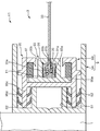
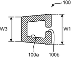
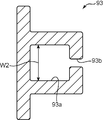
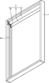
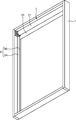
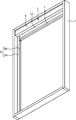
- FIG. 1 It is a schematic plan view which shows the screen apparatus which concerns on this embodiment. It is the II sectional view taken on the line shown in FIG. It is a schematic sectional drawing which shows only a rail member among the inner side guide rails which concern on this embodiment, Comprising: The state before the said rail member is accommodated in the 2nd accommodating part of a holding member is shown. It is a schematic sectional drawing which shows only a holding member among the inner side guide rails which concern on this embodiment. It is a figure which shows progress in the manufacturing process of the screen apparatus which concerns on this embodiment, Comprising: The state which attached the winding screen and the outer side guide rail with respect to a frame member is shown.
- the screen device according to the present invention may include any constituent member that is not shown in each drawing referred to in this specification.
- the screen device X1 is a winding screen device applied to a window frame in a house or the like.
- the screen device X1 includes a frame member 1, a winding screen 3, a front cover 5, a weight bar 7, and a guide rail 9.
- the screen device X1 may have a configuration in which a screen member 33 described later is wound up electrically, or may be configured in such a manner that the screen member 33 is manually wound up with a chain or the like.
- the screen device according to the present invention is also applied to systems other than the winding type.
- the screen device according to the present invention is applied not only to a window frame in a house, but also to a projector screen, for example.
- the frame member 1 is a member constituting the outer frame of the screen device X1.
- the frame member 1 has a rectangular shape in plan view.
- the rectangular area surrounded by the frame member 1 is an area opened and closed by a screen member 33 described later.
- the frame member 1 does not have to be rectangular in plan view, and can be appropriately changed according to the usage mode of the screen device X1. Further, the frame member 1 may not be provided. For example, a window frame in a house or the like may be used as the frame member 1.
- the winding screen 3 includes a winding shaft 31, a screen member 33, and a retaining member 35.
- the winding shaft 31 has a role of winding the screen member 33.
- the winding shaft 31 is a columnar member that extends in the short direction of the frame member 1.
- the winding shaft 31 is disposed along the upper frame of the frame member 1 in a region surrounded by the frame member 1. Further, the winding shaft 31 is attached to both side frames of the frame member 1 in a state in which the winding shaft 31 is rotatable in the circumferential direction of the winding shaft 31.
- the winding shaft 31 may be arranged along the lower frame of the frame member 1.
- the screen member 33 has a role of opening and closing a region surrounded by the frame member 1. An upper end portion of the screen member 33 is connected to the winding shaft 31. The screen member 33 is wound around the winding shaft 31 according to the rotation of the winding shaft 31, thereby opening a part or all of the region surrounded by the frame member 1. Further, the screen member 33 is sent out from the take-up shaft 31 according to the rotation of the take-up shaft 31, thereby closing a part or all of the region surrounded by the frame member 1.
- the retaining member 35 prevents the screen member 33 from coming off from the guide rail 9 described later. Further, the retaining member 35 guides the screen member 33 along the guide rail 9 so that it can move up and down.
- the retaining member 35 is attached to both side end portions 33 a of the screen member 33.
- the retaining member 35 covers the side end portion 33 a of the screen member 33 from both the front and back surfaces of the screen member 33, and extends along the longitudinal direction of the frame member 1.
- the retaining members 35 attached to the both side end portions 33 a of the screen member 33 are accommodated in the guide rails 9 attached to the both side frames of the frame member 1.
- the screen member 33 is supported by the guide rail 9 in the short direction of the frame member 1 and is movable up and down along the guide rail 9 in the longitudinal direction of the frame member 1.
- the retaining member 35 is wound around the winding shaft 31 together with the screen member 33 when the screen member 33 is wound according to the rotation of the winding shaft 31.
- the front cover 5 has a role of preventing the winding shaft 31 from being visually recognized by the user.
- the front cover 5 is disposed in front of the winding shaft 31, that is, on the user side so as to overlap the winding shaft 31 in plan view.
- the front cover 5 is fixed to the frame member 1 using, for example, a magnet sheet (not shown).
- the weight bar 7 has a role of applying an appropriate tension to the screen member 33 in the longitudinal direction of the frame member 1 in a state where the screen member 33 is fed from the winding shaft 31.
- the weight bar 7 extends along the short direction of the frame member 1 and is attached to the lower end of the screen member 33.
- the guide rail 9 has a role of guiding the vertical movement of the screen member 33.
- the guide rail 9 includes an outer guide rail 9A and an inner guide rail 9B.
- the outer guide rail 9A is a member that accommodates the inner guide rail 9B, and has a role of preventing the inner guide rail 9B from being visually recognized by the user.
- the outer guide rail 9 ⁇ / b> A is arranged along both side frames of the frame member 1 in a region surrounded by the frame member 1.
- the outer guide rail 9 ⁇ / b> A is a concave member extending along the longitudinal direction of the frame member 1.
- the bottom of the outer guide rail 9A is connected to the side frame of the frame member 1 via a screw (not shown).
- the recessed space in the outer guide rail 9A faces the first space S1 in which the screw head of the screw is accommodated and the first space S1 across the first space S1.
- the first space S1 and each second space S2 are partitioned from each other by a partition wall extending along the short direction of the frame member 1 from the bottom of the outer guide rail 9A.
- the inner guide rail 9B is a member accommodated in a recessed space in the outer guide rail 9A.
- the inner guide rail 9B has a role of accommodating the side end portion 33a of the screen member 33 and the retaining member 35 so that the screen member 33 can move up and down.
- the inner guide rail 9 ⁇ / b> B is arranged along the both side frames of the frame member 1 in the region surrounded by the frame member 1, similarly to the outer guide rail 9 ⁇ / b> A.
- the inner guide rail 9 ⁇ / b> B includes a rail member 91, a holding member 93, a fitting member 95, and an elastic body 97.
- the rail member 91 has a role of directly guiding the vertical movement of the screen member 33 while accommodating the side end portion 33a of the screen member 33 and the retaining member 35.
- the rail member 91 has a hollow shape, communicates the first accommodating portion 91a corresponding to the hollow portion, the first accommodating portion 91a and the outside of the rail member 91, and in the length direction of the rail member 91. It has the 1st slit 91b extended along.
- the side end 33a and the retaining member 35 of the screen member 33 are accommodated in the first accommodating portion 91a via the first slit 91b. In other words, the screen member 33 is inserted into the first accommodating portion 91a through the first slit 91b.
- the screen member 33 is located from the 1st accommodating part 91a to the exterior of the said 1st accommodating part 91a.
- the retaining member 35 is attached to the side end part 33a of the screen member 33 located in the 1st accommodating part 91a.
- the width of the first slit 91b is smaller than the thickness T1 of the retaining member 35. For this reason, it can suppress that the side edge part 33a of the screen member 33 to which the securing member 35 was attached remove
- the holding member 93 has a role of holding the rail member 91.
- the holding member 93 has a hollow shape, and includes a second housing portion 93 a corresponding to the hollow portion, and a second slit 93 b that communicates the second housing portion 93 a and the outside of the holding member 93.
- the second accommodating portion 93a accommodates the rail member 91.
- the second slit 93b extends along the length direction of the holding member 93 and communicates with the first slit 91b.
- the width of the second slit 93b is set larger than the width of the first slit 91b.
- the fitting member 95 has a role of fixing the inner guide rail 9B to the outer guide rail 9A when the inner guide rail 9B is accommodated in the recessed space in the outer guide rail 9A.
- the fitting member 95 has a hollow shape and includes a third housing portion 95a, a third slit 95b, a fitting portion 95c, and a plurality of protrusions 95b.
- the third accommodating portion 95 b corresponds to the hollow portion of the fitting member 95.
- the third slit 95b communicates the third housing portion 95a and the outside of the fitting member 95.
- the third slit 95 b extends along the length direction of the fitting member 95.
- the fitting portion 95c is fitted in the second space S2. Each protrusion 95d protrudes from the surface of the fitting portion 95c.
- the third accommodating portion 95a accommodates the holding member 93.
- the surface provided with the second slit 93b is exposed from the fitting member 95 in the third slit 95b.
- An elastic body 97 is interposed between the inner peripheral surface of the fitting member 95 and the outer peripheral surface of the holding member 93. Thereby, the space
- the fitting portion 95c extends from the surface of the fitting member 95 opposite to the surface provided with the third slit 95b toward the bottom portion of the outer guide rail 9A.
- Two fitting portions 95c are provided corresponding to the two second spaces S2, and are fitted in the second spaces S2.
- the plurality of protrusions 95d are softer than the fitting portions 95c.
- the plurality of protrusions 95d are elastically deformed by coming into contact with the inner peripheral surface of the outer guide rail 9A surrounding the second space S2 when the fitting portion 95c is fitted into the second space S2.
- the plurality of protrusions 95d apply a repulsive force to the inner peripheral surface of the outer guide rail 9A.
- the fitting part 95c and the some protrusion 95d are fixed in 2nd space S2. That is, in the screen device X1, the inner guide rail 9B is accommodated in the recessed space in the outer guide rail 9A by fitting the fitting portion 95c of the fitting member 95 in the inner guide rail 9B into the second space S2. .
- the rail member 91 is compressed and deformed in the width direction of the first slit 91b by the holding member 93.
- the width of the first slit 91b is kept smaller than the thickness T1 of the retaining member 35.
- the width W ⁇ b> 1 of the surface provided with the first slit 100 b of the rail member 100 that is the rail member 91 before being held by the holding member 93 is held.
- the width is set to be greater than the width W2 of the second housing portion 93a of the member 93.
- the first slit 100 b is provided in the rail member 100.
- the surface is compressed and deformed in the width direction of the first slit 100b. Accordingly, the width of the first slit 91 b of the rail member 91 held by the holding member 93 is smaller than the width of the first slit 100 b of the rail member 100 before being held by the holding member 93.
- the holding member 93 reduces the width of the first slit 100b of the rail member 100, whereby the first slit 91b of the rail member 91 is formed.
- the rail member 100 has a very small width in the manufacturing process of the screen device X1. Even if the first slit 100b is not formed, the retaining member 35 can be prevented from coming out of the first slit 91b.
- the rail member 100 since it is not necessary to form the first slit 100b having a very small width in the rail member 100 in the manufacturing process of the screen device X1, for example, when the rail member 100 is formed by extruding a resin material. The first slit 100b can be prevented from being blocked due to the small width. For this reason, the rail member 100 can be manufactured easily.
- the rail member 91 is housed in the second housing portion 93a of the holding member 93 and is compressed and deformed in the width direction of the first slit 91b in the second housing portion 93a. According to such a configuration, it is possible to prevent the rail member 91 from being detached from the holding member 93 while reducing the width of the first slit 91b in the second housing portion 93a.
- the holding member 93 does not need to have the 2nd accommodating part 93a and the 2nd slit 93b.
- the holding member 93 only needs to be configured to compress and deform at least the rail member 91 in the width direction of the first slit 91b.
- the width W3 of the surface of the rail member 100 opposite to the surface on which the first slit 100b is provided is equal to or smaller than the width W2 of the second housing portion 93a. According to such a configuration, when the rail member 100 is accommodated in the second accommodating portion 93a, the surface opposite to the surface provided with the first slit 100b is not compressed and deformed in the width direction of the first slit 100b. The accommodation can be easily performed.
- the rigidity of the holding member 93 is higher than the rigidity of the rail member 100. According to such a configuration, the rail member 100 can be reliably compressed and deformed by the holding member 93. In addition, the rigidity of the holding member 93 and the rail member 100 is appropriately adjusted depending on the material or thickness of each member.
- the screen device X1 described above can be manufactured reasonably and easily, for example, by a method including the following steps.
- a method for manufacturing the screen device X1 will be described in detail with reference to FIGS.
- a frame member 1 made of a metal material or a resin material is prepared.
- the frame member 1 is formed in a substantially rectangular shape in plan view.
- the winding screen 3 including the winding shaft 31, the screen member 33, and the retaining member 35 is prepared, and the winding screen 3 is attached to the frame member 1.
- the cloth-made screen member 33 is formed in a substantially rectangular shape having the same area as the area surrounded by the frame member 1.
- a retaining member 35 made of a resin material or the like is attached to both side end portions 33 a of the screen member 33, that is, both long sides of the screen member 33. More specifically, the tape-shaped retaining member 35 is bent, and the retaining member 35 is bonded to the both side end portions 33 a so as to sandwich both side end portions 33 a of the screen member 33 from both sides of the screen member 33. .
- the upper end part of the screen member 33 ie, one short side of the screen member 33, is attached along the axial direction of the said winding shaft 31 with respect to the winding shaft 31 formed in the column shape.
- the screen member 33 and the retaining member 35 are wound around the winding shaft 31 in the circumferential direction of the winding shaft 31.
- the winding screen 3 prepared in this way is arranged along the upper frame of the frame member 1 in a region surrounded by the frame member 1.
- the winding shaft 31 in the winding screen 3 is fixed to the both side frames of the frame member 1 in a state in which the winding shaft 31 can rotate in the circumferential direction of the winding shaft 31.
- an outer guide rail 9A made of a metal material or a resin material is prepared, and the outer guide rail 9A is attached to the frame member 1.
- the outer guide rail 9A is a concave member extending along one direction.
- the outer guide rail 9A is formed with two partition walls extending along the direction orthogonal to the one direction from the bottom of the outer guide rail 9A in the recessed space of the outer guide rail 9A.
- the recessed space in the outer guide rail 9A includes a first space S1 and two second spaces S2 partitioned by the two partition walls.
- the outer guide rail 9 ⁇ / b> A is disposed along both side frames of the frame member 1 in a region surrounded by the frame member 1.
- the bottom part of 9 A of outer side guide rails is fixed to the both-sides frame of the frame member 1 via a screw etc., and the screw head of the said screw is arrange
- the inner guide rail 9B including the rail member 91, the holding member 93, the fitting member 95, and the elastic body 97 is prepared.
- the rail member 100 shown in FIG. 3 is prepared, and the holding member 93 shown in FIG. 4 is prepared.
- the rail member 100 is a member that becomes the rail member 91 by being held by the holding member 93.
- the rail member 100 is formed into a hollow shape extending along one direction by extruding a resin material.
- the rail member 100 is formed with a first housing portion 100a corresponding to a hollow portion of the rail member 100 and a first slit 91b that communicates with the first housing portion 100a and extends along the one direction.
- the holding member 93 is formed into a hollow shape extending along one direction by extruding a resin material.
- the holding member 93 is formed with a second housing portion 93a corresponding to a hollow portion of the holding member 93 and a second slit 93b that communicates with the second housing portion 93a and extends along the one direction.
- the width W2 of the second housing portion 93a is smaller than the width W1 of the surface of the rail member 100 where the first slit 100b is formed, and the surface of the rail member 100 where the first slit 100b is formed. It is set to be equal to or greater than the width W3 of the opposite surface.
- the rail member 100 is inserted into the second housing portion 93 a of the holding member 93 along the length direction of the holding member 93.
- the inserted rail member 100 is accommodated in the second accommodating portion 93a, and the width of the first slit 100b is reduced by compressing and deforming the surface on which the first slit 100b is formed, thereby the rail member. 91.
- the width of the first slit 91 b of the rail member 91 is set to be smaller than the thickness T ⁇ b> 1 of the retaining member 35.
- the fitting member 95 is prepared.
- the fitting member 95 is formed into a hollow shape extending along one direction by extruding a resin material.
- the fitting member 95 is formed with a third housing portion 95a corresponding to a hollow portion of the fitting member 95 and a third slit 95b that communicates with the third housing portion 95a and extends along the one direction.
- the fitting member 95 has fitting portions 95c that are located at both ends in the width direction on the surface opposite to the surface on which the third slit 95b is formed and extend in a direction away from the third housing portion 95a. It is formed.
- the fitting member 95 is formed with a plurality of protrusions 95d that protrude from the fitting portion 95c.
- the plurality of protrusions 95d are formed softer than other portions of the fitting member 95. For this reason, so-called two-color molding in which different materials are combined and molded integrally is applied to the extrusion molding of the fitting member 95.
- the rail member 91 and the holding member 93 are inserted into the third housing portion 95 a of the fitting member 95 along the length direction of the fitting member 95.
- the elastic body 97 is interposed between the outer peripheral surface of the holding member 93 and the inner peripheral surface of the fitting member 95, and the relative position of the holding member 93 with respect to the fitting member 95 is set by the elastic body 97.
- the inner guide rail 9B prepared in this way is disposed along the length direction of the outer guide rail 9A, and is accommodated in a recessed space in the outer guide rail 9A.
- the fitting portion 95c of the fitting member 95 in the inner guide rail 9B is inserted into the second space S2 in the recessed space in the outer guide rail 9A.
- the plurality of protrusions 95d protruding from the fitting portion 95c are elastically deformed by coming into contact with the inner peripheral surface of the outer guide rail 9A, and a repulsive force is applied to the inner peripheral surface. Accordingly, the fitting portion 95c and the plurality of protrusions 95d are fixed in the second space S2, and the inner guide rail 9B is accommodated in the recessed space in the outer guide rail 9A.
- the side end 33 a of the screen member 33 and the retaining member 35 attached to the side end 33 a are inserted into the first accommodating portion 91 a of the rail member 91 along the length direction of the rail member 91. . At this time, a portion of the screen member 33 that is continuous with the side end portion 33a in the short side direction of the screen member 33 is inserted into the first slit 91b and the second slit 93b.
- a front cover 5 made of a metal material or the like is prepared, and the front cover 5 is attached to the frame member 1.
- the front cover 5 is large enough to prevent the winding screen 3 from being visually recognized by the user when the screen member 33 and the retaining member 35 are completely wound around the winding shaft 31. It is formed.
- the front cover 5 is disposed in front of the winding shaft 31 and is fixed to the frame member 1 via a magnet sheet (not shown).
- the weight bar 7 is prepared, and the weight bar 7 is attached to the screen member 33.
- the weight bar 7 is a member extending along one direction, and is formed with a weight that can apply an appropriate tension to the screen member 33.
- the weight bar 7 is disposed along the lower end of the screen member 33, that is, along the short side of the screen member 33 that is opposite to the short side attached to the winding shaft 31. Attached to the lower end.
- both ends of the weight bar 7 are disposed in a recessed space in the outer guide rail 9A. Thereby, the vertical movement of the weight bar 7 is guided to the outer guide rail 9A.
- the weight bar 7 may be attached to the lower end of the screen member 33 when the take-up screen 3 is attached to the frame member 1 in the step of attaching the take-up screen 3 and the outer guide rail 9A.
- the manufacturing process is simplified by forming the rail member 100 in a specific shape.
- the width W1 of the surface of the rail member 100 where the first slit 100b is provided is set larger than the width W2 of the second housing portion 93a, and the rail
- the width W3 of the surface of the member 100 opposite to the surface on which the first slit 100b is provided is set to be equal to or smaller than the width W2 of the second housing portion 93a. Therefore, the surface of the rail member 100 on which the first slit 100b is provided is pressed against the inner peripheral surface of the holding member 93 when the rail member 100 is accommodated in the second accommodating portion 93a.
- the rail member 100 is accommodated in the second accommodating portion 93a and the width of the first slit 100b is accommodated in the step of accommodating the rail member 100 in the second accommodating portion 93a. Reduction is achieved at the same time.
- the surface of the rail member 100 opposite to the surface on which the first slit 100b is provided does not apply a repulsive force to the inner peripheral surface of the holding member 93 in the width direction of the second housing portion 93a. 2
- the rail member 100 can be easily accommodated in the accommodating portion 93a. For this reason, the manufacturing process of the screen apparatus X1 is simplified.
- the rail member 100 can be easily formed. Specifically, in the case where the rail member 100 is formed by extruding a resin material as in the manufacturing method of the screen device X1 described above, if the width of the first slit 100b is to be formed extremely narrow, the extruding molding is performed. In the process, the first slit 100b may be blocked, and it becomes difficult to form the first slit 100b in the rail member 100. Therefore, in the method of manufacturing the screen device X1, the width of the first slit 100b can be reduced by accommodating the rail member 100 in the second accommodating portion 93a, so that the first slit 100b of the rail member 100 is extremely small. There is no need to form it narrowly, so that the rail member 100 can be easily formed.
- the screen device includes a screen member, a retaining member attached to a side end portion of the screen member, a housing portion, and a slit that communicates with the housing portion.
- the rail member that holds the screen member in a movable state along the length direction of the slit, with the end portion and the retaining member being accommodated in the accommodating portion via the slit, and the rail member Holding the holding member, and the rail member is compressed and deformed in the width direction of the slit by the holding member, and the width of the slit of the rail member subjected to the compression deformation is the thickness of the retaining member. Smaller than.
- the holding member compresses and deforms the rail member, whereby the width of the slit can be reduced. Thereby, it can suppress that a locking member slips out of an accommodating part via a slit.
- the rail member having the slit is compressed and deformed in the width direction of the slit by being held by the holding member. For this reason, the width of the slit in the rail member held by the holding member is smaller than the width of the slit in the rail member before being held by the holding member. That is, in the above screen device, after the slit is formed in the rail member in the manufacturing process of the screen device, the width of the slit is reduced by the holding member.
- the width of the slit in the rail member held by the holding member is set smaller than the thickness of the retaining member.
- the width of the slit can be reduced by the holding member without forming a very small slit in the rail member in the manufacturing process of the screen device. For this reason, it is possible to easily mold the rail member and to prevent the retaining member from coming out of the accommodating portion through the slit.
- the holding member houses the rail member and the rail member is the width of the first slit. It is preferable to have a second accommodating portion that is compressed and deformed in a direction, and a second slit that is communicated with the second accommodating portion and the first slit and is provided along the length direction of the first slit.
- the screen device having such a configuration by accommodating the rail member in the second accommodating portion, it is possible to reduce the width of the first slit and to prevent the rail member from being detached from the holding member.
- the manufacturing method of the screen device includes a step of forming a rail member having a first housing portion and a first slit communicating with the first housing portion by extrusion molding, and is secured to a side end portion of the screen member. While attaching a member, the screen member is accommodated in the rail member by accommodating the side end portion of the screen member and the retaining member in the first accommodating portion via the first slit.
- the width of the surface of the material on which the first slit is provided is set to be larger than the width of the second accommodating portion, and the surface of the rail member opposite to the surface on which the first slit is provided.
- the surface of the rail member on which the first slit is provided is the surface of the first slit in the second housing portion.
- the width of the first slit can be easily reduced in the step of accommodating the rail member in the second accommodating portion.
- the manufacturing process is simplified. Specifically, in the method of manufacturing the screen device, in the step of forming the rail member, the width of the surface of the rail member on which the first slit is provided is set larger than the width of the second housing portion. At the same time, the width of the surface of the rail member opposite to the surface provided with the first slit is set to be equal to or smaller than the width of the second housing portion.
- the surface of the rail member on which the first slit is provided is compressed and deformed in the width direction of the first slit in the second housing portion. That is, in the method for manufacturing the screen device, in the step of storing the rail member in the second storage portion, the rail member is stored in the second storage portion and the width of the first slit is reduced at the same time. The process is simplified. Moreover, since it is not necessary to form the width
Landscapes
- Engineering & Computer Science (AREA)
- Structural Engineering (AREA)
- Architecture (AREA)
- Civil Engineering (AREA)
- Life Sciences & Earth Sciences (AREA)
- Insects & Arthropods (AREA)
- Pest Control & Pesticides (AREA)
- Operating, Guiding And Securing Of Roll- Type Closing Members (AREA)
- Overhead Projectors And Projection Screens (AREA)
- Extrusion Moulding Of Plastics Or The Like (AREA)
Abstract
スクリーン部材33と、スクリーン部材33の側端部33aに取り付けられる抜止部材35と、第1収容部91a、および第1収容部91aに連通した第1スリット91bを有しており、スクリーン部材33の側端部33aおよび抜止部材35が第1スリット91bを介して第1収容部91aに収容されることにより、スクリーン部材33を第1スリット91bの長さ方向に沿って移動可能な状態に保持するレール部材91と、レール部材91を保持する保持部材93と、を備え、レール部材91は、保持部材93によって第1スリット91bの幅方向に圧縮変形されており、当該圧縮変形されたレール部材91の第1スリット91bの幅は、抜止部材35の厚みT1よりも小さい。
Description
本発明は、スクリーン装置およびその製造方法に関する。
従来、スクリーン装置としては、例えば特許文献1に記載された巻取式スクリーン装置が知られている。この巻取式スクリーン装置は、スクリーンとしてのネットと、当該ネットが巻付けられた巻取軸と、スクリーンの側端部に取り付けられた抜止部材(係止部材)と、中空状のガイドレールと、を備える。スクリーンの側端部に取り付けられた抜止部材は、ガイドレールに設けられたスリットを介して当該ガイドレール内に挿入されており、巻取軸の巻取方向に移動可能な状態である。この巻取式スクリーン装置では、ガイドレール内に位置する抜止部材の厚みがスリットの幅よりも大きく設定されており、これによりネットとガイドレールとが係合している。そして、ガイドレール内に位置する抜止部材は、巻取軸においてネットと同時に巻き取られる。
ところで、上記の巻取式スクリーン装置において、例えば、巻取軸におけるネットおよび抜止部材の巻取径を小さくするためには、抜止部材の厚みを小さく設定する必要がある。しかしながら、抜止部材の厚みを小さく設定する場合、当該抜止部材がスリットを介してガイドレール外へと抜け出てしまう可能性がある。このような課題を解決するためには、抜止部材の厚みに対応してスリットの幅を極めて小さく設定する必要がある。しかしながら、巻取式スクリーン装置の製造工程において、ガイドレールのスリットを極めて小さな幅で形成することは困難である。
本発明の目的は、上述の課題を解決したスクリーン装置およびその製造方法を提供することである。
本発明の一局面に従うスクリーン装置は、スクリーン部材と、前記スクリーン部材の側端部に取り付けられた抜止部材と、収容部、および前記収容部に連通したスリットを有しており、前記スクリーン部材の側端部および前記抜止部材が前記スリットを介して前記収容部内に収容されることで、前記スクリーン部材を前記スリットの長さ方向に沿って移動可能な状態に保持したレール部材と、前記レール部材を保持した保持部材と、を備え、前記レール部材は、前記保持部材によって前記スリットの幅方向に圧縮変形されており、当該圧縮変形された前記レール部材の前記スリットの幅は、前記抜止部材の厚みよりも小さいことを特徴とする。
本発明の一局面に従うスクリーン装置の製造方法は、押出成形によって、第1収容部および前記第1収容部に連通する第1スリットを有するレール部材を成形する工程と、スクリーン部材の側端部に抜止部材を取り付けるとともに、前記スクリーン部材の前記側端部および前記抜止部材を、前記第1スリットを介して前記第1収容部に収容することにより、前記レール部材に前記スクリーン部材を前記第1スリットの長さ方向に沿って移動可能な状態に保持させる工程と、第2収容部および前記第2収容部に連通する第2スリットを有する保持部材を準備する工程と、前記第1スリットと前記第2スリットとが連通するように、前記第2収容部に前記レール部材を収容する工程と、を備え、前記レール部材を成形する工程において、前記レール部材のうち前記第1スリットが設けられた面の幅は前記第2収容部の幅よりも大きく設定されるとともに、前記レール部材のうち前記第1スリットが設けられた面とは反対側の面の幅は前記第2収容部の幅以下に設定され、前記レール部材を収容する工程において、前記レール部材のうち前記第1スリットが設けられた面が前記第2収容部において前記第1スリットの幅方向に圧縮変形されることにより、前記第1スリットの幅が縮小し、これにより前記第1スリットの幅が前記抜止部材の厚みよりも小さく設定されることを特徴とする。
以下、本発明の一実施形態について、図面を参照しながら説明する。但し、以下で参照する各図は、説明の便宜上、本発明の一実施形態の構成部材のうち、本発明を説明するために必要な主要部材を簡略化して示したものである。したがって、本発明に係るスクリーン装置は、本明細書が参照する各図に示されていない任意の構成部材を備え得る。
図1および図2に示すように、スクリーン装置X1は、住宅等における窓枠に適用される巻取式のスクリーン装置である。スクリーン装置X1は、枠部材1、巻取スクリーン3、前面カバー5、ウェイトバー7、およびガイドレール9を備える。スクリーン装置X1は、例えば、後述するスクリーン部材33を電動で巻き取る構成であってもよいし、当該スクリーン部材33をチェーン等によって手動で巻き取る構成であってもよい。なお、本発明に係るスクリーン装置は、巻取式以外の方式にも適用される。また、本発明に係るスクリーン装置は、住宅等における窓枠のみならず、例えば、プロジェクタスクリーン等にも適用される。
枠部材1は、スクリーン装置X1の外枠を構成する部材である。本実施形態では、枠部材1は、平面視して矩形状である。ここで、当該枠部材1によって取り囲まれる矩形状の領域は、後述するスクリーン部材33によって開閉される領域となる。なお、枠部材1は、平面視して矩形状でなくともよく、スクリーン装置X1の使用態様に応じて適宜変更することができる。また、枠部材1はなくともよく、例えば、住宅等における窓枠を枠部材1として利用してもよい。
巻取スクリーン3は、巻取軸31、スクリーン部材33、および抜止部材35を備える。
巻取軸31は、スクリーン部材33を巻き取る役割を有する。巻取軸31は、枠部材1の短手方向に延びる円柱形状の部材である。巻取軸31は、枠部材1によって取り囲まれる領域において、当該枠部材1の上枠に沿って配置されている。また、巻取軸31は、当該巻取軸31の周方向に回動可能な状態で、枠部材1の両側枠に取り付けられている。なお、巻取軸31は、枠部材1の下枠に沿って配置されていてもよい。
スクリーン部材33は、枠部材1によって取り囲まれる領域を開閉する役割を有する。スクリーン部材33の上端部は、巻取軸31に接続されている。そして、スクリーン部材33は、巻取軸31の回動に応じて当該巻取軸31に巻き取られることにより、枠部材1によって取り囲まれる領域の一部または全部を開放する。また、スクリーン部材33は、巻取軸31の回動に応じて当該巻取軸31から送り出されることにより、枠部材1によって取り囲まれる領域の一部または全部を閉鎖する。
抜止部材35は、スクリーン部材33が後述するガイドレール9から外れることを抑止する。また、抜止部材35は、ガイドレール9に沿ってスクリーン部材33が上下動可能なようにガイドする。抜止部材35は、スクリーン部材33の両側端部33aに取り付けられている。抜止部材35は、スクリーン部材33の側端部33aを当該スクリーン部材33の表裏両面から覆っており、枠部材1の長手方向に沿って延びている。そして、スクリーン部材33の両側端部33aに取り付けられた抜止部材35は、枠部材1の両側枠に取り付けられたガイドレール9内に収容されている。これにより、スクリーン部材33は、枠部材1の短手方向においてガイドレール9に支持されるとともに、枠部材1の長手方向においてガイドレール9に沿って上下動可能な状態にある。そして、抜止部材35は、巻取軸31の回動に応じてスクリーン部材33が巻き取られる際に、当該スクリーン部材33とともに巻取軸31に巻き取られる。
前面カバー5は、巻取軸31が使用者から視認されることを抑止する役割を有する。前面カバー5は、平面視して巻取軸31と重なるように、当該巻取軸31の前方、すなわち使用者側に配置されている。前面カバー5は、例えば、図示しないマグネットシート等を用いて枠部材1に固定されている。
ウェイトバー7は、巻取軸31からスクリーン部材33が送り出された状態において、当該スクリーン部材33に対して枠部材1の長手方向に適度な張力を与える役割を有する。ウェイトバー7は、枠部材1の短手方向に沿って延びており、スクリーン部材33の下端部に取り付けられている。
ガイドレール9は、スクリーン部材33の上下動をガイドする役割を有する。ガイドレール9は、外側ガイドレール9Aおよび内側ガイドレール9Bを備える。
外側ガイドレール9Aは、内側ガイドレール9Bを収容する部材であって、当該内側ガイドレール9Bが使用者から視認されることを抑止する役割を有する。外側ガイドレール9Aは、枠部材1によって取り囲まれる領域において、当該枠部材1の両側枠に沿って配置されている。外側ガイドレール9Aは、枠部材1の長手方向に沿って延びる凹型の部材である。外側ガイドレール9Aの底部は、図示しないネジを介して枠部材1の側枠に接続される。本実施形態では、外側ガイドレール9Aにおける凹んだ空間は、図2に示すように、前記ネジのネジ頭が収容される第1空間S1と、当該第1空間S1を挟んで互いに対向しており且つ後述する嵌込部材95の嵌込部95cが嵌め込まれる2つの第2空間S2と、を含む。第1空間S1と各第2空間S2とは、外側ガイドレール9Aの底部から枠部材1の短手方向に沿って延びる区画壁によって互いに区画されている。
内側ガイドレール9Bは、外側ガイドレール9Aにおける凹んだ空間に収容される部材である。内側ガイドレール9Bは、スクリーン部材33が上下動可能なように当該スクリーン部材33の側端部33aおよび抜止部材35を収容する役割を有する。内側ガイドレール9Bは、外側ガイドレール9Aと同様に、枠部材1によって取り囲まれる領域において、当該枠部材1の両側枠に沿って配置されている。また、内側ガイドレール9Bは、レール部材91、保持部材93、嵌込部材95、および弾性体97を備える。
レール部材91は、スクリーン部材33の側端部33aおよび抜止部材35を収容しつつ、スクリーン部材33の上下動を直接ガイドする役割を有する。レール部材91は、中空形状をなしており、当該中空部分に対応する第1収容部91a、および当該第1収容部91aとレール部材91の外部とを連通するとともにレール部材91の長さ方向に沿って延びる第1スリット91bを有する。スクリーン部材33の側端部33aおよび抜止部材35は、第1スリット91bを介して第1収容部91aに収容される。換言すれば、スクリーン部材33は、第1スリット91bを介して第1収容部91aに挿入されている。これにより、スクリーン部材33は、第1収容部91aから当該第1収容部91aの外部に亘って位置している。そして、第1収容部91aに位置するスクリーン部材33の側端部33aには、抜止部材35が取り付けられている。
ここで、第1スリット91bの幅は、抜止部材35の厚みT1よりも小さい。このため、抜止部材35が取り付けられたスクリーン部材33の側端部33aが、第1スリット91bを介してレール部材91から外れてしまうことを抑止できる。また、第1収容部91aの幅は、抜止部材35の厚みT1よりも大きい。このため、枠部材1の短手方向においてスクリーン部材33が支持された状態で、枠部材1の長手方向において抜止部材35が第1収容部91a内を移動可能である。
保持部材93は、レール部材91を保持する役割を有する。保持部材93は、中空形状をなしており、当該中空部分に対応する第2収容部93a、および当該第2収容部93aと保持部材93の外部とを連通する第2スリット93bを有する。第2収容部93aは、レール部材91を収容している。これにより、保持部材93は、レール部材91を保持している。また、第2スリット93bは、保持部材93の長さ方向に沿って延びており、第1スリット91bと連通している。この第2スリット93bの幅は、第1スリット91bの幅よりも大きく設定される。
嵌込部材95は、内側ガイドレール9Bを外側ガイドレール9Aにおける凹んだ空間に収容する際に、当該内側ガイドレール9Bを外側ガイドレール9Aに固定する役割を有する。嵌込部材95は、中空形状をなしており、第3収容部95a、第3スリット95b、嵌込部95c、および複数の突起95bを有する。第3収容部95bは、嵌込部材95の中空部分に対応している。第3スリット95bは、第3収容部95aと嵌込部材95の外部とを連通している。第3スリット95bは、嵌込部材95の長さ方向に沿って延びている。嵌込部95cは、前記第2空間S2に嵌め込まれている。各突起95dは、嵌込部95cの表面から突出している。
第3収容部95aは、保持部材93を収容している。また、第3収容部95aに収容された保持部材93のうち、第2スリット93bが設けられた面は、第3スリット95bにおいて嵌込部材95から露出している。なお、嵌込部材95の内周面と保持部材93の外周面との間には、弾性体97が介在している。これにより、枠部材1の両側枠に沿って配置された保持部材93同士の間隔が調整される。当該間隔は、スクリーン部材33に対して枠部材1の短手方向に適度な張力を与えることができる間隔に設定される。
嵌込部95cは、嵌込部材95のうち第3スリット95bが設けられた面とは反対側の面から、外側ガイドレール9Aの前記底部に向かって延びている。また、嵌込部95cは、2つの第2空間S2に対応して2つ設けられており、各第2空間S2に嵌め込まれている。ここで、複数の突起95dは、嵌込部95cに比して軟質である。複数の突起95dは、嵌込部95cが第2空間S2に嵌め込まれた際に、当該第2空間S2を取り囲む外側ガイドレール9Aの内周面に当接することで弾性変形する。そして、複数の突起95dは、外側ガイドレール9Aの内周面に対して反発力を加える。これにより、嵌込部95cおよび複数の突起95dは、第2空間S2において固定される。すなわち、スクリーン装置X1では、内側ガイドレール9Bにおける嵌込部材95の嵌込部95cが第2空間S2に嵌め込まれることにより、当該内側ガイドレール9Bが外側ガイドレール9Aにおける凹んだ空間に収容される。
ところで、スクリーン装置X1では、レール部材91は、保持部材93によって第1スリット91bの幅方向に圧縮変形されている。これにより、当該第1スリット91bの幅が抜止部材35の厚みT1よりも小さい状態を保っている。具体的には、図3および図4に示すように、保持部材93に保持される以前のレール部材91であるレール部材100のうち、第1スリット100bが設けられた面の幅W1は、保持部材93の第2収容部93aの幅W2よりも大きく設定される。このため、保持部材93によってレール部材100が保持された場合、すなわち保持部材93の第2収容部93aにレール部材100が収容された場合に、レール部材100のうち第1スリット100bが設けられた面が当該第1スリット100bの幅方向に圧縮変形する。これにより、保持部材93に保持されたレール部材91の第1スリット91bの幅は、保持部材93に保持される以前のレール部材100の第1スリット100bの幅よりも小さくなる。
このように、スクリーン装置X1では、保持部材93がレール部材100の第1スリット100bの幅を小さくすることにより、レール部材91の第1スリット91bが形成される。このため、例えば巻取軸31における抜止部材35の巻取径を小さくする目的で当該抜止部材35の厚みT1を薄く設定した場合に、スクリーン装置X1の製造工程においてレール部材100に極めて小さな幅の第1スリット100bを形成しなくとも、第1スリット91bから抜止部材35が抜け出すことを抑止できる。また、上記のとおり、スクリーン装置X1の製造工程においてレール部材100に極めて小さな幅の第1スリット100bを形成しなくともよいため、例えば樹脂材料を押出成形することによってレール部材100を成形する場合に、当該幅の小ささに起因して第1スリット100bが塞がってしまうことを抑止できる。このため、レール部材100を容易に製造することができる。
なお、本実施形態では、レール部材91は、保持部材93の第2収容部93aに収容されているとともに、当該第2収容部93aにおいて第1スリット91bの幅方向に圧縮変形されている。このような構成によれば、第2収容部93aにおいて、第1スリット91bの幅を小さくしつつ、レール部材91が保持部材93から外れることを抑止できる。なお、保持部材93は、第2収容部93aおよび第2スリット93bを有していなくともよい。保持部材93は、少なくともレール部材91を第1スリット91bの幅方向に圧縮変形するように構成されていればよい。
また、本実施形態では、レール部材100のうち第1スリット100bが設けられた面とは反対側の面の幅W3は、第2収容部93aの幅W2以下である。このような構成によれば、レール部材100を第2収容部93aに収容する際に、第1スリット100bが設けられた面の反対側の面が第1スリット100bの幅方向に圧縮変形されないので、当該収容を容易に行うことができる。
また、本実施形態では、保持部材93の剛性は、レール部材100の剛性に比して高い。このような構成によれば、保持部材93によってレール部材100を確実に圧縮変形させることができる。なお、保持部材93およびレール部材100の剛性は、それぞれの部材の材質あるいは厚み等によって適宜調整される。
以上説明したスクリーン装置X1は、例えば以下の工程を含む方法により、合理的かつ容易に製造されることが可能である。以下では、図5~図7を参照しつつ、スクリーン装置X1の製造方法について詳述する。
1)巻取スクリーン3および外側ガイドレール9Aの取付け工程
まず、図5を参照しつつ、巻取スクリーン3および外側ガイドレール9Aの取付け工程について説明する。
まず、図5を参照しつつ、巻取スクリーン3および外側ガイドレール9Aの取付け工程について説明する。
この工程では、まず、金属材料あるいは樹脂材料等からなる枠部材1が準備される。当該枠部材1は、平面視して略矩形状に形成される。
次に、巻取軸31、スクリーン部材33、および抜止部材35を備えた巻取スクリーン3が準備され、当該巻取スクリーン3が枠部材1に取り付けられる。具体的には、布製等のスクリーン部材33が、枠部材1が取り囲む領域と同程度の面積を有する略矩形状に形成される。そして、スクリーン部材33の両側端部33a、すなわちスクリーン部材33の両長辺に対して、樹脂材料等からなる抜止部材35が取り付けられる。より具体的には、テープ状の抜止部材35が折り曲げられ、当該抜止部材35がスクリーン部材33の両側端部33aを当該スクリーン部材33の両面から挟み込むようにして当該両側端部33aに接着される。そして、スクリーン部材33の上端部、すなわちスクリーン部材33の一方の短辺は、円柱形状に形成された巻取軸31に対して当該巻取軸31の軸方向に沿って取り付けられる。これにより、スクリーン部材33および抜止部材35は、巻取軸31に対して当該巻取軸31の周方向に巻き取られる。このようにして準備された巻取スクリーン3は、枠部材1によって取り囲まれる領域において、枠部材1の上枠に沿って配置される。そして、巻取スクリーン3における巻取軸31は、当該巻取軸31の周方向に回動可能な状態で、枠部材1の両側枠に固定される。
次に、金属材料あるいは樹脂材料等からなる外側ガイドレール9Aが準備され、当該外側ガイドレール9Aが枠部材1に取り付けられる。具体的には、外側ガイドレール9Aは、一方方向に沿って延びる凹型の部材である。外側ガイドレール9Aには、当該外側ガイドレール9Aにおける凹んだ空間内において、当該外側ガイドレール9Aの底部から前記一方方向と直交する方向に沿って延びる2つの区画壁が形成される。これにより、外側ガイドレール9Aにおける凹んだ空間は、2つの前記区画壁によって区画された第1空間S1および2つの第2空間S2を含む。この外側ガイドレール9Aは、枠部材1に取り囲まれる領域において、当該枠部材1の両側枠に沿って配置される。そして、外側ガイドレール9Aの底部は、ネジ等を介して枠部材1の両側枠に固定され、当該ネジのネジ頭が第1空間S1に配置される。
2)内側ガイドレール9Bの嵌め込み工程
次に、図6を参照しつつ、内側ガイドレール9Bの嵌め込み工程について説明する。
次に、図6を参照しつつ、内側ガイドレール9Bの嵌め込み工程について説明する。
この工程では、まず、レール部材91、保持部材93、嵌込部材95、および弾性体97を備えた内側ガイドレール9Bが準備される。
具体的には、まず、図3に示すレール部材100が準備されるとともに、図4に示す保持部材93が準備される。レール部材100は、保持部材93に保持されることによって、レール部材91となる部材である。レール部材100は、樹脂材料を押出成形することによって、一方方向に沿って延びる中空形状に成形される。このレール部材100には、当該レール部材100の中空部分にあたる第1収容部100a、および当該第1収容部100aに連通するとともに前記一方方向に沿って延びる第1スリット91bが形成される。また、保持部材93は、樹脂材料を押出成形することによって、一方方向に沿って延びる中空形状に成形される。この保持部材93には、当該保持部材93の中空部分にあたる第2収容部93a、および当該第2収容部93aに連通するとともに前記一方方向に沿って延びる第2スリット93bが形成される。ここで、第2収容部93aの幅W2は、レール部材100のうち第1スリット100bが形成された面の幅W1よりも小さく、且つレール部材100のうち第1スリット100bが形成された面と反対側の面の幅W3以上となるよう設定される。そして、レール部材100は、保持部材93の長さ方向に沿って当該保持部材93の第2収容部93a内へ挿入される。当該挿入されたレール部材100は、第2収容部93aに収容されるとともに、第1スリット100bの形成された面が圧縮変形することで当該第1スリット100bの幅が縮小し、これによりレール部材91となる。このとき、レール部材91の第1スリット91bの幅は、抜止部材35の厚みT1よりも小さく設定される。
次に、嵌込部材95が準備される。嵌込部材95は、樹脂材料を押出成形することによって、一方方向に沿って延びる中空形状に成形される。この嵌込部材95には、当該嵌込部材95の中空部分にあたる第3収容部95a、および当該第3収容部95aに連通するとともに前記一方方向に沿って延びる第3スリット95bが形成される。また、嵌込部材95には、第3スリット95bが形成された面とは反対側の面における幅方向両端に位置しており、且つ第3収容部95aから遠ざかる方向に延びる嵌込部95cが形成される。さらに、嵌込部材95には、嵌込部95cから突出する複数の突起95dが形成される。この複数の突起95dは、嵌込部材95における他の部位に比して軟質に形成される。このため、嵌込部材95の押出成形には、異材質同士を組み合わせて一体に成形するいわゆる2色成形が適用される。そして、レール部材91および保持部材93は、嵌込部材95の長さ方向に沿って当該嵌込部材95の第3収容部95a内へ挿入される。この際、保持部材93の外周面と嵌込部材95の内周面との間に弾性体97が介在され、当該弾性体97によって嵌込部材95に対する保持部材93の相対位置が設定される。
このようにして準備された内側ガイドレール9Bは、外側ガイドレール9Aの長さ方向に沿って配置され、当該外側ガイドレール9Aにおける凹んだ空間に収容される。具体的には、内側ガイドレール9Bにおける嵌込部材95の嵌込部95cは、外側ガイドレール9Aにおける凹んだ空間内の第2空間S2に挿入される。このとき、嵌込部95cから突出した複数の突起95dは、外側ガイドレール9Aの内周面に当接することで弾性変形し、当該内周面に対して反発力が加えられる。これにより、嵌込部95cおよび複数の突起95dが第2空間S2において固定され、内側ガイドレール9Bが外側ガイドレール9Aにおける凹んだ空間に収容される。
そして、スクリーン部材33の側端部33aおよび当該側端部33aに取り付けられた抜止部材35は、レール部材91の長さ方向に沿って当該レール部材91の第1収容部91a内に挿入される。このとき、スクリーン部材33のうち当該スクリーン部材33の短辺方向において側端部33aに連続する部位は、第1スリット91bおよび第2スリット93bに挿入されることになる。
3)前面カバー5およびウェイトバー7の取付け工程
次に、図7を参照しつつ、前面カバー5およびウェイトバー7の取付け工程について説明する。
次に、図7を参照しつつ、前面カバー5およびウェイトバー7の取付け工程について説明する。
この工程では、まず、金属材料等からなる前面カバー5が準備され、当該前面カバー5が枠部材1に取り付けられる。具体的には、前面カバー5は、スクリーン部材33および抜止部材35が巻取軸31に完全に巻き取られた状態における巻取スクリーン3が使用者から視認されるのを防ぐ程度の大きさで形成される。そして、前面カバー5は、巻取軸31の前方に配置されるとともに、図示しないマグネットシート等を介して枠部材1に固定される。
次に、ウェイトバー7が準備され、当該ウェイトバー7がスクリーン部材33に取り付けられる。具体的には、ウェイトバー7は、一方方向に沿って延びる部材であって、スクリーン部材33に適度な張力を加えることができる程度の重さで形成される。ウェイトバー7は、図7に示すように、スクリーン部材33の下端部、すなわちスクリーン部材33のうち巻取軸31に取り付けられた短辺の反対側に位置する短辺に沿って配置され、当該下端部に取り付けられる。そして、ウェイトバー7の両端は、外側ガイドレール9Aにおける凹んだ空間内に配置される。これにより、ウェイトバー7の上下動が外側ガイドレール9Aにガイドされる。なお、ウェイトバー7は、上記の巻取スクリーン3および外側ガイドレール9Aの取付け工程において、巻取スクリーン3が枠部材1に取り付けられる際に、スクリーン部材33の下端部に取り付けられてもよい。
以上のスクリーン装置X1の製造方法によれば、レール部材100を特定の形状で成形することによって、製造工程が簡略化される。具体的には、上記のスクリーン装置X1の製造方法では、レール部材100のうち第1スリット100bが設けられた面の幅W1が第2収容部93aの幅W2よりも大きく設定されるとともに、レール部材100のうち第1スリット100bが設けられた面とは反対側の面の幅W3が第2収容部93aの幅W2以下に設定される。このため、レール部材100のうち第1スリット100bが設けられた面は、レール部材100を第2収容部93aに収容する際に保持部材93の内周面に押さえ付けられ、これにより第1スリット100bの幅方向に圧縮される。このように、上記のスクリーン装置X1の製造方法によれば、レール部材100を第2収容部93aに収容する工程において、第2収容部93aに対するレール部材100の収容と第1スリット100bの幅の縮小とが同時に達成される。また、レール部材100のうち第1スリット100bが設けられた面とは反対側の面が第2収容部93aの幅方向において保持部材93の内周面に反発力を加えることがないため、第2収容部93aに対してレール部材100を容易に収容することができる。このため、スクリーン装置X1の製造工程が簡略化される。
また、上記のスクリーン装置X1の製造方法によれば、レール部材100を容易に成形することができる。具体的には、上記のスクリーン装置X1の製造方法のように樹脂材料を押出成形することでレール部材100を成形する場合において、第1スリット100bの幅を極めて狭く形成しようとすると、当該押出成形過程において第1スリット100bが塞がってしまう可能性があり、レール部材100に第1スリット100bを形成することが困難になる。そこで、上記のスクリーン装置X1の製造方法では、レール部材100を第2収容部93aに収容することで第1スリット100bの幅を小さくすることができるため、レール部材100の第1スリット100bを極めて狭く形成する必要がなく、これによりレール部材100を容易に成形することができる。
以上説明した本実施形態は、すべての点で例示であって制限的なものではないと考えられるべきである。本発明の範囲は、上記した実施形態の説明ではなく特許請求の範囲によって示され、さらに特許請求の範囲と均等の意味および範囲内でのすべての変更が含まれる。
ここで、上記の実施形態について概説する。
本実施形態に係るスクリーン装置は、スクリーン部材と、前記スクリーン部材の側端部に取り付けられた抜止部材と、収容部、および前記収容部に連通したスリットを有しており、前記スクリーン部材の側端部および前記抜止部材が前記スリットを介して前記収容部内に収容されることで、前記スクリーン部材を前記スリットの長さ方向に沿って移動可能な状態に保持したレール部材と、前記レール部材を保持した保持部材と、を備え、前記レール部材は、前記保持部材によって前記スリットの幅方向に圧縮変形されており、当該圧縮変形された前記レール部材の前記スリットの幅は、前記抜止部材の厚みよりも小さい。
上記のスクリーン装置では、保持部材がレール部材を圧縮変形することによって、スリットの幅を小さくすることができる。これにより、係止部材がスリットを介して収容部から抜け出すことを抑止できる。具体的には、上記のスクリーン装置では、スリットを有するレール部材は、保持部材に保持されることにより、スリットの幅方向に圧縮変形される。このため、保持部材によって保持されたレール部材におけるスリットの幅は、保持部材によって保持される以前のレール部材におけるスリットの幅に比して小さくなる。すなわち、上記のスクリーン装置では、当該スクリーン装置の製造工程においてレール部材にスリットを形成した後に、保持部材によって当該スリットの幅を小さくする。そして、保持部材によって保持されたレール部材におけるスリットの幅は、抜止部材の厚みよりも小さく設定される。このように、上記のスクリーン装置では、当該スクリーン装置の製造工程においてレール部材に極めて小さな幅のスリットを形成しなくとも、保持部材によって当該スリットの幅を小さくすることができる。このため、レール部材の成形が容易であるとともに、抜止部材がスリットを介して収容部から抜け出すことを抑止できる。
前記レール部材の前記収容部を第1収容部とし、前記レール部材の前記スリットを第1スリットとするとき、前記保持部材は、前記レール部材を収容するとともに前記レール部材を前記第1スリットの幅方向に圧縮変形させる第2収容部と、前記第2収容部および前記第1スリットに連通するとともに前記第1スリットの長さ方向に沿って設けられた第2スリットと、を有することが好ましい。
このような構成のスクリーン装置では、レール部材を第2収容部に収容することによって、第1スリットの幅を小さくすることができるとともに、レール部材が保持部材から外れることを抑止できる。
本実施形態に係るスクリーン装置の製造方法は、押出成形によって、第1収容部および前記第1収容部に連通する第1スリットを有するレール部材を成形する工程と、スクリーン部材の側端部に抜止部材を取り付けるとともに、前記スクリーン部材の前記側端部および前記抜止部材を、前記第1スリットを介して前記第1収容部に収容することにより、前記レール部材に前記スクリーン部材を前記第1スリットの長さ方向に沿って移動可能な状態に保持させる工程と、第2収容部および前記第2収容部に連通する第2スリットを有する保持部材を準備する工程と、前記第1スリットと前記第2スリットとが連通するように、前記第2収容部に前記レール部材を収容する工程と、を備え、前記レール部材を成形する工程において、前記レール部材のうち前記第1スリットが設けられた面の幅は前記第2収容部の幅よりも大きく設定されるとともに、前記レール部材のうち前記第1スリットが設けられた面とは反対側の面の幅は前記第2収容部の幅以下に設定され、前記レール部材を収容する工程において、前記レール部材のうち前記第1スリットが設けられた面が前記第2収容部において前記第1スリットの幅方向に圧縮変形されることにより、前記第1スリットの幅が縮小し、これにより前記第1スリットの幅が前記抜止部材の厚みよりも小さく設定される。
上記のスクリーン装置の製造方法では、レール部材を特定の形状で成形することによって、当該レール部材を第2収容部に収容する工程において第1スリットの幅を容易に縮小することができ、これにより製造工程が簡略化される。具体的には、上記のスクリーン装置の製造方法では、レール部材を成形する工程において、当該レール部材のうち第1スリットが設けられた面の幅が第2収容部の幅よりも大きく設定されるとともに、レール部材のうち第1スリットが設けられた面とは反対側の面の幅が第2収容部の幅以下に設定される。そして、レール部材を第2収容部に収容する工程において、レール部材のうち第1スリットが設けられた面が第2収容部において第1スリットの幅方向に圧縮変形される。すなわち、上記のスクリーン装置の製造方法では、レール部材を第2収容部に収容する工程において、第2収容部に対するレール部材の収容と第1スリットの幅の縮小とが同時に達成され、これにより製造工程が簡略化される。また、レール部材の押出成形時において、第1スリットの幅を極めて小さく形成する必要がないため、当該レール部材の成形が容易となる。
Claims (3)
- スクリーン部材と、
前記スクリーン部材の側端部に取り付けられる抜止部材と、
収容部、および前記収容部に連通するスリットを有しており、前記スクリーン部材の側端部および前記抜止部材が前記スリットを介して前記収容部内に収容されることにより、前記スクリーン部材を前記スリットの長さ方向に沿って移動可能な状態に保持するレール部材と、
前記レール部材を保持する保持部材と、を備え、
前記レール部材は、前記保持部材によって前記スリットの幅方向に圧縮変形されており、当該圧縮変形された前記レール部材の前記スリットの幅は、前記抜止部材の厚みよりも小さい、スクリーン装置。 - 前記レール部材の前記収容部を第1収容部とし、前記レール部材の前記スリットを第1スリットとするとき、
前記保持部材は、前記レール部材を収容するとともに前記レール部材を前記第1スリットの幅方向に圧縮変形させる第2収容部と、前記第2収容部および前記第1スリットに連通するとともに前記第1スリットの長さ方向に沿って設けられた第2スリットと、を有する、請求項1に記載のスクリーン装置。 - 押出成形によって、第1収容部および前記第1収容部に連通する第1スリットを有するレール部材を成形する工程と、
スクリーン部材の側端部に抜止部材を取り付けるとともに、前記スクリーン部材の前記側端部および前記抜止部材を、前記第1スリットを介して前記第1収容部に収容することにより、前記レール部材に前記スクリーン部材を前記第1スリットの長さ方向に沿って移動可能な状態に保持させる工程と、
第2収容部および前記第2収容部に連通する第2スリットを有する保持部材を準備する工程と、
前記第1スリットと前記第2スリットとが連通するように、前記第2収容部に前記レール部材を収容する工程と、を備え、
前記レール部材を成形する工程において、前記レール部材のうち前記第1スリットが設けられた面の幅は前記第2収容部の幅よりも大きく設定されるとともに、前記レール部材のうち前記第1スリットが設けられた面とは反対側の面の幅は前記第2収容部の幅以下に設定され、
前記レール部材を収容する工程において、前記レール部材のうち前記第1スリットが設けられた面が前記第2収容部において前記第1スリットの幅方向に圧縮変形されることにより、前記第1スリットの幅が縮小し、これにより前記第1スリットの幅が前記抜止部材の厚みよりも小さく設定される、スクリーン装置の製造方法。
Priority Applications (2)
| Application Number | Priority Date | Filing Date | Title |
|---|---|---|---|
| US15/303,396 US10260279B2 (en) | 2014-04-11 | 2015-04-03 | Screen apparatus and method for producing the same |
| EP15777265.8A EP3130741B1 (en) | 2014-04-11 | 2015-04-03 | Screen apparatus and method for manufacturing the same |
Applications Claiming Priority (2)
| Application Number | Priority Date | Filing Date | Title |
|---|---|---|---|
| JP2014-081736 | 2014-04-11 | ||
| JP2014081736A JP6228504B2 (ja) | 2014-04-11 | 2014-04-11 | スクリーン装置およびその製造方法 |
Publications (1)
| Publication Number | Publication Date |
|---|---|
| WO2015156222A1 true WO2015156222A1 (ja) | 2015-10-15 |
Family
ID=54287798
Family Applications (1)
| Application Number | Title | Priority Date | Filing Date |
|---|---|---|---|
| PCT/JP2015/060591 Ceased WO2015156222A1 (ja) | 2014-04-11 | 2015-04-03 | スクリーン装置およびその製造方法 |
Country Status (4)
| Country | Link |
|---|---|
| US (1) | US10260279B2 (ja) |
| EP (1) | EP3130741B1 (ja) |
| JP (1) | JP6228504B2 (ja) |
| WO (1) | WO2015156222A1 (ja) |
Cited By (2)
| Publication number | Priority date | Publication date | Assignee | Title |
|---|---|---|---|---|
| US20220090444A1 (en) * | 2011-05-11 | 2022-03-24 | Rajiva A. Dwarka | Retractable curtain panel with track guide |
| US20220290496A1 (en) * | 2019-12-04 | 2022-09-15 | Stobag Ag | Shading device |
Families Citing this family (15)
| Publication number | Priority date | Publication date | Assignee | Title |
|---|---|---|---|---|
| US20170009524A1 (en) * | 2011-05-11 | 2017-01-12 | Rajiva A. Dwarka | Retractable curtain panel and enhanced stiffeners |
| JP6228506B2 (ja) | 2014-04-30 | 2017-11-08 | フクビ化学工業株式会社 | スクリーン装置 |
| US9719292B1 (en) * | 2016-08-03 | 2017-08-01 | Defender Screens International LLC | Self-tensioning magnetic tracks and track assemblies |
| US11421474B2 (en) * | 2016-08-03 | 2022-08-23 | Defender Screens International, Llc | Self-tensioning magnetic tracks and track assemblies |
| CN107701077A (zh) * | 2017-10-30 | 2018-02-16 | 蚌埠新奥能源发展有限公司 | 一种具有侧向弹性拉伸装置的加气机防水雨帘 |
| DE102018103401B3 (de) | 2018-02-15 | 2019-05-09 | Dietmar Schulz | Verfahren und Vorrichtung zur Herstellung von gepressten Formaten aus nachwachsenden Rohstoffen |
| USD938190S1 (en) * | 2018-10-07 | 2021-12-14 | Ningbo Liyang New Material Company Limited | Skylight blinds |
| US11326395B2 (en) * | 2019-04-03 | 2022-05-10 | Michael Heissenberg | Retractable screen with horizontal tensioning track and vertical biasing member |
| US12180786B2 (en) | 2020-02-24 | 2024-12-31 | Defender Screens International LLC | Retractable screen systems |
| IT202000006523A1 (it) * | 2020-03-27 | 2021-09-27 | Bmpeurope S R L | Telo di una porta avvolgibile a scorrimento verticale, provvisto di una tenuta d'aria laterale |
| WO2022015839A1 (en) * | 2020-07-14 | 2022-01-20 | Rytec Corporation | Door assembly side column configuration |
| US12352105B2 (en) * | 2022-08-17 | 2025-07-08 | Michael Heissenberg | Screen retention track |
| US12018527B2 (en) * | 2022-11-08 | 2024-06-25 | Michael Murray | Automatic tensioning side track assembly for an operable screen |
| US20240301750A1 (en) * | 2022-11-08 | 2024-09-12 | Michael Murray | Automatic tensioning side track assembly for an operable screen |
| JP1748568S (ja) * | 2022-12-07 | 2023-07-12 | 電動天窓 |
Citations (4)
| Publication number | Priority date | Publication date | Assignee | Title |
|---|---|---|---|---|
| JPH01142794U (ja) * | 1988-03-25 | 1989-09-29 | ||
| JPH11141250A (ja) * | 1997-09-04 | 1999-05-25 | Morito Co Ltd | ロールスクリーン装置 |
| EP2335956A1 (fr) * | 2009-12-15 | 2011-06-22 | Advanced Comfort Systems France SAS ACS France SAS | Dispositif d'occultation, véhicule et procédé de fabrication correspondants |
| WO2012176332A1 (ja) * | 2011-06-24 | 2012-12-27 | 林口工業株式会社 | ロールスクリーン装置 |
Family Cites Families (34)
| Publication number | Priority date | Publication date | Assignee | Title |
|---|---|---|---|---|
| US2255581A (en) * | 1940-01-26 | 1941-09-09 | Borg Warner | Screen frame wedge retainer assembly |
| US2287667A (en) * | 1940-12-07 | 1942-06-23 | Winfield B Brown | Awning fastener |
| US3186712A (en) * | 1962-05-18 | 1965-06-01 | Kessler Milton | Coil-up bowling return gutter |
| GB1493112A (en) * | 1974-03-28 | 1977-11-23 | Cox T Ltd | Trim lock |
| JPS58168698U (ja) * | 1982-05-06 | 1983-11-10 | セイキ住工株式会社 | 巻上網戸 |
| JPH0629440Y2 (ja) | 1986-02-07 | 1994-08-10 | セイキ販売株式会社 | 巻取式スクリーン装置 |
| BE906022A (fr) * | 1986-12-23 | 1987-04-16 | Coenraets B J | Dispositif a volet. |
| BE1004897A3 (fr) * | 1991-05-24 | 1993-02-16 | Coenraets Benoit | Dispositif de fermeture, de separation ou de couverture. |
| KR20010041032A (ko) * | 1998-02-20 | 2001-05-15 | 씨큐리티 이벤션즈 피티와이. 리미티드 | 스크린 어셈블리 |
| BE1014506A3 (fr) * | 2001-12-03 | 2003-11-04 | Dynaco Internat | Dispositif a volet avec element de reintroduction. |
| BE1014713A3 (fr) * | 2002-03-20 | 2004-03-02 | Dynaco Internat | Dispositif a volet perfectionne. |
| US6722416B2 (en) * | 2002-04-03 | 2004-04-20 | Overhead Door Corporation | Flexible curtain rollup door with combination stiffening struts and windlocks |
| JP3977736B2 (ja) * | 2002-12-26 | 2007-09-19 | 立川ブラインド工業株式会社 | ロールブラインドのスクリーン案内装置 |
| JP2005009097A (ja) * | 2003-06-17 | 2005-01-13 | Katsuaki Tomita | ロール網戸における網端縁固定装置 |
| FR2857296B1 (fr) * | 2003-07-09 | 2006-11-10 | Prismaflex Int | Dispositif apte a realiser la mise sous tension et le maintien d'une toile. |
| CN1580479B (zh) * | 2003-08-12 | 2010-06-23 | 三和控股株式会社 | 薄板卷帘门装置 |
| EP1953018B1 (de) * | 2007-01-31 | 2010-03-17 | ArvinMeritor GmbH | Führungssystem für ein Rollo eines Schiebedachsystems |
| US20090229767A1 (en) * | 2008-03-12 | 2009-09-17 | Mullet Willis J | Storm curtain side retention system |
| AU2010100720B4 (en) * | 2009-10-29 | 2011-09-08 | Acmeda Pty Ltd | A blind system |
| TWI499713B (zh) * | 2009-11-06 | 2015-09-11 | Komatsu Denki Sangyo Kabushiki Kaisha | 薄片活動遮門的薄片導引 |
| SE534653C2 (sv) * | 2010-10-15 | 2011-11-08 | Erco Systems Ab | Styrskena för rullgardin |
| TW201241297A (en) * | 2011-04-06 | 2012-10-16 | Komatsu Denki Sangyo Kabushiki Kaisha | Sheet shutter |
| US20130068400A1 (en) * | 2011-05-11 | 2013-03-21 | Rajiva A. Dwarka | Retractable curtain panel with track guide |
| US9347258B2 (en) * | 2011-05-11 | 2016-05-24 | Rajiva A. Dwarka | Retractable curtain panel with track guide |
| US9127501B1 (en) * | 2012-01-10 | 2015-09-08 | Stoebich Brandschutz Gmbh | Lead system for a fire and smoke protection device |
| US9416589B2 (en) * | 2012-12-11 | 2016-08-16 | Indotech Industrial Doors Inc. | Deformable guide for a rollable door, rollable door guiding system having a deformable guide, and door using the same |
| US9428955B2 (en) * | 2013-03-15 | 2016-08-30 | Jacob Fleischman | Retractable wall system |
| WO2014145333A1 (en) * | 2013-03-15 | 2014-09-18 | Fleischman Jacob | Retractable wall system and adaptor components |
| ITPD20130274A1 (it) * | 2013-10-02 | 2015-04-03 | Bat S P A | Struttura di tenda a pergola |
| JP6534676B2 (ja) * | 2014-02-12 | 2019-06-26 | アッサ・アブロイ・エントランス・システムズ・アーベー | 弾性縁を有するカーテンを備える高速巻き上げドア |
| AU2014203018B2 (en) * | 2014-06-03 | 2019-07-18 | Infinity Retractable Screens Pty Ltd | Apparatus for retaining a blind, and blind assembly |
| ES2555705B1 (es) * | 2014-06-30 | 2016-10-14 | Llaza World, S.A. | Estor enrollable |
| EP2987667B1 (en) * | 2014-08-18 | 2019-10-09 | Inalfa Roof Systems Group B.V. | Guide and sunshade assembly provided therewith |
| US9512612B2 (en) * | 2014-12-05 | 2016-12-06 | Ted Gower | Retainer inserts for barriers |
-
2014
- 2014-04-11 JP JP2014081736A patent/JP6228504B2/ja active Active
-
2015
- 2015-04-03 US US15/303,396 patent/US10260279B2/en active Active
- 2015-04-03 EP EP15777265.8A patent/EP3130741B1/en active Active
- 2015-04-03 WO PCT/JP2015/060591 patent/WO2015156222A1/ja not_active Ceased
Patent Citations (4)
| Publication number | Priority date | Publication date | Assignee | Title |
|---|---|---|---|---|
| JPH01142794U (ja) * | 1988-03-25 | 1989-09-29 | ||
| JPH11141250A (ja) * | 1997-09-04 | 1999-05-25 | Morito Co Ltd | ロールスクリーン装置 |
| EP2335956A1 (fr) * | 2009-12-15 | 2011-06-22 | Advanced Comfort Systems France SAS ACS France SAS | Dispositif d'occultation, véhicule et procédé de fabrication correspondants |
| WO2012176332A1 (ja) * | 2011-06-24 | 2012-12-27 | 林口工業株式会社 | ロールスクリーン装置 |
Non-Patent Citations (1)
| Title |
|---|
| See also references of EP3130741A4 * |
Cited By (2)
| Publication number | Priority date | Publication date | Assignee | Title |
|---|---|---|---|---|
| US20220090444A1 (en) * | 2011-05-11 | 2022-03-24 | Rajiva A. Dwarka | Retractable curtain panel with track guide |
| US20220290496A1 (en) * | 2019-12-04 | 2022-09-15 | Stobag Ag | Shading device |
Also Published As
| Publication number | Publication date |
|---|---|
| JP2015203186A (ja) | 2015-11-16 |
| JP6228504B2 (ja) | 2017-11-08 |
| EP3130741B1 (en) | 2021-07-21 |
| EP3130741A4 (en) | 2018-02-14 |
| EP3130741A1 (en) | 2017-02-15 |
| US20170037682A1 (en) | 2017-02-09 |
| US10260279B2 (en) | 2019-04-16 |
Similar Documents
| Publication | Publication Date | Title |
|---|---|---|
| JP6228504B2 (ja) | スクリーン装置およびその製造方法 | |
| JP6228506B2 (ja) | スクリーン装置 | |
| US20090103877A1 (en) | Cable Sleeve for the Structured Storage and Handling of Optical Waveguides Guided in Optical Waveguide Cables | |
| JP6085138B2 (ja) | 電線保持構造 | |
| US9997835B2 (en) | Bobbin for bar antenna and bar antenna including bobbin | |
| KR101683171B1 (ko) | 전선 정리기 | |
| KR101356315B1 (ko) | 서랍 정리용 칸막이 | |
| US9709767B2 (en) | Optical fiber ribbon retractor | |
| JP5526007B2 (ja) | ノイズ吸収装置 | |
| EP2384020B1 (en) | Earphone with replaceable cable | |
| CN102999114A (zh) | 容置装置 | |
| KR102083829B1 (ko) | 차량용 카고 스크린 | |
| JP2013023843A (ja) | ロールスクリーン装置 | |
| JP7094140B2 (ja) | 回転電機のステータ用の単位コイルの製造装置及び単位コイルの製造方法 | |
| JP5056994B2 (ja) | 組付状態解除阻止機構 | |
| CN210083953U (zh) | 一种锂离子电池软包铝塑复合膜生产用存放装置 | |
| KR20200024796A (ko) | 도막 전사구 | |
| JP2007112600A (ja) | リール変形防止治具 | |
| KR20160005313A (ko) | 와이어 권취용 홀더 | |
| JP5887604B2 (ja) | フェライトクランプ | |
| JPH0130822Y2 (ja) | ||
| JP2007112585A (ja) | 用紙巻取りリール | |
| JPH0666213B2 (ja) | コイル巻枠 | |
| JP5405989B2 (ja) | アンテナ部品及びアンテナ装置 | |
| JP2020024848A (ja) | カードトレイ及び電子機器 |
Legal Events
| Date | Code | Title | Description |
|---|---|---|---|
| NENP | Non-entry into the national phase |
Ref country code: DE |
|
| WWE | Wipo information: entry into national phase |
Ref document number: 15303396 Country of ref document: US |
|
| REEP | Request for entry into the european phase |
Ref document number: 2015777265 Country of ref document: EP |
|
| WWE | Wipo information: entry into national phase |
Ref document number: 2015777265 Country of ref document: EP |
|
| 121 | Ep: the epo has been informed by wipo that ep was designated in this application |
Ref document number: 15777265 Country of ref document: EP Kind code of ref document: A1 |