WO2015158210A1 - 图像传感器和监控系统 - Google Patents
图像传感器和监控系统 Download PDFInfo
- Publication number
- WO2015158210A1 WO2015158210A1 PCT/CN2015/075873 CN2015075873W WO2015158210A1 WO 2015158210 A1 WO2015158210 A1 WO 2015158210A1 CN 2015075873 W CN2015075873 W CN 2015075873W WO 2015158210 A1 WO2015158210 A1 WO 2015158210A1
- Authority
- WO
- WIPO (PCT)
- Prior art keywords
- light
- infrared light
- filter
- image sensor
- color
- Prior art date
- Legal status (The legal status is an assumption and is not a legal conclusion. Google has not performed a legal analysis and makes no representation as to the accuracy of the status listed.)
- Ceased
Links
Images


Classifications
-
- H—ELECTRICITY
- H04—ELECTRIC COMMUNICATION TECHNIQUE
- H04N—PICTORIAL COMMUNICATION, e.g. TELEVISION
- H04N23/00—Cameras or camera modules comprising electronic image sensors; Control thereof
- H04N23/56—Cameras or camera modules comprising electronic image sensors; Control thereof provided with illuminating means
-
- H—ELECTRICITY
- H04—ELECTRIC COMMUNICATION TECHNIQUE
- H04N—PICTORIAL COMMUNICATION, e.g. TELEVISION
- H04N23/00—Cameras or camera modules comprising electronic image sensors; Control thereof
- H04N23/10—Cameras or camera modules comprising electronic image sensors; Control thereof for generating image signals from different wavelengths
- H04N23/11—Cameras or camera modules comprising electronic image sensors; Control thereof for generating image signals from different wavelengths for generating image signals from visible and infrared light wavelengths
-
- H—ELECTRICITY
- H04—ELECTRIC COMMUNICATION TECHNIQUE
- H04N—PICTORIAL COMMUNICATION, e.g. TELEVISION
- H04N23/00—Cameras or camera modules comprising electronic image sensors; Control thereof
- H04N23/70—Circuitry for compensating brightness variation in the scene
- H04N23/71—Circuitry for evaluating the brightness variation
-
- H—ELECTRICITY
- H04—ELECTRIC COMMUNICATION TECHNIQUE
- H04N—PICTORIAL COMMUNICATION, e.g. TELEVISION
- H04N25/00—Circuitry of solid-state image sensors [SSIS]; Control thereof
- H04N25/70—SSIS architectures; Circuits associated therewith
- H04N25/76—Addressed sensors, e.g. MOS or CMOS sensors
-
- H—ELECTRICITY
- H10—SEMICONDUCTOR DEVICES; ELECTRIC SOLID-STATE DEVICES NOT OTHERWISE PROVIDED FOR
- H10F—INORGANIC SEMICONDUCTOR DEVICES SENSITIVE TO INFRARED RADIATION, LIGHT, ELECTROMAGNETIC RADIATION OF SHORTER WAVELENGTH OR CORPUSCULAR RADIATION
- H10F39/00—Integrated devices, or assemblies of multiple devices, comprising at least one element covered by group H10F30/00, e.g. radiation detectors comprising photodiode arrays
- H10F39/10—Integrated devices
- H10F39/12—Image sensors
- H10F39/18—Complementary metal-oxide-semiconductor [CMOS] image sensors; Photodiode array image sensors
- H10F39/182—Colour image sensors
-
- H—ELECTRICITY
- H10—SEMICONDUCTOR DEVICES; ELECTRIC SOLID-STATE DEVICES NOT OTHERWISE PROVIDED FOR
- H10F—INORGANIC SEMICONDUCTOR DEVICES SENSITIVE TO INFRARED RADIATION, LIGHT, ELECTROMAGNETIC RADIATION OF SHORTER WAVELENGTH OR CORPUSCULAR RADIATION
- H10F39/00—Integrated devices, or assemblies of multiple devices, comprising at least one element covered by group H10F30/00, e.g. radiation detectors comprising photodiode arrays
- H10F39/10—Integrated devices
- H10F39/12—Image sensors
- H10F39/18—Complementary metal-oxide-semiconductor [CMOS] image sensors; Photodiode array image sensors
- H10F39/184—Infrared image sensors
-
- H—ELECTRICITY
- H10—SEMICONDUCTOR DEVICES; ELECTRIC SOLID-STATE DEVICES NOT OTHERWISE PROVIDED FOR
- H10F—INORGANIC SEMICONDUCTOR DEVICES SENSITIVE TO INFRARED RADIATION, LIGHT, ELECTROMAGNETIC RADIATION OF SHORTER WAVELENGTH OR CORPUSCULAR RADIATION
- H10F39/00—Integrated devices, or assemblies of multiple devices, comprising at least one element covered by group H10F30/00, e.g. radiation detectors comprising photodiode arrays
- H10F39/80—Constructional details of image sensors
- H10F39/805—Coatings
- H10F39/8053—Colour filters
-
- H—ELECTRICITY
- H10—SEMICONDUCTOR DEVICES; ELECTRIC SOLID-STATE DEVICES NOT OTHERWISE PROVIDED FOR
- H10F—INORGANIC SEMICONDUCTOR DEVICES SENSITIVE TO INFRARED RADIATION, LIGHT, ELECTROMAGNETIC RADIATION OF SHORTER WAVELENGTH OR CORPUSCULAR RADIATION
- H10F39/00—Integrated devices, or assemblies of multiple devices, comprising at least one element covered by group H10F30/00, e.g. radiation detectors comprising photodiode arrays
- H10F39/80—Constructional details of image sensors
- H10F39/806—Optical elements or arrangements associated with the image sensors
- H10F39/8063—Microlenses
-
- H—ELECTRICITY
- H04—ELECTRIC COMMUNICATION TECHNIQUE
- H04N—PICTORIAL COMMUNICATION, e.g. TELEVISION
- H04N25/00—Circuitry of solid-state image sensors [SSIS]; Control thereof
- H04N25/10—Circuitry of solid-state image sensors [SSIS]; Control thereof for transforming different wavelengths into image signals
- H04N25/11—Arrangement of colour filter arrays [CFA]; Filter mosaics
- H04N25/13—Arrangement of colour filter arrays [CFA]; Filter mosaics characterised by the spectral characteristics of the filter elements
- H04N25/134—Arrangement of colour filter arrays [CFA]; Filter mosaics characterised by the spectral characteristics of the filter elements based on three different wavelength filter elements
Definitions
- the present invention relates to the field of image imaging technology, and in particular, to an image sensor and a monitoring system.
- the spectroscopy spectrum of the human eye ranges from 380 nm to 780 nm, while the infrared spectrum is undetectable.
- the CMOS (Complementary Metal-Oxide-Semiconductor Transistor) image sensor has a wider range of perceptual spectra than the human eye, and the silicon-based material can also have better sensitivity to infrared light at 940 nm.
- CMOS Complementary Metal-Oxide-Semiconductor Transistor
- CMOS image sensor When visible light and infrared light are present in the environment (such as in sunlight), black objects of some materials absorb completely into the visible spectrum, but partially reflect the infrared light. For objects of such materials, the human eye sees It is black, and the CMOS image sensor is not red, but reddish purple because it can simultaneously sense visible light and infrared light. That is, the color of the image captured by the CMOS image sensor is inconsistent with the color of the image obtained by the human eye. In some applications (such as security monitoring applications), it is generally required that when the human eye can be clearly observed (such as during the day), the color of the image taken by the machine should be faithful to the human eye; if the human eye cannot observe clearly ( At night, the machine can provide real colors or black and white images.
- the related art is to increase the infrared cut filter (IR fi lter) on the photosensitive path of the CMOS image sensor before the CMOS image sensor is exposed, as shown in Fig. 1 (a), the filter is only The infrared light is filtered by allowing visible light to pass through, and the spectral characteristics of the infrared cut filter are as shown in Fig. 1(b).
- the infrared cut filter can be fixed or movable.
- this will lead to the following problems: (1) If the infrared cut filter is fixed, the infrared cut filter enables the CMOS image sensor to receive only light in the visible light band, thereby obtaining an image color consistent with the human eye, but In the evening, the infrared light can not be used to fill the light, which results in the image captured by the CMOS image sensor is not clear; (2) if the infrared cut filter is movable, there is an infrared cut filter on the daylight path, which can be filtered out.
- Infrared light to obtain a picture consistent with the color observed by the human eye, and when using the infrared fill light to fill the light at night, the filter is removed, allowing infrared light to pass through, obtaining a clear night picture, then the infrared cut filter
- the film needs to use the mechanical motion structure to control and move the filter.
- the solution cost is high, the structure is complex, and the mechanical structure is poor in reliability and easy to be damaged. If it is used in high and low temperature environments for a long time, it cannot be reliably and stably. Long-term normal work.
- the object of the present invention is to solve at least one of the above technical drawbacks to some extent.
- a first object of the invention is to propose an image sensor.
- the image sensor when visible light and infrared light are present in the environment (such as in sunlight), the color of the captured image is consistent with the color observed by the human eye; in an environment where the visible light is weak and the infrared light is strong (such as the night)
- the fill light you can take clear black and white images with a wide range of applications, and it is convenient and reliable.
- a second object of the invention is to propose a monitoring system.
- a third object of the present invention is to propose another image sensor.
- a fourth object of the invention is to propose another monitoring system.
- an image sensor includes: a color film that allows only infrared light of a specific wavelength to pass through for infrared light, and the color film includes a plurality of n kinds a color filter, wherein each filter corresponds to a color, the plurality of n color filters are used to distinguish visible light in incident light into n colors of light, wherein n is a positive integer; a photosensitive chip under the color film, the photosensitive chip comprising a signal processing circuit and a plurality of photosensitive cells in one-to-one correspondence with the plurality of filters of n colors, wherein the plurality of photosensitive cells are respectively used for sensing Transmitting, by the light intensity of the plurality of n color filters, an electrical signal corresponding to light transmitted through the plurality of n color filters, the signal processing circuit for Signal processing for imaging, the signal processing circuit having a gain ratio for the electrical signal of A1:A2:...:An, wherein the plurality of n
- the image sensor of the embodiment of the present invention when visible light and infrared light are simultaneously present in the environment (for example, under sunlight), when the photosensitive chip receives the visible light and the infrared light of a specific wavelength by adjusting the optical characteristics of the color film,
- the light can be simultaneously sensitized, and the intensity ratio of the infrared light of a specific wavelength is adjusted, so that the color of the captured image is consistent with the color observed by the human eye; in an environment where the visible light is weak and the infrared light is strong (such as When the fill light is used to fill light at night, the fill light emits infrared light of a specific wavelength), since the image sensor is better sensitive to infrared light of a specific wavelength, high light perception can still be obtained, and for a specific wavelength.
- the infrared light is adjusted by the light intensity ratio, so that a clear black and white image can be taken, and no mechanical device is needed for assistance, and the application range is wide, convenient and reliable.
- a monitoring system of a second aspect of the present invention includes an electronic device having an image sensor according to an embodiment of the first aspect of the present invention; and a fill light, the fill light emitting the Infrared light of a specific wavelength.
- the color of the captured image is consistent with the color observed by the human eye; the visible light is weak and the infrared light is strong.
- the fill light emits infrared light of a specific wavelength
- the light perception allows for clear black and white images, and the image sensor does not require additional mechanical means to assist it. It has a wide range of applications and is convenient and reliable.
- an image sensor includes: at least one filter for filtering infrared light other than infrared light of a specific wavelength, wherein the filter allows visible light Transmitting with the specific wavelength of infrared light; a color film under the filter, the color film comprising a plurality of filters of n colors, wherein each filter corresponds to a color, a plurality of n color filters for distinguishing visible light in the incident light into n colors of light, wherein n is a positive integer; and a photosensitive chip located under the color film, the photosensitive chip comprising a signal processing circuit and a plurality of photosensitive cells corresponding to the plurality of n-color filters, the plurality of photosensitive cells respectively for sensing light of light passing through the plurality of n-color filters Strongly generating an electrical signal corresponding to light transmitted through the filter of the plurality of n colors, the signal processing circuit for processing the electrical signal for imaging, the signal processing circuit for the electrical signal The gain
- the photosensitive chip when visible light and infrared light are simultaneously present in the environment (for example, under sunlight), the photosensitive chip receives visible light by adjusting optical characteristics of the color film and using a filter having specific optical characteristics.
- the two kinds of light can be simultaneously sensitized, and the intensity ratio of the infrared light of a specific wavelength is adjusted, so that the color of the captured image is consistent with the color observed by the human eye;
- the image sensor In the case of strong infrared light (such as when the fill light is used to fill the light at night, the fill light emits infrared light of a specific wavelength), since the image sensor has better sensitivity to infrared light of a specific wavelength, it can still be obtained.
- the high light perception and the adjustment of the intensity ratio of the infrared light of a specific wavelength make it possible to take a clear black-and-white image without using a mechanical device for a wide range of auxiliary applications, and is convenient and reliable.
- a monitoring system includes an electronic device having an image sensor according to an embodiment of the third aspect of the present invention; and a fill light, the fill light emitting the Infrared light of a specific wavelength.
- the color of the captured image can be consistent with the color observed by the human eye;
- a strong environment such as when the fill light is used to fill the light at night, the fill light emits infrared light of a specific wavelength
- a clear black and white image can be obtained, and no mechanical device is needed for assistance, and the application range is wide and convenient. reliable.
- FIG. 1(a) is a schematic view showing an infrared cut filter added to a photosensitive path of a CMOS image sensor in the related art
- 1(b) is a schematic view showing the spectral characteristics of an infrared cut filter added in the related art
- FIG. 2 is a schematic structural view of an image sensor according to an embodiment of the present invention.
- FIG. 3 is a schematic diagram of an image sensor in accordance with one embodiment of the present invention.
- FIG. 4 is a schematic view showing light sensing of red, green, and blue photosensitive cells in accordance with one embodiment of the present invention
- Figure 5 (1) is a schematic view showing optical characteristics of a pre-adjusted red filter according to an embodiment of the present invention
- 5(2) is a schematic view showing optical characteristics of a pre-adjustment green filter according to an embodiment of the present invention.
- Figure 5 (3) is a schematic view showing the optical characteristics of the pre-adjustment blue filter according to an embodiment of the present invention.
- 6(1) is a schematic view showing optical characteristics of an adjusted red filter according to an embodiment of the present invention.
- 6(2) is a schematic view showing optical characteristics of an adjusted green filter according to an embodiment of the present invention.
- 6(3) is a schematic view showing optical characteristics of an adjusted blue filter according to an embodiment of the present invention.
- FIG. 7(1) is a schematic structural diagram of an image sensor according to another embodiment of the present invention.
- FIG. 7(2) is a schematic structural diagram of an image sensor according to still another embodiment of the present invention.
- FIG. 7(3) is a schematic structural diagram of an image sensor according to still another embodiment of the present invention.
- FIG. 8 is a schematic structural diagram of a monitoring system according to an embodiment of the present invention.
- FIG. 9 is a schematic structural diagram of an image sensor according to another embodiment of the present invention.
- FIG. 10 is a schematic view showing optical characteristics of a filter 500 according to an embodiment of the present invention.
- Figure 11 (1) is a schematic view showing optical characteristics of a red filter according to an embodiment of the present invention.
- Figure 11 (2) is a schematic view showing optical characteristics of a green filter according to an embodiment of the present invention.
- Figure 11 (3) is a schematic view showing optical characteristics of a blue filter according to an embodiment of the present invention.
- FIG. 12 is a schematic structural diagram of an image sensor according to an embodiment of the present invention.
- FIG. 13 is a schematic structural diagram of a monitoring system according to another embodiment of the present invention.
- the structure of the first feature described below "on" the second feature may include embodiments in which the first and second features are formed in direct contact, and may include additional features formed between the first and second features. Embodiments such that the first and second features may not be in direct contact.
- FIG. 2 is a schematic structural view of an image sensor according to an embodiment of the present invention.
- the image sensor of the embodiment of the present invention is a CMOS image sensor.
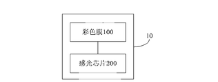
- the image sensor 10 includes a color film 100 and a photosensitive chip 200.
- the color film 100 only allows infrared light of a specific wavelength to pass, and the color film 100 is adjustable for the light intensity ratio of the infrared light of a specific wavelength, and the color film 100 includes a plurality of filters of n colors, Wherein each filter corresponds to one color, and a plurality of filters of n colors are used to distinguish visible light in incident light into light of n colors, where n is a positive integer.
- the color film 100 allows partial transmission of visible light, while for infrared light, the color film 100 allows only infrared light of a specific wavelength to pass, and the ratio of the intensity of the color film 100 to the infrared light of a specific wavelength can be previously Adjusted.
- the color film 100 allows partial visible light transmission, which means that the color film 100 includes filters of a plurality of colors.
- the color film 100 includes red, green, and blue filters, the red filter only allows visible light.
- the green filter only allows the green light in the visible light to pass through
- the blue filter only allows the blue light in the visible light to pass through.
- the photosensitive chip 200 includes a signal processing circuit and a plurality of photosensitive cells corresponding to the plurality of n colors of the filter, and the plurality of photosensitive cells are respectively used for sensing multiple n
- the gain ratio of the signal is A1:A2:...:An, wherein the ratio of the light intensity of the filter of the plurality of n colors of the color film 100 to the infrared light of the specific wavelength is 1: (A1/A2):...:( A1/An).
- the color filter 100 (abbreviated as CF) has light transmission selectivity (that is, only a specific light is allowed to pass) and light attenuation (ie, the intensity of light passing through is lowered).
- the color film 100 includes a plurality of red colors,
- the green and blue filters are used to distinguish visible light in incident light into red, green, and blue primary colors, and for infrared light bands, red, green, and blue filters only allow infrared light of a specific wavelength (for example, a wavelength of 850 nm+ -50 nm infrared light) passed.
- the color film 100 includes red, green, and blue filters for illustrative purposes only.
- the color film 100 may also include filters of other colors.
- the color film 100 may include cyan, magenta (or magenta).
- the yellow filter the color film 100 may include red, green, blue, and white filters.
- the photosensitive chip 200 is located under the color film 100.
- the photosensitive chip 200 includes a signal processing circuit and a plurality of photosensitive cells corresponding to the plurality of n colors of the filter, and the plurality of photosensitive cells are respectively used for sensing and transmitting a plurality of n kinds.
- the intensity of the light of the color filter and the electrical signal corresponding to the light transmitted through the filter of the plurality of n colors, the signal processing circuit is used for processing the electrical signal for imaging, and the gain of the signal processing circuit for the electrical signal
- the ratio is A1:A2:...:An, wherein the ratio of the intensity of the plurality of n colors of the color film to the infrared light of a specific wavelength is 1: (A1/A2):...:(A1/An) .
- the photosensitive unit may be a photodiode.
- Figure 3 shows a schematic of an image sensor. In Fig.
- the three kinds of filters of red, green and blue are arranged in a certain order to form an array, for example, odd-numbered lines (such as the first row, the third row, the fifth row) from left to right.
- the colors are red, green, red, green, red, green..., and even-numbered lines (such as lines 2 and 4) are left to right.
- the color of the filter is green, blue, green, blue, and green. ,blue....
- the photosensitive chip 200 performs imaging based on light of three types of red, green, and blue filters that pass through the color film 100.
- the signal processing circuit processes the corresponding electrical signal according to the order in which the filters are arranged, and restores the real color to form a picture. More specifically, the light passing through the three types of red, green, and blue filters of the color film 100 passes through the photodiode, and the optical signal is converted into an electrical signal, and the electrical signal is processed by the signal processing circuit to generate an image.
- Figure 4 is a schematic illustration of the sensitization of red, green and blue photosensitive cells. Among them, the red, green and blue photosensitive cells are in one-to-one correspondence with the three kinds of red, green and blue filters.
- the gain ratio of the signal processing circuit to the electric signal corresponding to the light passing through the filters of the plurality of n colors is A1:A2:...:An is a plurality of n kinds of color films.
- the color filter is obtained by comparing the intensity of the infrared light of a specific wavelength.
- the ratio of the light intensity of the filter of the plurality of n colors of the color film to the infrared light of the specific wavelength is 1: (A1/A2):...:(A1/An), and then During the test, the light intensity of the infrared light of a specific wavelength according to the filter of the plurality of n colors of the color film passes the electrical signal corresponding to the light of the filter which transmits the filter of the plurality of n colors by the signal processing circuit.
- the gain ratio that is, the gain ratio of the signal processing circuit to the electrical signal is obtained by testing A1:A2:...:An.
- the red, green, and blue filters are still taken as an example.
- the infrared light is filtered out, and only the visible light is left.
- the red, green, and blue photosensitive cells sense the visible light intensity, and are converted into After the electrical signal, it will be input by the signal processing circuit. After the line processing, the image with pure color is output.
- the gain ratio of the signal generated by the signal processing circuit to the three visible lights of red, green and blue is A1:A2:A3.
- the image sensor may be supplemented with a fill light according to a specific application environment of the image sensor, and the fill light emits infrared light of a specific wavelength.
- the particular wavelength matches the wavelength of the infrared light emitted by the optional fill light.
- the color film 100 allows only infrared light of a specific wavelength to pass, and infrared light of other wavelengths cannot pass through the color film 100.
- the infrared light emitted by the fill light has a wavelength of ⁇ (for example using a fill light of 850 nm + -50 nm).
- ⁇ for example using a fill light of 850 nm + -50 nm.
- the optical characteristic of the CF is that the optical characteristics of the visible light band remain unchanged, and in the infrared light band, the infrared light of the ⁇ (850 nm+-50 nm) infrared wavelength used by the nighttime fill lamp is passed.
- Figure 5 (1) shows the optical characteristics of the red filter before adjustment
- Figure 5 (2) shows the optical characteristics of the green filter before adjustment
- Figure 5 (3) shows the blue filter before adjustment
- Figure 6 (1) shows the optical characteristics of the adjusted red filter
- Figure 6 (2) shows the optical characteristics of the adjusted green filter
- Figure 6 (3) shows the adjustment Schematic diagram of the optical properties of the blue filter.
- the photosensitive chip 200 generates a complex spectral signal (visible light + infrared light), and for visible light, a signal processing circuit corresponding to the light transmitted through the three types of red, green and blue filters.
- the gain ratio of the electrical signal is A1:A2:A3, and it is known to those skilled in the art that the three kinds of visible light of red, green and blue can be processed, so that the component ratios of three kinds of visible light of red, green and blue in the obtained image are obtained. It is 1:1:1, so you can restore the true visible color.
- the pass ratio of the plurality of red, green, and blue filters of the color film 100 to the infrared light of a specific wavelength ( ⁇ ) is 1: (A1/A2): (A1/A3), the signal is passed.
- the processing circuit since the gain ratio of the signal generated by the signal processing circuit to the light transmitted through the three filters of red, green and blue is A1:A2:A3, the infrared light passes through the red, green and blue filters.
- the ratio of the color components of the red, green and blue in the infrared of the obtained image is 1:1:1, and the ratio is the gradation of the brightness, so the incidence of the infrared light does not affect the visible light. s color.
- the brightness of the image is brighter and the sharpness is better.
- the photosensitive chip 200 when the photosensitive chip 200 senses a single infrared light (wavelength ⁇ ) emitted by the fill light, since CF is infrared light that allows the wavelength ⁇ , only the fill light is applied at night. When the light is on, the human eye is The method sees the object, but the photosensitive chip 200 can still sense the infrared light of the wavelength ⁇ , and the infrared light passes through the red, green, and blue filters of the light intensity ratio 1: (A1/A2): (A1/A3). The light intensity induced by the photosensitive cells corresponding to the red, green, and blue filters is 1: (A1/A2): (A1/A3).
- the signal processing circuit When processed by the signal processing circuit, the signal processing circuit transmits red, green,
- the gain ratio of the electric signals generated by the light of the three blue filters is A1:A2:A3, so that the ratio of the color components of red, green and blue in the generated image is 1:1:1, and the image at this time is normal. Black and white image.
- the image sensor of the embodiment of the invention has no color cast color in the environment of visible light and infrared light at the same time, and the image brightness and the definition are good, and can be applied in many fields, in particular, it can be applied to security monitoring. .
- the signal processing circuit corresponding to the image sensor of the same model transmits multiple n colors.
- the gain of the electrical signal corresponding to the light of the filter is the same as A1:A2:...:An.
- the gain ratio of the electrical signal can be adjusted by the signal processing circuit according to different scenarios to achieve real color reproduction.
- the image sensor of the embodiment of the present invention when visible light and infrared light are present in the environment (such as in sunlight), by adjusting the optical characteristics of the color film, so that the photosensitive chip receives visible light and infrared light of a specific wavelength, It can be sensitive at the same time, and the intensity ratio of the infrared light of a specific wavelength is adjusted, so that the color of the captured image is consistent with the color observed by the human eye; in an environment where the visible light is weak and the infrared light is strong (such as the night)
- the fill light is used to fill light, the fill light emits infrared light of a specific wavelength)
- the image sensor is better sensitive to infrared light of a specific wavelength, high light perception can still be obtained, and for a specific wavelength
- the infrared light is adjusted by the light intensity ratio, so that a clear black and white image can be taken, and no mechanical device is needed for assistance, and the application range is wide, convenient and reliable.
- the image sensor 10 further includes a microlens 300 located above the color film 100 for receiving and concentrating incident light. Specifically, the light passes through the microlens 300, which converges the light.
- the image sensor 10 may further include a filter 400.
- the filter 400 is located above the microlens 300 for filtering out infrared light other than the specific wavelength of infrared light, so that the filtering effect is better, so that the effect of the captured image is better.
- the filter 400 may also be placed directly on the color film 100.
- the present invention also proposes a monitoring system.
- FIG. 8 is a schematic structural diagram of a monitoring system according to an embodiment of the present invention.
- the monitoring system includes an electronic device 1000 and a fill light 20.
- the electronic device 1000 has an image sensor 10 that emits infrared light of a specific wavelength.
- the color of the captured image is consistent with the color observed by the human eye; the visible light is weak and the infrared light is strong.
- the fill light emits infrared light of a specific wavelength
- still obtain high light perception can take clear black and white images, and the image sensor does not need additional
- the mechanical device is auxiliary, and the application range is wide, and it is convenient and reliable.
- FIG. 9 is a schematic structural view of an image sensor according to another embodiment of the present invention.
- the image sensor 30 includes at least one filter 500, a color film 600, and a photosensitive chip 700.
- the filter 500 is used to filter out infrared light other than infrared light of a specific wavelength.
- the filter 500 allows visible light and infrared light of a specific wavelength to pass therethrough.
- the filter 500 is an IR filter, and the filter 500 is used to filter out infrared light other than infrared light of a specific wavelength. That is, the filter 500 allows visible light and infrared light of a specific wavelength to pass.
- the filter 500 allows visible light and infrared light of a specific wavelength to pass.
- FIG. 10 is a schematic diagram of the optical characteristics of the filter 500.
- the color film 600 is located below the filter 500, wherein the color film 600 includes a plurality of filters of n colors, wherein each filter corresponds to one color, and a plurality of filters of n colors are used for incident
- the visible light in the light is divided into light of n colors, where n is a positive integer.
- the photosensitive chip 700 is disposed under the color film 600.
- the photosensitive chip 700 includes a signal processing circuit and a plurality of photosensitive cells corresponding to the plurality of filters of n colors, and the plurality of photosensitive cells are respectively used for sensing and transmitting a plurality of n kinds of photosensitive cells.
- the intensity of the light of the color filter and the electrical signal corresponding to the light transmitted through the filter of the plurality of n colors, the signal processing circuit is used for processing the electrical signal for imaging, and the gain of the signal processing circuit for the electrical signal
- the ratio is A1:A2:...:An, wherein the ratio of the light intensity of the plurality of n colors of the color film 600 to the infrared light of a specific wavelength is 1: (A1/A2):...: (A1/An ).
- the color filter 600 (abbreviated as CF) has light attenuation (ie, the intensity of light passing through is lowered).
- the color film 600 includes a plurality of red, green, and blue filters for distinguishing visible light in incident light into three primary colors of red, green, and blue.
- the color film 600 includes red, green, and blue filters for illustrative purposes only.
- the color film 600 may also include other color filters.
- the color film 600 may include cyan, magenta (or magenta).
- the yellow filter, as another color film 600 may include red, green, blue, and white filters.
- the photosensitive chip 700 performs imaging based on light of three types of red, green, and blue filters that pass through the color film 600.
- the red, green and blue filters are arranged in a certain order to form an array, and the signal processing circuit blocks are arranged according to the filter.
- the sequence processes the corresponding electrical signals to restore the true color to form a picture. More specifically, after the light passing through the red, green, and blue filters of the color film 600 reaches the underlying photodiode, the optical signal is converted into an electrical signal, and the electrical signal is processed by the signal processing circuit to generate an image.
- the optical characteristics of the color film 600 are adjusted such that the ratio of the light intensity of the plurality of red, green, and blue filters of the color film 600 to the infrared light of a specific wavelength (eg, 850 nm + -50 nm) is 1: (A1/A2) ): (A1/A3). Since the filter 500 can filter infrared light other than the specific wavelength of infrared light, the intensity of the infrared light of other wavelength ranges does not need to be specially adjusted.
- 11(1), 11(2), and 11(3) are schematic views showing the optical characteristics of the red, green, and blue filters, respectively, wherein the broken line in the figure indicates that the value can be an arbitrary value.
- the intensity of all infrared light can be adjusted to 1: (A1/A2): (A1/A3), in fact, other wavelength ranges of infrared light other than the specific wavelength of infrared light
- the light intensity can be adjusted freely.
- the signal processing circuit has a gain ratio A1:A2:...:An for an electrical signal corresponding to light passing through a plurality of filters of n colors, according to a plurality of n colors of the color film. The ratio of the filter to the intensity of the infrared light of a specific wavelength is obtained.
- the ratio of the light intensity of the filter of the plurality of n colors of the color film to the infrared light of the specific wavelength is 1: (A1/A2):...:(A1/An), and then During the test, the light intensity of the infrared light of a specific wavelength according to the filter of the plurality of n colors of the color film passes the electrical signal corresponding to the light of the filter which transmits the filter of the plurality of n colors by the signal processing circuit.
- the gain ratio that is, the gain ratio of the signal processing circuit to the electrical signal, A1:A2:...:An is obtained by testing.
- the red, green, and blue filters are still taken as an example.
- the infrared light is filtered out, and only the visible light is left.
- the red, green, and blue photosensitive cells sense the visible light intensity, and are converted into The electrical signal is processed by the signal processing circuit, and then the image with pure color is output.
- the gain ratio of the signal processing circuit to the electric signals corresponding to the three visible lights of red, green and blue is A1:A2:A3.
- the image sensor may be supplemented with a fill light according to a specific application environment of the image sensor, and the fill light emits infrared light of a specific wavelength.
- the particular wavelength matches the wavelength of the infrared light emitted by the optional fill light. That is, the filter 500 and the selected fill light are used in combination. Specifically, for example, the infrared light emitted by the fill light has a wavelength of ⁇ , and the filter 500 allows the infrared light of the wavelength ⁇ to pass, while the infrared light of the other wavelength is filtered.
- the photosensitive chip 700 senses a complex spectral signal (visible light + infrared light), and for visible light, the signal processing circuit corresponds to the light transmitted through the three types of red, green and blue filters.
- the gain ratio of the signal is A1:A2:A3.
- the three visible lights of red, green and blue can be processed, so that the ratio of the three visible light components of red, green and blue in the obtained image is 1:1:1 so that the real visible The color of the light is restored.
- the ratio of the intensity of the plurality of red, green, and blue filters of the color film 600 to the infrared light of a specific wavelength ( ⁇ ) is 1: (A1/A2): (A1/A3), the signal is passed.
- the processing circuit since the gain ratio of the signal generated by the signal processing circuit to the light transmitted through the three filters of red, green and blue is A1:A2:A3, the infrared light passes through the red, green and blue filters.
- the ratio of the color components of the red, green and blue in the infrared of the obtained image is 1:1:1, and the ratio is the gradation of the brightness, so the incidence of the infrared light does not affect the visible light reduction. s color. Moreover, because of the increased intensity of infrared light, the brightness of the image is brighter and the sharpness is better.
- the photosensitive chip 700 senses a single infrared light (wavelength ⁇ ) emitted by the fill light, because the filter 500 is allowed to transmit infrared light having a wavelength of ⁇ , so only at night When there is a fill light, the human eye cannot see the object.
- the photosensitive chip 700 can still sense infrared light having a wavelength of ⁇ , and the infrared light passes through the red, green, and blue filters of a ratio of 1: (A1/A2): (A1/A3), and is red, green, and The light intensity of the corresponding photosensitive unit of the blue filter is 1: (A1/A2): (A1/A3).
- the signal processing circuit When processed by the signal processing circuit, the signal processing circuit transmits three kinds of filters of red, green and blue.
- the gain ratio of the electric signal corresponding to the light is A1:A2:A3, so that the ratio of the color components of red, green and blue in the generated image is 1:1:1, and the image at this time is a normal black and white image.
- the image sensor of the embodiment of the invention has no color cast color in the environment of visible light and infrared light at the same time, and the image brightness and the definition are good, and can be applied in many fields, in particular, it can be applied to security monitoring. .
- the signal processing circuit corresponding to the image sensor of the same model transmits multiple n colors.
- the light of the filter corresponds to the gain of the electrical signal generated by the ratio A1:A2:...:An.
- the gain ratio of the electrical signal corresponding to the light passing through the filters of the plurality of n colors can be adjusted by the signal processing circuit according to different scenarios to achieve the restoration of the true color.
- the image sensor of the embodiment of the present invention when visible light and infrared light are simultaneously present in the environment (such as in sunlight), the photosensitive chip receives visible light and specific by adjusting the optical characteristics of the color film and using a filter having specific optical characteristics.
- the wavelength of infrared light is used, the two kinds of light can be simultaneously sensitized, and the intensity ratio of the infrared light of a specific wavelength is adjusted, so that the color of the captured image is consistent with the color observed by the human eye;
- the image sensor In environments with strong infrared light (such as when the fill light is used to fill light at night, the fill light emits infrared light of a specific wavelength), since the image sensor has better sensitivity to infrared light of a specific wavelength, it can still be obtained higher.
- the light perception and the adjustment of the intensity ratio of the infrared light of a specific wavelength make it possible to take a clear black and white image without using a mechanical device for a wide range of auxiliary applications, and is convenient and reliable.
- the image sensor 30 further includes: a microlens 800, micro
- the lens 800 is positioned between at least one filter 500 and a color film 600 for receiving and concentrating incident light. Specifically, the light passes through the microlens 800, which converges the light.
- the present invention also proposes a monitoring system.
- FIG. 13 is a block diagram showing the structure of a monitoring system in accordance with one embodiment of the present invention.
- the monitoring system includes an electronic device 2000 and a fill light 40.
- the electronic device 2000 has an image sensor 30 that emits infrared light of a specific wavelength.
- the color of the captured image can be consistent with the color observed by the human eye; the visible light is weak and the infrared light is strong.
- the environment such as when the fill light is used to fill the light at night, the fill light emits infrared light of a specific wavelength
- a clear black and white image can be obtained, and no mechanical device is needed for assistance, and the application range is wide, convenient and reliable.
- first and second are used for descriptive purposes only and are not to be construed as indicating or implying a relative importance or implicitly indicating the number of technical features indicated.
- features defining “first” or “second” may include at least one of the features, either explicitly or implicitly.
- the meaning of "a plurality” is at least two, such as two, three, etc., unless specifically defined otherwise.
- the terms “installation”, “connected”, “connected”, “fixed” and the like shall be understood broadly, and may be either a fixed connection or a detachable connection, unless explicitly stated and defined otherwise. , or integrated; can be mechanical or electrical connection; can be directly connected, or indirectly connected through an intermediate medium, can be the internal communication of two elements or the interaction of two elements, unless otherwise specified Limited.
- the specific meanings of the above terms in the present invention can be understood on a case-by-case basis.
- the first feature "on” or “under” the second feature may be a direct contact of the first and second features, or the first and second features may be indirectly through an intermediate medium, unless otherwise explicitly stated and defined. contact.
- the first feature "above”, “above” and “above” the second feature may be that the first feature is directly above or above the second feature, or merely that the first feature level is higher than the second feature.
- the first feature “below”, “below” and “below” the second feature may be that the first feature is directly below or obliquely below the second feature, or merely that the first feature level is less than the second feature.
Landscapes
- Engineering & Computer Science (AREA)
- Multimedia (AREA)
- Signal Processing (AREA)
- Color Television Image Signal Generators (AREA)
- Solid State Image Pick-Up Elements (AREA)
Abstract
本发明提出一种图像传感器和监控系统,图像传感器包括:彩色膜,对于红外波段的光,彩色膜仅允许特定波长的红外光通过,彩色膜包括多个n种颜色的滤片,其中,每个滤片对应于一种颜色,用于将入射光中的可见光区分为n种颜色的光;感光芯片,包含信号处理电路和多个感光单元,多个感光单元分别感应透过多个n种颜色的滤片的光的光强并生成与透过所述多个n种颜色的滤片的光对应的电信号,信号处理电路对电信号处理以进行成像,信号处理电路对电信号的增益比为A1:A2:…:An,多个n种颜色的滤片对特定波长的红外光的光强通过比为1:(A1/A2):…:(A1/An)。本发明的图像传感器,拍摄的图像色彩与人眼观察到的一致;在可见光较弱而红外光较强时,可拍出清晰的黑白图像,应用范围广且方便、可靠。
Description
本发明涉及图像成像技术领域,特别涉及一种图像传感器和监控系统。
人眼的感光光谱范围为380nm~780nm的可见光谱,而对红外波段光谱则无法觉察。CMOS(Complementary Metal-Oxide-Semiconductor Transistor,互补金属氧化物半导体)图像传感器的感知光谱的范围比人眼要宽,硅基材料对940nm的红外线还可以有较好的感光。在某些应用(如安防监控应用)中,为了使CMOS图像传感器拍摄到较清晰的图像,同时又不想改变人眼观察效果,以免引起警觉,通常会采用红外光灯进行补光。
当环境中同时存在可见光与红外光时(如在阳光下),某些材质的黑色物体对可见光谱完全吸收,但对红外光则会部分反射,对于此类材质的物体,人眼所看到的是黑色,而CMOS图像传感器由于可同时感知可见光和红外光,其成像的颜色并非黑色,而是红紫色。即CMOS图像传感器所拍摄出来的图像颜色与人眼观察所获得的图像颜色会不一致。在某些应用(如安防监控应用)中,一般会要求:当人眼可以清晰观察时(如白天),机器设备所拍摄的图像颜色要忠实于人眼;若人眼无法清晰地观察时(如晚上),机器设备可提供真实的颜色或者是黑白图像。为了解决这一问题,相关技术中的做法是在CMOS图像传感器的感光通路上,CMOS图像传感器感光之前,增加红外线截止滤片(IRfi lter),如图1(a)所示,该滤片仅允许可见光通过而将红外光滤除,红外线截止滤片的光谱特性如图1(b)所示。
其中,该红外截止滤片可以是固定的,也可以是可移动的。但是这将导致以下问题:(1)若该红外截止滤片是固定的,该红外截止滤片使CMOS图像传感器仅能接收到可见光波段的光,从而得到与人眼一致的图像颜色,但是在晚上却不能通过红外灯来进行补光,从而导致CMOS图像传感器拍摄的图像不清晰;(2)若该红外截止滤片是可移动的,在白天光通路上有红外截止滤片,可滤除红外光,从而获得与人眼观察的颜色一致的图片,而在夜晚使用红外补光灯补光时,则移除滤片,允许红外光透过,获得清晰的夜晚图片,那么该红外线截止滤片需要使用机械运动结构,进行滤片的控制、移动,方案成本高、结构复杂,且机械结构可靠性较差,容易损坏,若需要长期在高、低温环境中使用,则无法可靠、稳定地长期正常工作。
发明内容
本发明的目的旨在至少在一定程度上解决上述的技术缺陷之一。
为此,本发明的第一个目的在于提出一种图像传感器。该图像传感器,当环境中同时存在可见光与红外光时(如在阳光下),拍摄的图像的色彩与人眼观察到的色彩一致;在可见光较弱而红外光较强的环境下(如夜晚使用补光灯进行补光时),可拍摄出清晰的黑白图像,应用范围广,且方便、可靠。
本发明的第二个目的在于提出一种监控系统。
本发明的第三个目的在于提出另一种图像传感器。
本发明的第四个目的在于提出另一种监控系统。
为达到上述目的,本发明第一方面实施例的图像传感器,包括:彩色膜,对于红外波段的光,所述彩色膜仅允许特定波长的红外光通过,且所述彩色膜包括多个n种颜色的滤片,其中,每个滤片对应于一种颜色,所述多个n种颜色的滤片用于将入射光中的可见光区分为n种颜色的光,其中n为正整数;以及位于所述彩色膜之下的感光芯片,所述感光芯片包含信号处理电路和与所述多个n种颜色的滤片一一对应的多个感光单元,所述多个感光单元分别用于感应透过所述多个n种颜色的滤片的光的光强并生成与透过所述多个n种颜色的滤片的光对应的电信号,所述信号处理电路用于对所述电信号处理以进行成像,所述信号处理电路对于所述电信号的增益比为A1:A2:…:An,其中,所述彩色膜的所述多个n种颜色的滤片对所述特定波长的红外光的光强通过比为1:(A1/A2):…:(A1/An)。
根据本发明实施例的图像传感器,当环境中同时存在可见光与红外光时(如在阳光下),通过调整彩色膜的光学特性,使感光芯片接收可见光和特定波长的红外光时,对两种光可以同时感光,并且对特定波长的红外光进行光强通过比的调节,使得所拍摄的图像的色彩与人眼观察到的色彩一致;在可见光较弱而红外光较强的环境下(如夜晚使用补光灯进行补光时,补光灯发射特定波长的红外光),由于图像传感器对于特定波长的红外光有较好的感光,仍可获得较高的光线感知度,并且对特定波长的红外光进行光强通过比的调节,使得可以拍摄出清晰的黑白图像,且不需要使用机械装置进行辅助,应用范围广,且方便、可靠。
为达到上述的目的,本发明第二方面实施例的监控系统,包括电子设备,所述电子设备具有本发明第一方面实施例的图像传感器;以及补光灯,所述补光灯发射所述特定波长的红外光。
根据本发明实施例的监控系统,当环境中同时存在可见光和红外光时(如在阳光下),所拍摄的图像的色彩与人眼观察到的色彩一致;在可见光较弱而红外光较强的环境下(如夜晚使用补光灯进行补光时,补光灯发射特定波长的红外光),仍可获得较高
的光线感知度,可以拍摄出清晰的黑白图像,且图像传感器不需要额外的机械装置进行辅助,应用范围广,且方便、可靠。
为达到上述的目的,本发明第三方面实施例的图像传感器,包括:至少一个滤光片,用于滤除除特定波长的红外光之外的红外光,其中,所述滤光片允许可见光和所述特定波长的红外光透过;位于所述滤光片之下的彩色膜,所述彩色膜包括多个n种颜色的滤片,其中,每个滤片对应于一种颜色,所述多个n种颜色的滤片用于将所述入射光中的可见光区分为n种颜色的光,其中n为正整数;以及位于所述彩色膜之下的感光芯片,所述感光芯片包含信号处理电路和与所述多个n种颜色的滤片一一对应的多个感光单元,所述多个感光单元分别用于感应透过所述多个n种颜色的滤片的光的光强并生成与透过所述多个n种颜色的滤片的光对应的电信号,所述信号处理电路用于对所述电信号处理以进行成像,所述信号处理电路对于所述电信号的增益比为A1:A2:…:An,其中,所述彩色膜的所述多个n种颜色的滤片对所述特定波长的红外光的光强通过比为1:(A1/A2):…:(A1/An)。
根据本发明实施例的图像传感器,当环境中同时存在可见光与红外光时(如在阳光下),通过调整彩色膜的光学特性以及使用具有特定光学特性的滤光片,使感光芯片接收可见光和特定波长的红外光时,对两种光可以同时感光,并且对特定波长的红外光进行光强通过比的调节,使得使拍摄的图像的色彩与人眼观察到的色彩一致;在可见光较弱而红外光较强的环境下(如夜晚使用补光灯进行补光时,补光灯发射特定波长的红外光),由于图像传感器对于特定波长的红外光有较好的感光,仍可获得较高的光线感知度,并且对特定波长的红外光进行光强通过比的调节,使得可以拍摄出清晰的黑白图像,且不需要使用机械装置进行辅助应用范围广,且方便、可靠。
为达到上述的目的,本发明第四方面实施例的监控系统,包括电子设备,所述电子设备具有本发明第三方面实施例的图像传感器;以及补光灯,所述补光灯发射所述特定波长的红外光。
根据本发明实施例的监控系统,当环境中同时存在可见光和红外光时(如在阳光下),可以使拍摄的图像的色彩与人眼观察到的色彩一致;在可见光较弱而红外光较强的环境下(如夜晚使用补光灯进行补光时,补光灯发射特定波长的红外光),可以获得清晰的黑白图像,且不需要使用机械装置进行辅助,应用范围广,且方便、可靠。
本发明附加的方面和优点将在下面的描述中部分给出,部分将从下面的描述中变得明显,或通过本发明的实践了解到。
本发明上述的和/或附加的方面和优点从下面结合附图对实施例的描述中将变得明显和容易理解,其中:
图1(a)为相关技术中CMOS图像传感器的感光通路上增加红外线截止滤片的示意图;
图1(b)为相关技术中增加的红外线截止滤片的光谱特性示意图;
图2为根据本发明一个实施例的图像传感器的结构示意图;
图3为根据本发明一个实施例的图像传感器的示意图;
图4为根据本发明一个实施例的红、绿和蓝感光单元进行感光的示意图;
图5(1)为根据本发明一个实施例的调整前红滤片的光学特性示意图;
图5(2)为根据本发明一个实施例的调整前绿滤片的光学特性示意图;
图5(3)为根据本发明一个实施例的调整前蓝滤片的光学特性示意图;
图6(1)为根据本发明一个实施例的调整后红滤片的光学特性示意图;
图6(2)为根据本发明一个实施例的调整后绿滤片的光学特性示意图;
图6(3)为根据本发明一个实施例的调整后蓝滤片的光学特性示意图;
图7(1)为根据本发明另一个实施例的图像传感器的结构示意图;
图7(2)为根据本发明又一个实施例的图像传感器的结构示意图;
图7(3)为根据本发明又一个实施例的图像传感器的结构示意图;
图8为根据本发明一个实施例的监控系统的结构示意图;
图9为根据本发明另一个实施例的图像传感器的结构示意图;
图10为根据本发明一个实施例的滤光片500的光学特性示意图;
图11(1)为根据本发明一个实施例的红滤片的光学特性示意图;
图11(2)为根据本发明一个实施例的绿滤片的光学特性示意图;
图11(3)为根据本发明一个实施例的蓝滤片的光学特性示意图;
图12为根据本发明一个实施例的图像传感器的结构示意图;
图13为根据本发明另一个实施例的监控系统的结构示意图。
下面详细描述本发明的实施例,所述实施例的示例在附图中示出,其中自始至终相同或类似的标号表示相同或类似的元件或具有相同或类似功能的元件。下面通过参考附图描述的实施例是示例性的,仅用于解释本发明,而不能解释为对本发明的限制。
下文的公开提供了许多不同的实施例或例子用来实现本发明的不同结构。为了简化本发明的公开,下文中对特定例子的部件和设置进行描述。当然,它们仅仅为示例,并
且目的不在于限制本发明。此外,本发明可以在不同例子中重复参考数字和/或字母。这种重复是为了简化和清楚的目的,其本身不指示所讨论各种实施例和/或设置之间的关系。此外,本发明提供了的各种特定的工艺和材料的例子,但是本领域普通技术人员可以意识到其他工艺的可应用于性和/或其他材料的使用。另外,以下描述的第一特征在第二特征之“上”的结构可以包括第一和第二特征形成为直接接触的实施例,也可以包括另外的特征形成在第一和第二特征之间的实施例,这样第一和第二特征可能不是直接接触。
在本发明的描述中,需要说明的是,除非另有规定和限定,术语“安装”、“相连”、“连接”应做广义理解,例如,可以是机械连接或电连接,也可以是两个元件内部的连通,可以是直接相连,也可以通过中间媒介间接相连,对于本领域的普通技术人员而言,可以根据具体情况理解上述术语的具体含义。
下面参照附图来描述根据本发明实施例的图像传感器和监控系统。
图2为根据本发明一个实施例的图像传感器的结构示意图。本发明实施例的图像传感器为CMOS图像传感器。如图2所示,图像传感器10包括:彩色膜100、感光芯片200。
其中,对于红外波段,彩色膜100仅允许特定波长的红外光通过,且彩色膜100对于特定波长的红外光的光强通过比可调节,且彩色膜100包括多个n种颜色的滤片,其中,每个滤片对应于一种颜色,多个n种颜色的滤片用于将入射光中的可见光进行区分为n种颜色的光,其中n为正整数。
具体地,对于可见光,彩色膜100允许部分可见光透过,而对于红外光,彩色膜100仅允许特定波长的红外光通过,且彩色膜100对特定波长的红外光的光强通过比是可以事先调节的。其中,对于可见光,彩色膜100允许部分可见光透过,是指彩色膜100包括多个颜色的滤片,如当彩色膜100包括红、绿和蓝滤片时,红滤片只允许可见光中的红光透过,绿滤片只允许可见光中的绿光透过,蓝滤片只允许可见光中的蓝光透过。
位于彩色膜100之下的感光芯片200,感光芯片200包含信号处理电路和与多个n种颜色的滤片一一对应的多个感光单元,多个感光单元分别用于感应透过多个n种颜色的滤片的光的光强并生成与透过所述多个n种颜色的滤片的光对应的电信号,信号处理电路用于对电信号处理以进行成像,信号处理电路对于电信号的增益比为A1:A2:…:An,其中,彩色膜100的多个n种颜色的滤片对特定波长的红外光的光强通过比为1:(A1/A2):…:(A1/An)。
为了方便说明,下面均以n=3,且滤片为红、绿和蓝滤片为例进行描述。
具体地,彩色膜100(Color Filter,可简写为CF)具有透光选择性(即只允许特定的光线通过)及光强衰减性(即通过的光线强度会下降)。彩色膜100包括多个红、
绿和蓝滤片用于将入射光中的可见光进行区分为红、绿、蓝三原色,且对于红外光波段,红、绿和蓝滤片均只允许特定波长的红外光(例如,波长为850nm+-50nm的红外光)通过。
需要说明的是,彩色膜100包括红、绿和蓝滤片只是为了方便说明而做的举例,彩色膜100还可以包括其它颜色的滤片,例如彩色膜100可以包括青、洋红(或品红)和黄滤片,彩色膜100可以包括红、绿、蓝和白滤片。
感光芯片200位于彩色膜100之下,感光芯片200包含信号处理电路和与多个n种颜色的滤片一一对应的多个感光单元,多个感光单元分别用于感应透过多个n种颜色的滤片的光的光强并生成与透过多个n种颜色的滤片的光对应的电信号,信号处理电路用于对电信号处理以进行成像,信号处理电路对于电信号的增益比为A1:A2:…:An,其中,彩色膜的多个n种颜色的滤片对特定波长的红外光的光强通过比为1:(A1/A2):…:(A1/An)。其中,感光单元可以为光敏二极管。图3所示为图像传感器的示意图。图3中,light表示入射光,Micro Lens为微透镜,Color Filter为彩色膜100,Photo Diode为光敏二极管,用于感光,并将光信号转化为电信号。其中,如图3所示,红、绿和蓝三种滤片按照一定次序的排列,构成阵列,例如,奇数行(如第1行、第3行、第5行)从左到右滤片的颜色依此为红、绿、红、绿、红、绿…,偶数行(如第2行、第4行)从左到右滤片的颜色依此为绿、蓝、绿、蓝、绿、蓝…。
具体地,感光芯片200根据透过彩色膜100的红、绿和蓝三种滤片的光进行成像。信号处理电路依滤片排列的次序对对应的电信号进行处理,将真实颜色还原出来,构成图片。更具体地,透过彩色膜100的红、绿和蓝三种滤片的光经过光敏二极管,光信号将转化为电信号,电信号由信号处理电路进行处理后,可生成图像。图4所示为红、绿和蓝感光单元进行感光的示意图。其中,红、绿和蓝感光单元与红、绿和蓝三种滤片一一对应。
此外,在本发明的实施例中,信号处理电路对于与透过多个n种颜色的滤片的光对应的电信号的增益比A1:A2:…:An是根据彩色膜的多个n种颜色的滤片对特定波长的红外光的光强通过比得到的。根据所要形成的图片的要求首先确定彩色膜的多个n种颜色的滤片对特定波长的红外光的光强通过比为1:(A1/A2):…:(A1/An),接着在测试过程中,根据彩色膜的多个n种颜色的滤片对特定波长的红外光的光强通过比确定信号处理电路对于与透过多个n种颜色的滤片的光对应的电信号的增益比,即信号处理电路对于电信号的增益比A1:A2:…:An通过测试得到。
具体地,仍以红、绿和蓝滤片为例,在太阳光下,将红外光滤除,仅剩下可见光,此时红、绿、蓝三种感光单元感应到可见光光强,转变为电信号后会由信号处理电路进
行处理,之后输出颜色纯正的图像,此时信号处理电路对红、绿、蓝三种可见光所对应产生的电信号的增益比为A1:A2:A3。当然,根据需要,本领域技术人员已知可以对红、绿、蓝三种可见光进行处理,使得最后得到的图像中的红、绿、蓝三种可见光的分量比为1:1:1,从而得到与真实物体的颜色一致的图像。
在本发明的一个实施例中,根据图像传感器的具体应用环境可选用补光灯给图像传感器补光,该补光灯发射特定波长的红外光。
在本发明的实施例中,特定波长与选用的补光灯发射的红外光的波长匹配。具体地,在红外波段范围内,彩色膜100只允许特定波长的红外光透过,其它波长的红外光则不能透过彩色膜100。
在本发明的实施例中,在夜晚,补光灯发射的红外光的波长为λ(例如使用850nm+-50nm的补光灯)。通过事先调整CF的光学特性,仅使波长为λ(850nm+-50nm)的红外光可以通过,而其它波段的红外光截止。其中,该CF的光学特性为:可见光波段光学特性保持不变,在红外光波段,使夜晚补光灯采用的λ(850nm+-50nm)红外波长的红外光通过。同时,对于波长为λ(850nm+-50nm)的红外光,彩色膜100的多个红、绿和蓝滤片对于特定波长(λ)的红外光的光强通过比为1:(A1/A2):(A1/A3)。图5(1)所示为调整前红滤片的光学特性示意图,图5(2)所示为调整前绿滤片的光学特性示意图,图5(3)所示为调整前蓝滤片的光学特性示意图,图6(1)所示为调整后红滤片的光学特性示意图,图6(2)所示为调整后绿滤片的光学特性示意图,图6(3)所示为调整后蓝滤片的光学特性示意图。
在本发明的实施例中,感光芯片200在感知复杂的光谱信号时(可见光+红外光),对于可见光,由于信号处理电路对透过红、绿、蓝三种滤片的光所对应产生的电信号的增益比为A1:A2:A3,同时,本领域技术人员已知可以对红、绿、蓝三种可见光进行处理,使得得到的图像中的红、绿、蓝三种可见光的分量比为1:1:1,从而可以将真实的可见光颜色还原出来。而对于红外光,因彩色膜100的多个红、绿和蓝滤片对于特定波长(λ)的红外光的光强通过比为1:(A1/A2):(A1/A3),经过信号处理电路处理时,由于信号处理电路对透过红、绿、蓝三种滤片的光所对应产生的电信号的增益比为A1:A2:A3,因此红外光在经过红、绿、蓝滤片及感光芯片200的处理之后,得到的图像中红外下红、绿、蓝的颜色分量比为1:1:1,此比值为亮度的灰度,因此红外光的入射不会影响可见光还原出来的颜色。而且还因为多了红外光的光强,图像的亮度更亮,清晰度也会更好。
在本发明的实施例中,感光芯片200在感知单一的由补光灯发射的红外光(波长为λ)时,因为CF是允许波长为λ的红外光透射的,因此在晚上仅有补光灯时,人眼无
法看清物体,但是感光芯片200仍然可以感应波长为λ的红外光,红外光经过光强通过比为1:(A1/A2):(A1/A3)的红、绿、蓝滤片后,被红、绿、蓝滤片对应的感光单元感应到的光强为1:(A1/A2):(A1/A3),经过信号处理电路进行处理时,信号处理电路对透过红、绿、蓝三种滤片的光所对应产生的电信号的增益比为A1:A2:A3,从而生成的图像中红、绿、蓝的颜色分量比为1:1:1,此时的图像为正常的黑白图像。
本发明实施例的图像传感器,在同时具有可见光和红外光的环境下,成像颜色不产生偏色,并且图像亮度及清晰度好,可以在较多的领域应用,特别是可以应用在安防监控上。
此外,本发明实施例的图像传感器在加工成产品时,由于参数的不同可以有多种产品型号,一般来说,相同型号的图像传感器对应的所述信号处理电路对于透过多个n种颜色的滤片的光对应的电信号的增益比A1:A2:…:An是相同的。另外,可以根据不同的场景,通过信号处理电路对电信号的增益比进行调节,以实现真实色彩的还原。
本发明实施例的图像传感器,当环境中同时存在可见光与红外光时(如在阳光下),通过调整彩色膜的光学特性,使感光芯片接收可见光和特定波长的红外光时,对两种光可以同时感光,并且对特定波长的红外光进行光强通过比的调节,使得所拍摄的图像的色彩与人眼观察到的色彩一致;在可见光较弱而红外光较强的环境下(如夜晚使用补光灯进行补光时,补光灯发射特定波长的红外光),由于图像传感器对于特定波长的红外光有较好的感光,仍可获得较高的光线感知度,并且对特定波长的红外光进行光强通过比的调节,使得可以拍摄出清晰的黑白图像,且不需要使用机械装置进行辅助,应用范围广,且方便、可靠。
在本发明的另一个实施例中,如图7(1)所示,图像传感器10还包括:微透镜300,微透镜300位于彩色膜100之上,微透镜300用于接收并汇聚入射光。具体地,光线经过微透镜300,微透镜300将光线会聚加强。
在本发明的一个实施例中,如图7(2)所示,图像传感器10还可以包括滤光片400。滤光片400位于微透镜300之上,用于滤除除特定波长的红外光之外的红外光,如此,可使得过滤效果更好,从而使得拍摄出来的图像的效果也更好。
在本发明的另一个实施例中,如图7(3)所示,滤光片400也可以直接放置于彩色膜100之上。
为了实现上述实施例,本发明还提出一种监控系统。
图8为根据本发明一个实施例的监控系统的结构示意图。
如图8所示,监控系统包括电子设备1000和补光灯20。
其中,电子设备1000具有图像传感器10,补光灯20发射特定波长的红外光。
本发明实施例的监控系统,当环境中同时存在可见光和红外光时(如在阳光下),所拍摄的图像的色彩与人眼观察到的色彩一致;在可见光较弱而红外光较强的环境下(如夜晚使用补光灯进行补光时,补光灯发射特定波长的红外光),仍可获得较高的光线感知度,可以拍摄出清晰的黑白图像,且图像传感器不需要额外的机械装置进行辅助,应用范围广,且方便、可靠。
图9为根据本发明另一个实施例的图像传感器的结构示意图。
如图9所示,图像传感器30包括:至少一个滤光片500、彩色膜600和感光芯片700。
其中,滤光片500用于滤除除特定波长的红外光之外的红外光。滤光片500允许可见光和特定波长的红外光透过。
具体地,滤光片500为IR Filter(红外滤光片),滤光片500用于滤除除特定波长的红外光之外的红外光。即,滤光片500允许可见光和特定波长的红外光通过。例如,以特定波长的红外光的波长为(850nm+-50nm)为例,如图10所示为滤光片500的光学特性示意图。
彩色膜600位于滤光片500之下,其中,彩色膜600包括多个n种颜色的滤片,其中,每个滤片对应于一种颜色,多个n种颜色的滤片用于将入射光中的可见光区分为n种颜色的光,其中n为正整数。感光芯片700位于彩色膜600之下,感光芯片700包含信号处理电路和与多个n种颜色的滤片一一对应的多个感光单元,多个感光单元分别用于感应透过多个n种颜色的滤片的光的光强并生成与透过多个n种颜色的滤片的光对应的电信号,信号处理电路用于对电信号处理以进行成像,信号处理电路对于电信号的增益比为A1:A2:…:An,其中,彩色膜600的多个n种颜色的滤片对特定波长的红外光的光强通过比为1:(A1/A2):…:(A1/An)。
为了方便说明,下面均以n=3,且滤片为红、绿和蓝滤片为例进行描述。
具体地,彩色膜600(Color Filter,可简写为CF)具有光强衰减性(即通过的光线强度会下降)。彩色膜600包括多个红、绿和蓝滤片用于将入射光中的可见光区分为红、绿、蓝三原色。
需要说明的是,彩色膜600包括红、绿和蓝滤片只是为了方便说明而做的举例,彩色膜600还可以包括其它颜色的滤片,例如彩色膜600可以包括青、洋红(或品红)和黄滤片,又如彩色膜600可以包括红、绿、蓝和白滤片。
具体地,感光芯片700根据透过彩色膜600的红、绿、蓝三种滤片的光进行成像。红、绿和蓝三种滤片按照一定次序的排列,构成阵列,信号处理电路块依滤片排列的次
序对对应的电信号进行处理,将真实颜色还原出来,构成图片。更具体地,透过彩色膜600的红、绿、蓝三种滤片的光到达底层的光敏二极管后,光信号将转化为电信号,电信号由信号处理电路进行处理后,可生成图像。更具体地,调整彩色膜600的光学特性,使得彩色膜600的多个红、绿和蓝滤片对于特定波长(如850nm+-50nm)的红外光的光强通过比为1:(A1/A2):(A1/A3)。由于滤光片500可以将除特定波长的红外光之外的红外光滤除,所以其它波长范围的红外光的光强通过比不需要做特殊调整。图11(1)、图11(2)和图11(3)所示分别为红、绿、蓝滤片的光学特性的示意图,其中,图中的虚线表示取值可以为任意值。当然,为了方便,可以将所有红外光的光强通过比都调为1:(A1/A2):(A1/A3),实际上除特定波长的红外光之外的其它波长范围的红外光的光强通过比可随意调。
在本发明的实施例中,信号处理电路对于与透过多个n种颜色的滤片的光对应的电信号的增益比A1:A2:…:An是根据彩色膜的多个n种颜色的滤片对特定波长的红外光的光强通过比得到的。根据所要形成的图片的要求首先确定彩色膜的多个n种颜色的滤片对特定波长的红外光的光强通过比为1:(A1/A2):…:(A1/An),接着在测试过程中,根据彩色膜的多个n种颜色的滤片对特定波长的红外光的光强通过比确定信号处理电路对于与透过多个n种颜色的滤片的光对应的电信号的增益比,即信号处理电路对于电信号的增益比A1:A2:…:An是通过测试得到。
具体地,仍以红、绿和蓝滤片为例,在太阳光下,将红外光滤除,仅剩下可见光,此时红、绿、蓝三种感光单元感应到可见光光强,转变为电信号后会由信号处理电路进行处理,之后输出颜色纯正的图像,此时信号处理电路对红、绿、蓝三种可见光所对应的电信号的增益比为A1:A2:A3。当然,根据需要,本领域技术人员已知可以对红、绿、蓝三种可见光进行处理,使得最后得到的图像中的红、绿、蓝三种可见光的分量比为1:1:1,从而得到与真实物体的颜色一致的图像。
在本发明的一个实施例中,根据图像传感器的具体应用环境可选用补光灯给图像传感器补光,该补光灯发射特定波长的红外光。
在本发明的实施例中,特定波长与选用的补光灯发射的红外光的波长匹配。即滤光片500和所选用的补光灯是配合使用的。具体地,例如,补光灯发射的红外光波长为λ,滤光片500则允许波长为λ的红外光通过,而将其它波长的红外光滤除。
在本发明的实施例中,感光芯片700在感知复杂的光谱信号时(可见光+红外光),对于可见光,由于信号处理电路对透过红、绿、蓝三种滤片的光所对应的电信号的增益比为A1:A2:A3,同时,本领域技术人员已知可以对红、绿、蓝三种可见光进行处理,使得得到的图像中的红、绿、蓝三种可见光的分量比为1:1:1,从而可以将真实的可见
光颜色还原出来。而对于红外光,因彩色膜600的多个红、绿和蓝滤片对于特定波长(λ)的红外光的光强通过比为1:(A1/A2):(A1/A3),经过信号处理电路处理时,由于信号处理电路对透过红、绿、蓝三种滤片的光所对应产生的电信号的增益比为A1:A2:A3,因此红外光在经过红、绿、蓝滤片及感光芯片700的处理之后,得到的图像中红外下红、绿、蓝的颜色分量比为1:1:1,此比值为亮度的灰度,因此红外光的入射不会影响可见光还原出来的颜色。而且还因为多了红外光的光强,图像的亮度更亮,清晰度也会更好。
在本发明的实施例中,感光芯片700在感知单一的由补光灯发射的红外光(波长为λ)时,因为滤光片500是允许波长为λ的红外光透射的,因此在晚上仅有补光灯时,人眼无法看清物体。但是感光芯片700仍然可以感应波长为λ的红外光,红外光经过光强通过比为1:(A1/A2):(A1/A3)的红、绿、蓝滤片后,被红、绿、蓝滤片对应的感光单元感应到的光强为1:(A1/A2):(A1/A3),经过信号处理电路进行处理时,信号处理电路对透过红、绿、蓝三种滤片的光所对应产生的电信号的增益比为A1:A2:A3,从而生成的图像中红、绿、蓝的颜色分量比为1:1:1,此时的图像为正常的黑白图像。
本发明实施例的图像传感器,在同时具有可见光和红外光的环境下,成像颜色不产生偏色,并且图像亮度及清晰度好,可以在较多的领域应用,特别是可以应用在安防监控上。
此外,本发明实施例的图像传感器在加工成产品时,由于参数的不同可以有多种产品型号,一般来说,相同型号的图像传感器对应的所述信号处理电路对于透过多个n种颜色的滤片的光对应产生的电信号的增益比A1:A2:…:An是相同的。另外,可以根据不同的场景,通过信号处理电路对与透过多个n种颜色的滤片的光对应的电信号的增益比进行调节,以实现真实色彩的还原。
本发明实施例的图像传感器,当环境中同时存在可见光与红外光时(如在阳光下),通过调整彩色膜的光学特性以及使用具有特定光学特性的滤光片,使感光芯片接收可见光和特定波长的红外光时,对两种光可以同时感光,并且对特定波长的红外光进行光强通过比的调节,使得使拍摄的图像的色彩与人眼观察到的色彩一致;在可见光较弱而红外光较强的环境下(如夜晚使用补光灯进行补光时,补光灯发射特定波长的红外光),由于图像传感器对于特定波长的红外光有较好的感光,仍可获得较高的光线感知度,并且对特定波长的红外光进行光强通过比的调节,使得可以拍摄出清晰的黑白图像,且不需要使用机械装置进行辅助应用范围广,且方便、可靠。
在本发明的一个实施例中,如图12所示,图像传感器30还包括:微透镜800,微
透镜800位于至少一个滤光片500和彩色膜600之间,微透镜800用于接收并汇聚入射光。具体地,光线经过微透镜800,微透镜800将光线会聚加强。
为了实现上述实施例,本发明还提出一种监控系统。
图13为根据本发明一个实施例的监控系统的结构示意图。
如图13所示,监控系统包括电子设备2000和补光灯40。
其中,电子设备2000具有图像传感器30,补光灯40发射特定波长的红外光。
本发明实施例的监控系统,当环境中同时存在可见光和红外光时(如在阳光下),可以使拍摄的图像的色彩与人眼观察到的色彩一致;在可见光较弱而红外光较强的环境下(如夜晚使用补光灯进行补光时,补光灯发射特定波长的红外光),可以获得清晰的黑白图像,且不需要使用机械装置进行辅助,应用范围广,且方便、可靠。
在本发明的描述中,需要理解的是,术语“中心”、“纵向”、“横向”、“长度”、“宽度”、“厚度”、“上”、“下”、“前”、“后”、“左”、“右”、“竖直”、“水平”、“顶”、“底”“内”、“外”、“顺时针”、“逆时针”、“轴向”、“径向”、“周向”等指示的方位或位置关系为基于附图所示的方位或位置关系,仅是为了便于描述本发明和简化描述,而不是指示或暗示所指的装置或元件必须具有特定的方位、以特定的方位构造和操作,因此不能理解为对本发明的限制。
此外,术语“第一”、“第二”仅用于描述目的,而不能理解为指示或暗示相对重要性或者隐含指明所指示的技术特征的数量。由此,限定有“第一”、“第二”的特征可以明示或者隐含地包括至少一个该特征。在本发明的描述中,“多个”的含义是至少两个,例如两个,三个等,除非另有明确具体的限定。
在本发明中,除非另有明确的规定和限定,术语“安装”、“相连”、“连接”、“固定”等术语应做广义理解,例如,可以是固定连接,也可以是可拆卸连接,或成一体;可以是机械连接,也可以是电连接;可以是直接相连,也可以通过中间媒介间接相连,可以是两个元件内部的连通或两个元件的相互作用关系,除非另有明确的限定。对于本领域的普通技术人员而言,可以根据具体情况理解上述术语在本发明中的具体含义。
在本发明中,除非另有明确的规定和限定,第一特征在第二特征“上”或“下”可以是第一和第二特征直接接触,或第一和第二特征通过中间媒介间接接触。而且,第一特征在第二特征“之上”、“上方”和“上面”可是第一特征在第二特征正上方或斜上方,或仅仅表示第一特征水平高度高于第二特征。第一特征在第二特征“之下”、“下方”和“下面”可以是第一特征在第二特征正下方或斜下方,或仅仅表示第一特征水平高度小于第二特征。
在本说明书的描述中,参考术语“一个实施例”、“一些实施例”、“示例”、“具体示例”、或“一些示例”等的描述意指结合该实施例或示例描述的具体特征、结构、材料或者特点包含于本发明的至少一个实施例或示例中。在本说明书中,对上述术语的示意性表述不必须针对的是相同的实施例或示例。而且,描述的具体特征、结构、材料或者特点可以在任一个或多个实施例或示例中以合适的方式结合。此外,在不相互矛盾的情况下,本领域的技术人员可以将本说明书中描述的不同实施例或示例以及不同实施例或示例的特征进行结合和组合。
尽管上面已经示出和描述了本发明的实施例,可以理解的是,上述实施例是示例性的,不能理解为对本发明的限制,本领域的普通技术人员在本发明的范围内可以对上述实施例进行变化、修改、替换和变型。
Claims (10)
- 一种图像传感器,其特征在于,包括:彩色膜,对于红外波段的光,所述彩色膜仅允许特定波长的红外光通过,且所述彩色膜包括多个n种颜色的滤片,其中,每个滤片对应于一种颜色,所述多个n种颜色的滤片用于将入射光中的可见光区分为n种颜色的光,其中n为正整数;以及位于所述彩色膜之下的感光芯片,所述感光芯片包含信号处理电路和与所述多个n种颜色的滤片一一对应的多个感光单元,所述多个感光单元分别用于感应透过所述多个n种颜色的滤片的光的光强并生成与透过所述多个n种颜色的滤片的光对应的电信号,所述信号处理电路用于对所述电信号处理以进行成像,所述信号处理电路对于所述电信号的增益比为A1:A2:…:An,其中,所述彩色膜的所述多个n种颜色的滤片对所述特定波长的红外光的光强通过比为1:(A1/A2):…:(A1/An)。
- 如权利要求1所述的图像传感器,其特征在于,还包括:位于所述彩色膜之上的微透镜,所述微透镜用于接收并汇聚所述入射光。
- 如权利要求1或2所述的图像传感器,其特征在于,所述信号处理电路对于所述电信号的增益比A1:A2:…:An是根据所述彩色膜的所述多个n种颜色的滤片对所述特定波长的红外光的光强通过比得到的。
- 如权利要求2所述的图像传感器,其特征在于,还包括:位于所述微透镜之上的滤光片,用于滤除除所述特定波长的红外光之外的红外光。
- 如权利要求1-3任一项所述的图像传感器,其特征在于,还包括:位于所述彩色膜之上的滤光片,用于滤除除所述特定波长的红外光之外的红外光。
- 一种监控系统,其特征在于,包括:电子设备,所述电子设备具有如权利要求1-5任一项所述图像传感器;以及补光灯,所述补光灯发射所述特定波长的红外光。
- 一种图像传感器,其特征在于,包括:至少一个滤光片,用于滤除除特定波长的红外光之外的红外光,其中,所述滤光片允许可见光和所述特定波长的红外光透过;位于所述滤光片之下的彩色膜,所述彩色膜包括多个n种颜色的滤片,其中,每个滤片对应于一种颜色,所述多个n种颜色的滤片用于将入射光中的可见光区分为n种颜色的光,其中n为正整数;以及位于所述彩色膜之下的感光芯片,所述感光芯片包含信号处理电路和与所述多个n 种颜色的滤片一一对应的多个感光单元,所述多个感光单元分别用于感应透过所述多个n种颜色的滤片的光的光强并生成与透过所述多个n种颜色的滤片的光对应的电信号,所述信号处理电路用于对所述电信号处理以进行成像,所述信号处理电路对于所述电信号的增益比为A1:A2:…:An,其中,所述彩色膜的所述多个n种颜色的滤片对所述特定波长的红外光的光强通过比为1:(A1/A2):…:(A1/An)。
- 如权利要求7所述的图像传感器,其特征在于,还包括:位于所述至少一个滤光片和所述彩色膜之间的微透镜,用于接收并汇聚所述入射光。
- 如权利要求7或8所述的图像传感器,其特征在于,所述信号处理电路对于所述电信号的增益比A1:A2:…:An是根据所述彩色膜的所述多个n种颜色的滤片对所述特定波长的红外光的光强通过比得到的。
- 一种监控系统,其特征在于,包括:电子设备,所述电子设备具有如权利要求7-9任一项所述图像传感器;以及补光灯,所述补光灯发射所述特定波长的红外光。
Priority Applications (2)
| Application Number | Priority Date | Filing Date | Title |
|---|---|---|---|
| EP15780600.1A EP3133805A4 (en) | 2014-04-13 | 2015-04-03 | Image sensor and monitoring system |
| US15/300,204 US20170134669A1 (en) | 2014-04-13 | 2015-04-03 | Image sensor and monitoring system |
Applications Claiming Priority (2)
| Application Number | Priority Date | Filing Date | Title |
|---|---|---|---|
| CN201410149394.7A CN104980628B (zh) | 2014-04-13 | 2014-04-13 | 图像传感器和监控系统 |
| CN201410149394.7 | 2014-04-13 |
Publications (1)
| Publication Number | Publication Date |
|---|---|
| WO2015158210A1 true WO2015158210A1 (zh) | 2015-10-22 |
Family
ID=54276692
Family Applications (1)
| Application Number | Title | Priority Date | Filing Date |
|---|---|---|---|
| PCT/CN2015/075873 Ceased WO2015158210A1 (zh) | 2014-04-13 | 2015-04-03 | 图像传感器和监控系统 |
Country Status (5)
| Country | Link |
|---|---|
| US (1) | US20170134669A1 (zh) |
| EP (1) | EP3133805A4 (zh) |
| CN (1) | CN104980628B (zh) |
| TW (1) | TWI558203B (zh) |
| WO (1) | WO2015158210A1 (zh) |
Families Citing this family (6)
| Publication number | Priority date | Publication date | Assignee | Title |
|---|---|---|---|---|
| CN108111769A (zh) * | 2018-03-07 | 2018-06-01 | 深圳新亮智能技术有限公司 | 利用红外激光和白光混合照明拍摄彩色图片的系统及方法 |
| CN109068111A (zh) * | 2018-10-12 | 2018-12-21 | 北京地平线机器人技术研发有限公司 | 一种监控装置、监控方法和电子设备 |
| CN110418038A (zh) * | 2019-07-10 | 2019-11-05 | 中山联合光电科技股份有限公司 | 一种双光拍摄系统 |
| CN115176454A (zh) * | 2019-12-27 | 2022-10-11 | 日本株式会社皆爱公司 | 拍摄装置 |
| CN113163124B (zh) * | 2020-01-22 | 2022-06-03 | 杭州海康威视数字技术股份有限公司 | 一种成像系统及图像处理方法 |
| CN113824905B (zh) * | 2020-06-18 | 2025-07-01 | 思特威(上海)电子科技股份有限公司 | 暗景全彩功能图像传感器及其制备方法 |
Citations (3)
| Publication number | Priority date | Publication date | Assignee | Title |
|---|---|---|---|---|
| CN101075626A (zh) * | 2006-05-19 | 2007-11-21 | 夏普株式会社 | 彩色传感器、彩色传感器的制造方法、传感器以及电子仪器 |
| CN101309429A (zh) * | 2007-05-15 | 2008-11-19 | 索尼株式会社 | 处理视频信号的设备和方法、成像设备和计算机程序 |
| JP2012054809A (ja) * | 2010-09-02 | 2012-03-15 | Ricoh Co Ltd | 画像センサ及びこの画像センサを用いた撮像装置及びこの撮像装置を用いた車載用監視装置 |
Family Cites Families (15)
| Publication number | Priority date | Publication date | Assignee | Title |
|---|---|---|---|---|
| JP3922238B2 (ja) * | 2003-10-22 | 2007-05-30 | ソニー株式会社 | 光量制御装置およびカメラ装置 |
| JP2006109120A (ja) * | 2004-10-06 | 2006-04-20 | Funai Electric Co Ltd | 赤外線撮像装置 |
| CN1971927B (zh) * | 2005-07-21 | 2012-07-18 | 索尼株式会社 | 物理信息获取方法、物理信息获取装置和半导体器件 |
| JP4971816B2 (ja) * | 2007-02-05 | 2012-07-11 | 三洋電機株式会社 | 撮像装置 |
| WO2008131313A2 (en) * | 2007-04-18 | 2008-10-30 | Invisage Technologies, Inc. | Materials systems and methods for optoelectronic devices |
| JP2009253579A (ja) * | 2008-04-04 | 2009-10-29 | Panasonic Corp | 撮像装置、画像処理装置及び画像処理方法並びに画像処理プログラム |
| JP5178458B2 (ja) * | 2008-10-31 | 2013-04-10 | キヤノン株式会社 | 固体撮像装置、撮像システム、および、固体撮像装置の駆動方法 |
| US9183425B2 (en) * | 2009-04-09 | 2015-11-10 | Hand Held Products, Inc. | Image sensor pixel array having output response curve including logarithmic pattern for image sensor based terminal |
| JP5834386B2 (ja) * | 2010-08-20 | 2015-12-24 | ソニー株式会社 | 光学センサ、レンズモジュール、およびカメラモジュール |
| TWI434404B (zh) * | 2010-12-07 | 2014-04-11 | Ind Tech Res Inst | 彩色濾光片與影像感測器 |
| JP2013041878A (ja) * | 2011-08-11 | 2013-02-28 | Sony Corp | 撮像装置およびカメラモジュール |
| US9143704B2 (en) * | 2012-01-20 | 2015-09-22 | Htc Corporation | Image capturing device and method thereof |
| US9177983B2 (en) * | 2012-01-23 | 2015-11-03 | Omnivision Technologies, Inc. | Image sensor with optical filters having alternating polarization for 3D imaging |
| US10014335B2 (en) * | 2012-09-14 | 2018-07-03 | Panasonic Intellectual Property Management Co., Ltd. | Solid-state imaging device and camera module |
| CN102891968A (zh) * | 2012-10-25 | 2013-01-23 | 中国兵器工业集团第二一四研究所苏州研发中心 | 基于crt驱动电路实现emccd高压驱动信号的系统 |
-
2014
- 2014-04-13 CN CN201410149394.7A patent/CN104980628B/zh active Active
- 2014-11-04 TW TW103138174A patent/TWI558203B/zh active
-
2015
- 2015-04-03 US US15/300,204 patent/US20170134669A1/en not_active Abandoned
- 2015-04-03 WO PCT/CN2015/075873 patent/WO2015158210A1/zh not_active Ceased
- 2015-04-03 EP EP15780600.1A patent/EP3133805A4/en not_active Withdrawn
Patent Citations (3)
| Publication number | Priority date | Publication date | Assignee | Title |
|---|---|---|---|---|
| CN101075626A (zh) * | 2006-05-19 | 2007-11-21 | 夏普株式会社 | 彩色传感器、彩色传感器的制造方法、传感器以及电子仪器 |
| CN101309429A (zh) * | 2007-05-15 | 2008-11-19 | 索尼株式会社 | 处理视频信号的设备和方法、成像设备和计算机程序 |
| JP2012054809A (ja) * | 2010-09-02 | 2012-03-15 | Ricoh Co Ltd | 画像センサ及びこの画像センサを用いた撮像装置及びこの撮像装置を用いた車載用監視装置 |
Non-Patent Citations (1)
| Title |
|---|
| See also references of EP3133805A4 * |
Also Published As
| Publication number | Publication date |
|---|---|
| CN104980628B (zh) | 2018-09-11 |
| US20170134669A1 (en) | 2017-05-11 |
| EP3133805A1 (en) | 2017-02-22 |
| TW201540067A (zh) | 2015-10-16 |
| CN104980628A (zh) | 2015-10-14 |
| TWI558203B (zh) | 2016-11-11 |
| EP3133805A4 (en) | 2017-12-13 |
Similar Documents
| Publication | Publication Date | Title |
|---|---|---|
| TWI558203B (zh) | 圖像感測器和監控系統 | |
| JP7314976B2 (ja) | 撮像装置及び撮像方法 | |
| TWI249950B (en) | Color imaging element and color signal processing circuit | |
| US8035710B2 (en) | Solid-state imaging device and signal processing method | |
| WO2017193738A1 (zh) | 图像传感器、成像方法和成像装置 | |
| CA2812860C (en) | Digital multi-spectral camera system having at least two independent digital cameras | |
| TWI554109B (zh) | 圖像傳感器、監控系統和圖像傳感器的設計方法 | |
| KR20100103504A (ko) | 칼라-모자이크 이미저로부터 전정색 응답을 성취하는 방법 및 장치 | |
| US9188841B2 (en) | Imaging device | |
| US9232151B1 (en) | Single sensor two-sided camera | |
| KR20140000130A (ko) | 촬상 장치 | |
| CN104994361A (zh) | 一种采集物体标准颜色信息的彩色成像系统及其使用方法 | |
| WO2010005595A1 (en) | Spectral improvement of digital camera color images | |
| US9432642B2 (en) | Imaging system and method having extended depth of field | |
| US9113096B1 (en) | Single sensor two-sided camera | |
| CN204859430U (zh) | 一种采集物体标准颜色信息的彩色成像系统 | |
| JP4874752B2 (ja) | デジタルカメラ | |
| EP2907300A1 (en) | System for capturing scene and nir relighting effects in movie postproduction transmission | |
| Skorka et al. | Color correction for RGB sensors with dual-band filters for in-cabin imaging applications | |
| CN206790586U (zh) | 一种可分双光的拍摄装置 | |
| CN105323567A (zh) | 色彩处理系统及装置 | |
| WO2015008383A1 (ja) | 撮像装置 | |
| CN206640680U (zh) | 一种双光可调的拍摄装置 | |
| CN109314746A (zh) | 图像传感器及其获取图像的方法、智能设备 | |
| JP4342149B2 (ja) | 固体撮像素子と撮像装置 |
Legal Events
| Date | Code | Title | Description |
|---|---|---|---|
| 121 | Ep: the epo has been informed by wipo that ep was designated in this application |
Ref document number: 15780600 Country of ref document: EP Kind code of ref document: A1 |
|
| WWE | Wipo information: entry into national phase |
Ref document number: 15300204 Country of ref document: US |
|
| REEP | Request for entry into the european phase |
Ref document number: 2015780600 Country of ref document: EP |
|
| WWE | Wipo information: entry into national phase |
Ref document number: 2015780600 Country of ref document: EP |
|
| NENP | Non-entry into the national phase |
Ref country code: DE |