WO2015159421A1 - エネルギー管理コントローラ、エネルギー管理システム、充放電制御方法及びプログラム - Google Patents
エネルギー管理コントローラ、エネルギー管理システム、充放電制御方法及びプログラム Download PDFInfo
- Publication number
- WO2015159421A1 WO2015159421A1 PCT/JP2014/061018 JP2014061018W WO2015159421A1 WO 2015159421 A1 WO2015159421 A1 WO 2015159421A1 JP 2014061018 W JP2014061018 W JP 2014061018W WO 2015159421 A1 WO2015159421 A1 WO 2015159421A1
- Authority
- WO
- WIPO (PCT)
- Prior art keywords
- charge
- storage battery
- operation mode
- energy management
- discharge control
- Prior art date
- Legal status (The legal status is an assumption and is not a legal conclusion. Google has not performed a legal analysis and makes no representation as to the accuracy of the status listed.)
- Ceased
Links
Images


Classifications
-
- B—PERFORMING OPERATIONS; TRANSPORTING
- B60—VEHICLES IN GENERAL
- B60L—PROPULSION OF ELECTRICALLY-PROPELLED VEHICLES; SUPPLYING ELECTRIC POWER FOR AUXILIARY EQUIPMENT OF ELECTRICALLY-PROPELLED VEHICLES; ELECTRODYNAMIC BRAKE SYSTEMS FOR VEHICLES IN GENERAL; MAGNETIC SUSPENSION OR LEVITATION FOR VEHICLES; MONITORING OPERATING VARIABLES OF ELECTRICALLY-PROPELLED VEHICLES; ELECTRIC SAFETY DEVICES FOR ELECTRICALLY-PROPELLED VEHICLES
- B60L55/00—Arrangements for supplying energy stored within a vehicle to a power network, i.e. vehicle-to-grid [V2G] arrangements
-
- B—PERFORMING OPERATIONS; TRANSPORTING
- B60—VEHICLES IN GENERAL
- B60L—PROPULSION OF ELECTRICALLY-PROPELLED VEHICLES; SUPPLYING ELECTRIC POWER FOR AUXILIARY EQUIPMENT OF ELECTRICALLY-PROPELLED VEHICLES; ELECTRODYNAMIC BRAKE SYSTEMS FOR VEHICLES IN GENERAL; MAGNETIC SUSPENSION OR LEVITATION FOR VEHICLES; MONITORING OPERATING VARIABLES OF ELECTRICALLY-PROPELLED VEHICLES; ELECTRIC SAFETY DEVICES FOR ELECTRICALLY-PROPELLED VEHICLES
- B60L53/00—Methods of charging batteries, specially adapted for electric vehicles; Charging stations or on-board charging equipment therefor; Exchange of energy storage elements in electric vehicles
- B60L53/30—Constructional details of charging stations
- B60L53/305—Communication interfaces
-
- B—PERFORMING OPERATIONS; TRANSPORTING
- B60—VEHICLES IN GENERAL
- B60L—PROPULSION OF ELECTRICALLY-PROPELLED VEHICLES; SUPPLYING ELECTRIC POWER FOR AUXILIARY EQUIPMENT OF ELECTRICALLY-PROPELLED VEHICLES; ELECTRODYNAMIC BRAKE SYSTEMS FOR VEHICLES IN GENERAL; MAGNETIC SUSPENSION OR LEVITATION FOR VEHICLES; MONITORING OPERATING VARIABLES OF ELECTRICALLY-PROPELLED VEHICLES; ELECTRIC SAFETY DEVICES FOR ELECTRICALLY-PROPELLED VEHICLES
- B60L53/00—Methods of charging batteries, specially adapted for electric vehicles; Charging stations or on-board charging equipment therefor; Exchange of energy storage elements in electric vehicles
- B60L53/30—Constructional details of charging stations
- B60L53/31—Charging columns specially adapted for electric vehicles
-
- B—PERFORMING OPERATIONS; TRANSPORTING
- B60—VEHICLES IN GENERAL
- B60L—PROPULSION OF ELECTRICALLY-PROPELLED VEHICLES; SUPPLYING ELECTRIC POWER FOR AUXILIARY EQUIPMENT OF ELECTRICALLY-PROPELLED VEHICLES; ELECTRODYNAMIC BRAKE SYSTEMS FOR VEHICLES IN GENERAL; MAGNETIC SUSPENSION OR LEVITATION FOR VEHICLES; MONITORING OPERATING VARIABLES OF ELECTRICALLY-PROPELLED VEHICLES; ELECTRIC SAFETY DEVICES FOR ELECTRICALLY-PROPELLED VEHICLES
- B60L53/00—Methods of charging batteries, specially adapted for electric vehicles; Charging stations or on-board charging equipment therefor; Exchange of energy storage elements in electric vehicles
- B60L53/50—Charging stations characterised by energy-storage or power-generation means
- B60L53/51—Photovoltaic means
-
- B—PERFORMING OPERATIONS; TRANSPORTING
- B60—VEHICLES IN GENERAL
- B60L—PROPULSION OF ELECTRICALLY-PROPELLED VEHICLES; SUPPLYING ELECTRIC POWER FOR AUXILIARY EQUIPMENT OF ELECTRICALLY-PROPELLED VEHICLES; ELECTRODYNAMIC BRAKE SYSTEMS FOR VEHICLES IN GENERAL; MAGNETIC SUSPENSION OR LEVITATION FOR VEHICLES; MONITORING OPERATING VARIABLES OF ELECTRICALLY-PROPELLED VEHICLES; ELECTRIC SAFETY DEVICES FOR ELECTRICALLY-PROPELLED VEHICLES
- B60L53/00—Methods of charging batteries, specially adapted for electric vehicles; Charging stations or on-board charging equipment therefor; Exchange of energy storage elements in electric vehicles
- B60L53/60—Monitoring or controlling charging stations
- B60L53/63—Monitoring or controlling charging stations in response to network capacity
-
- B—PERFORMING OPERATIONS; TRANSPORTING
- B60—VEHICLES IN GENERAL
- B60L—PROPULSION OF ELECTRICALLY-PROPELLED VEHICLES; SUPPLYING ELECTRIC POWER FOR AUXILIARY EQUIPMENT OF ELECTRICALLY-PROPELLED VEHICLES; ELECTRODYNAMIC BRAKE SYSTEMS FOR VEHICLES IN GENERAL; MAGNETIC SUSPENSION OR LEVITATION FOR VEHICLES; MONITORING OPERATING VARIABLES OF ELECTRICALLY-PROPELLED VEHICLES; ELECTRIC SAFETY DEVICES FOR ELECTRICALLY-PROPELLED VEHICLES
- B60L53/00—Methods of charging batteries, specially adapted for electric vehicles; Charging stations or on-board charging equipment therefor; Exchange of energy storage elements in electric vehicles
- B60L53/60—Monitoring or controlling charging stations
- B60L53/64—Optimising energy costs, e.g. responding to electricity rates
-
- B—PERFORMING OPERATIONS; TRANSPORTING
- B60—VEHICLES IN GENERAL
- B60L—PROPULSION OF ELECTRICALLY-PROPELLED VEHICLES; SUPPLYING ELECTRIC POWER FOR AUXILIARY EQUIPMENT OF ELECTRICALLY-PROPELLED VEHICLES; ELECTRODYNAMIC BRAKE SYSTEMS FOR VEHICLES IN GENERAL; MAGNETIC SUSPENSION OR LEVITATION FOR VEHICLES; MONITORING OPERATING VARIABLES OF ELECTRICALLY-PROPELLED VEHICLES; ELECTRIC SAFETY DEVICES FOR ELECTRICALLY-PROPELLED VEHICLES
- B60L58/00—Methods or circuit arrangements for monitoring or controlling batteries or fuel cells, specially adapted for electric vehicles
- B60L58/10—Methods or circuit arrangements for monitoring or controlling batteries or fuel cells, specially adapted for electric vehicles for monitoring or controlling batteries
- B60L58/12—Methods or circuit arrangements for monitoring or controlling batteries or fuel cells, specially adapted for electric vehicles for monitoring or controlling batteries responding to state of charge [SoC]
-
- H—ELECTRICITY
- H02—GENERATION; CONVERSION OR DISTRIBUTION OF ELECTRIC POWER
- H02J—ELECTRIC POWER NETWORKS; CIRCUIT ARRANGEMENTS OR SYSTEMS FOR SUPPLYING OR DISTRIBUTING ELECTRIC POWER; SYSTEMS FOR STORING ELECTRIC ENERGY
- H02J3/00—Circuit arrangements for AC mains or AC distribution networks
- H02J3/12—Arrangements for adjusting voltage in AC networks by changing a characteristic of the network load
- H02J3/14—Arrangements for adjusting voltage in AC networks by changing a characteristic of the network load by switching loads on to, or off from, the networks, e.g. progressively balanced loading
-
- H—ELECTRICITY
- H02—GENERATION; CONVERSION OR DISTRIBUTION OF ELECTRIC POWER
- H02J—ELECTRIC POWER NETWORKS; CIRCUIT ARRANGEMENTS OR SYSTEMS FOR SUPPLYING OR DISTRIBUTING ELECTRIC POWER; SYSTEMS FOR STORING ELECTRIC ENERGY
- H02J3/00—Circuit arrangements for AC mains or AC distribution networks
- H02J3/28—Arrangements for balancing of the load in networks by storage of energy
- H02J3/32—Arrangements for balancing of the load in networks by storage of energy using batteries or super capacitors with converting means
- H02J3/322—Arrangements for balancing of the load in networks by storage of energy using batteries or super capacitors with converting means the battery being on-board an electric or hybrid vehicle, e.g. vehicle to grid arrangements [V2G], power aggregation, use of the battery for network load balancing, coordinated or cooperative battery charging
-
- H—ELECTRICITY
- H02—GENERATION; CONVERSION OR DISTRIBUTION OF ELECTRIC POWER
- H02J—ELECTRIC POWER NETWORKS; CIRCUIT ARRANGEMENTS OR SYSTEMS FOR SUPPLYING OR DISTRIBUTING ELECTRIC POWER; SYSTEMS FOR STORING ELECTRIC ENERGY
- H02J3/00—Circuit arrangements for AC mains or AC distribution networks
- H02J3/38—Arrangements for feeding a single network from two or more generators or sources in parallel; Arrangements for feeding already energised networks from additional generators or sources in parallel
- H02J3/381—Dispersed generators
-
- H—ELECTRICITY
- H02—GENERATION; CONVERSION OR DISTRIBUTION OF ELECTRIC POWER
- H02J—ELECTRIC POWER NETWORKS; CIRCUIT ARRANGEMENTS OR SYSTEMS FOR SUPPLYING OR DISTRIBUTING ELECTRIC POWER; SYSTEMS FOR STORING ELECTRIC ENERGY
- H02J3/00—Circuit arrangements for AC mains or AC distribution networks
- H02J3/38—Arrangements for feeding a single network from two or more generators or sources in parallel; Arrangements for feeding already energised networks from additional generators or sources in parallel
- H02J3/46—Controlling the sharing of generated power between the generators, sources or networks
- H02J3/466—Scheduling or selectively controlling the operation of the generators or sources, e.g. connecting or disconnecting generators to meet a demand
-
- H—ELECTRICITY
- H02—GENERATION; CONVERSION OR DISTRIBUTION OF ELECTRIC POWER
- H02J—ELECTRIC POWER NETWORKS; CIRCUIT ARRANGEMENTS OR SYSTEMS FOR SUPPLYING OR DISTRIBUTING ELECTRIC POWER; SYSTEMS FOR STORING ELECTRIC ENERGY
- H02J7/00—Circuit arrangements for charging or discharging batteries or for supplying loads from batteries
- H02J7/90—Regulation of charging or discharging current or voltage
-
- H—ELECTRICITY
- H02—GENERATION; CONVERSION OR DISTRIBUTION OF ELECTRIC POWER
- H02J—ELECTRIC POWER NETWORKS; CIRCUIT ARRANGEMENTS OR SYSTEMS FOR SUPPLYING OR DISTRIBUTING ELECTRIC POWER; SYSTEMS FOR STORING ELECTRIC ENERGY
- H02J2101/00—Supply or distribution of decentralised, dispersed or local electric power generation
- H02J2101/20—Dispersed power generation using renewable energy sources
- H02J2101/22—Solar energy
- H02J2101/24—Photovoltaics
-
- H—ELECTRICITY
- H02—GENERATION; CONVERSION OR DISTRIBUTION OF ELECTRIC POWER
- H02J—ELECTRIC POWER NETWORKS; CIRCUIT ARRANGEMENTS OR SYSTEMS FOR SUPPLYING OR DISTRIBUTING ELECTRIC POWER; SYSTEMS FOR STORING ELECTRIC ENERGY
- H02J2105/00—Networks for supplying or distributing electric power characterised by their spatial reach or by the load
- H02J2105/50—Networks for supplying or distributing electric power characterised by their spatial reach or by the load for selectively controlling the operation of the loads
- H02J2105/54—Networks for supplying or distributing electric power characterised by their spatial reach or by the load for selectively controlling the operation of the loads according to a non-electrical condition, e.g. temperature
- H02J2105/55—Networks for supplying or distributing electric power characterised by their spatial reach or by the load for selectively controlling the operation of the loads according to a non-electrical condition, e.g. temperature according to an economic condition, e.g. tariff-based load management
-
- H—ELECTRICITY
- H02—GENERATION; CONVERSION OR DISTRIBUTION OF ELECTRIC POWER
- H02J—ELECTRIC POWER NETWORKS; CIRCUIT ARRANGEMENTS OR SYSTEMS FOR SUPPLYING OR DISTRIBUTING ELECTRIC POWER; SYSTEMS FOR STORING ELECTRIC ENERGY
- H02J7/00—Circuit arrangements for charging or discharging batteries or for supplying loads from batteries
- H02J7/34—Parallel operation in networks using both storage and other DC sources, e.g. providing buffering
- H02J7/35—Parallel operation in networks using both storage and other DC sources, e.g. providing buffering with light sensitive cells
-
- Y—GENERAL TAGGING OF NEW TECHNOLOGICAL DEVELOPMENTS; GENERAL TAGGING OF CROSS-SECTIONAL TECHNOLOGIES SPANNING OVER SEVERAL SECTIONS OF THE IPC; TECHNICAL SUBJECTS COVERED BY FORMER USPC CROSS-REFERENCE ART COLLECTIONS [XRACs] AND DIGESTS
- Y02—TECHNOLOGIES OR APPLICATIONS FOR MITIGATION OR ADAPTATION AGAINST CLIMATE CHANGE
- Y02B—CLIMATE CHANGE MITIGATION TECHNOLOGIES RELATED TO BUILDINGS, e.g. HOUSING, HOUSE APPLIANCES OR RELATED END-USER APPLICATIONS
- Y02B70/00—Technologies for an efficient end-user side electric power management and consumption
- Y02B70/30—Systems integrating technologies related to power network operation and communication or information technologies for improving the carbon footprint of the management of residential or tertiary loads, i.e. smart grids as climate change mitigation technology in the buildings sector, including also the last stages of power distribution and the control, monitoring or operating management systems at local level
- Y02B70/3225—Demand response systems, e.g. load shedding, peak shaving
-
- Y—GENERAL TAGGING OF NEW TECHNOLOGICAL DEVELOPMENTS; GENERAL TAGGING OF CROSS-SECTIONAL TECHNOLOGIES SPANNING OVER SEVERAL SECTIONS OF THE IPC; TECHNICAL SUBJECTS COVERED BY FORMER USPC CROSS-REFERENCE ART COLLECTIONS [XRACs] AND DIGESTS
- Y02—TECHNOLOGIES OR APPLICATIONS FOR MITIGATION OR ADAPTATION AGAINST CLIMATE CHANGE
- Y02E—REDUCTION OF GREENHOUSE GAS [GHG] EMISSIONS, RELATED TO ENERGY GENERATION, TRANSMISSION OR DISTRIBUTION
- Y02E10/00—Energy generation through renewable energy sources
- Y02E10/50—Photovoltaic [PV] energy
- Y02E10/56—Power conversion systems, e.g. maximum power point trackers
-
- Y—GENERAL TAGGING OF NEW TECHNOLOGICAL DEVELOPMENTS; GENERAL TAGGING OF CROSS-SECTIONAL TECHNOLOGIES SPANNING OVER SEVERAL SECTIONS OF THE IPC; TECHNICAL SUBJECTS COVERED BY FORMER USPC CROSS-REFERENCE ART COLLECTIONS [XRACs] AND DIGESTS
- Y02—TECHNOLOGIES OR APPLICATIONS FOR MITIGATION OR ADAPTATION AGAINST CLIMATE CHANGE
- Y02E—REDUCTION OF GREENHOUSE GAS [GHG] EMISSIONS, RELATED TO ENERGY GENERATION, TRANSMISSION OR DISTRIBUTION
- Y02E60/00—Enabling technologies; Technologies with a potential or indirect contribution to GHG emissions mitigation
-
- Y—GENERAL TAGGING OF NEW TECHNOLOGICAL DEVELOPMENTS; GENERAL TAGGING OF CROSS-SECTIONAL TECHNOLOGIES SPANNING OVER SEVERAL SECTIONS OF THE IPC; TECHNICAL SUBJECTS COVERED BY FORMER USPC CROSS-REFERENCE ART COLLECTIONS [XRACs] AND DIGESTS
- Y02—TECHNOLOGIES OR APPLICATIONS FOR MITIGATION OR ADAPTATION AGAINST CLIMATE CHANGE
- Y02E—REDUCTION OF GREENHOUSE GAS [GHG] EMISSIONS, RELATED TO ENERGY GENERATION, TRANSMISSION OR DISTRIBUTION
- Y02E70/00—Other energy conversion or management systems reducing GHG emissions
- Y02E70/30—Systems combining energy storage with energy generation of non-fossil origin
-
- Y—GENERAL TAGGING OF NEW TECHNOLOGICAL DEVELOPMENTS; GENERAL TAGGING OF CROSS-SECTIONAL TECHNOLOGIES SPANNING OVER SEVERAL SECTIONS OF THE IPC; TECHNICAL SUBJECTS COVERED BY FORMER USPC CROSS-REFERENCE ART COLLECTIONS [XRACs] AND DIGESTS
- Y02—TECHNOLOGIES OR APPLICATIONS FOR MITIGATION OR ADAPTATION AGAINST CLIMATE CHANGE
- Y02T—CLIMATE CHANGE MITIGATION TECHNOLOGIES RELATED TO TRANSPORTATION
- Y02T10/00—Road transport of goods or passengers
- Y02T10/60—Other road transportation technologies with climate change mitigation effect
- Y02T10/70—Energy storage systems for electromobility, e.g. batteries
-
- Y—GENERAL TAGGING OF NEW TECHNOLOGICAL DEVELOPMENTS; GENERAL TAGGING OF CROSS-SECTIONAL TECHNOLOGIES SPANNING OVER SEVERAL SECTIONS OF THE IPC; TECHNICAL SUBJECTS COVERED BY FORMER USPC CROSS-REFERENCE ART COLLECTIONS [XRACs] AND DIGESTS
- Y02—TECHNOLOGIES OR APPLICATIONS FOR MITIGATION OR ADAPTATION AGAINST CLIMATE CHANGE
- Y02T—CLIMATE CHANGE MITIGATION TECHNOLOGIES RELATED TO TRANSPORTATION
- Y02T10/00—Road transport of goods or passengers
- Y02T10/60—Other road transportation technologies with climate change mitigation effect
- Y02T10/7072—Electromobility specific charging systems or methods for batteries, ultracapacitors, supercapacitors or double-layer capacitors
-
- Y—GENERAL TAGGING OF NEW TECHNOLOGICAL DEVELOPMENTS; GENERAL TAGGING OF CROSS-SECTIONAL TECHNOLOGIES SPANNING OVER SEVERAL SECTIONS OF THE IPC; TECHNICAL SUBJECTS COVERED BY FORMER USPC CROSS-REFERENCE ART COLLECTIONS [XRACs] AND DIGESTS
- Y02—TECHNOLOGIES OR APPLICATIONS FOR MITIGATION OR ADAPTATION AGAINST CLIMATE CHANGE
- Y02T—CLIMATE CHANGE MITIGATION TECHNOLOGIES RELATED TO TRANSPORTATION
- Y02T90/00—Enabling technologies or technologies with a potential or indirect contribution to GHG emissions mitigation
- Y02T90/10—Technologies relating to charging of electric vehicles
- Y02T90/12—Electric charging stations
-
- Y—GENERAL TAGGING OF NEW TECHNOLOGICAL DEVELOPMENTS; GENERAL TAGGING OF CROSS-SECTIONAL TECHNOLOGIES SPANNING OVER SEVERAL SECTIONS OF THE IPC; TECHNICAL SUBJECTS COVERED BY FORMER USPC CROSS-REFERENCE ART COLLECTIONS [XRACs] AND DIGESTS
- Y02—TECHNOLOGIES OR APPLICATIONS FOR MITIGATION OR ADAPTATION AGAINST CLIMATE CHANGE
- Y02T—CLIMATE CHANGE MITIGATION TECHNOLOGIES RELATED TO TRANSPORTATION
- Y02T90/00—Enabling technologies or technologies with a potential or indirect contribution to GHG emissions mitigation
- Y02T90/10—Technologies relating to charging of electric vehicles
- Y02T90/16—Information or communication technologies improving the operation of electric vehicles
-
- Y—GENERAL TAGGING OF NEW TECHNOLOGICAL DEVELOPMENTS; GENERAL TAGGING OF CROSS-SECTIONAL TECHNOLOGIES SPANNING OVER SEVERAL SECTIONS OF THE IPC; TECHNICAL SUBJECTS COVERED BY FORMER USPC CROSS-REFERENCE ART COLLECTIONS [XRACs] AND DIGESTS
- Y02—TECHNOLOGIES OR APPLICATIONS FOR MITIGATION OR ADAPTATION AGAINST CLIMATE CHANGE
- Y02T—CLIMATE CHANGE MITIGATION TECHNOLOGIES RELATED TO TRANSPORTATION
- Y02T90/00—Enabling technologies or technologies with a potential or indirect contribution to GHG emissions mitigation
- Y02T90/10—Technologies relating to charging of electric vehicles
- Y02T90/16—Information or communication technologies improving the operation of electric vehicles
- Y02T90/167—Systems integrating technologies related to power network operation and communication or information technologies for supporting the interoperability of electric or hybrid vehicles, i.e. smartgrids as interface for battery charging of electric vehicles [EV] or hybrid vehicles [HEV]
-
- Y—GENERAL TAGGING OF NEW TECHNOLOGICAL DEVELOPMENTS; GENERAL TAGGING OF CROSS-SECTIONAL TECHNOLOGIES SPANNING OVER SEVERAL SECTIONS OF THE IPC; TECHNICAL SUBJECTS COVERED BY FORMER USPC CROSS-REFERENCE ART COLLECTIONS [XRACs] AND DIGESTS
- Y04—INFORMATION OR COMMUNICATION TECHNOLOGIES HAVING AN IMPACT ON OTHER TECHNOLOGY AREAS
- Y04S—SYSTEMS INTEGRATING TECHNOLOGIES RELATED TO POWER NETWORK OPERATION, COMMUNICATION OR INFORMATION TECHNOLOGIES FOR IMPROVING THE ELECTRICAL POWER GENERATION, TRANSMISSION, DISTRIBUTION, MANAGEMENT OR USAGE, i.e. SMART GRIDS
- Y04S10/00—Systems supporting electrical power generation, transmission or distribution
- Y04S10/12—Monitoring or controlling equipment for energy generation units, e.g. distributed energy generation [DER] or load-side generation
- Y04S10/126—Monitoring or controlling equipment for energy generation units, e.g. distributed energy generation [DER] or load-side generation the energy generation units being or involving electric vehicles [EV] or hybrid vehicles [HEV], i.e. power aggregation of EV or HEV, vehicle to grid arrangements [V2G]
-
- Y—GENERAL TAGGING OF NEW TECHNOLOGICAL DEVELOPMENTS; GENERAL TAGGING OF CROSS-SECTIONAL TECHNOLOGIES SPANNING OVER SEVERAL SECTIONS OF THE IPC; TECHNICAL SUBJECTS COVERED BY FORMER USPC CROSS-REFERENCE ART COLLECTIONS [XRACs] AND DIGESTS
- Y04—INFORMATION OR COMMUNICATION TECHNOLOGIES HAVING AN IMPACT ON OTHER TECHNOLOGY AREAS
- Y04S—SYSTEMS INTEGRATING TECHNOLOGIES RELATED TO POWER NETWORK OPERATION, COMMUNICATION OR INFORMATION TECHNOLOGIES FOR IMPROVING THE ELECTRICAL POWER GENERATION, TRANSMISSION, DISTRIBUTION, MANAGEMENT OR USAGE, i.e. SMART GRIDS
- Y04S20/00—Management or operation of end-user stationary applications or the last stages of power distribution; Controlling, monitoring or operating thereof
- Y04S20/20—End-user application control systems
- Y04S20/222—Demand response systems, e.g. load shedding, peak shaving
-
- Y—GENERAL TAGGING OF NEW TECHNOLOGICAL DEVELOPMENTS; GENERAL TAGGING OF CROSS-SECTIONAL TECHNOLOGIES SPANNING OVER SEVERAL SECTIONS OF THE IPC; TECHNICAL SUBJECTS COVERED BY FORMER USPC CROSS-REFERENCE ART COLLECTIONS [XRACs] AND DIGESTS
- Y04—INFORMATION OR COMMUNICATION TECHNOLOGIES HAVING AN IMPACT ON OTHER TECHNOLOGY AREAS
- Y04S—SYSTEMS INTEGRATING TECHNOLOGIES RELATED TO POWER NETWORK OPERATION, COMMUNICATION OR INFORMATION TECHNOLOGIES FOR IMPROVING THE ELECTRICAL POWER GENERATION, TRANSMISSION, DISTRIBUTION, MANAGEMENT OR USAGE, i.e. SMART GRIDS
- Y04S30/00—Systems supporting specific end-user applications in the sector of transportation
- Y04S30/10—Systems supporting the interoperability of electric or hybrid vehicles
- Y04S30/12—Remote or cooperative charging
-
- Y—GENERAL TAGGING OF NEW TECHNOLOGICAL DEVELOPMENTS; GENERAL TAGGING OF CROSS-SECTIONAL TECHNOLOGIES SPANNING OVER SEVERAL SECTIONS OF THE IPC; TECHNICAL SUBJECTS COVERED BY FORMER USPC CROSS-REFERENCE ART COLLECTIONS [XRACs] AND DIGESTS
- Y04—INFORMATION OR COMMUNICATION TECHNOLOGIES HAVING AN IMPACT ON OTHER TECHNOLOGY AREAS
- Y04S—SYSTEMS INTEGRATING TECHNOLOGIES RELATED TO POWER NETWORK OPERATION, COMMUNICATION OR INFORMATION TECHNOLOGIES FOR IMPROVING THE ELECTRICAL POWER GENERATION, TRANSMISSION, DISTRIBUTION, MANAGEMENT OR USAGE, i.e. SMART GRIDS
- Y04S30/00—Systems supporting specific end-user applications in the sector of transportation
- Y04S30/10—Systems supporting the interoperability of electric or hybrid vehicles
- Y04S30/14—Details associated with the interoperability, e.g. vehicle recognition, authentication, identification or billing
-
- Y—GENERAL TAGGING OF NEW TECHNOLOGICAL DEVELOPMENTS; GENERAL TAGGING OF CROSS-SECTIONAL TECHNOLOGIES SPANNING OVER SEVERAL SECTIONS OF THE IPC; TECHNICAL SUBJECTS COVERED BY FORMER USPC CROSS-REFERENCE ART COLLECTIONS [XRACs] AND DIGESTS
- Y04—INFORMATION OR COMMUNICATION TECHNOLOGIES HAVING AN IMPACT ON OTHER TECHNOLOGY AREAS
- Y04S—SYSTEMS INTEGRATING TECHNOLOGIES RELATED TO POWER NETWORK OPERATION, COMMUNICATION OR INFORMATION TECHNOLOGIES FOR IMPROVING THE ELECTRICAL POWER GENERATION, TRANSMISSION, DISTRIBUTION, MANAGEMENT OR USAGE, i.e. SMART GRIDS
- Y04S50/00—Market activities related to the operation of systems integrating technologies related to power network operation or related to communication or information technologies
- Y04S50/10—Energy trading, including energy flowing from end-user application to grid
Definitions
- the present invention relates to an energy management controller, an energy management system, a charge / discharge control method, and a program.
- Patent Document 1 discloses an apparatus capable of performing reserved charging of a storage battery.
- HEMS Home Energy Management System
- HEMS a technique for appropriately controlling the operation of home appliances according to a user's life scene is progressing, but charging / discharging of a storage battery mounted on an electric vehicle is appropriately performed according to the user's life scene.
- no effective proposal has been made regarding technology.
- the present invention has been made to solve the above-described problem, and an object thereof is to provide an energy management controller or the like that appropriately charges and discharges a storage battery mounted on an electric vehicle according to a user's life scene. To do.
- an energy management controller provides: A charge / discharge control unit that performs charge / discharge control of the storage battery via a power conditioning system that performs charge / discharge of the storage battery mounted on the electric vehicle according to an operation mode having an operation right among a plurality of operation modes; An operation right granting unit for judging an operation mode to which the operation right is to be given next based on a predetermined transition condition, and for granting the operation right to the determined operation mode;
- charging / discharging of a storage battery mounted on an electric vehicle can be appropriately performed in accordance with a user's life scene. Therefore, the storage battery can be used efficiently, and user convenience is improved.
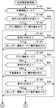
- FIG. 5 is a flowchart (part 1) illustrating a procedure of charge / discharge control processing according to the first embodiment.
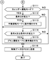
- 5 is a flowchart (part 2) illustrating a procedure of charge / discharge control processing according to the first embodiment.
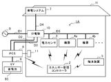
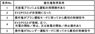
- FIG. 5 is a figure which shows the whole structure of the energy management system which concerns on Embodiment 2 of this invention. It is a figure which shows an example of the priority acquisition conditions in Embodiment 2.
- FIG. 1 is a diagram showing an overall configuration of an energy management system 1 according to Embodiment 1 of the present invention.
- the energy management system 1 is a so-called HEMS (Home Energy Management System) that manages electric power used in a general household.
- the energy management system 1 includes an energy management controller 2, a power sensor 3, a plurality of devices 4 (devices 4 a, 4 b,...), A terminal device 5, a PCS 6, and a power generation system 7.
- the power sensor 3 measures the amount of power consumed in this home (demand area).
- the power sensor 3 is communicably connected to the energy management controller 2 via a wireless network (not shown) constructed in the house H.
- This wireless network is, for example, a network conforming to ECHONET Lite.
- the power sensor 3 transmits data regarding the measured power amount to the energy management controller 2.
- the device 4 (devices 4a, 4b,...) Is an electrical device installed in the house H such as an illuminator, an air conditioner, a refrigerator, an IH cooking heater, a rice cooker, a microwave oven, a floor heating system, and the like. Each device 4 is connected to a power line D5 that supplies power from the commercial power source 9 or the like. Each device 4 is communicably connected to the energy management controller 2 via the wireless network (not shown).
- PCS6 is a power conditioning system for EV (electric vehicle) 8.
- the PCS 6 charges and discharges the storage battery 80 mounted on the EV 8.
- the PCS 6 is supplied with power from the commercial power supply 9 and the like via the power line D1, the distribution board 10, and the power line D2.
- the PCS 6 supplies power from the commercial power supply 9 or the like to the storage battery 80 when the storage battery 80 is charged. Further, the PCS 6 supplies power from the storage battery 80 to the distribution board 10 via the power line D3 when the storage battery 80 is discharged.
- the PCS 6 is communicably connected to the energy management controller 2 via the above-described wireless network. Note that communication between the PCS 6 and the energy management controller 2 may be performed via a LAN cable.
- the power generation system 7 includes a photovoltaic power generation panel (PV panel) and a power conditioner, although not shown in the figure.
- the power generation system 7 converts electricity generated by the PV panel from DC power to AC power by a power conditioner, and supplies it to the distribution board 10 via the power line D4.
- the terminal device 5 is a portable communication device having a display function, and is, for example, a tablet personal computer or a smartphone.
- the terminal device 5 performs data communication with the energy management controller 2 in accordance with a well-known wireless LAN standard such as Wi-Fi (registered trademark).
- the terminal device 5 functions as an interface (user interface) between the energy management system 1 and a user who is a resident of the house H.
- the energy management controller 2 is installed at an appropriate location in the house H, and monitors power consumption in this home.
- the energy management controller 2 performs operation control of each device 4 and monitoring of the operation state. Furthermore, the energy management controller 2 controls charging and discharging of the storage battery 80 via the PCS 6.
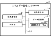
- the energy management controller 2 includes a device communication unit 20 for communicating with each device 4 and the like, a terminal communication unit 21 for communicating with the terminal device 5, and a program and data for holding The data storage part 22 and the control part 23 which controls these are provided.
- Each component of the energy management controller 2 is connected to each other via a bus 24.
- the device communication unit 20 includes a communication interface such as a wireless LAN card, for example, is connected to the above-described wireless network, and performs wireless data communication with the power sensor 3, each device 4, and the PCS 6 under the control of the control unit 23.
- a communication interface such as a wireless LAN card, for example, is connected to the above-described wireless network, and performs wireless data communication with the power sensor 3, each device 4, and the PCS 6 under the control of the control unit 23.
- the terminal communication unit 21 is provided with a predetermined short-range wireless communication interface, and conforms to the terminal device 5 and a well-known wireless LAN standard such as Wi-Fi (registered trademark) under the control of the control unit 23. Perform data communication.
- a well-known wireless LAN standard such as Wi-Fi (registered trademark)
- the data storage unit 22 is composed of, for example, a readable / writable nonvolatile semiconductor memory such as a flash memory.
- the data storage unit 22 stores a transition condition table 220 described later.
- the data storage part 22 memorize
- the data storage unit 22 stores a program for monitoring the power consumption in the home, a program for controlling the operation of each device 4, and data used when these programs are executed.
- the control unit 23 includes a CPU (Central Processing Unit), a ROM (Read Only Memory), a RAM (Random Access Memory), and the like (all not shown), and controls the energy management controller 2 in an integrated manner. As shown in FIG. 3, the control unit 23 includes a user interface processing unit 230, an operation right giving unit 231, and a charge / discharge control unit 232 as functions unique to the present invention. The functions of these components are realized by a CPU or the like executing a charge / discharge control program stored in the data storage unit 22.
- the user interface processing unit 230 performs user interface processing via the terminal device 5. That is, the user interface processing unit 230 receives an operation from the user via the terminal device 5 and performs a process according to the content of the received operation. In addition, the user interface processing unit 230 performs processing for transmitting information (for example, monitoring screen data) to be presented to the user to the terminal device 5 and displaying the information on the terminal unit 5.
- information for example, monitoring screen data
- the operation right granting unit 231 determines the operation mode to which the operation right should be next given based on the transition condition table 220, and gives the operation right to the determined operation mode.
- the operation right is a right to operate the PCS 6, and only the control command in the operation mode to which the operation right is given is transmitted to the PCS 6.
- the operation mode refers to a processing mode in charge / discharge control of the storage battery 80, and there are three modes: a manual operation mode, a plan operation mode, and a calendar operation mode.
- charging / discharging control of the storage battery 80 is performed based on a user operation via the terminal device 5.
- the operation in this case includes, for example, an operation for instructing start / stop of charging of the storage battery 80 and start / stop of discharge.
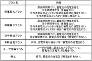
- charge / discharge control of the storage battery 80 is performed according to one charge / discharge plan preset by the user among the plurality of charge / discharge plans.
- An example of the charge / discharge plan is shown in FIG.
- “midnight time zone” refers to a time zone in which the electricity rate is cheaper in an electricity rate plan provided by an electric power company.
- the “daytime time zone” means a time zone other than the “midnight time zone”.
- the calendar registration function is a function capable of controlling the operation of the corresponding device 4 or charging the storage battery 80 based on the event registered in advance by the user and the start time of the event.
- “outing (with EV)”, “outing (without EV)”, “going home”, and the like are included in the event.
- the energy management controller 2 controls the PCS 6 so that the charging of the storage battery 80 is completed by 10:00 am To do.
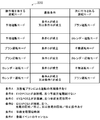
- FIG. 5 shows the contents of the transition condition table 220 in this embodiment.
- the transition condition table 220 a plurality of records in which an operation mode having an operation right, a transition condition, and an operation mode to which an operation right is to be given next when the transition condition is satisfied are registered. Data table.
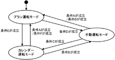
- transition condition table 220 shown in FIG. 5 for example, when there is an operation right in the manual operation mode at present, it is indicated that the operation right shifts to the plan operation mode when the condition A or the condition B is established.
- the condition A indicates that the user performs an operation for instructing the resumption of the operation according to the above-described charge / discharge plan
- the condition B is a state where the EV 8 is not connected to the PCS 6 and is not a pre-charging period.
- the pre-charging period refers to the charging period of the storage battery 80 in the calendar operation mode described above.
- the transition condition table 220 shown in FIG. 5 indicates that the operation right shifts to the calendar operation mode when the condition C is satisfied.
- the condition C indicates that the EV 8 is not connected to the PCS 6 and is in the precharge period.
- the operation right when there is an operation right in the plan operation mode, the operation right is shifted to the manual operation mode when the condition D is satisfied, and the operation right is set to the calendar operation mode when the condition E is satisfied.
- the condition D is that the EV 8 is connected to the PCS 6 and the user performs an operation to start / stop charging or start / stop discharging the storage battery 80 via the terminal device 5. It shows that it was broken.
- Condition E indicates that the current time is the precharge start time.
- the precharge start time refers to a time at which charging of the storage battery 80 is started in the charge control according to the calendar operation mode described above.
- the operation right when the operation right is present in the calendar operation mode, the operation right is shifted to the manual operation mode when the condition D is satisfied, and the operation right is shifted to the plan operation mode when the condition A or the condition F is satisfied.
- the condition F indicates that the registered event is canceled (including a change) by the user in the calendar registration function described above.
- FIG. 6 schematically shows the contents of the transition condition table 220 shown in FIG.
- the charge / discharge control unit 232 performs charge / discharge control of the storage battery 80 via the PCS 6 in accordance with any one operation mode having an operation right among the manual operation mode, the plan operation mode, and the calendar operation mode.
- FIG. 7 and 8 are flowcharts showing a procedure of processing (charging / discharging control processing) for controlling charging / discharging of the storage battery 80, which is executed by the control unit 23 of the energy management controller 2.
- FIG. This charge / discharge control process is repeatedly executed at a predetermined cycle.
- the operation right granting unit 231 determines the operation mode to which the operation right is currently given. As a result, when there is an operation right in the manual mode (step S101; YES), the operation right giving unit 231 determines whether or not the condition A or the condition B in the transition condition table 220 is satisfied (step S102). When the condition A or the condition B is satisfied (step S102; YES), the operation right giving unit 231 deprives the operation right from the manual operation mode and gives the operation right to the plan operation mode (step S103). Thereafter, the control unit 23 proceeds to the process of step S116.
- step S104 determines whether or not the condition C in the transition condition table 220 is satisfied.
- step S104 determines whether or not the condition C in the transition condition table 220 is satisfied.
- step S105 the condition C is satisfied (step S104; YES)
- step S105 the control unit 23 proceeds to the process of step S116.
- step S106 When there is an operation right in the plan operation mode (step S106; YES), the operation right giving unit 231 determines whether or not the condition D in the transition condition table 220 is satisfied (step S107). When the condition D is satisfied (step S107; YES), the operation right giving unit 231 deprives the operation right from the plan operation mode and gives the operation right to the manual operation mode (step S108). Thereafter, the control unit 23 proceeds to the process of step S116.
- step S109 determines whether or not the condition E in the transition condition table 220 is satisfied.
- step S109 determines whether or not the condition E in the transition condition table 220 is satisfied.
- step S110 the operation right giving unit 231 deprives the operation right from the plan operation mode and gives the operation right to the calendar operation mode. Thereafter, the control unit 23 proceeds to the process of step S116.
- step S111 in FIG. 8 When there is an operation right in the calendar operation mode (step S111 in FIG. 8; YES), the operation right giving unit 231 determines whether or not the condition D in the transition condition table 220 is satisfied (step S112). When the condition D is satisfied (step S112; YES), the operation right giving unit 231 removes the operation right from the calendar operation mode and gives the operation right to the manual operation mode (step S113). Thereafter, the control unit 23 proceeds to the process of step S116.
- step S112 determines whether or not the condition A or the condition F in the transition condition table 220 is satisfied (step S114).
- step S114 the condition A or the condition F is satisfied (step S114; YES)
- step S115 the operation right giving unit 231 deprives the operation right from the calendar operation mode and gives the operation right to the plan operation mode (step S115).
- step S116 the charge / discharge control unit 232 controls the charge / discharge of the storage battery 80 via the PCS 6 according to the operation mode having the operation right. Specifically, data (control data) indicating a control command according to the operation mode having the operation right is transmitted to the PCS 6.
- charge / discharge control of the storage battery 80 mounted on the EV 8 is performed by the energy management controller 2 corresponding to a so-called HEMS controller.
- the energy management controller 2 is not only the control (manual operation mode) according to the instruction
- Perform control plan operation mode, calendar operation mode). For this reason, charging / discharging of the storage battery 80 of EV8 can be appropriately performed corresponding to the life scene of the user who lives in the house H. Therefore, the storage battery 80 can be used efficiently and user convenience is improved.
- the energy management controller 2 performs charge / discharge control according to the operation mode having the operation right so that the control by the plurality of operation modes does not compete, and the operation right is assigned to the next based on the transition condition table 220.
- the operation mode having the operation right that is, the method of charging / discharging control of the storage battery 80 can be switched appropriately and smoothly, and charging / discharging of the storage battery 80 can be efficiently performed in accordance with user needs. it can.
- control unit 23 may be configured to have a function in which the operation right granting unit 231 and the charge / discharge control unit 232 are integrated. That is, the charge / discharge control unit 232 discriminates the operation mode in which the right to operate the PCS 6 is to be next granted based on the transition condition table 220 in the same manner as the operation right grant unit 231 described above. You may perform charge / discharge control of the storage battery 80 via PCS6 according to a mode.
- Embodiment 2 (Embodiment 2) Then, the energy management system which concerns on Embodiment 2 of this invention is demonstrated.
- components and the like that are common to the first embodiment are denoted by the same reference numerals, and description thereof is omitted.
- FIG. 9 is a diagram showing an overall configuration of the energy management system 1A of the second embodiment.
- a PCS remote controller 11 connected to the PCS 6 via a communication line is newly added to the configuration of the energy management system 1 of the first embodiment.
- the PCS remote controller 11 is a remote controller for the user to operate the PCS 6.
- the PCS remote controller 11 includes an input device such as a touch panel and a touch pad, a display device such as a full-dot LCD (Liquid Crystal Display) panel, and a microcomputer.
- the user can operate the PCS remote controller 11 to instruct the PCS 6 to start / stop charging the storage battery 80 or start / stop discharging. Further, the user can cause the PCS remote controller 11 to execute the selected automatic control by operating the PCS remote controller 11 and selecting a desired automatic control from among a plurality of automatic controls.
- charge / discharge control of the storage battery 80 is performed not only by the energy management controller 2 but also by the PCS remote controller 11 via the PCS 6. For this reason, the device for eliminating the inconvenience (for example, the fall of charging / discharging efficiency etc.) which arises when both control competes is needed.
- the PCS 6 accepts a control command from the one that has acquired the right to operate the PCS 6 out of the two controllers, the PCS remote controller 11 and the energy management controller 2,
- the specification is set in advance so as not to accept a control command from a person who has not acquired priority.
- the PCS remote controller 11 and the energy management controller 2 each acquire priority according to a predetermined priority acquisition condition.
- the PCS remote control 11 uses the operation by the user as a priority acquisition condition. Specifically, when an operation by the user is performed, the PCS remote controller 11 determines that the priority acquisition condition is satisfied, and issues a priority acquisition notification to the PCS 6. More specifically, when the PCS remote controller 11 transmits control data based on the user's operation content to the PCS 6, the PCS remote controller 11 stores information indicating priority acquisition in the control data. The PCS 6 that has received such control data gives priority to the PCS remote controller 11 and performs charge / discharge control of the storage battery 80 in accordance with a control command indicated by the control data.
- the energy management controller 2 determines whether or not priority acquisition is necessary based on a plurality of priority acquisition conditions defined as shown in FIG.
- the control unit 23 of the energy management controller 2 repeatedly executes a process for determining whether or not priority acquisition is necessary (priority acquisition necessity determination process) at a predetermined cycle.
- the control unit 23 first executes the priority acquisition necessity determination process.
- control unit 23 determines whether or not each of the plurality of priority acquisition conditions defined as shown in FIG. When any priority acquisition condition is satisfied, the control unit 23 determines that priority acquisition is necessary.
- the control unit 23 When it is necessary to acquire priority, the control unit 23 issues a priority acquisition notification to the PCS 6. More specifically, the control unit 23 stores information indicating priority acquisition in the control data (see step S116 in FIG. 8) transmitted to the PSC 6. The PCS 6 that has received the control data gives priority to the energy management controller 2 and performs charge / discharge control of the storage battery 80 in accordance with a control command indicated by the control data.
- the two controllable controllers (PCS remote controller 11 and energy management controller 2) for the PCS 6 comply with a predetermined priority acquisition condition. Only the control command from the controller that has acquired the priority is accepted by the PCS 6. Therefore, it is possible to eliminate the inconvenience that occurs when the control commands from both controllers compete.
- the configuration of the energy management controller 2 includes an input device such as a keyboard, a mouse, a keypad, a touchpad, and a touch panel, and a display device such as a CRT display, a liquid crystal display, an organic EL display, and a plasma display. Also good. In this way, the user can directly input an operation related to charging / discharging of the storage battery 80 to the energy management controller 2.
- an input device such as a keyboard, a mouse, a keypad, a touchpad, and a touch panel
- a display device such as a CRT display, a liquid crystal display, an organic EL display, and a plasma display. Also good. In this way, the user can directly input an operation related to charging / discharging of the storage battery 80 to the energy management controller 2.
- the number of controllers that can be controlled with respect to the PCS 6 is the PCS remote controller 11 and the energy management controller 2. However, the number may be three or more.
- the energy management controller 2 and the PCS remote controller 11 are provided with a function for identifying the user, and in the process of assigning the operation right and the priority right as described above, the authority given in advance for each user (user authority) is also taken into account.
- the necessity or the like may be determined. Thereby, for example, it may be prohibited to cancel the operation of the upper user by the operation of the lower user.
- the program executed by the energy management controller 2 is a CD-ROM (Compact Disc Read Only Memory), DVD (Digital Versatile Disc), MO (Magneto-Optical Disk), USB memory, memory card. It is also possible to store and distribute in a computer-readable recording medium such as the above. Then, by installing such a program on a specific or general-purpose computer, the computer can function as the energy management controller 2 in each of the above embodiments.
- the above program may be stored in a disk device or the like included in a server device on a communication network such as the Internet, and may be downloaded onto a computer, for example, superimposed on a carrier wave.
- the above-described processing can also be achieved by starting and executing a program while transferring it via a communication network.
- the above-described processing can also be achieved by executing all or part of the program on the server device and executing the program while the computer transmits and receives information regarding the processing via the communication network.
- the present invention can be suitably employed in a system that manages electric power used in the home.
Landscapes
- Engineering & Computer Science (AREA)
- Power Engineering (AREA)
- Transportation (AREA)
- Mechanical Engineering (AREA)
- Life Sciences & Earth Sciences (AREA)
- Sustainable Development (AREA)
- Sustainable Energy (AREA)
- Charge And Discharge Circuits For Batteries Or The Like (AREA)
- Supply And Distribution Of Alternating Current (AREA)
- Remote Monitoring And Control Of Power-Distribution Networks (AREA)
Abstract
Description
複数の運転モードの内の操作権を有する運転モードに従って、電気自動車に搭載された蓄電池の充放電を行うパワーコンディショニングシステムを介した前記蓄電池の充放電制御を行う充放電制御部と、
予め定めた遷移条件に基づいて、前記操作権を次に付与すべき運転モードを判別し、判別した運転モードに前記操作権を付与する操作権付与部と、を備える。
図1は、本発明の実施形態1に係るエネルギー管理システム1の全体構成を示す図である。このエネルギー管理システム1は、一般家庭で使用される電力の管理を行う、いわゆる、HEMS(Home Energy Management System)と呼ばれるシステムである。エネルギー管理システム1は、エネルギー管理コントローラ2と、電力センサ3と、複数の機器4(機器4a,4b,…)と、端末装置5と、PCS6と、発電システム7と、を備える。
続いて、本発明の実施形態2に係るエネルギー管理システムについて説明する。なお、以下の説明において、実施形態1と共通する構成要素等については、同一の符号を付し、その説明を省略する。
Claims (14)
- 複数の運転モードの内の操作権を有する運転モードに従って、電気自動車に搭載された蓄電池の充放電を行うパワーコンディショニングシステムを介した前記蓄電池の充放電制御を行う充放電制御部と、
予め定めた遷移条件に基づいて、前記操作権を次に付与すべき運転モードを判別し、判別した運転モードに前記操作権を付与する操作権付与部と、を備える、エネルギー管理コントローラ。 - 前記複数の運転モードには、登録された充放電プランに従って前記蓄電池の充放電制御を行うプラン運転モードと、カレンダー登録機能を用いたユーザの登録内容に基づいて前記蓄電池の充放電制御を行うカレンダー運転モードと、ユーザの手動操作によって前記蓄電池の充放電制御を行う手動運転モードと、が含まれる、請求項1に記載のエネルギー管理コントローラ。
- 前記操作権付与部は、前記電気自動車と前記パワーコンディショニングシステムとが接続された状態で、ユーザにより前記蓄電池の充放電制御のための手動操作が行われた場合、前記手動運転モードに前記操作権を付与する、請求項2に記載のエネルギー管理コントローラ。
- 前記操作権付与部は、ユーザにより前記充放電プランによる運転の再開操作が行われた場合、ユーザにより前記カレンダー登録機能における登録済みのイベントがキャンセルされた場合、又は、前記電気自動車と前記パワーコンディショニングシステムとが接続されていない状態であって前記カレンダー運転モードにおける前記蓄電池の充電期間でない場合、前記プラン運転モードに前記操作権を付与する、請求項2又は3に記載のエネルギー管理コントローラ。
- 前記操作権付与部は、前記電気自動車と前記パワーコンディショニングシステムとが接続されていない状態であって前記カレンダー運転モードにおける前記蓄電池の充電期間中である場合、又は、現在時刻が前記カレンダー運転モードにおける前記蓄電池の充電開始時刻になった場合に、前記カレンダー運転モードに前記操作権を付与する、請求項2から4の何れか1項に記載のエネルギー管理コントローラ。
- 電気自動車に搭載された蓄電池の充放電を行うパワーコンディショニングシステムを介して前記蓄電池の充放電制御を行うエネルギー管理コントローラであって、
複数の運転モードに従って、前記パワーコンディショニングシステムを介した前記蓄電池の充放電制御を行う充放電制御部を備え、
前記複数の運転モードには、登録された充放電プランに従って前記蓄電池の充放電制御を行うプラン運転モードと、カレンダー登録機能を用いたユーザの登録内容に基づいて前記蓄電池の充放電制御を行うカレンダー運転モードと、ユーザの手動操作によって前記蓄電池の充放電制御を行う手動運転モードと、が含まれる、エネルギー管理コントローラ。 - 前記充放電制御部は、前記電気自動車と前記パワーコンディショニングシステムとが接続された状態で、ユーザにより前記蓄電池の充放電制御のための手動操作が行われた場合、前記手動運転モードに従って前記蓄電池の充放電制御を行う、請求項6に記載のエネルギー管理コントローラ。
- 前記充放電制御部は、ユーザにより前記充放電プランによる運転の再開操作が行われた場合、ユーザにより前記カレンダー登録機能における登録済みのイベントがキャンセルされた場合、又は、前記電気自動車と前記パワーコンディショニングシステムとが接続されていない状態であって前記カレンダー運転モードにおける前記蓄電池の充電期間でない場合、前記プラン運転モードに従って前記蓄電池の充放電制御を行う、請求項6又は7に記載のエネルギー管理コントローラ。
- 前記充放電制御部は、前記電気自動車と前記パワーコンディショニングシステムとが接続されていない状態であって前記カレンダー運転モードにおける前記蓄電池の充電期間中である場合、又は、現在時刻が前記カレンダー運転モードにおける前記蓄電池の充電開始時刻になった場合に、前記カレンダー運転モードに従って前記蓄電池の充放電制御を行う、請求項6から8の何れか1項に記載のエネルギー管理コントローラ。
- エネルギー管理コントローラと、電気自動車に搭載された蓄電池の充放電を行うパワーコンディショニングシステムと、を備えるエネルギー管理システムであって、
前記エネルギー管理コントローラは、
複数の運転モードの内の操作権を有する運転モードに従って、前記パワーコンディショニングシステムを介した前記蓄電池の充放電制御を行う充放電制御部と、
予め定めた遷移条件に基づいて、前記操作権を次に付与すべき運転モードを判別し、判別した運転モードに前記操作権を付与する操作権付与部と、を備える、エネルギー管理システム。 - 前記パワーコンディショニングシステムを介した前記蓄電池の充放電制御を行う第2のコントローラをさらに備え、
前記パワーコンディショニングシステムは、前記エネルギー管理コントローラと前記第2のコントローラの内、優先権を取得しているコントローラからの制御指令のみを受け付ける、請求項10に記載のエネルギー管理システム。 - 前記パワーコンディショニングシステムは、優先権の取得通知を受けると、通知元のコントローラに対して前記優先権を付与し、
前記エネルギー管理コントローラ及び前記第2のコントローラは、それぞれ予め定めた優先権を取得するための条件が成立すると、前記パワーコンディショニングシステムに対して前記優先権の取得通知を発行する、請求項11に記載のエネルギー管理システム。 - 操作権付与部が、予め定めた遷移条件に基づいて、複数の運転モードの内から操作権を次に付与すべき運転モードを判別し、判別した運転モードに前記操作権を付与し、
充放電制御部が、前記操作権を有する運転モードに従って、電気自動車に搭載された蓄電池の充放電を行うパワーコンディショニングシステムを介した前記蓄電池の充放電制御を行う、充放電制御方法。 - コンピュータを、
複数の運転モードの内の操作権を有する運転モードに従って、電気自動車に搭載された蓄電池の充放電を行うパワーコンディショニングシステムを介した前記蓄電池の充放電制御を行う充放電制御部、
予め定めた遷移条件に基づいて、前記操作権を次に付与すべき運転モードを判別し、判別した運転モードに前記操作権を付与する操作権付与部、として機能させるためのプログラム。
Priority Applications (5)
| Application Number | Priority Date | Filing Date | Title |
|---|---|---|---|
| CN201480078086.8A CN106233563A (zh) | 2014-04-18 | 2014-04-18 | 能量管理控制器、能量管理系统、充放电控制方法以及程序 |
| EP14889215.1A EP3133712B1 (en) | 2014-04-18 | 2014-04-18 | Energy management controller, energy management system, charge/discharge control method and program |
| PCT/JP2014/061018 WO2015159421A1 (ja) | 2014-04-18 | 2014-04-18 | エネルギー管理コントローラ、エネルギー管理システム、充放電制御方法及びプログラム |
| JP2016513592A JP6261721B2 (ja) | 2014-04-18 | 2014-04-18 | エネルギー管理システム |
| US15/121,852 US10259335B2 (en) | 2014-04-18 | 2014-04-18 | Energy management controller, energy management system, charge/discharge control method and program |
Applications Claiming Priority (1)
| Application Number | Priority Date | Filing Date | Title |
|---|---|---|---|
| PCT/JP2014/061018 WO2015159421A1 (ja) | 2014-04-18 | 2014-04-18 | エネルギー管理コントローラ、エネルギー管理システム、充放電制御方法及びプログラム |
Publications (1)
| Publication Number | Publication Date |
|---|---|
| WO2015159421A1 true WO2015159421A1 (ja) | 2015-10-22 |
Family
ID=54323661
Family Applications (1)
| Application Number | Title | Priority Date | Filing Date |
|---|---|---|---|
| PCT/JP2014/061018 Ceased WO2015159421A1 (ja) | 2014-04-18 | 2014-04-18 | エネルギー管理コントローラ、エネルギー管理システム、充放電制御方法及びプログラム |
Country Status (5)
| Country | Link |
|---|---|
| US (1) | US10259335B2 (ja) |
| EP (1) | EP3133712B1 (ja) |
| JP (1) | JP6261721B2 (ja) |
| CN (1) | CN106233563A (ja) |
| WO (1) | WO2015159421A1 (ja) |
Cited By (3)
| Publication number | Priority date | Publication date | Assignee | Title |
|---|---|---|---|---|
| FR3058601A1 (fr) * | 2016-11-08 | 2018-05-11 | Luca Rossini | Installation photovoltaique de site industriel avec dispositif de stockage de l’energie sur des chariots de manutention |
| CN109066745A (zh) * | 2018-08-09 | 2018-12-21 | 蔚来汽车有限公司 | 电储能系统及其运行控制方法、装置、系统 |
| JP2021022984A (ja) * | 2019-07-25 | 2021-02-18 | シャープ株式会社 | 制御システム、被制御装置および被制御装置の制御方法 |
Families Citing this family (7)
| Publication number | Priority date | Publication date | Assignee | Title |
|---|---|---|---|---|
| JP6897495B2 (ja) * | 2017-10-27 | 2021-06-30 | トヨタ自動車株式会社 | 配車システム及び配車方法 |
| EP3680125A1 (de) | 2019-01-10 | 2020-07-15 | FRONIUS INTERNATIONAL GmbH | Verfahren und vorrichtung zum laden eines elektrofahrzeuges |
| EP3689667A1 (en) * | 2019-01-30 | 2020-08-05 | Green Motion SA | Electrical vehicle charging station with power management |
| US11135936B2 (en) * | 2019-03-06 | 2021-10-05 | Fermata, LLC | Methods for using temperature data to protect electric vehicle battery health during use of bidirectional charger |
| CN109849713A (zh) * | 2019-03-25 | 2019-06-07 | 南京微晟电源科技有限公司 | 一种储能充电桩系统 |
| CN109910669B (zh) * | 2019-04-29 | 2021-01-15 | 恒大智慧充电科技有限公司 | 充电调控方法、计算机设备及存储介质 |
| US11888340B2 (en) * | 2020-12-04 | 2024-01-30 | Schneider Electric It Corporation | Method to enhance the life of a lithium battery |
Citations (3)
| Publication number | Priority date | Publication date | Assignee | Title |
|---|---|---|---|---|
| JP2008054439A (ja) * | 2006-08-25 | 2008-03-06 | Toyota Motor Corp | 電力システム |
| JP2009284586A (ja) * | 2008-05-20 | 2009-12-03 | Nippon Telegr & Teleph Corp <Ntt> | 電力システムおよびその制御方法 |
| WO2014002205A1 (ja) * | 2012-06-27 | 2014-01-03 | 三菱電機株式会社 | 電動車両の充電制御装置 |
Family Cites Families (19)
| Publication number | Priority date | Publication date | Assignee | Title |
|---|---|---|---|---|
| JP5026027B2 (ja) * | 2006-08-29 | 2012-09-12 | ヤマザキマザック株式会社 | レーザ加工機の自動工具交換装置 |
| US8872379B2 (en) * | 2007-11-30 | 2014-10-28 | Johnson Controls Technology Company | Efficient usage, storage, and sharing of energy in buildings, vehicles, and equipment |
| US20100017045A1 (en) * | 2007-11-30 | 2010-01-21 | Johnson Controls Technology Company | Electrical demand response using energy storage in vehicles and buildings |
| US9853488B2 (en) * | 2008-07-11 | 2017-12-26 | Charge Fusion Technologies, Llc | Systems and methods for electric vehicle charging and power management |
| US20100094496A1 (en) * | 2008-09-19 | 2010-04-15 | Barak Hershkovitz | System and Method for Operating an Electric Vehicle |
| JP4713623B2 (ja) * | 2008-09-25 | 2011-06-29 | 株式会社日立製作所 | 充放電管理装置 |
| US20110258112A1 (en) | 2008-10-31 | 2011-10-20 | Leviton Manufacturing Company Inc. | System and method for charging a vehicle |
| JP2010154646A (ja) | 2008-12-25 | 2010-07-08 | Omron Corp | 充電制御装置および方法、並びに、プログラム |
| JP2011151896A (ja) | 2010-01-19 | 2011-08-04 | Toshiba Corp | 充放電制御装置 |
| US9299093B2 (en) * | 2010-01-29 | 2016-03-29 | GM Global Technology Operations LLC | Method for charging a plug-in electric vehicle |
| JP5498193B2 (ja) | 2010-02-12 | 2014-05-21 | 本田技研工業株式会社 | 車両充電電力マネジメントシステム |
| WO2011156776A2 (en) * | 2010-06-10 | 2011-12-15 | The Regents Of The University Of California | Smart electric vehicle (ev) charging and grid integration apparatus and methods |
| JP5782233B2 (ja) * | 2010-06-14 | 2015-09-24 | 大和ハウス工業株式会社 | エネルギーマネジメントシステム及びエネルギーマネジメント方法 |
| US20120249065A1 (en) * | 2011-04-01 | 2012-10-04 | Michael Bissonette | Multi-use energy management and conversion system including electric vehicle charging |
| WO2012134495A1 (en) * | 2011-04-01 | 2012-10-04 | Aerovironment, Inc. | Multi-use energy management and conversion system including electric vehicle charging |
| JP5857646B2 (ja) * | 2011-11-10 | 2016-02-10 | ソニー株式会社 | 電力管理装置、電力管理方法およびデマンド通知装置 |
| US9494625B2 (en) * | 2011-11-11 | 2016-11-15 | Sharp Kabushiki Kaisha | Power management device, method of controlling power management device, and program for controlling power management device |
| JP2013183588A (ja) | 2012-03-02 | 2013-09-12 | Sharp Corp | 電気車両の充放電装置、充放電制御プログラムおよび記録媒体 |
| JP2014103717A (ja) * | 2012-11-16 | 2014-06-05 | Toshiba Corp | 充放電指示装置、充放電システム、充放電管理方法ならびにプログラム |
-
2014
- 2014-04-18 JP JP2016513592A patent/JP6261721B2/ja not_active Expired - Fee Related
- 2014-04-18 WO PCT/JP2014/061018 patent/WO2015159421A1/ja not_active Ceased
- 2014-04-18 EP EP14889215.1A patent/EP3133712B1/en not_active Not-in-force
- 2014-04-18 US US15/121,852 patent/US10259335B2/en active Active
- 2014-04-18 CN CN201480078086.8A patent/CN106233563A/zh active Pending
Patent Citations (3)
| Publication number | Priority date | Publication date | Assignee | Title |
|---|---|---|---|---|
| JP2008054439A (ja) * | 2006-08-25 | 2008-03-06 | Toyota Motor Corp | 電力システム |
| JP2009284586A (ja) * | 2008-05-20 | 2009-12-03 | Nippon Telegr & Teleph Corp <Ntt> | 電力システムおよびその制御方法 |
| WO2014002205A1 (ja) * | 2012-06-27 | 2014-01-03 | 三菱電機株式会社 | 電動車両の充電制御装置 |
Non-Patent Citations (1)
| Title |
|---|
| See also references of EP3133712A4 * |
Cited By (6)
| Publication number | Priority date | Publication date | Assignee | Title |
|---|---|---|---|---|
| FR3058601A1 (fr) * | 2016-11-08 | 2018-05-11 | Luca Rossini | Installation photovoltaique de site industriel avec dispositif de stockage de l’energie sur des chariots de manutention |
| FR3058600A1 (fr) * | 2016-11-08 | 2018-05-11 | Luca Rossini | Installation photovoltaique de site industriel avec dispositif de stockage de l'energie sur des chariots de manutention |
| CN109066745A (zh) * | 2018-08-09 | 2018-12-21 | 蔚来汽车有限公司 | 电储能系统及其运行控制方法、装置、系统 |
| CN109066745B (zh) * | 2018-08-09 | 2022-03-15 | 蔚来(安徽)控股有限公司 | 电储能系统及其运行控制方法、装置、系统 |
| JP2021022984A (ja) * | 2019-07-25 | 2021-02-18 | シャープ株式会社 | 制御システム、被制御装置および被制御装置の制御方法 |
| JP7319854B2 (ja) | 2019-07-25 | 2023-08-02 | シャープ株式会社 | 制御システム、被制御装置および被制御装置の制御方法 |
Also Published As
| Publication number | Publication date |
|---|---|
| JP6261721B2 (ja) | 2018-01-17 |
| JPWO2015159421A1 (ja) | 2017-04-13 |
| EP3133712A4 (en) | 2018-01-10 |
| US10259335B2 (en) | 2019-04-16 |
| EP3133712B1 (en) | 2020-09-02 |
| EP3133712A1 (en) | 2017-02-22 |
| US20170008416A1 (en) | 2017-01-12 |
| CN106233563A (zh) | 2016-12-14 |
Similar Documents
| Publication | Publication Date | Title |
|---|---|---|
| JP6261721B2 (ja) | エネルギー管理システム | |
| JP5900249B2 (ja) | 電力供給システム | |
| JP6198970B2 (ja) | 制御装置、機器制御システム、機器制御方法及びプログラム | |
| JP5518419B2 (ja) | 給電管理装置 | |
| US20140316599A1 (en) | Consumer energy management system and consumer energy management method | |
| JP6430041B2 (ja) | 管理装置、及び、制御方法 | |
| JP6161822B2 (ja) | エネルギー管理コントローラ、エネルギー管理方法及びプログラム | |
| JP6391788B2 (ja) | 電力計測装置、抑制レベル通知方法及びプログラム | |
| US9651972B2 (en) | Demand regulating system, demand regulating apparatus, and consumption device management apparatus | |
| JP6671479B2 (ja) | 電気機器、消費電力削減システム、通信アダプタ及び消費電力削減方法 | |
| WO2015079493A1 (ja) | エネルギー管理システム、電力計測装置、負荷機器、通信アダプタ、システムコントローラ、エネルギー管理方法及びプログラム | |
| JP6373513B2 (ja) | 制御装置、充電情報表示方法及びプログラム | |
| JP6261755B2 (ja) | 制御装置、機器制御方法及びプログラム | |
| US20170324245A1 (en) | Power control apparatus, power control method, and power control program | |
| US20160241033A1 (en) | Control device, control method, and program | |
| JP2018113605A (ja) | 機器制御装置 | |
| JP6075584B2 (ja) | 制御装置、エネルギーマネジメントシステム、制御方法、および、プログラム | |
| KR102046822B1 (ko) | 솔라셀을 이용한 발전 전력의 이용 관리 장치 | |
| JP6698365B2 (ja) | 電力調整システム、電気機器、通信アダプタ、電力調整方法及びプログラム | |
| JP6631870B2 (ja) | 電力管理システム、電力管理装置、電力管理方法、及び、プログラム | |
| JP6385599B2 (ja) | エネルギー管理装置、電力情報表示方法及びプログラム | |
| JP6406120B2 (ja) | 抑制判定装置 |
Legal Events
| Date | Code | Title | Description |
|---|---|---|---|
| 121 | Ep: the epo has been informed by wipo that ep was designated in this application |
Ref document number: 14889215 Country of ref document: EP Kind code of ref document: A1 |
|
| ENP | Entry into the national phase |
Ref document number: 2016513592 Country of ref document: JP Kind code of ref document: A |
|
| WWE | Wipo information: entry into national phase |
Ref document number: 15121852 Country of ref document: US |
|
| NENP | Non-entry into the national phase |
Ref country code: DE |
|
| REEP | Request for entry into the european phase |
Ref document number: 2014889215 Country of ref document: EP |
|
| WWE | Wipo information: entry into national phase |
Ref document number: 2014889215 Country of ref document: EP |