WO2015159555A1 - リソース管理システム - Google Patents
リソース管理システム Download PDFInfo
- Publication number
- WO2015159555A1 WO2015159555A1 PCT/JP2015/002127 JP2015002127W WO2015159555A1 WO 2015159555 A1 WO2015159555 A1 WO 2015159555A1 JP 2015002127 W JP2015002127 W JP 2015002127W WO 2015159555 A1 WO2015159555 A1 WO 2015159555A1
- Authority
- WO
- WIPO (PCT)
- Prior art keywords
- resource
- opening
- closing
- manager
- policy
- Prior art date
- Legal status (The legal status is an assumption and is not a legal conclusion. Google has not performed a legal analysis and makes no representation as to the accuracy of the status listed.)
- Ceased
Links
Images


Classifications
-
- H—ELECTRICITY
- H02—GENERATION; CONVERSION OR DISTRIBUTION OF ELECTRIC POWER
- H02J—ELECTRIC POWER NETWORKS; CIRCUIT ARRANGEMENTS OR SYSTEMS FOR SUPPLYING OR DISTRIBUTING ELECTRIC POWER; SYSTEMS FOR STORING ELECTRIC ENERGY
- H02J9/00—Circuit arrangements for emergency or stand-by power supply, e.g. for emergency lighting
- H02J9/04—Circuit arrangements for emergency or stand-by power supply, e.g. for emergency lighting in which the distribution system is disconnected from the normal source and connected to a standby source
- H02J9/06—Circuit arrangements for emergency or stand-by power supply, e.g. for emergency lighting in which the distribution system is disconnected from the normal source and connected to a standby source with automatic change-over, e.g. UPS systems
- H02J9/061—Circuit arrangements for emergency or stand-by power supply, e.g. for emergency lighting in which the distribution system is disconnected from the normal source and connected to a standby source with automatic change-over, e.g. UPS systems for DC powered loads
-
- H—ELECTRICITY
- H02—GENERATION; CONVERSION OR DISTRIBUTION OF ELECTRIC POWER
- H02J—ELECTRIC POWER NETWORKS; CIRCUIT ARRANGEMENTS OR SYSTEMS FOR SUPPLYING OR DISTRIBUTING ELECTRIC POWER; SYSTEMS FOR STORING ELECTRIC ENERGY
- H02J13/00—Circuit arrangements for providing remote monitoring or remote control of equipment in a power distribution network
- H02J13/12—Monitoring network conditions, e.g. electrical magnitudes or operational status
-
- H—ELECTRICITY
- H02—GENERATION; CONVERSION OR DISTRIBUTION OF ELECTRIC POWER
- H02J—ELECTRIC POWER NETWORKS; CIRCUIT ARRANGEMENTS OR SYSTEMS FOR SUPPLYING OR DISTRIBUTING ELECTRIC POWER; SYSTEMS FOR STORING ELECTRIC ENERGY
- H02J13/00—Circuit arrangements for providing remote monitoring or remote control of equipment in a power distribution network
- H02J13/13—Circuit arrangements for providing remote monitoring or remote control of equipment in a power distribution network characterised by the transmission of data to equipment in the power network
- H02J13/1331—Circuit arrangements for providing remote monitoring or remote control of equipment in a power distribution network characterised by the transmission of data to equipment in the power network using wireless data transmission
-
- G—PHYSICS
- G06—COMPUTING OR CALCULATING; COUNTING
- G06F—ELECTRIC DIGITAL DATA PROCESSING
- G06F1/00—Details not covered by groups G06F3/00 - G06F13/00 and G06F21/00
- G06F1/26—Power supply means, e.g. regulation thereof
-
- H—ELECTRICITY
- H02—GENERATION; CONVERSION OR DISTRIBUTION OF ELECTRIC POWER
- H02J—ELECTRIC POWER NETWORKS; CIRCUIT ARRANGEMENTS OR SYSTEMS FOR SUPPLYING OR DISTRIBUTING ELECTRIC POWER; SYSTEMS FOR STORING ELECTRIC ENERGY
- H02J13/00—Circuit arrangements for providing remote monitoring or remote control of equipment in a power distribution network
- H02J13/13—Circuit arrangements for providing remote monitoring or remote control of equipment in a power distribution network characterised by the transmission of data to equipment in the power network
- H02J13/1337—Circuit arrangements for providing remote monitoring or remote control of equipment in a power distribution network characterised by the transmission of data to equipment in the power network involving the use of Internet protocols
-
- H—ELECTRICITY
- H02—GENERATION; CONVERSION OR DISTRIBUTION OF ELECTRIC POWER
- H02J—ELECTRIC POWER NETWORKS; CIRCUIT ARRANGEMENTS OR SYSTEMS FOR SUPPLYING OR DISTRIBUTING ELECTRIC POWER; SYSTEMS FOR STORING ELECTRIC ENERGY
- H02J3/00—Circuit arrangements for AC mains or AC distribution networks
-
- Y—GENERAL TAGGING OF NEW TECHNOLOGICAL DEVELOPMENTS; GENERAL TAGGING OF CROSS-SECTIONAL TECHNOLOGIES SPANNING OVER SEVERAL SECTIONS OF THE IPC; TECHNICAL SUBJECTS COVERED BY FORMER USPC CROSS-REFERENCE ART COLLECTIONS [XRACs] AND DIGESTS
- Y02—TECHNOLOGIES OR APPLICATIONS FOR MITIGATION OR ADAPTATION AGAINST CLIMATE CHANGE
- Y02B—CLIMATE CHANGE MITIGATION TECHNOLOGIES RELATED TO BUILDINGS, e.g. HOUSING, HOUSE APPLIANCES OR RELATED END-USER APPLICATIONS
- Y02B70/00—Technologies for an efficient end-user side electric power management and consumption
- Y02B70/30—Systems integrating technologies related to power network operation and communication or information technologies for improving the carbon footprint of the management of residential or tertiary loads, i.e. smart grids as climate change mitigation technology in the buildings sector, including also the last stages of power distribution and the control, monitoring or operating management systems at local level
-
- Y—GENERAL TAGGING OF NEW TECHNOLOGICAL DEVELOPMENTS; GENERAL TAGGING OF CROSS-SECTIONAL TECHNOLOGIES SPANNING OVER SEVERAL SECTIONS OF THE IPC; TECHNICAL SUBJECTS COVERED BY FORMER USPC CROSS-REFERENCE ART COLLECTIONS [XRACs] AND DIGESTS
- Y02—TECHNOLOGIES OR APPLICATIONS FOR MITIGATION OR ADAPTATION AGAINST CLIMATE CHANGE
- Y02B—CLIMATE CHANGE MITIGATION TECHNOLOGIES RELATED TO BUILDINGS, e.g. HOUSING, HOUSE APPLIANCES OR RELATED END-USER APPLICATIONS
- Y02B90/00—Enabling technologies or technologies with a potential or indirect contribution to GHG emissions mitigation
- Y02B90/20—Smart grids as enabling technology in buildings sector
-
- Y—GENERAL TAGGING OF NEW TECHNOLOGICAL DEVELOPMENTS; GENERAL TAGGING OF CROSS-SECTIONAL TECHNOLOGIES SPANNING OVER SEVERAL SECTIONS OF THE IPC; TECHNICAL SUBJECTS COVERED BY FORMER USPC CROSS-REFERENCE ART COLLECTIONS [XRACs] AND DIGESTS
- Y02—TECHNOLOGIES OR APPLICATIONS FOR MITIGATION OR ADAPTATION AGAINST CLIMATE CHANGE
- Y02E—REDUCTION OF GREENHOUSE GAS [GHG] EMISSIONS, RELATED TO ENERGY GENERATION, TRANSMISSION OR DISTRIBUTION
- Y02E60/00—Enabling technologies; Technologies with a potential or indirect contribution to GHG emissions mitigation
-
- Y—GENERAL TAGGING OF NEW TECHNOLOGICAL DEVELOPMENTS; GENERAL TAGGING OF CROSS-SECTIONAL TECHNOLOGIES SPANNING OVER SEVERAL SECTIONS OF THE IPC; TECHNICAL SUBJECTS COVERED BY FORMER USPC CROSS-REFERENCE ART COLLECTIONS [XRACs] AND DIGESTS
- Y04—INFORMATION OR COMMUNICATION TECHNOLOGIES HAVING AN IMPACT ON OTHER TECHNOLOGY AREAS
- Y04S—SYSTEMS INTEGRATING TECHNOLOGIES RELATED TO POWER NETWORK OPERATION, COMMUNICATION OR INFORMATION TECHNOLOGIES FOR IMPROVING THE ELECTRICAL POWER GENERATION, TRANSMISSION, DISTRIBUTION, MANAGEMENT OR USAGE, i.e. SMART GRIDS
- Y04S10/00—Systems supporting electrical power generation, transmission or distribution
- Y04S10/30—State monitoring, e.g. fault, temperature monitoring, insulator monitoring, corona discharge
-
- Y—GENERAL TAGGING OF NEW TECHNOLOGICAL DEVELOPMENTS; GENERAL TAGGING OF CROSS-SECTIONAL TECHNOLOGIES SPANNING OVER SEVERAL SECTIONS OF THE IPC; TECHNICAL SUBJECTS COVERED BY FORMER USPC CROSS-REFERENCE ART COLLECTIONS [XRACs] AND DIGESTS
- Y04—INFORMATION OR COMMUNICATION TECHNOLOGIES HAVING AN IMPACT ON OTHER TECHNOLOGY AREAS
- Y04S—SYSTEMS INTEGRATING TECHNOLOGIES RELATED TO POWER NETWORK OPERATION, COMMUNICATION OR INFORMATION TECHNOLOGIES FOR IMPROVING THE ELECTRICAL POWER GENERATION, TRANSMISSION, DISTRIBUTION, MANAGEMENT OR USAGE, i.e. SMART GRIDS
- Y04S20/00—Management or operation of end-user stationary applications or the last stages of power distribution; Controlling, monitoring or operating thereof
- Y04S20/12—Energy storage units, uninterruptible power supply [UPS] systems or standby or emergency generators, e.g. in the last power distribution stages
-
- Y—GENERAL TAGGING OF NEW TECHNOLOGICAL DEVELOPMENTS; GENERAL TAGGING OF CROSS-SECTIONAL TECHNOLOGIES SPANNING OVER SEVERAL SECTIONS OF THE IPC; TECHNICAL SUBJECTS COVERED BY FORMER USPC CROSS-REFERENCE ART COLLECTIONS [XRACs] AND DIGESTS
- Y04—INFORMATION OR COMMUNICATION TECHNOLOGIES HAVING AN IMPACT ON OTHER TECHNOLOGY AREAS
- Y04S—SYSTEMS INTEGRATING TECHNOLOGIES RELATED TO POWER NETWORK OPERATION, COMMUNICATION OR INFORMATION TECHNOLOGIES FOR IMPROVING THE ELECTRICAL POWER GENERATION, TRANSMISSION, DISTRIBUTION, MANAGEMENT OR USAGE, i.e. SMART GRIDS
- Y04S20/00—Management or operation of end-user stationary applications or the last stages of power distribution; Controlling, monitoring or operating thereof
- Y04S20/20—End-user application control systems
- Y04S20/248—UPS systems or standby or emergency generators
-
- Y—GENERAL TAGGING OF NEW TECHNOLOGICAL DEVELOPMENTS; GENERAL TAGGING OF CROSS-SECTIONAL TECHNOLOGIES SPANNING OVER SEVERAL SECTIONS OF THE IPC; TECHNICAL SUBJECTS COVERED BY FORMER USPC CROSS-REFERENCE ART COLLECTIONS [XRACs] AND DIGESTS
- Y04—INFORMATION OR COMMUNICATION TECHNOLOGIES HAVING AN IMPACT ON OTHER TECHNOLOGY AREAS
- Y04S—SYSTEMS INTEGRATING TECHNOLOGIES RELATED TO POWER NETWORK OPERATION, COMMUNICATION OR INFORMATION TECHNOLOGIES FOR IMPROVING THE ELECTRICAL POWER GENERATION, TRANSMISSION, DISTRIBUTION, MANAGEMENT OR USAGE, i.e. SMART GRIDS
- Y04S40/00—Systems for electrical power generation, transmission, distribution or end-user application management characterised by the use of communication or information technologies, or communication or information technology specific aspects supporting them
- Y04S40/12—Systems for electrical power generation, transmission, distribution or end-user application management characterised by the use of communication or information technologies, or communication or information technology specific aspects supporting them characterised by data transport means between the monitoring, controlling or managing units and monitored, controlled or operated electrical equipment
- Y04S40/126—Systems for electrical power generation, transmission, distribution or end-user application management characterised by the use of communication or information technologies, or communication or information technology specific aspects supporting them characterised by data transport means between the monitoring, controlling or managing units and monitored, controlled or operated electrical equipment using wireless data transmission
Definitions
- Embodiments of the present invention relate to a resource management system.
- UPS Uninterruptible Power Supply
- the present invention has been made to solve such a problem, and an object of the present invention is to provide a resource management system that can cope with dynamic changes in load and failure and can manage many devices at low cost. .
- the resource management system includes: (1) a first opening / closing control unit that sends a first opening / closing signal that controls opening / closing of a connection between the first resource supply source and the first load; and A first monitoring unit that monitors a state of a resource supplied from the resource supply source, and a first opening / closing signal that defines the first open / close signal corresponding to the state of the resource supplied from the first resource supply source 1st opening and closing provided with the 1st storage which memorized policy, and the 1st path control part which generates the 1st opening and closing signal based on the monitoring result of said 1st monitoring part, and said 1st policy A control mechanism; and (2) a second opening / closing control unit for sending a second opening / closing signal for controlling opening / closing of a connection between the second resource supply source different from the first resource supply source and the second load.
- a second monitoring unit that monitors the status of resources supplied from the second resource supply source
- a second storage unit storing a second policy defining the second open / close signal according to a state of a resource supplied from the second resource supply source, a monitoring result of the second monitoring unit, and
- a second opening / closing control mechanism comprising a second path control unit that generates the second opening / closing signal based on the second policy, and (3) a state of a resource supplied from the first resource supply source
- a first monitoring unit that controls at least one of the first path control unit and the second path control unit based on a monitoring result of the third monitoring unit and a third monitoring unit
- a grid manager including a third path control unit that generates at least one of the open / close signals.
- the resource management system appropriately supplies a resource to the load in a plant having a plurality of loads, and reconstructs the supply route of the resource according to the occurrence of a failure of the resource supply or the prediction thereof.
- the resource supply route is controlled hierarchically according to the contents of the failure, and the resource supply route can be flexibly reconstructed.
- the resource management system 1 includes smart switches 10a and 10b, a grid manager 20, and a service manager 30.
- the smart switches 10a and 10b receive power supply (resource supply) via the power line 40, and are connected to the grid manager 20 and other smart switches via the network 42 so as to communicate with each other.
- the grid manager 20 is connected to the service manager 30 via a plurality of communication paths (the Internet 44 and the mobile network 46 in the example shown in FIG. 1).
- the resource management system 1 of the embodiment may be further connected to the cloud 35 including a server or the like via the Internet 44 and the mobile network 46.
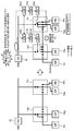
- the smart switches 10a and 10b are switch mechanisms for connecting or releasing a power supply source as a load and a resource such as a power device, and an arbitrary number of loads and power supply sources are connected thereto. As shown in FIG. 1, loads 50a to 50d are connected to smart switch 10a, and power line 40, generator 60 and storage battery 62a are connected as power supply sources. In addition, a load 50a is connected to the smart switch 10b, and a power line 40 and a storage battery 62b are connected as power supply sources.
- the smart switches 10a and 10b can not only turn on and off the supply of power to the load, but also select a specific power supply source from a plurality of power supply sources and connect it to an arbitrary load.
- the smart switch 10a includes physical switches PS1 to PS3b, closes the physical switches PS1 and PS3b and opens the physical switches PS2 and PS3a, and loads the power of the generator 60 with loads 50c and 50d.
- the power of the storage battery 62a is supplied to the load 50b.
- the smart switch 10b supplies the power of the storage battery 62b to the load 50a by closing the physical switch PS4.
- the smart switches 10a and 10b include a local communication policy (Local Service: LCP) provided from the grid manager 20 and a local service policy (Local Service provided from the service manager) in a storage unit (not shown) such as a memory.
- the local communication policy is definition information that defines communication conditions such as a communication path, communication parameters, and destination information used by the smart switch for communication with the outside for each assumed situation.
- the local service policy is definition information that defines a load and a resource to be supplied to the load (power amount or the like) for each assumed situation.
- the smart switch 10a, 10b realizes switching of the power supply source that is not allowed to delay by its own judgment based on the local policy, but realizes switching of the power supply source based on an instruction of the grid manager 20 described later. May be.
- Local communication policy and local service policy enable cooperation between multiple smart switches.
- the smart switch 10a supplies the power of the storage battery 62b to the load 50a by opening the physical switch PS2 and closing the physical switch PS4 in cooperation with the smart switch 10b.
- the local communication policy and the local service policy enable an autonomous operation in units of the own smart switch. That is, the smart switch controls the physical switch based on each policy if continuous power supply is possible only by controlling the physical switch under its control.
- the smart switch 10a selects either the power from the power line 40 or the power from the generator 60 by controlling the physical switches PS3a and PS3b based on the local service policy, and the load 50c. In addition, power can be supplied to the load 50d.
- Smart switches 10a and 10b also have a function of detecting power supply sources and load problems.
- the smart switch 10a, 10b detects a malfunction of a subordinate load, it can control the power supply to the subordinate load by autonomously controlling the physical switch based on the local service policy.
- the smart switch may connect a plurality of power supply sources and a plurality of loads like the smart switch 10a shown in FIG. 1, or connect a single power supply source and a single load like the smart switch 10b. It doesn't matter.
- the scale and arrangement of the smart switch can be set according to the arrangement state of the load in the plant or the like, the position of the power receiving facility that receives power supply, and the like.
- the grid manager 20 is a management device that manages a plurality of smart switches 10a and 10b and generates a local communication policy held by each smart switch.
- the grid manager 20 is connected to the plurality of smart switches 10a and 10b via the network 42, and realizes cooperative operation of the plurality of smart switches 10a and 10b. Further, the grid manager 20 generates a local communication policy for each smart switch 10a, 10b and provides it to each smart switch.
- Grid manager 20 has a global communication policy (Global GCP).
- the global communication policy assumes communication paths, communication parameters, destination information, etc. for communication with subordinate smart switches 10a and 10b, communication between smart switches 10a and 10b, and communication with the upper level service manager 30. Definition information defined for each status.
- the global communication policy is generated and held by the grid manager 20 in response to an instruction from the service manager 30 or the like.
- the grid manager 20 also has a function of detecting a power supply source or load failure, similar to the smart switches 10a and 10b.
- the grid manager 20 detects a failure of the power supply source, it can instruct the smart switches 10a and 10b under its control to change the power supply route based on the grid communication policy.
- the service manager 30 is a management device that manages the grid manager 20 to set the service contents of the entire system and generates local service policies held by each smart switch.
- the service manager 30 generates a local service policy for each smart switch and provides it to each smart switch.
- the service manager 30 has a global service policy (Global Service Policy: Global GSP).
- the global service policy is definition information that defines power supply standards for the entire plant managed by the resource management system 1.
- the global service policy includes information on the load, information on the power required for the load, and information on the arrangement of the load and the power supply source.
- the cloud 35 is an information providing system including, for example, a server and a database that provide weather information.
- the cloud 35 provides the service manager 30 with, for example, lightning strike prediction information that causes a momentary drop.
- the smart switches 10a and 10b of the embodiment include a physical switch PSn, a resource measurement controller 100, a resource route manager 110, and a resource route controller 120.
- the resource measurement controller 100 determines the power supply route, for example, load information of loads 50a to 50d, power generation information including the power generation amount of the generator 60, and power storage information of the storage batteries 62a and 62b. Are collected and provided to the resource route manager 110.
- the resource measurement controller 100 monitors the failure of the load and the power supply source through collection of such information groups, and notifies the resource route manager 110 of the occurrence of the failure of the load and the power supply source.
- the resource route manager 110 determines service quality (what kind of power supply is performed) in the smart switches 10a and 10b according to the route determination information and the local service policy provided from the service manager 30. .
- RRM Resource Route Manager
- the resource route controller 120 determines a supply route of power as a resource based on the determination of the resource route manager 110. That is, the resource route controller 100, the resource route manager 110, and the resource measurement controller 120 cooperate with each other to determine a resource supply route.
- the power supply route is changed by the resource route controller 120 performing opening / closing control of the physical switches PSn under the smart switches 10a and 10b with a control signal.
- the smart switches 10a and 10b of the embodiment include a terminal measurement controller 130, a terminal communication manager 140, and a terminal communication controller 150.
- the terminal measurement controller 130 (Terminal Measurement Controller: TMC) collects communication control information necessary for communication control and provides it to the terminal communication manager 140.
- a terminal communication manager 140 (Terminal Communication Manager: TCM) controls communication between the smart switch and the outside based on the local communication policy provided from the grid manager 20. Note that when the resource route manager 110 determines the power supply linked with another smart switch, the terminal communication manager 140 sets a communication path with the linked smart switch based on the local communication policy.
- the terminal communication controller 150 (Terminal Communication Controller: TCC) performs communication by controlling the communication devices of the smart switches 10a and 10b based on instructions from the terminal communication manager 140.
- the grid manager 20 of the embodiment includes a grid measurement controller 200, a grid communication manager 210, a grid communication controller 220, and a local communication policy controller 230.
- the grid measurement controller 200 acquires communication control information necessary for communication control with the subordinate smart switch and communication control with the service manager 30, and provides the communication control information to the grid communication manager 210.
- the grid measurement controller 200 also has a function of detecting a failure contained in a subordinate smart switch and a related power supply source.
- the Grid Communication Manager 210 communicates between the smart switches 10a and 10b, communicates with the smart switches 10a and 10b, communicates with the service manager 30, and further loads and power supply under the control. Monitor for defects.
- the grid communication manager 210 cooperates with the service manager 30 to determine a local communication policy including communication means and frequency.
- the grid communication controller 220 Grid Communication Controller: ⁇ GCC
- the local communication policy controller 230 (Local Communication Policy Controller: LCC) provides the local communication policy to the smart switches 10a and 10b and instructs rewriting thereof.
- the service manager 30 of the embodiment includes a service quality measurement controller 300, a cloud service manager 310, a communication controller 320, and a local service policy controller 330.
- the service quality measurement controller 300 measures the state of service quality provided by the resource management system 1 of the embodiment and provides it to the cloud service manager 310.
- the cloud service manager 310 Cloud Service Manager: CSM
- CSM Cloud Service Manager
- the service policy is changed, or the grid manager 20 is instructed to change the communication policy.
- the communication controller 320 (Communication Controller: CC) sets the communication method according to the instruction of the grid manager 20 and communicates.
- the local service policy controller 330 (Local Service Policy Controller: LSC) instructs the change when the local service policy of each smart switch 10a, 10b becomes necessary due to changes or fluctuations in the loads 50a to 50d. To do.
- the cloud 35 includes a server 350 and a database 360 that store information on fields related to changes in the local communication policy and the local service policy, such as weather forecast information and production management information. Is included.
- a plurality of smart switches are arranged for management targets including a plurality of loads, and grid managers for managing the smart switches are arranged hierarchically.
- flexible resource supply control can be performed according to the length of the allowable delay related to the resource supply stop time. That is, for a response to an instantaneous drop without time delay, the smart switch autonomously changes the supply route based on the local service policy.
- the smart switch and the grid manager cooperate to change the supply route over a range extending over a plurality of smart switches. This enables dynamic supply control according to the load.
- the resource management system of this embodiment includes a service manager that manages services separately from the grid manager that manages smart switches, the service quality of the entire providing system can be ensured.
- the resource management system of this embodiment can change the local service policy and the local communication policy, which are the criteria for the smart switch to perform resource supply control. It can be applied to other businesses. This means that a person who owns the resource management system of the embodiment can provide a resource management service as a cloud service to a user who is difficult to perform the resource management system by himself.
- events such as leveling of power supply for each equipment in the plant and adjustment of demand for power supply are problems that occur in daily work, and since preparations can be made in advance, delays of several minutes to several tens of minutes are also possible. May be acceptable.
- An event that predicts the timing of a lightning disaster and changes the power supply route in advance is performed under careful planning, so that a delay of several hours may be allowed.
- the difference in allowable delay time is related to the range affected by the load and power supply malfunction. For example, when an instantaneous drop occurs in a plant, an autonomous recovery in units of smart switches is a principle because an allowable delay time is short. On the other hand, in the case of plant equipment failure, although the delay time allowed is longer than the occurrence of a sag, the influence of the failure is wide-ranging, so the cooperative recovery of the grid manager and smart switch is indispensable.
- Various states of power supply such as the occurrence of a sag and failure of equipment, are classified based on the delay time (time allowed for opening and closing the switch) that is allowed until the power supply stops and recovers. Is stored in a storage unit of the smart switch or the grid manager as a local service policy.
- the supply route change is shown as the state of power supply after predicting the instantaneous drop, such as the occurrence of an instantaneous drop in the plant, equipment failure, demand response with sufficient time, and lightning. Yes.
- autonomous control of smart switch alone coordinated control between smart switches, local control coordinated between grid manager and smart switch, and global control coordinated between grid managers, etc. Is defined as a countermeasure.
- the resource management system of the embodiment includes a smart switch that directly controls power supply to a load, a grid manager that comprehensively manages a plurality of smart switches, and a service policy table as shown in FIG. In addition to autonomous recovery of supply routes, it enables recovery linked with other smart switches.
- the resource route managers 110a and 110b include resource route determination units 111a and 111b, local service quality managers 112a and 112b, and information processing units 113a and 113b.
- the terminal communication managers 140a and 140b include terminal communication determination units 141a and 141b, local communication managers 142a and 142b, network access units 143a and 143b, and terminal measurement managers 144a and 144b.
- the resource measurement controller 100a detects an instantaneous drop in the load 50c, the detection result is sent to the information processing unit 113a of the resource route manager 110a.
- the local service quality manager 112a of the resource route manager 110a notifies the grid manager 20 and the smart switch 10b of the occurrence of a sag through the local communication manager 142a of the terminal communication manager 140a.
- the resource route determination unit 111a determines the disconnection of the power supply source (for example, the power line 40) that is the cause of the instantaneous drop based on the local service policy, and notifies the resource route controller 120a.
- the resource route controller 120a opens the physical switch PS3a according to the notification, closes the physical switch PS3b, and switches the power supply to the load 50c from the power line 40 to the generator 60.
- the resource route determination unit 111a determines a power supply route in preparation for the occurrence of an instantaneous drop in cooperation with another smart switch 10b in accordance with an instruction from the local service quality manager 112a.
- the smart switch itself controls the physical switch that is detected by the smart switch and requires low delay, but the physical switch cooperates with other smart switches to perform physical control. Control of the switch may be realized. In this cooperative control, the smart switches may operate in cooperation with each other via a grid manager positioned at a higher level, or the smart switches may operate in direct cooperation.
- the resource route manager 110c includes a resource route determination unit 111c, a local service quality manager 112c, and an information processing unit 113c.
- the terminal communication manager 140c includes a terminal communication determination unit 141c, a local communication manager 142c, a network access unit 143c, and a terminal measurement manager 144c.
- the grid communication manager 210 includes a grid communication policy determination unit 211, a local communication policy determination unit 212, a network access unit 213, a grid communication manager 214, and an information processing unit 215.
- the grid measurement controller 200 detects an instantaneous drop at the load 50e, the detection result is sent to the information processing unit 215 of the grid communication manager 210.
- the network access unit 213 of the grid communication manager 210 sends the detected voltage sag information to the subordinate smart switch 10c.
- the local communication manager 142c of the smart switch 10c receives the instantaneous drop information from the grid manager 20.
- the received instantaneous drop information is sent to the local service quality manager 112c.
- the local service quality manager 112c notifies the smart switch 10d or 10e of the occurrence of a sag via the local communication manager 142c based on the received sag information and the local service policy.
- the resource route determination unit 111c determines the disconnection of the power supply source (for example, the power line 40) that is the cause of the instantaneous drop, and notifies the resource route controller 120c.
- the resource route controller 120c opens the physical switch PS3a according to the notification, closes the physical switch PS3b, and switches the power supply from the power line 40 to the generator 60c.
- the resource route determination unit 111c determines a power supply route in preparation for the occurrence of a sag by cooperating with other smart switches 10d and 10e in accordance with an instruction from the local service quality manager 112c.
- FIG. 6 shows the operation outline of Operation Example 2.
- the local communication manager 142c of the smart switch 10c and the local communication manager 142e of the smart switch 10e Exchange low information (same (b)).
- the local service quality manager 112c and the local service quality manager 112e control each physical switch in cooperation with each other, and supply the power of the generator 60c not only to the load 50e but also to the load 50g and the load 50h (the same ( c)). That is, a plurality of smart switches cooperate to change the power supply route.
- the delay time T2-T1 is set to T1 when the time at which a malfunction such as an instantaneous drop is detected is T1, and the time when the power supply route is scheduled to be changed is T2.
- a power supply route that is equal to or shorter than the allowable delay time for each event shown in FIG. 3 is selected. The same applies to the communication path from the grid manager 20 to the smart switch 10c, and the grid communication controller 220 selects a communication path in which the communication from the grid manager 20 to the smart switch 10c is sufficiently less than the allowable delay time.
- the smart switches cooperate to control the physical switch for the abnormality detected by the grid manager, but this cooperative operation is realized via the grid manager.
- the smart switch itself may directly cooperate with another smart switch to realize the control.
- the resource measurement controller 100c detects a failure (abnormality) in the subordinate load ((a) in FIG. 8)
- the detection result is sent to the local service quality manager 112c through the information processing unit 113c of the resource route manager 110c.
- the local service quality manager 112c notifies the grid manager 20 of the occurrence of equipment failure via the local communication manager 142c of the terminal communication manager 140c based on the local service policy.
- the grid communication manager 210 of the grid manager 20 Upon receiving the notification of the device failure occurrence, the grid communication manager 210 of the grid manager 20 reconstructs the power supply routing. Specifically, the grid communication manager 210 can communicate with the appropriate communication means according to the abnormal level of the equipment failure (for example, the communication means capable of transmitting information in the shortest time according to the available channels and the degree of congestion of the communication method). ) Is selected. Then, the power routing is reconfigured so that the subordinate smart switches 10c to 10e can realize the power supply flow for avoiding the problem.
- the abnormal level of the equipment failure for example, the communication means capable of transmitting information in the shortest time according to the available channels and the degree of congestion of the communication method.
- the grid communication manager 210 selects a smart switch that can recalculate the power route at the fastest speed and instructs to reconstruct the power supply route ((b) in FIG. 8 ( c)). In the example illustrated in FIG. 8, the grid communication manager 210 instructs the smart switch 10e having a low CPU usage rate among subordinate smart switches to recalculate the power route.
- the smart switch 10e Upon receiving the instruction, the smart switch 10e performs an operation for reconstructing the power supply route using the latest information held by the local communication manager 142e and the local service quality manager 112e.
- the reconfigured smart switch instructs the smart switch that needs to change the power supply route to change the route ((d)).
- the local communication manager 10d of the smart switch Upon receiving the instruction, the local communication manager 10d of the smart switch passes information related to the route change to the local service quality manager 112d.
- the local quality of service manager 112d reconstructs the power supply route based on the received information.
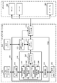
- the cloud service manager 310 includes a communication network determination unit 311, a local service policy determination unit 312, a network access unit 313, a communication manager 314, a global service quality manager 316, and an information processing unit 315.
- the grid manager 20 When there is a power saving request to one of the plurality of grid managers 20, the grid manager 20 that has received the power saving request sends an adjustment request to the service manager 30 to which it belongs.
- the global service quality manager 316 of the service manager 30 that has received the adjustment request causes the local service policy determination unit 312 to create an optimal local service policy based on the status of the subordinate grid manager 20.
- the global service quality manager 316 sends the created local service policy to the grid manager 20 via the communication manager 314.
- the grid communication manager of the grid manager 20 When receiving the local service policy from the service manager 30, the grid communication manager of the grid manager 20 causes the local communication policy determination unit 212 to create a local communication policy suitable for the received local service policy.
- the global communication manager 214 sends the created local communication policy and the local service policy received from the service manager 30 to the subordinate smart switch.
- the local quality of service manager 112c Upon receiving the local communication policy and the local service policy from the global communication manager 214 of the grid manager 20, the local quality of service manager 112c applies the received local service policy, and the local communication manager 142c applies the received local communication policy. .
- the resource route determining unit 111c switches the power supply route as necessary.
- the global service quality manager 316 includes a service quality evaluation unit 341, a product process monitoring unit 342, a risk / impact evaluation unit 343, an economic loss evaluation unit 344, and a data access controller 345.
- the global service quality manager 316 of the service manager 30 refers to the production process and line status information in the plant to be managed, and evaluates the impact caused by the failure of power supply. In the evaluation, the global service quality manager 316 acquires weather information and lightning prediction information provided by the weather related office from the server 350 and the database 360 of the cloud 35.
- the local service policy determination unit 312 As a result of the impact evaluation, if it is determined that the power flow needs to be changed, the local service policy determination unit 312 generates a new local service policy.
- the communication manager 314 sends the generated local service policy to the grid manager 20.
- the global communication manager 214 of the grid manager 20 sends a new local service policy to the local service quality manager 112c of the smart switch 10c, and the local service quality manager 112c applies the received new local service policy.
- the local communication policy determination unit 212 of the grid manager 20 generates a local communication policy for satisfying the new local service policy.
- the global communication manager 214 sends the generated new local communication policy to the local communication manager 142c of the smart switch 10c.
- the local communication manager 142c applies the new local communication policy.
- the resource route determination unit 111c reconstructs the power supply route based on the new local service policy as necessary.
- a plurality of smart switches are arranged for a management target including a plurality of loads, grid managers that manage the smart switches are arranged in a hierarchy, and an upper grid Both the manager and the lower-level smart switch monitor power supply failures.
- the upper grid manager and service manager can change the local service policy and the local communication policy that are the operation reference in the smart switch that actually changes the power supply route, Even when the power supply management target covers a wide range, the supply path can be flexibly changed.
- the resource management system of the embodiment since the higher-level grid manager and service manager manage such a group of policies, it is not necessary for the operator of the factory to be managed to manage the policy. This makes it possible to entrust resource management to a third party, and even if it is difficult to provide a self-operated communication network and management system, such as small and medium-sized companies and factories, the resource management system can be used. It can be easily introduced.
- the communication conditions are defined by the local communication policy and the global communication policy for communication among the smart switch, the grid manager, and the service manager, so that the communication path can be freely set. That is, not only a self-operated communication network but also a telecommunication network provided by a third party can be used. Also, by defining a plurality of communication paths, it is possible to freely select a communication path that speeds up switch control.
- the resource management system of the embodiment manages power supply, but is not limited to this.
- the present invention can be similarly applied to a target for stable supply using a plurality of resource supply sources for a plurality of loads and demand areas such as a gas supply and a water supply.
- power line 42 ... network, 44 ... Internet, 46 ... mobile network, 50a-50h ... load, 60 ... generator, 62a, 62b ... storage battery LSP ... local service policy, LCP ... local communication policy, PS1-PS4 ... physical switch.
Landscapes
- Engineering & Computer Science (AREA)
- Power Engineering (AREA)
- Business, Economics & Management (AREA)
- Emergency Management (AREA)
- Remote Monitoring And Control Of Power-Distribution Networks (AREA)
- Supply And Distribution Of Alternating Current (AREA)
- Power Sources (AREA)
- Theoretical Computer Science (AREA)
- Physics & Mathematics (AREA)
- General Engineering & Computer Science (AREA)
- General Physics & Mathematics (AREA)
Abstract
リソース管理システムは、第1 リソース供給源から供給されるリソースの状態を監視する第1 監視部と、第1 リソース供給源から供給されるリソースの状態に応じた第1 開閉信号を定義する第1 ポリシーを記憶した第1 記憶部と、第1 監視部の監視結果および第1 ポリシーに基づき第1 開閉信号を生成する第1 経路制御部と、第2 リソース供給源から供給されるリソースの状態を監 視する第2 監視部と、第2 リソース供給源から供給されるリソースの状態に応じた第2 開閉信号を定義する第2 ポリシーを記憶した第2 記憶部と、第2監視部の監視結果および第2 ポリシーに基づき第2 開閉信号を生成する第2経路制御部と、第1 リソース供給源から供給されるリソースの状態を監視する第3 監視部と、第3 監視部の監視結果に基づき第1 経路制御部および第2経路制御部の少なくとも一方を制御して第1 および第2 開閉信号の少なくとも一方を生成させる第3 経路制御部と、を具備する。
Description
本発明の実施形態は、リソース管理システムに関する。
生産工場などでは、Just-in-Time方式やFactory Automationシステム導入による無人化・自動化を行っている場合がある。こうした方式やシステムを導入した場合、それぞれのプロセスにおける機器の不具合や停止を防ぐことが重要である。
機器の不具合発生の原因の一つとして、落雷や突風など日常的な自然現象に起因する災害によって発生する電力の不安定性(いわゆる「瞬時電圧低下(瞬低)」)が挙げられる。電力の不安定性については、電源供給路の二重化やバックアップ電源などにより回避することが試みられている。
しかし、中小規模の工場の場合、コストやスペースの関係上、平均的な業務に合わせてプロセスを解析した上で重要度に応じて無停電電源装置(Uninterruptible Power Supply: UPS)を設置することが行われている。また、気象庁の雷予測等に基づき、手動で電源供給のオンオフを行う場合もある。
T.Takuno, Y.Kitamori, R.Takahashi, T.Hikihara, "Ac Power Routing System in Home Based on Demand and Supply Utilizing Distributed Power Source", Energies 2011, 4(5), 717-726
従来の電力供給(リソース供給)を管理するシステムでは、コストや設置スペースの問題もあり管理対象内の全ての機器を網羅することが難しく、また日々の生産工程や負荷の動的変化に対応することが難しいという問題がある。本発明はかかる問題を解決するためになされたもので、負荷や障害の動的変化に対応するとともに、低コストで多くの機器を管理することのできるリソース管理システムを提供することを目的としている。
実施形態に係るリソース管理システムは、(1)第1のリソース供給源と第1の負荷との接続の開閉を制御する第1の開閉信号を送出する第1の開閉制御部と、前記第1のリソース供給源から供給されるリソースの状態を監視する第1の監視部と、前記第1のリソース供給源から供給されるリソースの状態に応じた前記第1の開閉信号を定義する第1のポリシーを記憶した第1の記憶部と、前記第1の監視部の監視結果および前記第1のポリシーに基づき前記第1の開閉信号を生成する第1の経路制御部とを備える第1の開閉制御機構と、(2)前記第1のリソース供給源とは異なる第2のリソース供給源と第2の負荷との接続の開閉を制御する第2の開閉信号を送出する第2の開閉制御部と、前記第2のリソース供給源から供給されるリソースの状態を監視する第2の監視部と、前記第2のリソース供給源から供給されるリソースの状態に応じた前記第2の開閉信号を定義する第2のポリシーを記憶した第2の記憶部と、前記第2の監視部の監視結果および前記第2のポリシーに基づき前記第2の開閉信号を生成する第2の経路制御部とを備える第2の開閉制御機構と、(3)前記第1のリソース供給源から供給されるリソースの状態を監視する第3の監視部と、前記第3の監視部の監視結果に基づき前記第1の経路制御部および前記第2の経路制御部の少なくとも一方を制御して前記第1および第2の開閉信号の少なくとも一方を生成させる第3の経路制御部とを備えるグリッドマネージャと、を備えている。
本発明によれば、負荷や障害の動的変化に対応するとともに、低コストで多くの機器を管理することのできるリソース管理システムを提供することができる。
実施形態のリソース管理システムは、複数の負荷をもつプラントなどにおいて当該負荷にリソースを適切に供給するとともに、リソース供給の障害発生やその予測に応じてリソースの供給ルートの再構築を行う。リソースの供給ルートの制御は、障害の内容に応じて階層的に行われ、リソースの供給ルートを柔軟に再構築することができる。以下の説明においては、負荷として電力機器を複数もつプラントにおいて、リソースとして電力の供給を管理する例について説明する。
(実施形態の構成)
図1に示すように、実施形態のリソース管理システム1は、スマートスイッチ10a,10bと、グリッドマネージャ20と、サービスマネージャ30とを有している。スマートスイッチ10a,10bは、電力線40を介して電力の供給(リソースの供給)を受けるとともに、ネットワーク42を介してグリッドマネージャ20や他のスマートスイッチと相互に通信可能に接続されている。グリッドマネージャ20は、複数の通信経路(図1に示す例ではインターネット44およびモバイル網46)を介してサービスマネージャ30と接続されている。なお、実施形態のリソース管理システム1は、さらにインターネット44およびモバイル網46を介してサーバなどからなるクラウド35と接続されてもよい。
図1に示すように、実施形態のリソース管理システム1は、スマートスイッチ10a,10bと、グリッドマネージャ20と、サービスマネージャ30とを有している。スマートスイッチ10a,10bは、電力線40を介して電力の供給(リソースの供給)を受けるとともに、ネットワーク42を介してグリッドマネージャ20や他のスマートスイッチと相互に通信可能に接続されている。グリッドマネージャ20は、複数の通信経路(図1に示す例ではインターネット44およびモバイル網46)を介してサービスマネージャ30と接続されている。なお、実施形態のリソース管理システム1は、さらにインターネット44およびモバイル網46を介してサーバなどからなるクラウド35と接続されてもよい。
スマートスイッチ10a,10bは、電力機器などの負荷およびリソースとしての電力供給源を接続または開放するスイッチ機構であり、任意の数の負荷および電力供給源が接続されている。図1に示すように、スマートスイッチ10aには、負荷50a~50dが接続されるとともに、電力供給源として電力線40、発電機60および蓄電池62aが接続されている。また、スマートスイッチ10bには、負荷50aが接続されるとともに、電力供給源として電力線40および蓄電池62bが接続されている。
スマートスイッチ10a,10bは、負荷への電力の供給をオンオフするだけではなく、複数の電力供給源から特定の電力供給源を選択し、任意の負荷に接続することができる。図1に示す例では、スマートスイッチ10aは、物理スイッチPS1~PS3bを備えており、物理スイッチPS1およびPS3bを閉じるとともに物理スイッチPS2およびPS3aを開放状態として、発電機60の電力を負荷50cおよび50dに供給するとともに、蓄電池62aの電力を負荷50bに供給している。同様に、スマートスイッチ10bは、物理スイッチPS4を閉じることで、蓄電池62bの電力を負荷50aに供給している。
スマートスイッチ10a,10bは、メモリなどの記憶部(図示せず)に、グリッドマネージャ20から提供されるローカル通信ポリシー(Local Communication Policy: LCP)と、サービスマネージャから提供されるローカルサービスポリシー(Local Service Policy: LSP)とを有している。ローカル通信ポリシーは、スマートスイッチが外部との通信に用いる通信経路や通信パラメータ、相手先情報などの通信条件を、想定される状況ごとに定義した定義情報である。ローカルサービスポリシーは、負荷および当該負荷に供給すべきリソース(電力量等)を、想定される状況ごとに定義した定義情報である。スマートスイッチ10a,10bは、遅延の許されない電力供給源の切替については、ローカルポリシーに基づいて自己の判断で実現するが、後述するグリッドマネージャ20の指示に基づいて電力供給源の切替を実現してもよい。
ローカル通信ポリシーおよびローカルサービスポリシーは、複数のスマートスイッチ間の連携動作を可能にする。図1に示す例では、スマートスイッチ10aは、スマートスイッチ10bと連携して、それぞれが物理スイッチPS2を開放するとともに物理スイッチPS4を閉じることで、蓄電池62bの電力を負荷50aに供給している。また、ローカル通信ポリシーおよびローカルサービスポリシーは、自己のスマートスイッチ単位での自律的動作をも可能とする。すなわち、スマートスイッチは、自己の配下の物理スイッチの制御だけで継続的な電力供給が可能であれば、各ポリシーに基づいて物理スイッチを制御する。図1に示す例では、スマートスイッチ10aは、ローカルサービスポリシーに基づいて物理スイッチPS3aおよびPS3bを制御することで、電力線40からの電力または発電機60からの電力のいずれかを選択し、負荷50cおよび負荷50dに対して電力を供給することができる。
スマートスイッチ10a,10bは、電力供給源や負荷の不具合を検知する機能をも有している。スマートスイッチ10a,10bは、配下の負荷の不具合を検知した場合、ローカルサービスポリシーに基づいて自律的に物理スイッチを制御して配下の負荷への電力供給を制御することができる。
スマートスイッチは、図1に示すスマートスイッチ10aのように複数の電力供給源および複数の負荷を接続してもよいし、スマートスイッチ10bのように単独の電力供給源および単独の負荷を接続しても構わない。スマートスイッチの規模および配置は、プラントなどにおける負荷の配置状況や、電力供給を受ける受電設備の位置などに応じて設定することができる。
グリッドマネージャ20は、複数のスマートスイッチ10a,10bを管理するとともに、各々のスマートスイッチが保持するローカル通信ポリシーを生成する管理装置である。グリッドマネージャ20は、複数のスマートスイッチ10a,10bとネットワーク42を介して接続され、複数のスマートスイッチ10a,10bの連携動作を実現する。また、グリッドマネージャ20は、スマートスイッチ10a,10bごとのローカル通信ポリシーを生成して各スマートスイッチに提供する。
グリッドマネージャ20は、グローバル通信ポリシー(Global Communication Policy: GCP)を有している。グローバル通信ポリシーは、配下のスマートスイッチ10a,10bとの通信やスマートスイッチ10aおよび10b間の通信、さらには上位のサービスマネージャ30との通信について、通信経路や通信パラメータ、相手先情報などを、想定される状況ごとに定義した定義情報である。グローバル通信ポリシーは、サービスマネージャ30からの指示等に応じてグリッドマネージャ20が自ら生成し保持する。
グリッドマネージャ20は、スマートスイッチ10a,10bと同様、電力供給源や負荷の不具合を検知する機能をも有している。グリッドマネージャ20が電力供給源の不具合を検知した場合、グリッド通信ポリシーに基づいて配下のスマートスイッチ10a,10bに電力供給ルートの変更を指示することができる。
サービスマネージャ30は、グリッドマネージャ20を管理してシステム全体のサービス内容を設定するとともに、各々のスマートスイッチが保持するローカルサービスポリシーを生成する管理装置である。サービスマネージャ30は、スマートスイッチごとのローカルサービスポリシーを生成して各スマートスイッチに提供する。
サービスマネージャ30は、グローバルサービスポリシー(Global Service Policy: GSP)を有している。グローバルサービスポリシーは、リソース管理システム1が管理するプラント全体に対する電力供給の基準を定義した定義情報である。グローバルサービスポリシーには、負荷の情報や当該負荷に必要な電力の情報、負荷や電力供給源の配置などの情報が含まれる。
クラウド35は、例えば気象情報を提供するサーバやデータベースなどを含む情報提供システムである。クラウド35は、例えば瞬低の原因となる落雷予測情報などをサービスマネージャ30に提供する。
続いて、図2を参照して、実施形態に係るリソース管理システム1の機能構成を詳細に説明する。
図2に示すように、実施形態のスマートスイッチ10a,10bは、物理スイッチPSn、リソース測定コントローラ100、リソースルートマネージャ110、およびリソースルートコントローラ120を備えている。
リソース測定コントローラ100(Resource Measurement Controller: RMC)は、電力供給ルートを決定するため、例えば、負荷50a~50dの負荷情報、発電機60の発電量などを含む発電情報、蓄電池62a,62bの蓄電情報などのルート決定情報を収集し、リソースルートマネージャ110に提供する。リソース測定コントローラ100は、かかる情報群の収集を通じて負荷や電力供給源の不具合を監視し、負荷や電力供給源の不具合発生をリソースルートマネージャ110に通知する。
リソースルートマネージャ110(Resource Route Manager: RRM)は、スマートスイッチ10a,10bにおけるサービス品質(どのような電力供給を行うか)を、ルート決定情報およびサービスマネージャ30から提供されたローカルサービスポリシーに従って決定する。また、リソース測定コントローラ100が負荷や電力供給の不具合発生を検知した場合、リソースルートマネージャ110は、不具合の状況に応じて電力供給ルートの再構築の決定を行う。
リソースルートコントローラ120(Resource Route Controller: RRC)は、リソースルートマネージャ110の決定に基づきリソースたる電力の供給ルートを決定する。すなわち、リソースルートコントローラ100、リソースルートマネージャ110およびリソース測定コントローラ120は、互いに協働してリソースの供給ルートを決定する。電力の供給ルートの変更は、リソースルートコントローラ120がスマートスイッチ10a,10b配下の物理スイッチPSnそれぞれを制御信号により開閉制御することにより行う。
また、実施形態のスマートスイッチ10a,10bは、ターミナル測定コントローラ130、ターミナル通信マネージャ140、およびターミナル通信コントローラ150を備えている。
ターミナル測定コントローラ130(Terminal Measurement Controller: TMC)は、通信制御に必要な通信制御情報を収集し、ターミナル通信マネージャ140に提供する。ターミナル通信マネージャ140(Terminal Communication Manager: TCM)は、グリッドマネージャ20から提供されたローカル通信ポリシーに基づき、スマートスイッチと外部との通信を制御する。なお、ターミナル通信マネージャ140は、リソースルートマネージャ110が他のスマートスイッチと連携した電力供給を決定した場合、ローカル通信ポリシーに基づいて連携するスマートスイッチとの通信路を設定する。ターミナル通信コントローラ150(Terminal Communication Controller: TCC)は、ターミナル通信マネージャ140の指示に基づき、スマートスイッチ10a,10bの通信デバイスを制御して通信を行う。
また、図2に示すように、実施形態のグリッドマネージャ20は、グリッド測定コントローラ200、グリッド通信マネージャ210、グリッド通信コントローラ220、およびローカル通信ポリシーコントローラ230を備えている。
グリッド測定コントローラ200(Grid Measurement Controller: GMC)は、配下のスマートスイッチとの通信制御やサービスマネージャ30との通信制御に必要な通信制御情報を取得し、グリッド通信マネージャ210に提供する。併せて、グリッド測定コントローラ200は、リソースルートマネージャ110と同様、配下のスマートスイッチに収容された負荷や関係する電力供給源の不具合を検知する機能をも有している。
グリッド通信マネージャ210(Grid Communication Manager: GCM)は、スマートスイッチ10a,10b間の通信状態、スマートスイッチ10a,10bとの通信状態、およびサービスマネージャ30との通信状態、さらには配下の負荷や電力供給の不具合の有無を監視する。併せて、グリッド通信マネージャ210は、サービスマネージャ30と連携して、通信手段や頻度などを含むローカル通信ポリシーを決定する。グリッド通信コントローラ220(Grid Communication Controller: GCC)は、スマートスイッチ10a,10bおよびサービスマネージャ30との通信に係る通信方式・通信頻度などを制御する。ローカル通信ポリシーコントローラ230(Local Communication Policy Controller: LCC)は、スマートスイッチ10a,10bにローカル通信ポリシーを提供してその書き換えを指示する。
図2に示すように、実施形態のサービスマネージャ30は、サービス品質測定コントローラ300、クラウドサービスマネージャ310、通信コントローラ320、およびローカルサービスポリシーコントローラ330を備えている。
サービス品質測定コントローラ300(Service Quality Measurement Controller: SQC)は、実施形態のリソース管理システム1が提供するサービス品質の状態を測定し、クラウドサービスマネージャ310に提供する。クラウドサービスマネージャ310(Cloud Service Manager: CSM)は、実施形態のリソース管理システム1のユーザが定めたサービスレベルを維持しているかサービス全体を監視する。そして、スマートスイッチ10a,10bに接続された負荷50a~50dの変更や変動等により、瞬低や瞬電などリソースの供給停止時間に関する許容遅延が変化した場合に、各スマートスイッチ10a,10bのローカルサービスポリシーを変更したり、グリッドマネージャ20に通信ポリシーの変更を指示したりする。
通信コントローラ320(Communication Controller: CC)は、グリッドマネージャ20の指示に応じた通信方式を設定して通信する。ローカルサービスポリシーコントローラ330(Local Service Policy Controller: LSC)は、負荷50a~50dの変更や変動等により、各スマートスイッチ10a,10bのローカルサービスポリシーの変更が必要になった場合に、当該変更を指示する。
さらに、図2に示すように、実施形態のクラウド35は、ローカル通信ポリシーやローカルサービスポリシーの変更に関係する分野の情報、例えば気象予測情報や生産管理情報などが格納されたサーバ350やデータベース360を含んでいる。
このように、実施形態のリソース管理システムは、複数の負荷を含む管理対象に対して複数のスマートスイッチを配設し、当該スマートスイッチを管理するグリッドマネージャを階層的に配設している。かかる構成により、リソースの供給停止時間に関する許容遅延の長さに応じて柔軟なリソース供給制御が可能となる。すなわち、時間的に猶予のない瞬低に対する対応については、スマートスイッチがローカルサービスポリシーに基づいて自律的に供給ルートを変更する。また、比較的時間にゆとりのある瞬低予測に対する対応については、スマートスイッチおよびグリッドマネージャが協働し、複数のスマートスイッチにまたがる範囲にわたって供給ルートを変更する。これにより、負荷に応じた動的な供給制御が可能になる。
また、この実施形態のリソース管理システムは、スマートスイッチを管理するグリッドマネージャとは別に、サービスを管理するサービスマネージャを備えたので、提供システム全体のサービス品質を担保することができる。
さらに、この実施形態のリソース管理システムは、スマートスイッチがリソース供給制御をおこなう基準とするローカルサービスポリシーやローカル通信ポリシーを変更可能としたので、管理対象たるユーザの負荷やその配置に関わらずあらゆる形態の事業に適用することができる。これは、リソース管理システムを自営で行うことが難しいユーザに対して、実施形態のリソース管理システムを保有する者がクラウドサービスとしてリソース管理サービスを提供可能になることを意味している。
(リソース供給停止から復旧までの許容遅延)
ここで、図3を参照して、負荷への電力供給の停止から復旧するまでに許容される遅延時間について説明する。
ここで、図3を参照して、負荷への電力供給の停止から復旧するまでに許容される遅延時間について説明する。
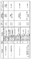
電力などのリソース供給が障害により停止してから復旧するまでには、一定の時間を要するのが一般的である。一方で、負荷たる電力機器には、いかなる遅延も許されないものから、状況によりある程度の遅延が許容されるものまで様々なものが存在する。例えば、図3に示すように、プラントでの瞬低発生は、製品の品質や信頼性に直結する事象であるから、1秒以下での復帰が望まれる。プラントでの機器故障は、他の機器への影響を防ぐことが重要であり、数秒から数分単位の遅延で復帰すればよい。さらに、プラント内の機器毎の電力供給の平準化や電力供給の需要調整などの事象では、日常の業務において発生する問題であり、予め準備が可能であるから数分から数十分程度の遅延も許容され得る。雷災害の時期を予測して予め電力供給ルートを変更するような事象では、綿密な計画のもとに行われるものであるから、数時間単位の遅延も許容され得る。
また、許容される遅延時間の相違は、負荷や電力供給の不具合の影響が及ぶ範囲とも関連する。例えば、プラントでの瞬低発生の場合は、許容される遅延時間が短いことからスマートスイッチ単位での自律的復旧が原則となる。一方、プラントの機器故障発生の場合は、瞬低発生よりも許容される遅延時間が長いものの、不具合の影響が広範囲に及ぶことから、グリッドマネージャおよびスマートスイッチの連携的復旧が不可欠となる。
瞬低発生や機器の故障など電力供給の各種状態は、電力供給が停止し復旧するまでに許容される遅延時間(スイッチの開閉に許容される時間)を基準として分類されており、それぞれの状態に適した電力供給ルートの変更方法(スイッチの開閉の組合せ方法)が対応付けられたテーブルが、ローカルサービスポリシーとしてスマートスイッチやグリッドマネージャの記憶部に格納されている。図3に示す例では、プラントでの瞬低発生や機器故障、時間的に余裕のあるデマンドレスポンス、さらには雷など瞬低を予測した上での供給ルート変更が電力供給の状態として示されている。そして、各々の状態(予測)に対応して、スマートスイッチ単独の自律制御、スマートスイッチどうしの連携制御、グリッドマネージャとスマートスイッチとが連携したローカル制御、さらにはグリッドマネージャどうしが連携したグローバル制御などが対応策として定義づけられている。実施形態のリソース管理システムは、負荷への電力供給を直接制御するスマートスイッチと、複数のスマートスイッチを包括して管理するグリッドマネージャと、図3に示すようなサービスポリシーテーブルを備えたので、電力供給ルートの自律的な復旧に加えて他のスマートスイッチと連携した復旧を可能にしている。
(実施形態の動作例1:スマートスイッチが不具合を検出)
以下、図4を参照して、実施形態のリソース管理システムの動作を説明する。図4に示すように、リソースルートマネージャ110a,110bは、リソースルート決定部111a,111b、ローカルサービス品質マネージャ112a,112bおよび情報処理部113a,113bを備えている。また、ターミナル通信マネージャ140a,140bは、ターミナル通信決定部141a,141b、ローカル通信マネージャ142a,142b、ネットワークアクセス部143a,143bおよびターミナル測定マネージャ144a,144bを備えている。
以下、図4を参照して、実施形態のリソース管理システムの動作を説明する。図4に示すように、リソースルートマネージャ110a,110bは、リソースルート決定部111a,111b、ローカルサービス品質マネージャ112a,112bおよび情報処理部113a,113bを備えている。また、ターミナル通信マネージャ140a,140bは、ターミナル通信決定部141a,141b、ローカル通信マネージャ142a,142b、ネットワークアクセス部143a,143bおよびターミナル測定マネージャ144a,144bを備えている。
リソース測定コントローラ100aが負荷50cにおける瞬低を検出すると、検出結果はリソースルートマネージャ110aの情報処理部113aに送られる。
リソースルートマネージャ110aのローカルサービス品質マネージャ112aは、ローカルサービスポリシーに基づき、ターミナル通信マネージャ140aのローカル通信マネージャ142aを介して、グリッドマネージャ20やスマートスイッチ10bに瞬低発生を通知する。
リソースルート決定部111aは、ローカルサービスポリシーに基づいて瞬低の発生原因である電力供給源(例えば電力線40)の切り離しを決定し、リソースルートコントローラ120aに通知する。
リソースルートコントローラ120aは、通知に従って物理スイッチPS3aを開放するとともに物理スイッチPS3bを閉じて、負荷50cへの電力供給を電力線40から発電機60へ切り替える。
リソースルート決定部111aは、ローカルサービス品質マネージャ112aからの指示に従い、他のスマートスイッチ10bと連携し、瞬低発生に備えた電力供給ルートを決定する。このように、実施形態のリソース管理システムによれば、スマートスイッチが検出し低遅延を要する物理スイッチの制御を、スマートスイッチ自身が単独で実現しているが、他のスマートスイッチと連携して物理スイッチの制御を実現してもよい。このときの連携制御は、上位に位置するグリッドマネージャを介してスマートスイッチどうしが連携動作してもよいし、スマートスイッチどうしが直接連携動作してもよい。
(実施形態の動作例2:グリッドマネージャが不具合を検出)
続いて、図5および6を参照して、実施形態のリソース管理システムの他の動作を説明する。図5に示すように、リソースルートマネージャ110cは、リソースルート決定部111c、ローカルサービス品質マネージャ112cおよび情報処理部113cを備えている。また、ターミナル通信マネージャ140cは、ターミナル通信決定部141c、ローカル通信マネージャ142c、ネットワークアクセス部143cおよびターミナル測定マネージャ144cを備えている。さらに、グリッド通信マネージャ210は、グリッド通信ポリシー決定部211、ローカル通信ポリシー決定部212、ネットワークアクセス部213、グリッド通信マネージャ214および情報処理部215を備えている。
続いて、図5および6を参照して、実施形態のリソース管理システムの他の動作を説明する。図5に示すように、リソースルートマネージャ110cは、リソースルート決定部111c、ローカルサービス品質マネージャ112cおよび情報処理部113cを備えている。また、ターミナル通信マネージャ140cは、ターミナル通信決定部141c、ローカル通信マネージャ142c、ネットワークアクセス部143cおよびターミナル測定マネージャ144cを備えている。さらに、グリッド通信マネージャ210は、グリッド通信ポリシー決定部211、ローカル通信ポリシー決定部212、ネットワークアクセス部213、グリッド通信マネージャ214および情報処理部215を備えている。
グリッド測定コントローラ200が負荷50eにおける瞬低を検出すると、検出結果はグリッド通信マネージャ210の情報処理部215に送られる。
グリッド通信マネージャ210のネットワークアクセス部213は、検出した瞬低情報を配下のスマートスイッチ10cに送る。スマートスイッチ10cのローカル通信マネージャ142cは、グリッドマネージャ20からの瞬低情報を受信する。受信した瞬低情報は、ローカルサービス品質マネージャ112cへ送られる。
ローカルサービス品質マネージャ112cは、受信した瞬低情報とローカルサービスポリシーに基づいて、ローカル通信マネージャ142cを介してスマートスイッチ10dや10eに瞬低発生を通知する。
リソースルート決定部111cは、瞬低の発生原因である電力供給源(例えば電力線40)の切り離しを決定し、リソースルートコントローラ120cに通知する。
リソースルートコントローラ120cは、通知に従って物理スイッチPS3aを開放するとともに物理スイッチPS3bを閉じて、負荷50eへの電力供給を電力線40から発電機60cへ切り替える。
リソースルート決定部111cは、ローカルサービス品質マネージャ112cからの指示に従い、他のスマートスイッチ10dや10eと連携し、瞬低発生に備えた電力供給ルートを決定する。
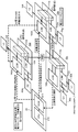
図6および7は、動作例2の動作概要を示している。図6に示すように、瞬低情報がグリッドマネージャ20からスマートスイッチ10cに送られると(図6中(a))、スマートスイッチ10cのローカル通信マネージャ142cおよびスマートスイッチ10eのローカル通信マネージャ142eは瞬低情報を交換する(同(b))。次いで、ローカルサービス品質マネージャ112cとローカルサービス品質マネージャ112eは互いに連携してそれぞれの物理スイッチを制御し、発電機60cの電力を負荷50eだけでなく負荷50gや負荷50hへ供給している(同(c))。すなわち、複数のスマートスイッチが連携して電力供給ルートを変更している。
また、図7に示すように、電力供給ルートの変更は、瞬低等の不具合を検知した時刻をT1、電力供給ルートの変更が完了する予定時刻をT2としたとき、遅延時間T2-T1が図3に示す事象ごとの許容遅延時間以下となる電力供給ルートが選択される。グリッドマネージャ20からスマートスイッチ10cまでの通信経路も同様であり、グリッド通信コントローラ220は、グリッドマネージャ20からスマートスイッチ10cへの通信が許容遅延時間を充分下回る時間となる通信経路を選択する。
このように、実施形態のリソース管理システムによれば、グリッドマネージャが検出した異常について、スマートスイッチどうしが連携して物理スイッチを制御しているが、この連携動作は、グリッドマネージャを介して実現してもよいし、スマートスイッチ自身が他のスマートスイッチと直接連携して制御を実現してもよい。
(実施形態の動作例3:特定のスマートスイッチが供給ルート構築)
続いて、図5および8を参照して、実施形態のリソース管理システムの他の動作を説明する。
続いて、図5および8を参照して、実施形態のリソース管理システムの他の動作を説明する。
リソース測定コントローラ100cが配下の負荷における故障(異常)を検出すると(図8中(a))、検出結果はリソースルートマネージャ110cの情報処理部113cを通じてローカルサービス品質マネージャ112cに送られる。
ローカルサービス品質マネージャ112cは、ローカルサービスポリシーに基づき、ターミナル通信マネージャ140cのローカル通信マネージャ142cを介して、グリッドマネージャ20に機器故障発生を通知する。
機器故障発生の通知を受けると、グリッドマネージャ20のグリッド通信マネージャ210は、電力の供給ルーティングの再構築を行う。具体的には、グリッド通信マネージャ210は、機器故障の異常レベルに応じて適切なコミュニケーション手段(例えば、利用可能なチャネルや通信方式の混雑度などに応じて、最短時間で情報伝達可能なコミュニケーション手段)を選択する。そして、配下のスマートスイッチ10c~10eに問題回避のための電力供給フローを実現できるよう電力ルーティングの再構築を行う。
このとき、グリッドマネージャ20のグリッド通信マネージャ210が保持している各スマートスイッチへの電力供給ルートに関する情報が、所定時間以上古い情報である場合(例えば30分前)、かつ、複数のスマートスイッチが連携して経路再構築を行う必要がある場合、グリッド通信マネージャ210は、最速に電力ルート再計算が行えるスマートスイッチを選択して電力供給ルートの再構築を指示する(図8中(b)(c))。図8に示す例では、グリッド通信マネージャ210は、配下のスマートスイッチのうちCPU使用率の低いスマートスイッチ10eに電力ルートの再計算を指示している。
指示を受けたスマートスイッチ10eは、自己のローカル通信マネージャ142eやローカルサービス品質マネージャ112eが保有する最新の情報を用いて電力供給ルートを再構築する演算を行う。
再構築処理が完了すると、再構築を行ったスマートスイッチが、電力供給ルートの変更が必要なスマートスイッチに対してルートの変更を指示する(同(d))。
指示を受けたスマートスイッチのローカル通信マネージャ10dは、ルート変更に係る情報をローカルサービス品質マネージャ112dに渡す。ローカルサービス品質マネージャ112dは、受け取った情報に基づき電力供給ルートを再構築する。
(実施形態の動作例4:ポリシーの変更)
続いて、図5および9を参照して、実施形態のリソース管理システムの他の動作を説明する。図9に示すように、クラウドサービスマネージャ310は、通信ネットワーク決定部311、ローカルサービスポリシー決定部312、ネットワークアクセス部313、通信マネージャ314、グローバルサービス品質マネージャ316および情報処理部315を備えている。
続いて、図5および9を参照して、実施形態のリソース管理システムの他の動作を説明する。図9に示すように、クラウドサービスマネージャ310は、通信ネットワーク決定部311、ローカルサービスポリシー決定部312、ネットワークアクセス部313、通信マネージャ314、グローバルサービス品質マネージャ316および情報処理部315を備えている。
複数のグリッドマネージャ20のうちの一つに対して節電要請があった場合、節電要請を受けたグリッドマネージャ20は、自己が属するサービスマネージャ30へ調整依頼を送る。
調整依頼を受けたサービスマネージャ30のグローバルサービス品質マネージャ316は、配下のグリッドマネージャ20の状態に基づき、ローカルサービスポリシー決定部312に最適なローカルサービスポリシーを作成させる。
グローバルサービス品質マネージャ316は、作成されたローカルサービスポリシーを通信マネージャ314を介してグリッドマネージャ20に送る。
サービスマネージャ30からローカルサービスポリシーを受け取ると、グリッドマネージャ20のグリッド通信マネージャは、受け取ったローカルサービスポリシーに適したローカル通信ポリシーをローカル通信ポリシー決定部212に作成させる。
グローバル通信マネージャ214は、作成されたローカル通信ポリシーおよびサービスマネージャ30から受け取ったローカルサービスポリシーを、配下のスマートスイッチに送る。
グリッドマネージャ20のグローバル通信マネージャ214からローカル通信ポリシーおよびローカルサービスポリシーを受け取ると、ローカルサービス品質マネージャ112cは、受け取ったローカルサービスポリシーを適用し、ローカル通信マネージャ142cは、受け取ったローカル通信ポリシーを適用する。
受け取ったポリシーが適用されると、リソースルート決定部111cは、必要に応じて電力供給ルートの切り替えを行う。
(実施形態の動作例5:クラウド利用)
続いて、図5,9および10を参照して、実施形態のリソース管理システムの他の動作を説明する。図10に示すように、グローバルサービス品質マネージャ316は、サービス品質評価部341、製品プロセス監視部342、リスク・インパクト評価部343、経済的損失評価部344およびデータアクセスコントローラ345を備えている。
続いて、図5,9および10を参照して、実施形態のリソース管理システムの他の動作を説明する。図10に示すように、グローバルサービス品質マネージャ316は、サービス品質評価部341、製品プロセス監視部342、リスク・インパクト評価部343、経済的損失評価部344およびデータアクセスコントローラ345を備えている。
サービスマネージャ30のグローバルサービス品質マネージャ316は、管理対象のプラント等における生産プロセスやラインの状態情報を参照し、電力供給の障害が与えるインパクトの評価を行う。評価に当たって、グローバルサービス品質マネージャ316は、気象関係官署が提供する気象情報や雷予測情報をクラウド35のサーバ350やデータベース360から取得する。
インパクトの評価の結果、電力フローの変更が必要と判定されると、ローカルサービスポリシー決定部312は、新しいローカルサービスポリシーを生成する。通信マネージャ314は、生成したローカルサービスポリシーをグリッドマネージャ20に送る。
グリッドマネージャ20のグローバル通信マネージャ214は、新しいローカルサービスポリシーをスマートスイッチ10cのローカルサービス品質マネージャ112cに送り、ローカルサービス品質マネージャ112cは、受け取った新しいローカルサービスポリシーを適用する。
また、グリッドマネージャ20のローカル通信ポリシー決定部212は、新しいローカルサービスポリシーを満足するためのローカル通信ポリシーを生成する。グローバル通信マネージャ214は、生成された新しいローカル通信ポリシーをスマートスイッチ10cのローカル通信マネージャ142cに送る。ローカル通信マネージャ142cは、新しいローカル通信ポリシーを適用する。
リソースルート決定部111cは、必要に応じて新しいローカルサービスポリシーに基づいて電力供給ルートの再構築を行う。
このように、実施形態のリソース管理システムは、複数の負荷を含む管理対象に対して複数のスマートスイッチを配設し、当該スマートスイッチを管理するグリッドマネージャを階層的に配設し、上位のグリッドマネージャと下位のスマートスイッチの両者で電力供給の不具合等を監視している。かかる構成により、電力供給経路の変更が広範囲にわたっても柔軟に対応することができる。
また、この実施形態のリソース管理システムでは、実際に電力供給ルートの変更を担うスマートスイッチにおける動作の基準となるローカルサービスポリシーやローカル通信ポリシーを、上位のグリッドマネージャやサービスマネージャが変更可能としたので、電力供給管理の対象が広範囲にわたる場合でも柔軟に供給経路の変更を行うことができる。
また、実施形態のリソース管理システムでは、かかるポリシー群を上位のグリッドマネージャやサービスマネージャが管理するので、管理対象たる工場の運営者がポリシーを管理する必要がなくなる。これは、第三者へリソース管理の運営を委ねることを可能とするものであり、中小規模の企業や工場のように自営の通信網と管理システムを備えることが難しい場合でも、リソース管理システムを容易に導入することが可能となる。
さらに、この実施形態のリソース管理システムでは、スマートスイッチ、グリッドマネージャ、サービスマネージャ相互間の通信をローカル通信ポリシー、グローバル通信ポリシーにより通信条件を定義したので、通信路を自由に設定することができる。すなわち、自営の通信網に限らず、第三者が提供する電気通信網を利用するができる。また、複数の通信路を定義することで、スイッチ制御を高速化する通信路を自由に選択することが可能になる。
本発明のいくつかの実施形態を説明したが、これらの実施形態は、例として提示したものであり、発明の範囲を限定することは意図していない。これら新規な実施形態は、その他の様々な形態で実施されることが可能であり、発明の要旨を逸脱しない範囲で、種々の省略、置き換え、変更を行うことができる。これら実施形態やその変形は、発明の範囲や要旨に含まれるとともに、特許請求の範囲に記載された発明とその均等の範囲に含まれる。例えば、実施形態のリソース管理システムは、電力供給の管理を行っているが、これには限定されない。ガス供給や水供給など、複数の負荷や需要地に複数のリソース供給源を用いて安定的な供給を図る対象に対して、同様に適用することができる。
1…リソース管理システム、10,10a~10e…スマートスイッチ、100,100a~100c…リソース測定コントローラ、110,110a~110c…リソースルートマネージャ、120,120a~120c…リソースルートコントローラ、130,130a~130c…ターミナル測定コントローラ、140,140a~140c…ターミナル通信マネージャ、150,150a~150c…ターミナル通信コントローラ、20…グリッドマネージャ、200…グリッド測定コントローラ、210…グリッド通信マネージャ、220…グリッド通信コントローラ、230…ローカル通信ポリシーコントローラ、30…サービスマネージャ、300…サービス品質測定コントローラ、310…クラウドサービスマネージャ、320…通信コントローラ、330…ローカルサービスポリシーコントローラ、35…クラウド、350…サーバ、360…データベース、40…電力線、42…ネットワーク、44…インターネット、46…モバイル網、50a~50h…負荷、60…発電機、62a,62b…蓄電池LSP…ローカルサービスポリシー、LCP…ローカル通信ポリシー、PS1~PS4…物理スイッチ。
Claims (6)
- (1)第1のリソース供給源と第1の負荷との接続の開閉を制御する第1の開閉信号を送出する第1の開閉制御部と、
前記第1のリソース供給源から供給されるリソースの状態を監視する第1の監視部と、
前記第1のリソース供給源から供給されるリソースの状態に応じた前記第1の開閉信号を定義する第1のポリシーを記憶した第1の記憶部と、
前記第1の監視部の監視結果および前記第1のポリシーに基づき前記第1の開閉信号を生成する第1の経路制御部と
を備える第1の開閉制御機構と、
(2)前記第1のリソース供給源とは異なる第2のリソース供給源と第2の負荷との接続の開閉を制御する第2の開閉信号を送出する第2の開閉制御部と、
前記第2のリソース供給源から供給されるリソースの状態を監視する第2の監視部と、
前記第2のリソース供給源から供給されるリソースの状態に応じた前記第2の開閉信号を定義する第2のポリシーを記憶した第2の記憶部と、
前記第2の監視部の監視結果および前記第2のポリシーに基づき前記第2の開閉信号を生成する第2の経路制御部と
を備える第2の開閉制御機構と、
(3)前記第1のリソース供給源から供給されるリソースの状態を監視する第3の監視部と、
前記第3の監視部の監視結果に基づき前記第1の経路制御部および前記第2の経路制御部の少なくとも一方を制御して前記第1および第2の開閉信号の少なくとも一方を生成させる第3の経路制御部と
を備えるグリッドマネージャと、
を具備したことを特徴とするリソース管理システム。 - 前記第1の記憶部は、前記第2の開閉制御機構及び前記グリッドマネージャとの通信条件を定義する第3のポリシーをさらに記憶し、
前記第2の記憶部は、前記第1の開閉制御機構及び前記グリッドマネージャとの通信条件を定義する第4のポリシーをさらに記憶すること
を特徴とする請求項1記載のリソース管理システム。 - 前記第1のリソース供給源から供給されるリソースの状態に影響を与える環境情報を外部から取得する情報取得部と、
前記第1および第2の負荷の内容、前記第1および第2のリソース供給源の内容、および前記環境情報の少なくともいずれかに基づいて、前記第1および第2のポリシーを生成するポリシー生成部と
を備えたサービスマネージャをさらに備えたことを特徴とする請求項1および2記載のリソース管理システム。 - 前記第2の経路制御部は、前記第2のリソース供給源と前記第1の負荷との接続の開閉を制御する第3の開閉信号を生成することを特徴とする請求項1ないし3のいずれか1項に記載のリソース管理システム。
- (1)第1のリソース供給源と第1の負荷との接続の開閉を制御する第1の開閉信号を送出する第1の開閉制御部と、
前記第1のリソース供給源とは異なる第2のリソース供給源と前記第1の負荷との接続の開閉を制御する第2の開閉信号を送出する第2の開閉制御部と、
前記第1の負荷に供給されるリソースの状態を監視する第1の監視部と、
前記第1の負荷に供給されるリソースの状態に応じた前記第1および第2の開閉信号を定義する第1のポリシーを記憶した第1の記憶部と、
前記第1の監視部の監視結果および前記第1のポリシーに基づき前記第1および第2の開閉信号を生成する第1の経路制御部と
を備える第1の開閉制御機構と、
(2)前記第1のリソース供給源と第2の負荷との接続の開閉を制御する第3の開閉信号を送出する第3の開閉制御部と、
前記第1のリソース供給源とは異なる第3のリソース供給源と前記第2の負荷との接続の開閉を制御する第4の開閉信号を送出する第4の開閉制御部と、
前記第2の負荷に供給されるリソースの状態を監視する第2の監視部と、
前記第2の負荷に供給されるリソースの状態に応じた前記第3および第4の開閉信号を定義する第2のポリシーを記憶した第2の記憶部と、
前記第2の監視部の監視結果および前記第2のポリシーに基づき前記第3および第4の開閉信号を生成する第2の経路制御部と
を備える第2の開閉制御機構と、
(3)前記第1および第2の監視部の少なくとも一方の監視結果を取得する受信部と、
前記受信部が受けた監視結果に基づいて、前記第1の経路制御部および前記第2の経路制御部の少なくとも一方を制御して前記第1ないし第4の開閉信号を生成させる第4の経路制御部と
を備えるグリッドマネージャと、
を具備したことを特徴とするリソース管理システム。 - 前記第1および第2のポリシーは、前記接続の開閉に許容される遅延時間を基準として分類した前記リソースの状態と、前記接続の開閉の状態の組み合わせとを対応付けたテーブルを含むことを特徴とする請求項1ないし5のいずれか1項に記載のリソース管理システム。
Priority Applications (3)
| Application Number | Priority Date | Filing Date | Title |
|---|---|---|---|
| US15/304,753 US10389174B2 (en) | 2014-04-18 | 2015-04-17 | Resource management system |
| CN201580020163.9A CN106415986B (zh) | 2014-04-18 | 2015-04-17 | 资源管理系统 |
| EP15780144.0A EP3133715B1 (en) | 2014-04-18 | 2015-04-17 | Resource management system |
Applications Claiming Priority (2)
| Application Number | Priority Date | Filing Date | Title |
|---|---|---|---|
| JP2014-086915 | 2014-04-18 | ||
| JP2014086915A JP6304654B2 (ja) | 2014-04-18 | 2014-04-18 | リソース管理システム |
Publications (1)
| Publication Number | Publication Date |
|---|---|
| WO2015159555A1 true WO2015159555A1 (ja) | 2015-10-22 |
Family
ID=54323775
Family Applications (1)
| Application Number | Title | Priority Date | Filing Date |
|---|---|---|---|
| PCT/JP2015/002127 Ceased WO2015159555A1 (ja) | 2014-04-18 | 2015-04-17 | リソース管理システム |
Country Status (5)
| Country | Link |
|---|---|
| US (1) | US10389174B2 (ja) |
| EP (1) | EP3133715B1 (ja) |
| JP (1) | JP6304654B2 (ja) |
| CN (1) | CN106415986B (ja) |
| WO (1) | WO2015159555A1 (ja) |
Cited By (2)
| Publication number | Priority date | Publication date | Assignee | Title |
|---|---|---|---|---|
| JP2017130031A (ja) * | 2016-01-20 | 2017-07-27 | 国立研究開発法人情報通信研究機構 | 機器管理システム |
| CN107682000A (zh) * | 2016-08-02 | 2018-02-09 | 台达电子工业股份有限公司 | 智能开关系统及开关箱控制方法 |
Families Citing this family (11)
| Publication number | Priority date | Publication date | Assignee | Title |
|---|---|---|---|---|
| US11909616B2 (en) * | 2014-04-08 | 2024-02-20 | Eino, Inc. | Mobile telecommunications network capacity simulation, prediction and planning |
| US11489749B2 (en) * | 2018-06-06 | 2022-11-01 | Eino, Inc. | Mobile telecommunications network capacity simulation, prediction and planning |
| US20170170990A1 (en) * | 2015-12-15 | 2017-06-15 | Microsoft Technology Licensing, Llc | Scalable Tenant Networks |
| US11072356B2 (en) | 2016-06-30 | 2021-07-27 | Transportation Ip Holdings, Llc | Vehicle control system |
| US10814893B2 (en) | 2016-03-21 | 2020-10-27 | Ge Global Sourcing Llc | Vehicle control system |
| US10805222B2 (en) * | 2017-05-01 | 2020-10-13 | General Electric Company | Resilient network configuration for time sensitive traffic |
| TW201806289A (zh) * | 2016-08-02 | 2018-02-16 | 台達電子工業股份有限公司 | 智慧型開關系統及開關箱控制方法 |
| TWI647890B (zh) * | 2017-05-23 | 2019-01-11 | 緯創資通股份有限公司 | 電源供應裝置、電源轉接裝置及其方法 |
| JP6977473B2 (ja) * | 2017-10-20 | 2021-12-08 | 富士通株式会社 | ストレージ装置及びバックアッププログラム |
| CA3102846C (en) * | 2018-06-06 | 2023-04-04 | The Joan and Irwin Jacobs Technion-Cornell Institute | Telecommunications network traffic metrics evaluation and prediction |
| JP7370211B2 (ja) * | 2019-10-11 | 2023-10-27 | 国立大学法人電気通信大学 | ヴァーチャルグリッドハブポートユニット、ヴァーチャルグリッド制御装置、ヴァーチャルグリッドシステム、プログラム |
Citations (2)
| Publication number | Priority date | Publication date | Assignee | Title |
|---|---|---|---|---|
| WO2004023625A1 (ja) * | 2002-09-04 | 2004-03-18 | Hitachi, Ltd. | 電力供給システムおよび停電時の電力供給方法 |
| JP2011223852A (ja) * | 2010-03-26 | 2011-11-04 | Tempearl Ind Co Ltd | 分散型電源供給システム |
Family Cites Families (4)
| Publication number | Priority date | Publication date | Assignee | Title |
|---|---|---|---|---|
| JP4783453B2 (ja) | 2009-09-10 | 2011-09-28 | 力也 阿部 | 多端子型非同期連系装置、電力機器制御端末装置と電力ネットワークシステムおよびその制御方法 |
| US8817677B2 (en) * | 2010-06-18 | 2014-08-26 | Panasonic Corporation | Power control device for home appliances |
| JP2012004987A (ja) * | 2010-06-18 | 2012-01-05 | Sony Corp | 中継装置、中継方法、無線通信システム、基地局、および無線通信装置 |
| US9923357B2 (en) * | 2011-10-27 | 2018-03-20 | Kyocera Corporation | Power supply system, distributed power source system, management apparatus, and power supply control method |
-
2014
- 2014-04-18 JP JP2014086915A patent/JP6304654B2/ja active Active
-
2015
- 2015-04-17 EP EP15780144.0A patent/EP3133715B1/en active Active
- 2015-04-17 US US15/304,753 patent/US10389174B2/en active Active
- 2015-04-17 CN CN201580020163.9A patent/CN106415986B/zh active Active
- 2015-04-17 WO PCT/JP2015/002127 patent/WO2015159555A1/ja not_active Ceased
Patent Citations (2)
| Publication number | Priority date | Publication date | Assignee | Title |
|---|---|---|---|---|
| WO2004023625A1 (ja) * | 2002-09-04 | 2004-03-18 | Hitachi, Ltd. | 電力供給システムおよび停電時の電力供給方法 |
| JP2011223852A (ja) * | 2010-03-26 | 2011-11-04 | Tempearl Ind Co Ltd | 分散型電源供給システム |
Non-Patent Citations (1)
| Title |
|---|
| See also references of EP3133715A4 * |
Cited By (6)
| Publication number | Priority date | Publication date | Assignee | Title |
|---|---|---|---|---|
| JP2017130031A (ja) * | 2016-01-20 | 2017-07-27 | 国立研究開発法人情報通信研究機構 | 機器管理システム |
| WO2017126491A1 (ja) * | 2016-01-20 | 2017-07-27 | 国立研究開発法人情報通信研究機構 | 機器管理システム |
| CN108475054A (zh) * | 2016-01-20 | 2018-08-31 | 国立研究开发法人情报通信研究机构 | 设备管理系统 |
| CN108475054B (zh) * | 2016-01-20 | 2021-05-18 | 国立研究开发法人情报通信研究机构 | 设备管理系统 |
| US11119452B2 (en) | 2016-01-20 | 2021-09-14 | National Institute Of Information And Communications Technology | Equipment management system |
| CN107682000A (zh) * | 2016-08-02 | 2018-02-09 | 台达电子工业股份有限公司 | 智能开关系统及开关箱控制方法 |
Also Published As
| Publication number | Publication date |
|---|---|
| EP3133715B1 (en) | 2019-07-31 |
| EP3133715A4 (en) | 2017-12-20 |
| JP6304654B2 (ja) | 2018-04-04 |
| EP3133715A1 (en) | 2017-02-22 |
| CN106415986A (zh) | 2017-02-15 |
| CN106415986B (zh) | 2019-08-06 |
| JP2015208104A (ja) | 2015-11-19 |
| US10389174B2 (en) | 2019-08-20 |
| US20170047775A1 (en) | 2017-02-16 |
Similar Documents
| Publication | Publication Date | Title |
|---|---|---|
| JP6304654B2 (ja) | リソース管理システム | |
| Al-Rubaye et al. | Industrial internet of things driven by SDN platform for smart grid resiliency | |
| JP5893222B2 (ja) | エネルギー供給システム内の条件に応じて電気通信ネットワークの電気エネルギー消費を時空間制御する方法及びデバイス | |
| EP2715913B1 (en) | Distributed intelligence architecture with dynamic reverse/forward clouding | |
| US10505853B2 (en) | Enabling resilient microgrid through ultra-fast programmable network | |
| US9331480B2 (en) | Variable topology distributed intelligence for utility grid control operation services | |
| WO2013037227A1 (en) | Fault isolation and service restoration in an electric grid | |
| Krüger et al. | Real-time test platform for enabling grid service virtualisation in cyber physical energy system | |
| US20250286372A1 (en) | Systems and methods for fault tolerant energy management systems configured to manage heterogeneous power plants | |
| EP3722897A1 (en) | Control hive architecture engineering efficiency for an industrial automation system | |
| Pohl et al. | Advancements in distributed power flow control | |
| US12431713B2 (en) | Power electronic regulator | |
| Heegaard et al. | Managed dependability in interacting systems | |
| RU2506681C2 (ru) | Распределение энергии | |
| TW202508184A (zh) | 能源管理系統及異質發電廠管理方法 | |
| CN108196441A (zh) | 一种面向系统应用的热备冗余的实现方法 | |
| Gupta et al. | Improving reliability and quality of supply (QoS) in smart distribution network | |
| Udren et al. | Introducing the unified grid control platform: a holistic road map | |
| US12355236B2 (en) | Systems and methods for fault tolerant energy management systems configured to manage heterogeneous power plants | |
| Nakayama et al. | An autonomous energy management platform for resilient operation of microgrids | |
| Vasu et al. | Realizing Autonomous and Intelligent Smart Grid Using Multi-Agent Based Control System | |
| WO2025034406A2 (en) | Systems and methods for fault tolerant energy management systems configured to manage heterogeneous power plants | |
| Foros et al. | Use case applying machine-learning techniques for improving operation of the distribution network | |
| Balassem et al. | Real-Time Power Analytics Prevent Blackouts in Overloaded Urban Grids | |
| IE et al. | Study Of Scada System Implemented For Coal Fired Steam Power Plant IPP Kendari-3 With Reliability Rate Comparison Of Redundancy 2 Gateway Device and Stand Alone Gateway Device Scada System |
Legal Events
| Date | Code | Title | Description |
|---|---|---|---|
| 121 | Ep: the epo has been informed by wipo that ep was designated in this application |
Ref document number: 15780144 Country of ref document: EP Kind code of ref document: A1 |
|
| WWE | Wipo information: entry into national phase |
Ref document number: 15304753 Country of ref document: US |
|
| NENP | Non-entry into the national phase |
Ref country code: DE |
|
| REEP | Request for entry into the european phase |
Ref document number: 2015780144 Country of ref document: EP |
|
| WWE | Wipo information: entry into national phase |
Ref document number: 2015780144 Country of ref document: EP |