WO2015159685A1 - ニッケル酸化鉱石の湿式製錬方法 - Google Patents
ニッケル酸化鉱石の湿式製錬方法 Download PDFInfo
- Publication number
- WO2015159685A1 WO2015159685A1 PCT/JP2015/059674 JP2015059674W WO2015159685A1 WO 2015159685 A1 WO2015159685 A1 WO 2015159685A1 JP 2015059674 W JP2015059674 W JP 2015059674W WO 2015159685 A1 WO2015159685 A1 WO 2015159685A1
- Authority
- WO
- WIPO (PCT)
- Prior art keywords
- ore
- slurry
- leaching
- nickel oxide
- neutralization
- Prior art date
- Legal status (The legal status is an assumption and is not a legal conclusion. Google has not performed a legal analysis and makes no representation as to the accuracy of the status listed.)
- Ceased
Links
Images


Classifications
-
- C—CHEMISTRY; METALLURGY
- C22—METALLURGY; FERROUS OR NON-FERROUS ALLOYS; TREATMENT OF ALLOYS OR NON-FERROUS METALS
- C22B—PRODUCTION AND REFINING OF METALS; PRETREATMENT OF RAW MATERIALS
- C22B23/00—Obtaining nickel or cobalt
- C22B23/04—Obtaining nickel or cobalt by wet processes
- C22B23/0407—Leaching processes
- C22B23/0415—Leaching processes with acids or salt solutions except ammonium salts solutions
- C22B23/043—Sulfurated acids or salts thereof
-
- C—CHEMISTRY; METALLURGY
- C22—METALLURGY; FERROUS OR NON-FERROUS ALLOYS; TREATMENT OF ALLOYS OR NON-FERROUS METALS
- C22B—PRODUCTION AND REFINING OF METALS; PRETREATMENT OF RAW MATERIALS
- C22B1/00—Preliminary treatment of ores or scrap
- C22B1/14—Agglomerating; Briquetting; Binding; Granulating
- C22B1/24—Binding; Briquetting ; Granulating
-
- C—CHEMISTRY; METALLURGY
- C22—METALLURGY; FERROUS OR NON-FERROUS ALLOYS; TREATMENT OF ALLOYS OR NON-FERROUS METALS
- C22B—PRODUCTION AND REFINING OF METALS; PRETREATMENT OF RAW MATERIALS
- C22B23/00—Obtaining nickel or cobalt
- C22B23/005—Preliminary treatment of ores, e.g. by roasting or by the Krupp-Renn process
-
- C—CHEMISTRY; METALLURGY
- C22—METALLURGY; FERROUS OR NON-FERROUS ALLOYS; TREATMENT OF ALLOYS OR NON-FERROUS METALS
- C22B—PRODUCTION AND REFINING OF METALS; PRETREATMENT OF RAW MATERIALS
- C22B23/00—Obtaining nickel or cobalt
- C22B23/04—Obtaining nickel or cobalt by wet processes
- C22B23/0407—Leaching processes
- C22B23/0415—Leaching processes with acids or salt solutions except ammonium salts solutions
-
- C—CHEMISTRY; METALLURGY
- C22—METALLURGY; FERROUS OR NON-FERROUS ALLOYS; TREATMENT OF ALLOYS OR NON-FERROUS METALS
- C22B—PRODUCTION AND REFINING OF METALS; PRETREATMENT OF RAW MATERIALS
- C22B23/00—Obtaining nickel or cobalt
- C22B23/04—Obtaining nickel or cobalt by wet processes
- C22B23/0453—Treatment or purification of solutions, e.g. obtained by leaching
- C22B23/0461—Treatment or purification of solutions, e.g. obtained by leaching by chemical methods
-
- C—CHEMISTRY; METALLURGY
- C22—METALLURGY; FERROUS OR NON-FERROUS ALLOYS; TREATMENT OF ALLOYS OR NON-FERROUS METALS
- C22B—PRODUCTION AND REFINING OF METALS; PRETREATMENT OF RAW MATERIALS
- C22B3/00—Extraction of metal compounds from ores or concentrates by wet processes
- C22B3/04—Extraction of metal compounds from ores or concentrates by wet processes by leaching
- C22B3/06—Extraction of metal compounds from ores or concentrates by wet processes by leaching in inorganic acid solutions, e.g. with acids generated in situ; in inorganic salt solutions other than ammonium salt solutions
- C22B3/08—Sulfuric acid, other sulfurated acids or salts thereof
-
- C—CHEMISTRY; METALLURGY
- C22—METALLURGY; FERROUS OR NON-FERROUS ALLOYS; TREATMENT OF ALLOYS OR NON-FERROUS METALS
- C22B—PRODUCTION AND REFINING OF METALS; PRETREATMENT OF RAW MATERIALS
- C22B3/00—Extraction of metal compounds from ores or concentrates by wet processes
- C22B3/20—Treatment or purification of solutions, e.g. obtained by leaching
- C22B3/22—Treatment or purification of solutions, e.g. obtained by leaching by physical processes, e.g. by filtration, by magnetic means, or by thermal decomposition
-
- C—CHEMISTRY; METALLURGY
- C22—METALLURGY; FERROUS OR NON-FERROUS ALLOYS; TREATMENT OF ALLOYS OR NON-FERROUS METALS
- C22B—PRODUCTION AND REFINING OF METALS; PRETREATMENT OF RAW MATERIALS
- C22B3/00—Extraction of metal compounds from ores or concentrates by wet processes
- C22B3/20—Treatment or purification of solutions, e.g. obtained by leaching
- C22B3/44—Treatment or purification of solutions, e.g. obtained by leaching by chemical processes
-
- Y—GENERAL TAGGING OF NEW TECHNOLOGICAL DEVELOPMENTS; GENERAL TAGGING OF CROSS-SECTIONAL TECHNOLOGIES SPANNING OVER SEVERAL SECTIONS OF THE IPC; TECHNICAL SUBJECTS COVERED BY FORMER USPC CROSS-REFERENCE ART COLLECTIONS [XRACs] AND DIGESTS
- Y02—TECHNOLOGIES OR APPLICATIONS FOR MITIGATION OR ADAPTATION AGAINST CLIMATE CHANGE
- Y02P—CLIMATE CHANGE MITIGATION TECHNOLOGIES IN THE PRODUCTION OR PROCESSING OF GOODS
- Y02P10/00—Technologies related to metal processing
- Y02P10/20—Recycling
Definitions
- the present invention relates to a hydrometallurgical method for nickel oxide ore, and includes a high-pressure acid leaching method including an ore treatment step, a leaching step, a solid-liquid separation step, a neutralization step, a zinc removal step, a sulfidation step, and a final neutralization step.
- the present invention relates to a method for hydrometallurgy of nickel oxide ore that can separate and recover impurity components that can be recycled and effectively utilized while achieving the object
- nickel leaching from ore is performed by performing two-stage leaching in which ore slurry is subjected to atmospheric pressure leaching (step (a)) and then pressure leaching residue is subjected to pressure acid leaching (step (b)). At the same time, the excess acid contained in the leaching solution of pressurized acid leaching is neutralized by the alkali component contained in the atmospheric leaching residue, thereby reducing the load of the neutralization step (step (c)) Is.
- Leaching step Slurry nickel oxide ore, add sulfuric acid, and stir at a temperature of 220-280 ° C. to form a leaching slurry.
- Solid-liquid separation step The leaching slurry obtained in the previous leaching step is washed using a multistage thickener to separate into a leaching solution containing nickel and cobalt and a leaching residue.
- Neutralization step Adjusting the pH to be 4 or less using calcium carbonate while suppressing oxidation of the leachate obtained in the solid-liquid separation step to produce a neutralized starch containing trivalent iron And separated into neutralized starch slurry and nickel recovery mother liquor.
- Sulfurization step Hydrogen sulfide gas is blown into the nickel recovery mother liquor obtained in the neutralization step to produce a sulfide containing nickel and cobalt, which is separated from the poor solution.
- FIG. 2 is a smelting process diagram in an example of a practical plant based on the nickel oxide ore wet smelting method disclosed in Patent Document 2.
- the nickel oxide ore 8 first forms (1) a mixture with water in the ore treatment step, then removes foreign matters from the mixture and adjusts the ore particle size, Form.
- the obtained ore slurry 9 is subjected to high-temperature pressure leaching using sulfuric acid in (2) leaching step, and leaching slurry 10 is formed.
- the obtained leaching slurry 10 is subjected to a (3) solid-liquid separation step, subjected to multistage washing, and then separated into a leaching solution 11 containing nickel and cobalt and a leaching residue slurry 12.
- the separated leachate 11 is subjected to (4) neutralization step and separated into neutralized starch slurry 13 containing trivalent iron hydroxide and nickel recovery mother liquor (1) 14.
- One separated mother liquor (1) 14 is subjected to a zinc removal step (5) in which a sulfurizing agent is added, and separated into zinc sulfide starch 15 containing zinc sulfide and mother liquor (2) 16 for recovering nickel.
- the other mother liquor (2) 16 is subjected to (6) a sulfiding step, and separated into a mixed sulfide 17 containing nickel and cobalt and a poor liquid 18 from which nickel or the like has been removed.
- the poor liquid 18 is used as washing water for the leach residue in the (3) solid-liquid separation step.
- the leaching residue slurry 12 is subjected to (7) final neutralization step together with excess poor liquid 18 and neutralized, and the final neutralization residue 19 is stored in the tailing dam 20.
- Patent Document 2 As a feature of the method disclosed in Patent Document 2, it is possible to reduce the amount of neutralizing agent consumed and the amount of starch in the neutralization process by washing the leaching slurry in multiple stages in the solid-liquid separation process, and the leaching residue. Since the true density of the liquid can be increased, solid-liquid separation characteristics can be improved, and further, the process can be simplified by performing the leaching process only by high-temperature pressure leaching. There are advantages to the proposed method.
- nickel adhering to the leaching residue can be leached and recovered using the remaining sulfuric acid, and effective and efficient water repetition It is said that it can be used. Furthermore, if the neutralized starch slurry is sent to the solid-liquid separation step, nickel loss can be reduced, which is more advantageous.
- the first is the suppression of equipment wear.
- Nickel oxide ore is transported between each process as a slurry, but the equipment material is greatly accelerated by the transported slurry.
- equipment such as piping and pumps in the leaching process is frequently repaired, resulting in an increase in maintenance costs. This is a major cause of the decline in plant availability.
- the amount of final neutralization residue can be reduced.
- the leaching residue obtained in the solid-liquid separation step is combined with the excess poor liquor produced from the sulfidation step, and rendered harmless by neutralization treatment in which limestone slurry or slaked lime slurry is added thereto.
- the final neutralization residue produced from this final neutralization treatment step (hereinafter sometimes referred to as the final neutralization step) is stored in a tailing dam.
- impurity components such as hematite and chromite in the residue, and containing gypsum formed by neutralization, it could not be recycled, and there was a large cost burden for the construction and maintenance of the tailing dam.
- leaching Patent Document 3 proposes a hydrometallurgical method of nickel oxide ore that includes a step of physically separating and recovering hematite particles in the residue slurry, but it is effective in separating and recovering impurity components contained in the ore or leaching residue. Has been in need of further improvement.
- the present invention is a high-pressure acid comprising an ore processing step, a leaching step, a solid-liquid separation step, a neutralization step, a zinc removal step, a sulfidation step, and a final neutralization step in view of the problems of the prior art.
- a high-pressure acid comprising an ore processing step, a leaching step, a solid-liquid separation step, a neutralization step, a zinc removal step, a sulfidation step, and a final neutralization step in view of the problems of the prior art.
- the present inventors have conducted extensive research on solutions for the above problems in a hydrometallurgical method for recovering nickel and cobalt from nickel oxide ore by high pressure acid leaching. Separating and collecting particles containing chromite in the ore slurry produced from the processing step by a specific method (A), after a leaching step after the step (A), after a solid-liquid separation step, by a specific method that does not make gypsum When at least one step selected from the steps (B) to be summed and recovered is carried out, it has been found that it is effective as a solution to the above-mentioned problems, and the present invention has been completed.
- the method includes the following step (A), and after passing through the step (A), either the step (B-1) or the step (B-2) It is a hydrometallurgical method of the nickel oxide ore characterized by including.
- a neutralization step The step of neutralizing with at least one or more of Ca-based or Mg-based neutralizing agent in the neutralization treatment.
- Step (B-2) Neutralizing the leaching residue slurry produced by treating the ore slurry, which has been separated from the chromite particles through the step (A) and having a reduced Cr grade, in the order of the leaching step and the solid-liquid separation step.
- a neutralization step to treat A step of neutralizing with a Mg-based neutralizing agent in the neutralization treatment and recovering hematite particles from the leaching residue slurry;
- nickel oxide ore is formed from nickel ore using a high-pressure acid leaching method including an ore treatment process, a leaching process, a solid-liquid separation process, a neutralization process, a zinc removal process, a sulfidation process, and a final neutralization process.
- the wet smelting method for recovering cobalt includes the following step (A), step (B-1), and step (B-2), a nickel oxide ore wet smelting method.
- Step (B-1) Neutralizing the leachate produced by treating the ore slurry, which has been separated from the chromite particles through the step (A) and having the Cr grade, in the order of the leaching step and the solid-liquid separation step.
- a neutralization step The step of neutralizing with at least one or more of Ca-based or Mg-based neutralizing agent in the neutralization treatment.
- Step (B-2) Neutralizing the leaching residue slurry produced by treating the ore slurry, which has been separated from the chromite particles through the step (A) and having a reduced Cr grade, in the order of the leaching step and the solid-liquid separation step.
- a neutralization step to treat A step of neutralizing with a Mg-based neutralizing agent in the neutralization treatment and recovering hematite particles from the leaching residue slurry;
- the recovery process of step (A) in the first to third aspects of the present invention is a poor process wherein the ore slurry is subjected to a classification treatment with a cyclone to reduce fine iron hydroxide particles. After the iron particle ore slurry is formed, the chromite particles contained in the poor iron particle ore slurry are recovered from the ore slurry as a chromite concentrate using a specific gravity separation method. Is the method.
- the nickel oxide ore is manufactured by a wet process in which the recovery process in the step (A) in the fourth aspect of the invention performs a classification treatment with a cyclone without diluting the slurry concentration of the ore slurry. It is a smelting method.
- the collection process of the step (A) in the first to fifth inventions is carried out in such a manner that the collection of chromite underflow in the classification process by the cyclone is performed in all amounts except for the inevitable loss.
- This is a method for hydrometallizing nickel oxide ore.
- the seventh invention of the present invention is a method for hydrometallizing nickel oxide ore, wherein the specific gravity separation method in the first to sixth inventions includes a step of using a density separator.
- the eighth invention of the present invention is a method for hydrometallizing nickel oxide ore, wherein the specific gravity separation method according to the first to sixth inventions includes a step of using a spiral concentrator.
- a ninth invention of the present invention is a method for hydrometallizing nickel oxide ore, wherein the specific gravity separation method in the first to sixth inventions includes a step of using a density separator and a step of using a spiral concentrator. is there.
- the tenth aspect of the present invention is a method for hydrometallizing nickel oxide ore, wherein the step of using the density separator in the seventh and ninth aspects is characterized in that the concentrated slurry is treated with the density separator twice or more.
- the eleventh invention of the present invention is a method for hydrometallizing nickel oxide ore, wherein the step of using the spiral concentrator in the eighth and ninth inventions treats the concentrated slurry with the spiral concentrator twice or more. It is.
- the pulp content of the slurry supplied to the spiral concentrator in the eighth, ninth and eleventh aspects is 15 to 35 wt% Solid, preferably 20 to 30 wt% Solid. This is a method for hydrometallizing nickel oxide ore.
- the amount of Teeter Water supplied to the density separator in the seventh, ninth and tenth aspects is 0.5 to 7.0 [m 3 ⁇ h ⁇ 1 / m 2 ].
- the fourteenth invention of the present invention magnetizes the magnetite in the chromite concentrate by subjecting the chromite concentrate separated by the specific gravity separation method in the first to thirteenth inventions to a magnetic separation method which is a physical separation treatment.
- This is a nickel oxide ore hydrometallurgical smelting method characterized in that the non-magnetized product is recovered as a high concentration chromite concentrate.
- the pH after the neutralization treatment is set to 4 to 7, and after the neutralization treatment, an alkali other than the Mg-based neutralizer is used.
- the method of hydrometallurgy of nickel oxide ore, characterized in that final neutralization is performed.
- the leaching residue slurry or the neutralization residue slurry containing the leaching residue slurry is subjected to a classification treatment with a cyclone, A method for hydrometallizing nickel oxide ore, wherein the classified fine-grained part obtained by the classification treatment is recovered as a concentrate of hematite.
- the ore processing step according to the first to sixteenth aspects includes removing the foreign material from the mined raw material ore and adjusting the ore particle size to form an ore slurry, and the leaching step into the ore slurry.
- Blowing forming a zinc sulfide starch slurry and a mother liquor for nickel and cobalt recovery, and a sulfidizing step blow hydrogen sulfide into the mother liquor for nickel and cobalt recovery.
- a sulfidizing step blow hydrogen sulfide into the mother liquor for nickel and cobalt recovery.
- an excess poor solution is added to the leaching residue slurry, the pH is adjusted to about 8 to 9, and the final neutralization residue is removed.
- the ore particle size adjustment in the ore processing steps of the first to seventeenth inventions is a particle size adjustment by a sieving process with a particle size of 2 mm or less. It is a smelting method.
- a nineteenth aspect of the present invention is a method for hydrometallizing nickel oxide ore characterized in that the Cr 2 O 3 grade of the concentrated chromite in the first to eighteenth aspects is 41% by weight or more. .
- the hydrometallurgical method of nickel oxide ore according to the present invention comprises an ore treatment step, a leaching step, a solid-liquid separation step, a neutralization step, a zinc removal step, a sulfidation step and a final neutralization step.
- the hydrometallurgical method for recovering nickel and cobalt from ore by adopting the steps (A) and (B), it is possible to solve the conventional problems as shown below, which is industrially remarkable. It has a great effect.
- step (A) in the present invention significantly suppresses wear of equipment such as piping and pumps during transport of the ore slurry by separating and recovering particles containing chromite in the ore slurry produced from the ore processing step. be able to. Moreover, since chromite is separated before wet smelting, a decrease in the amount of leaching residue can be expected, and the amount of final neutralization residue can also be reduced. Furthermore, if the separated chromite is concentrated, it can be effectively used as a resource.
- step (B) in the present invention separates and recovers the hematite in the leach residue produced from the solid-liquid separation step, so that the amount of the final neutralization residue produced from the final neutralization step is reduced and discarded.
- the cost and environmental risk due to capacity compression of tailing dams that store leach residue, neutralized starch, etc. can be suppressed, and the separated and recovered hematite can be effectively used as iron resources.
- the hydrometallurgical method of nickel oxide ore of the present invention uses nickel ore treatment using a high-pressure acid leaching method including an ore treatment step, a leaching step, a solid-liquid separation step, a neutralization step, a zinc removal step, a sulfidation step and a final neutralization step
- a high-pressure acid leaching method including an ore treatment step, a leaching step, a solid-liquid separation step, a neutralization step, a zinc removal step, a sulfidation step and a final neutralization step
- step (A) is included, or after the step (A), either or both of step (B-1) and step (B-2) are performed. It is characterized by including.
- (B-2) Step The ore slurry that has been reduced in Cr quality through the step (A) is processed in the leaching step and the solid-liquid separation step, and neutralization of the leaching residue slurry after the solid-liquid separation step is performed by Mg (OH) 2. Performing with Mg-based neutralizing agent such as MgO to recover hematite particles.
- step (A) it is important for solving the problem to include the step (A) as an essential step.
- the adoption of this step (A) suppresses wear of equipment such as piping and pumps during transport of ore slurry by separating and recovering particles containing chromite in the ore slurry produced from the ore processing step of the previous step. It gives an effect.
- the adoption of the step (B-1) in the steps (B-1) and (B-2) separates and recovers the hematite in the leach residue produced from the solid-liquid separation step, so that the final production produced from the final neutralization step
- the amount of neutralization residue can be reduced, and the cost and environmental risk due to compression of the capacity of the tailing dam that stores the leach residue, neutralized starch and the like to be discarded can be suppressed.
- hematite separated and recovered can be effectively used as an iron resource.
- iron in the nickel oxide ore is hydrolyzed at a high temperature in the leaching process, so that it is contained in the form of hematite in the final neutralization residue.
- the final neutralization residue contains gypsum formed by neutralization treatment using a neutralizing agent containing Ca in addition to chromite in the leaching residue, its iron grade is on the order of 30 to 40% by weight. It is low and it is difficult to effectively use it as a raw material for iron making. This is because sulfur (gypsum; calcium sulfate), chromium (chromite), etc. contained in the final neutralization residue are components that affect the distribution of trace components in pig iron and the quality of steel products. This is because suppression is required.
- step (B-2) of the present invention neutralization is performed only with the Mg-based neutralizing agent, so that MgSO 4 having high solubility is generated, and it is possible to suppress the fixation of sulfur to the solid, and hematite with low sulfur quality. Can be separated and recovered.
- FIG. 1 is a smelting process diagram showing an example of an embodiment of the nickel oxide ore wet smelting method according to the present invention.
- nickel oxide ore 8 forms a liquid mixture with water in [1] ore processing step, and then foreign matter removal from the liquid mixture and ore particle size adjustment are performed to produce ore slurry 9. Is formed.
- this ore slurry 9 is attached
- One autoclave supply slurry 22 is subjected to a [2] leaching step.
- the autoclave supply slurry 22 becomes a leaching slurry 10 by leaching valuable components such as nickel and cobalt with sulfuric acid using an autoclave or the like.
- the formed leaching slurry 10 is subjected to a [3] solid-liquid separation process using a multi-stage thickener or the like, and separated into a leaching solution 11 containing nickel and cobalt and a leaching residue slurry 12.
- the separated leachate 11 is supplied to the step (B-1) and separated into the (B-1) step residue 26 mainly composed of trivalent iron hydroxide and the mother liquid (1) 14 containing nickel.
- One separated mother liquor (1) 14 is subjected to a [5] zinc removal step of adding a sulfurizing agent, and separated into a zinc sulfide starch 15 containing zinc sulfide and a mother liquor (2) 16 for recovering nickel. .
- the other mother liquor (2) 16 is subjected to a [6] sulfiding step in which a sulfiding agent is added, and separated into a mixed sulfide 17 containing nickel and cobalt and a poor liquid 18.
- the poor liquid 18 may be used for the final neutralization process other than being used as washing water for the leach residue in the [3] solid-liquid separation process.
- One of the leaching residue slurries 12 is partly supplied with the excess poor solution 18 to the step (B-2) and neutralized to separate and recover the hematite 28.
- the post-treatment liquid 27 in the step (B-2) and the leach residue slurry 12 that has not been used in the step (B-2) are subjected to [7] final neutralization step and neutralized to about pH 8-9.
- the obtained final neutralization residue 19 is stored in the tailing dam 20.
- the ore processing step is a step of performing foreign matter removal and ore particle size adjustment to form an ore slurry.
- the nickel oxide ore is sieved with a wet sieve or the like to separate foreign matter that cannot be leached in the leaching step, ore with a particle size that is difficult to be pumped.
- the sieving particle size is about 2 mm, and ore with a particle size larger than that is fractionated.
- a slurry is formed by the ore that has passed through the sieving treatment, and then settled and concentrated to prepare an autoclave supply slurry in which the solid concentration in the slurry (hereinafter referred to as slurry concentration) is adjusted.
- the slurry concentration is usually adjusted to about 30 to 45% by weight.
- the nickel oxide ore used as a raw material to be processed by the hydrometallurgical process of the present invention is mainly so-called laterite ores such as limonite or saprolite ore.
- the nickel content of the laterite ore is usually 0.8 to 2.5% by weight, and nickel is contained as a hydroxide or a hydrous silicic clay (magnesium silicate) mineral.
- the iron content is 10 to 50% by weight and is mainly in the form of trivalent hydroxide (goethite), but partly divalent iron is contained in hydrous silicic clay.
- Silicic acid content is contained in silica minerals such as quartz and cristobalite (amorphous silica) and hydrous silicic clay.
- chromium content is contained in an amount of 1 to 5% by weight as a chromite mineral containing iron or magnesium.
- magnesia content is contained in hydrous silicic clay minerals as well as silicic clay minerals that are unweathered and contain almost no nickel which has high hardness.
- the silica mineral, the chromite mineral, and the siliceous clay mineral are so-called gangue components that hardly contain nickel. That is, the ore slurry produced from this ore processing step generally contains chromite that has a great influence on the wear of equipment such as piping and pumps in the leaching step. Therefore, it is desirable that chromite is separated and recovered in advance in the ore processing step from the ore slurry prepared in the ore processing step.
- the distribution state of each component in the ore particle which comprises an ore slurry is demonstrated.
- the portion having a high chromium content has a high ratio of being present as a single phase independent of the portion having a high iron content and has a particle size of 20 to 1000 ⁇ m. This indicates that the mineral containing chromium is contained in a large amount in particles of about 20 ⁇ m or more, while the mineral containing nickel and iron is contained in a large amount in particles of about 20 ⁇ m or less.
- the ore after removing coarse particles is slurried, and the nickel oxide ore in the ore slurry is crushed to an appropriate particle size, It is important to set an appropriate classification particle size.
- the pulverization particle size at this time is determined in consideration of the original purpose when forming the ore slurry, but is preferably about 2 mm or less.
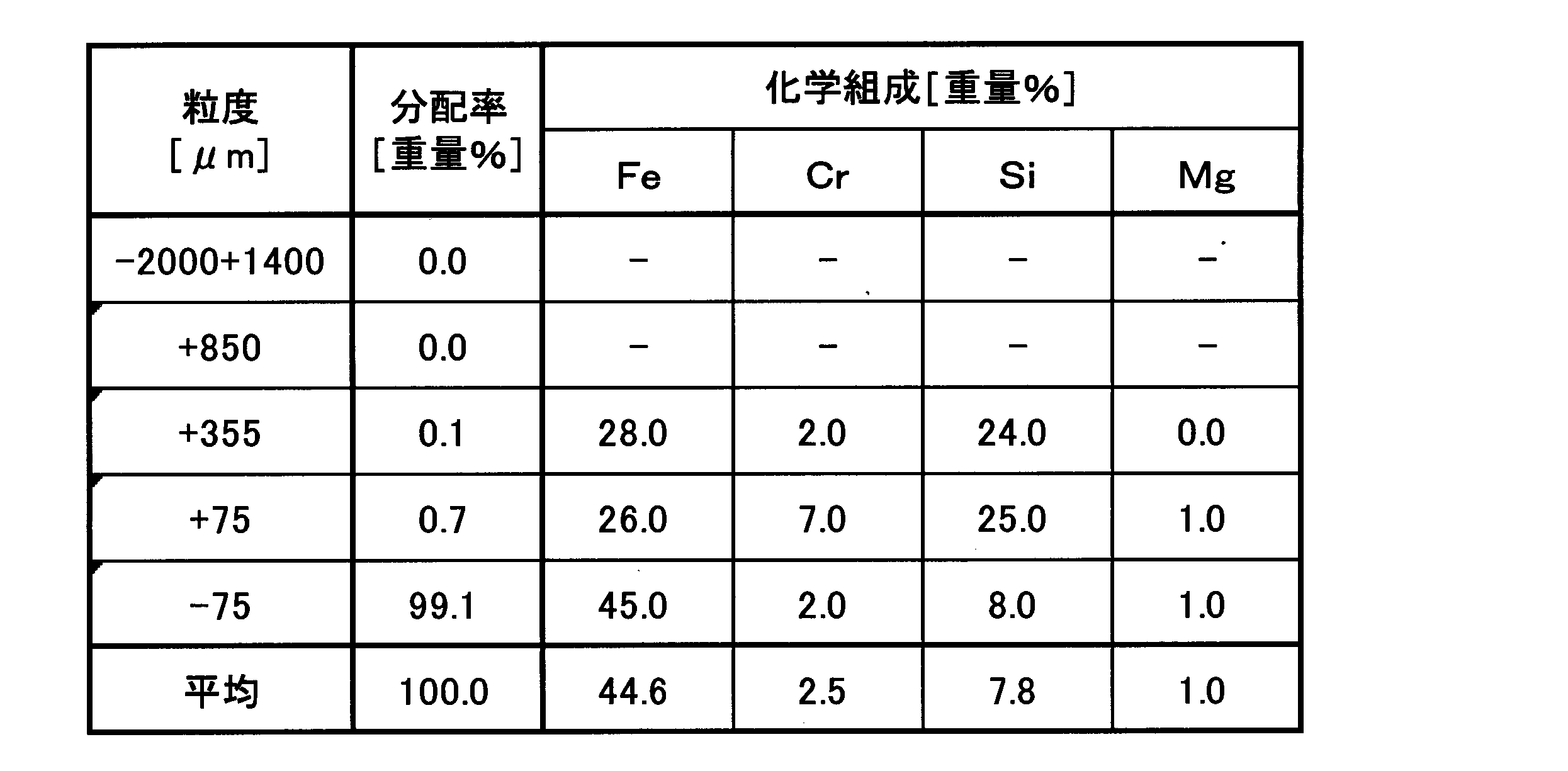
- Table 1 shows an example of the ore particle size distribution of the ore slurry obtained by crushing to a particle size of about 2 mm or less and the quality of each component in each particle size classification. From Table 1, it can be seen that chromium, silicon, magnesium and the like are concentrated in the coarse particle portion of 75 ⁇ m or more. On the other hand, it can be seen that iron is concentrated in the fine-grained portion of 75 ⁇ m or less.
- step (A) is a step of separating and recovering chromite in the ore slurry produced from the ore treatment step. It is also possible to separate and remove silica minerals or mineral particles such as silicicite ore as an intermediate in the process.
- (A) process can also be implemented by including in an ore processing process, or following an ore processing process.
- the method of the step (A) is not particularly limited, and methods using various physical separation means for separating chromite from the ore slurry can be applied, and among these, ore particles constituting the ore slurry
- chromite for example, 41 to 50 wt% Cr 2 O 3 , which is easy to recycle after separating and recovering chromite from the analysis of the distribution state of each component in the wet process, including a specific gravity separation method
- the classification particle size in this classification is not particularly limited as long as goethite containing nickel in the fine-grained portion can be efficiently separated, and is preferably selected from the range of 20 to 150 ⁇ m, more preferably 45 to 75 ⁇ m. That is, the lower limit of the classification point that can be industrially implemented is approximately 20 ⁇ m, and if the classification particle size is less than 20 ⁇ m, the concentration of chromite to the coarse portion is insufficient and the ore slurry used in the leaching step The nickel will be lost. On the other hand, when the classified particle size exceeds 150 ⁇ m, removal of silica minerals, chromite, and silicic clay is insufficient at the fine-grained portion.
- the classification method is not particularly limited, but it is desirable to select a cyclone classification capable of high performance and mass processing.
- the specific gravity of chromite is known to be greater than that of iron hydroxide such as goethite, and coarse and high specific gravity chromite and fine and low specific gravity can be separated efficiently by cyclone. It is.
- the operating pressure of the cyclone is preferably 0.1 to 0.3 MPa in consideration of separation performance and processing speed. It is desirable to adjust the shape of the cyclone so that the underflow pulp content is 50% by weight or more.
- the pulp content of the ore slurry used for the cyclone is not particularly limited, but is preferably 10 to 30% by weight, more preferably 15 to 20% by weight.
- the cyclone can be separated by 10% by weight or less, but it requires a large amount of water and is also disadvantageous for sedimentation and concentration in the subsequent process.
- it exceeds 30% by weight the viscosity of the slurry increases and separation may be difficult. That is, it is preferable to set the pulp content after the ore treatment step to 10 to 30% by weight of the above range, since it is not necessary to supply water again and a tank for dilution is unnecessary.
- chromite is further concentrated by a specific gravity separator.
- the specific gravity separator to be used is not particularly limited, but it is preferable to select at least one of a shaking table, a density separator, and a spiral concentrator, and at least one of a density separator and a spiral concentrator suitable for mass processing. More preferably, one type is selected.
- the pulp content of the slurry supplied thereto is preferably more than 15% by weight and less than 35% by weight, more preferably more than 20% by weight and less than 30% by weight. If it is 15% by weight or less, the separation performance may be deteriorated. If it is 35% by weight or more, the particle flow stays on the chromite concentration side (inside) during the separation by the spiral concentrator, and buildup occurs. , Separation may not be performed sufficiently. Furthermore, when a spiral concentrator is used, the chromite recovery rate is increased by spirally treating chromite (outside) concentrated to 15 wt% or more and 40 wt% or less several times.
- Teeter Water refers to water for floating the ore particles in the density separator. The ore particles are lifted to form a fluidized bed and collect heavy particles in the lower layer. Teeter Water is sometimes referred to as Fluidization Water.
- the amount of Teeter Water is less than 0.5, the effect of interference drop is reduced, and specific gravity separation is not performed efficiently.
- it is larger than 7.0, the chromite particles may be raised and lost to the overflow side.
- the amount of chromite in the slurry supplied to the leaching process is increased, which is disadvantageous not only from the recovery of chromite but also from the viewpoint of reducing the quality of Cr in hematite.
- the quality of Cr 2 O 3 is increased by treating the slurry several times with a density separator.
- this specific gravity separation alone can be concentrated up to 41 to 50% by weight in the chromite Cr 2 O 3 grade, but in order to concentrate to a higher concentration, the magnetite contained in a trace amount can be separated and removed. desirable. Since the specific gravity of the magnetite to be removed is very close to that of chromite, magnetic separation is used.
- the magnetic field strength is not particularly limited, and is preferably in the range of 200 [Oe] to 2000 [Oe], although it varies depending on the speed of the belt, the thickness of the belt, and other devices.
- the magnetic field strength is less than 200 [Oe]
- the magnetic field may be too weak, and separation and removal of magnetite may be insufficient.
- it exceeds 2000 [Oe] there is no problem in removing the magnetite, but even chromite may be magnetized, and magnetic separation will not be successful. It is particularly desirable to use a low magnetic field magnetic separator.
- the chromite obtained by these treatments is classified.
- non-mag slurry obtained by low magnetic field magnetic separation is classified by a classifier equipped with 53 ⁇ m and 300 ⁇ m meshes, so that the grade of Cr 2 O 3 obtained by this classification can be increased. it can.
- the leaching step consists of a leach residue and a leachate by adding sulfuric acid to the ore slurry obtained through the ore treatment step and the step (A) and stirring at a temperature of 220 to 280 ° C. It is a process of forming a leaching slurry. In this process, a preheater, an autoclave, and a flash tank are used as main equipment.
- sulfuric acid such as nickel or cobalt is obtained by the leaching reaction represented by the following reaction formulas (1) to (3) and the high temperature thermal hydrolysis reaction represented by the reaction formulas (4) to (5).
- Leaching as a salt and immobilization of the leached iron sulfate as hematite are performed.
- the leaching slurry obtained usually contains divalent and trivalent iron ions in addition to nickel and cobalt.
- the reaction temperature in the leaching step is 220 to 280 ° C, preferably 240 to 270 ° C. That is, by performing the reaction in this temperature range, iron is fixed as hematite. If the reaction temperature is less than 220 ° C., the rate of the high-temperature thermal hydrolysis reaction is slow, so iron remains dissolved in the reaction solution, increasing the load of the liquid for removing iron and greatly separating it from nickel. It becomes difficult. On the other hand, if the temperature exceeds 280 ° C., the high-temperature thermal hydrolysis reaction itself is promoted, but it is not only difficult to select the material of the container used for the high-temperature pressure leaching, but it is not possible because the steam cost for the temperature rise increases. Is appropriate.
- the amount of sulfuric acid used in the leaching process is not particularly limited, and is slightly more than the chemical equivalent required for iron in the ore to be leached and converted to hematite, for example, 300 to 1 per ton of ore. 400 kg is used. In particular, when the amount of sulfuric acid added per ton of ore exceeds 400 kg, the sulfuric acid cost and the neutralizing agent cost in the subsequent process increase, which is not preferable.
- the amount of sulfuric acid used from the leaching step product is set so that the concentration of free sulfuric acid at the end of leaching is 25 to 50 g / L, preferably 35 to 45 g / L.
- the true density of the leaching residue is increased and a high density leaching residue is stably produced, and the solid-liquid separation property of the slurry is improved.
- Simplification can be performed. That is, when the concentration is less than 25 g / L, when the slurry containing the leaching residue is settled, the sediment concentration of solids becomes incomplete, and the suspended solids remain in the supernatant. This is because the reaction rate of high-temperature thermal hydrolysis is slow, the dehydration of iron hydroxide does not proceed sufficiently, and hematite with a low true density is formed. On the other hand, if the concentration exceeds 50 g / L, it is necessary to improve the durability of the leaching equipment, and the amount of neutralizing agent used for neutralizing the acid is remarkably increased. It will be disadvantageous.
- Solid-liquid separation step is a step in which the leaching slurry formed in the previous leaching step is washed in multiple stages to obtain a leaching solution containing nickel and cobalt and a leaching residue. As a result, nickel or the like that adheres to the leaching residue and is discarded is recovered in the leaching solution.
- Step (B-1) Neutralization step [(B-1) step and (B-2) step] (4-1) Neutralization step 1 [Treatment of leachate] Step (B-1)
- This step (B-1) neutralizes the leachate 11 separated in the previous solid-liquid separation step, while suppressing oxidation of the leachate 11 obtained in the leach step.
- (B-1) of the neutralized starch slurry containing trivalent iron by adding a neutralizing agent (pH adjusting agent) so that the pH is 4 or less, preferably 3.2 to 3.8.
- a process residue 26 and a mother liquid (1) 14 for recovering nickel are formed.
- the excess acid used in the leaching step is neutralized and trivalent iron ions remaining in the leaching solution are removed.
- Mg-based alkalis such as Mg (OH) 2 that does not contain Ca
- Mg-based neutralizers such as MgO that dissolves in the leachate and show alkalinity as the neutralizing agent.
- a neutralizing agent containing Ca such as CaCO 3
- gypsum is produced. Since the (B-1) step residue 26 of the neutralized starch slurry generated in this step is partially returned to the solid-liquid separation step and repeated, there is a concern that gypsum is mixed into the leaching residue slurry. Since it is a small amount, it does not significantly affect the quality of hematite. Here, there is no problem even if a Ca-based neutralizing agent is used.
- Zinc removal step In this zinc removal step, hydrogen sulfide gas is blown into the mother liquor obtained in the previous step prior to the step of separating nickel and cobalt as sulfides to produce sulfide containing zinc. It is a step of forming a zinc sulfide starch slurry and a mother liquor for nickel and cobalt recovery. This suppresses the speed of the sulfidation reaction by creating weak conditions during the sulfidation reaction, and selectively removes zinc by suppressing the coprecipitation of nickel, which has a higher concentration than zinc. is there.
- the obtained zinc sulfide starch slurry can be sent to the final neutralization step (7) and processed in the same manner as the neutralized starch slurry obtained in the neutralization step.
- [6] Sulfurization step In this sulfidation step, hydrogen sulfide is blown into the mother liquor (2) for recovering nickel and cobalt obtained in the dezincification step, and mixed sulfide (zinc sulfide starch) 17 containing nickel and cobalt and This is a process for generating the poor liquid 18.
- the obtained poor solution 18 has a pH of about 1 to 3 and contains slight amounts of nickel and cobalt, which are recovery losses, in addition to impurities such as iron, magnesium, and manganese that are contained without being sulfided. It is used as leaching residue washing water in the solid-liquid separation step and neutralization residue washing water produced in the neutralization step.
- Step (B-2) Neutralization step 2 [Treatment of leach residue slurry]
- Step (B-2) a part of the leaching residue (leaching residue slurry: indicated by reference numeral 12 in FIG. 1) produced from the solid-liquid separation step is removed with Mg (OH) 2 or the like.
- Mg-based neutralizing agent such as Mg-based alkali or MgO to recover hematite particles.
- the method for the step (B-2) is not particularly limited, but a Ca-based alkali is not used as the neutralizing agent.
- CaCO 3 is used as a neutralizing agent, it reacts with the attached sulfuric acid to produce gypsum.
- MgSO 4 Since the solubility of this gypsum is small, it precipitates as a solid and raises the sulfur quality in the residue.
- MgSO 4 has a high solubility, so that it does not easily precipitate as a solid and is effective in reducing sulfur. Accordingly, Mg (OH) 2 which is an Mg-based alkali is preferable as the neutralizing agent, but an Mg-based neutralizing agent such as MgO may be used.
- Table 2 shows an example of the ore particle size distribution of the leaching residue obtained when the ore slurry obtained by crushing to a particle size of about 2 mm or less and the grade of each component in each particle size classification.
- the particles containing iron at a high content are finer than the particles containing high content of chromium, silicon, etc., and chromium, silicon, etc. are removed by sorting means such as a classification method. It can be separated from the coarse portion containing a high content and discharged out of the system to recover hematite as a resource.
- sorting means such as a classification method. It can be separated from the coarse portion containing a high content and discharged out of the system to recover hematite as a resource.
- the classification method treatment with a cyclone or the like capable of mass treatment is preferable.
- This final neutralization step includes (B-2) of (B-2) post-treatment liquid 27 obtained in step (B-2) and leaching residue slurry 12 after the solid-liquid separation step. 2) Add the slurry not treated in step and (B-1) step residue 26, or, if necessary, the slurry of zinc sulfide starch 15 obtained in the zinc removal step. In this step, the limestone slurry and slaked lime slurry are added and the pH is adjusted to about 8 to 9, whereby the metal ions in the liquid are precipitated as neutralized starch to obtain the final neutralized residue 19. The obtained final neutralization residue 19 is stored in the tailing dam 20.
- the present invention will be further described below with reference to examples, but the present invention is not limited to these examples.
- the metal is analyzed using a fluorescent X-ray analysis method or an ICP emission analysis method.
- step for the ore slurry 9 is classified by hydrocyclone according to the flow chart shown in FIG. One specific gravity separation was performed in the order of the separator.
- a hydrocyclone manufactured by Ataca Daiki Co., Ltd., MD-9 type
- ore slurry whose composition is shown in Table 3 was classified.
- classification was performed under the conditions of a slurry concentration of 15 wt%, a slurry temperature of room temperature, and an operating pressure of 0.2 MPa.
- composition of the ore slurry and the hydrocyclone underflow are also shown in Table 3.
- the unit in the table below is weight%.
- the hydrocyclone U / F (slurry concentration: 33% by weight) was mixed with a density separator (Density Separator: Autotec Inc., “Tanksizer TS-Lab”, tank inner diameter 228). .6 mm).
- the supply rate was 56 [kg / Hr], and the temperature of the slurry was normal temperature.
- the amount of Teeter Water at this time was 6.9 [m 3 ⁇ h ⁇ 1 / m 2 ], and Set Point (set value of density meter) was 20.
- the composition of the density separator feed (hydrocyclone U / F) and underflow (density separator U / F) is shown in Table 4.
- the density separator U / F (1) (slurry concentration 75% by weight) obtained with the density separator is diluted with water to make the slurry concentration 25% by weight.
- Spiral Concentrator manufactured by Autotec Inc., “MC7000”. The test results are shown in Table 6.
- the ore slurry can be concentrated to a concentration exceeding the Cr 2 O 3 grade of commercially available chromite by treating the ore slurry in the order of hydrocyclone, density separator 2 treatment, and spiral concentrator.
- the recovery rate of the obtained chromite was 42.5% by weight.
- the recovery rate was calculated by the following formula (6).
- classification treatment was performed on the chromite obtained by the low magnetic field magnetic separation process as shown below.
- the Non-Mag slurry obtained by the low magnetic field magnetic separation was subjected to classification treatment with a classifier (manufactured by DALTON Co., Ltd .: vibrating sieve 702CB) equipped with 53 ⁇ m and 300 ⁇ m meshes.
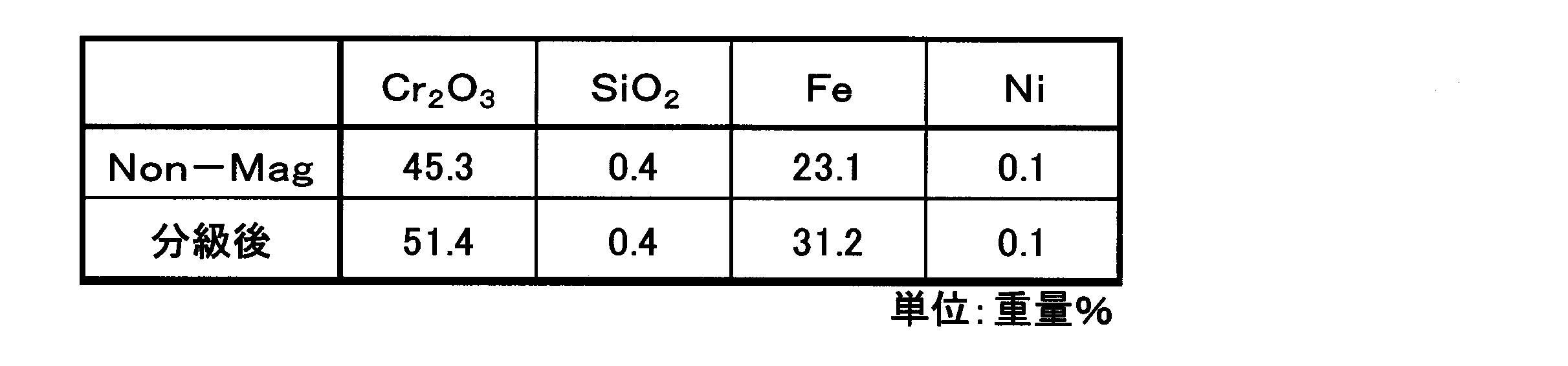
- the results are shown in Table 8. From Table 8, Cr 2 O 3 obtained by classification treatment rose to 51.4% by weight, compared to 45.3% by weight in the feed.
- Example 1 Fe increased from 23.1 wt% to 31.2 wt%. From the above results, it can be said that the smelting method of the present invention shown in Example 1 can be concentrated to a concentration exceeding the Cr 2 O 3 grade of commercially available chromite. The recovery of chromite obtained in Example 1 was 19%. The recovery rate was calculated by equation (6).
- step (A) for the ore slurry is repeated in the density concentration separation by the density separator as shown in the flow chart of the step (A) in FIG.
- the specific gravity separation used was performed.
- a hydrocyclone manufactured by Ataca Daiki Co., Ltd., MD-9 type
- ore slurry whose composition is shown in Table 9 was classified.
- the slurry concentration was 15 wt%
- the temperature of the slurry was normal temperature
- the operating pressure was 0.2 MPa
- classification was performed.
- Table 9 shows the composition of the ore slurry and the composition of the hydrocyclone U / F. The unit in the table below is weight%.
- hydrocyclone U / F (slurry concentration: 33% by weight) was supplied to a density separator (Density Separator: Autotec Inc., “Tanksizer TS-Lab”, tank inner diameter 228.6 mm).
- the supply rate was 56 [kg / Hr], and the temperature of the slurry was normal temperature.
- the amount of Teeter Water at this time was 6.9 [m 3 ⁇ h ⁇ 1 / m 2 ], and Set Point (set value of density meter) was 20.
- the composition of the feed (hydrocyclone U / F) and underflow (density separator U / F (1)) of the density separator (1) is shown in Table 10.
- the density separator U / F (1) (slurry concentration 75 wt%) was diluted with water to a slurry concentration of 40 wt%, and the density separator treatment was performed again.
- Density Separator (2) Feed (Density Separator U / F (1) obtained by the first Density Separator process) and Underflow (Density Separator U / F (2) obtained by the second Density Separator process)
- the composition of is shown in Table 11.
- the density separator U / F (2) (slurry concentration 75% by weight) obtained from the density separator (2) was diluted with water to a slurry concentration of 25% by weight, and a spiral separator ((Spiral Concentrator: Autotec) Inc., “MC7000”), a spiral test was performed. The results of the spiral test are shown in Table 12.
- “Concentrate” obtained in the two table tests was mixed to dilute the slurry concentration to 20% by weight, and a low magnetic field magnetic separator (manufactured by Autotec Inc., “ Inprosys benchtop LIMS ”), a magnetized material (Mag) and a non-magnetized material (Non-mag) were obtained. The results are shown in Table 14.
- the ore slurry can be concentrated to a concentration exceeding the Cr 2 O 3 grade of commercially available chromite by treating the ore slurry in the order of hydrocyclone, density separator 2 treatment, and spiral concentrator. Further, the recovery rate of the obtained chromite was 44%. The recovery rate was calculated by the formula (6) in the same manner as in Example 1.
- classification treatment was performed on the chromite obtained by the low magnetic field magnetic separation process as shown below.
- the Non-Mag slurry obtained by the low magnetic field magnetic separation was subjected to classification treatment with a classifier (manufactured by DALTON Co., Ltd .: vibrating sieve 702CB) equipped with 53 ⁇ m and 300 ⁇ m meshes.
- a classifier manufactured by DALTON Co., Ltd .: vibrating sieve 702CB
- Example 2 the smelting method of the present invention shown in Example 2 can be concentrated to a concentration exceeding the Cr 2 O 3 grade of commercially available chromite.
- the recovery rate of chromite obtained in Example 2 was 20%.
- the recovery rate was calculated by the formula (6) in the same manner as in Example 1.
- Comparative Example 1 In accordance with the implementation flow in Comparative Example 1 shown in FIG. 5, after classification by hydrocyclone, instead of the specific gravity separation process of Example 1, separation by the size of solids contained in the ore slurry using a high mesh separator Went.
- a classifier ore slurry was classified using a hydrocyclone (manufactured by Tataka Taiki Co., Ltd., “MD-9”).
- the slurry concentration was 9.8% by weight
- the temperature of the slurry was room temperature
- classification was performed under an operating pressure of 0.22 MPa.
- Hydrocyclone underflow (hydrocyclone U / F) having a slurry concentration of 33% by weight is diluted to a slurry concentration of 4.9% by weight, and a high mesh separator (“KUC-612S” manufactured by Kiko Co., Ltd.) I was charged.
- the supply speed to the high mesh separator is 0.98 [m 3 / hour]
- the rotation speed of the bucket is 0.8 rpm
- the bucket length is 75 mm
- the bucket has 4 mm diameter holes opened at a pitch of 6 mm. 40%.
- the amount of washing water was 6 m 3 / hour.
- Table 16 The composition of the ore slurry and hydrocyclone underflow (hydrocyclone U / F) and the composition of the high mesh separator underflow (high mesh separator U / F) are shown in Table 16.
- the Cr 2 O 3 grade of the ore slurry is 4.1% by weight and the hydrocyclone coarse part (hydrocyclone-U / F) is 13.0% by weight, and the high mesh separator coarse part (high Although it was concentrated to 19.1% by weight with a mesh separator-U / F), it did not reach the intended commercial level composition. In this step, there was no problem in the concentration with the hydrocyclone, but it can be determined that the concentration with the high mesh separator is insufficient.
- the Cr grade of the high mesh separator underflow (high mesh separator-U / F) is 14.2% by weight (20.7% by weight; Cr 2 O 3 ), and the hydrocyclone underflow (hydrocyclone).
- U / F was lower than 16.7% by weight (24.4% by weight; Cr 2 O 3 ), and it was revealed that no specific gravity separation was achieved. From this result, the high-mesh separator only performs the slime removal work and does not perform the specific gravity separation work. Thus, it can be seen that chromite having commercially available Cr 2 O 3 grade cannot be concentrated unless specific gravity separation is performed.
- Example 1 The hydrocyclone overflow of Example 1 and the density separator overflow were charged into the autoclave at a solid weight ratio of 77:15, 98% sulfuric acid was added thereto, and hot sulfuric acid leaching was performed under the following conditions.
- a leaching slurry 10 was produced. Furthermore, the produced leaching slurry was separated into a leaching solution 11 and a leaching residue slurry 12 by a solid-liquid separation step.
- a neutralization agent Mg (OH) 2 slurry having a concentration of 20 wt% is added to the leaching residue slurry 12, and a pH of 2. Neutralize to 5 Next, this slurry was subjected to solid-liquid separation with 5C filter paper, and further Mg (OH) 2 slurry was added until pH 6 was reached, and then further solid-liquid separated with 5C filter paper.
- the final neutralization residue obtained had a Cr 2 O 3 grade of 0.9% by weight. Due to the high solubility of the resulting MgSO 4 , the sulfur quality of the residue was 0.53% by weight.
- Example 2 (Comparative Example 2) The ore slurry of Example 1 was charged into an autoclave without being treated with a hydrocyclone and a density separator, and was otherwise treated in the same manner as in Example 3. As a result, Cr 2 O 3 grade of the obtained final neutralization residue was obtained. Was 2.1% by weight. Due to the high solubility of the resulting MgSO 4 , the sulfur quality of the residue was 0.53% by weight.
- Example 3 the chromite in the ore slurry is separated and removed by first classifying with a hydrocyclone and then treating with a density separator which is one of specific gravity separators.
- the Cr 2 O 3 grade in the residue could be halved.
- Example 3 (Comparative Example 3) In the same manner as in Example 3, a leaching residue slurry 12 was prepared, and a slaked lime slurry having a concentration of 25% by weight was added as a neutralizing agent to the total amount, and neutralized to a pH of 8.5 at 60 ° C. Ions were precipitated as starch, and a neutralized residue and a neutralized post-treatment liquid were obtained by solid-liquid separation.
- the neutralized residue was classified into a cyclone to separate hematite 28. After adding the slaked lime slurry having a concentration of 25% by weight to the mixed solution obtained by mixing the remaining neutralization residue from which hematite 28 has been separated and the post-neutralization treatment liquid, the solid-liquid separation with 5C filter paper is repeated to obtain the final neutralization residue. Obtained.
- the final neutralized residue obtained had a Cr 2 O 3 grade of 0.8% by weight. Due to the low solubility of CaSO 4 produced, the sulfur quality of the residue was 5.72% by weight and the Ca quality was 8.49.
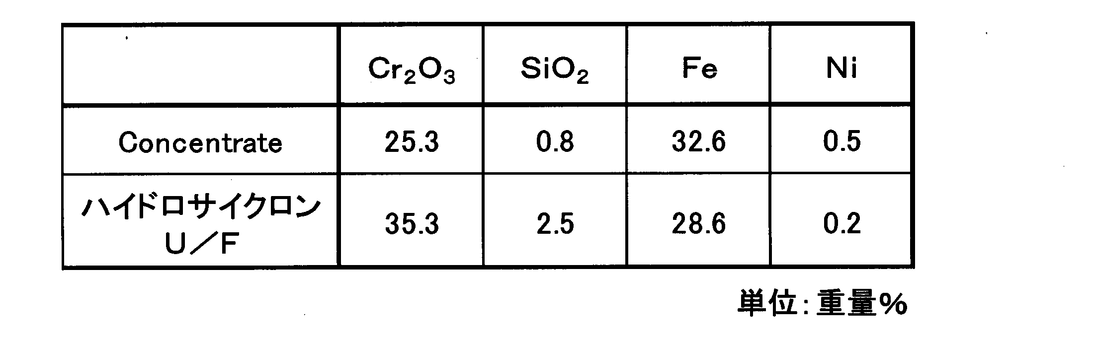
- Comparative Example 4 As shown in the implementation flow diagram of Comparative Example 4 in FIG. 6, the ore slurry is subjected to 1 specific gravity separation in the same manner as in Example 1 without being classified by hydrocyclone, and finally, the classification treatment by hydrocyclone is performed. A separation test was performed under the same conditions as in Example 1 except that the test was performed. Table 18 shows the results of the specific gravity separation treatment of the ore that has not been subjected to the classification treatment with the hydrocyclone, using a density separator.
- the Cr 2 O 3 concentration by the density separator is as high as the underflow (see Table 4, Density Separator U / F) where the classification treatment was performed and the feed was processed. did not become.
- Table 19 shows the results of separating the density separator U / F with a spiral separator.
- the Cr 2 O 3 concentration was 25.3% by weight and not more than 41% by weight even when the specific gravity separation treatment with a spiral separator was performed. This is because the coarseness and fineness cannot be separated by the density separator, so that the slurry viscosity is high and the spiral effect cannot be exhibited.
- the nickel oxide ore hydrometallurgy method of the present invention is suitable as a smelting method based on high pressure leaching utilized in the field of nickel oxide ore hydrometallurgy.
Landscapes
- Chemical & Material Sciences (AREA)
- Engineering & Computer Science (AREA)
- Organic Chemistry (AREA)
- Metallurgy (AREA)
- Mechanical Engineering (AREA)
- Materials Engineering (AREA)
- Manufacturing & Machinery (AREA)
- Geology (AREA)
- Life Sciences & Earth Sciences (AREA)
- Geochemistry & Mineralogy (AREA)
- General Life Sciences & Earth Sciences (AREA)
- Environmental & Geological Engineering (AREA)
- Chemical Kinetics & Catalysis (AREA)
- General Chemical & Material Sciences (AREA)
- Inorganic Chemistry (AREA)
- Manufacture And Refinement Of Metals (AREA)
Abstract
Description
この高圧酸浸出法は、従来の一般的なニッケル酸化鉱石の製錬方法である乾式製錬法と異なり、還元工程、乾燥工程等の乾式工程を持たないために、エネルギーコスト的に有利であり、今後も低品位ニッケル酸化鉱石の製錬方法として有力な技術であると見られている。
このため、製錬プロセスとしての完成度を上げるため、高温加圧下での浸出工程を中心として、ニッケル及びコバルトの浸出率の向上、浸出液の浄液、操業資材使用量の低減等に関し様々な提案がなされている。
工程(b):工程(a)で得られた常圧浸出残留物を、高温高圧下の酸化性雰囲気下で硫酸と反応させて加圧酸浸出液を得る。
工程(c):工程(a)で得られた常圧浸出液に中和剤を加えて中和し、次いで硫化アルカリ化合物を添加し、浸出液中のニッケル及びコバルトを硫化物として回収する。
そこで、これらの問題点を解決するため、高温加圧下での浸出を利用する他のプロセスとして、下記(1)~(4)からなる工程を含む方法(例えば、特許文献2参照。)が提案されている。
(2)固液分離工程:先の浸出工程で得た浸出スラリーを、多段階のシックナーを用いて洗浄し、ニッケル及びコバルトを含む浸出液と浸出残渣とに分離する。
(3)中和工程:固液分離工程で得た浸出液の酸化を抑制しながら、炭酸カルシウムを用いてpHが4以下となるよう調整し、3価の鉄を含有する中和澱物を生成し、中和澱物スラリーとニッケル回収用母液とに分離する。
(4)硫化工程:中和工程で得たニッケル回収用母液に硫化水素ガスを吹きこみ、ニッケル及びコバルトを含有する硫化物を生成し、貧液と分離する。
図2は、特許文献2に開示されるニッケル酸化鉱石の湿式製錬方法に基づく実用プラントの一例における製錬工程図である。
図2において、ニッケル酸化鉱石8は、最初に、(1)鉱石処理工程で水との混合液を形成し、次いで、その混合液からの異物除去、及び鉱石粒度調整を行い、鉱石スラリー9を形成する。
この得られた浸出スラリー10は、(3)固液分離工程に付され、多段洗浄された後、ニッケル及びコバルトを含む浸出液11と浸出残渣スラリー12に分離される。
分離された一方の母液(1)14は、硫化剤を添加する(5)亜鉛除去工程に付され、硫化亜鉛を含む硫化亜鉛澱物15とニッケル回収用の母液(2)16とに分離される。
他方の母液(2)16は、(6)硫化工程に付され、ニッケル及びコバルトを含む混合硫化物17とニッケル等が除去された貧液18に分離される。なお、貧液18は、(3)固液分離工程における浸出残渣の洗浄水として使用される。
最後に、浸出残渣スラリー12は、余剰の貧液18とともに、(7)最終中和工程に付され、中和処理され、最終中和残渣19は、テーリングダム20に貯留される。
さらに、中和澱物スラリーを固液分離工程へ送れば、ニッケルのロスを低減することができるので、より有利であるとされている。
第一に設備の磨耗の抑制が挙げられる。
ニッケル酸化鉱石は、スラリーとして各工程間を搬送されるが、搬送されるスラリーによる設備材料の磨耗の促進が著しく、とりわけ浸出工程における配管、ポンプ等の設備では補修頻度が高く、メンテナンスコストの上昇とプラント稼働率の低下の大きな原因となっている。
固液分離工程で得られる浸出残渣は、硫化工程から産出する余剰の貧液と合一され、これに石灰石スラリー又は消石灰スラリーを添加する中和処理により無害化される。
この最終的な中和処理工程(以下、最終中和工程と呼称する場合がある。)から産出される最終中和残渣は、テーリングダムで貯留されるが、この最終中和残渣には、浸出残渣中のヘマタイト、クロマイト等の不純物成分のほか、中和処理により形成される石膏を含有するため資源化できず、テーリングダムの建設及び維持管理のための大きなコスト負担があった。
さらに、上記課題を、効果的かつ経済的に解決するためには、鉱石又は浸出残渣に含まれる不純物成分を効率的に分離回収することが有効な手段であり、これら不純物成分を資源化して有効活用することも求められていた。
記
(A)工程:前記鉱石処理工程から産出する鉱石スラリー中のクロマイト粒子を、比重分離法を含む回収プロセスにより分離した後、分級処理を行い、高濃度クロマイト濃縮物を回収する工程。
記
(A)工程:前記鉱石処理工程から産出する鉱石スラリー中のクロマイト粒子を、比重分離法を含む回収プロセスにより分離した後、分級処理を行い、高濃度クロマイト濃縮物を回収する工程。
(B-1)工程:前記(A)工程を経てクロマイト粒子を分離してCr品位の下がった鉱石スラリーを、前記浸出工程、固液分離工程の順に処理して生成した浸出液を中和処理する中和工程であって、
前記中和処理に際してCa系又はMg系中和剤の少なくとも一種以上を用いて中和する工程。
(B-2)工程:前記(A)工程を経てクロマイト粒子を分離してCr品位の下がった鉱石スラリーを、前記浸出工程、固液分離工程の順に処理して生成した浸出残渣スラリーを中和処理する中和工程であって、
前記中和処理に際してMg系中和剤を用いて中和処理し、前記浸出残渣スラリーからヘマタイト粒子を回収する工程。
記
(A)工程:前記鉱石処理工程から産出する鉱石スラリー中のクロマイト粒子を、比重分離法を含む回収プロセスにより分離した後、分級処理を行い、高濃度クロマイト濃縮物を回収する工程。
(B-1)工程:前記(A)工程を経てクロマイト粒子を分離してCr品位の下がった鉱石スラリーを、前記浸出工程、固液分離工程の順に処理して生成した浸出液を中和処理する中和工程であって、
前記中和処理に際してCa系又はMg系中和剤の少なくとも一種以上を用いて中和する工程。
(B-2)工程:前記(A)工程を経てクロマイト粒子を分離してCr品位の下がった鉱石スラリーを、前記浸出工程、固液分離工程の順に処理して生成した浸出残渣スラリーを中和処理する中和工程であって、
前記中和処理に際してMg系中和剤を用いて中和処理し、前記浸出残渣スラリーからヘマタイト粒子を回収する工程。
また、湿式製錬前にクロマイトを分離するので、浸出残渣量の減少が期待でき、最終中和残渣量を低減することもできる。さらに、分離したクロマイトを濃縮すれば、資源として有効活用することも可能である。
・(A)工程
鉱石処理工程を経てから産出する鉱石スラリー中のクロマイト粒子を、比重分離法を含む回収プロセスにより分離した後、分級処理を行い、高濃度のクロマイト濃縮物を回収する工程である。
(B-1)工程
(A)工程を経てCr品位の下がった鉱石スラリーを、浸出工程、固液分離工程で処理し、固液分離工程後の浸出液の中和を、Mg(OH)2、MgOなどのMg系中和剤やCaCO3、Ca(OH)2などのCa系中和剤で行うものである。
(A)工程を経てCr品位の下がった鉱石スラリーを、浸出工程、固液分離工程で処理し、固液分離工程後の浸出残渣スラリーの中和を、Mg(OH)2、MgOなどのMg系中和剤で行い、ヘマタイト粒子を回収するものである。
この(A)工程の採用は、前工程の鉱石処理工程から産出する鉱石スラリー中のクロマイトを含む粒子を分離回収することにより、鉱石スラリーの輸送時の配管、ポンプ等の設備の磨耗を抑制する効果を付与するものである。
さらに、分離回収したクロマイトを、十分濃縮することが出来れば、資源として有効活用することも可能である。
なぜなら、最終中和残渣に含まれるイオウ(石膏;硫酸カルシウム)、クロム(クロマイト)等は、銑鉄中への微量成分の分配、鉄鋼製品の品質等に影響する成分であり、これら不純物元素の含有は抑制することが求められるからである。
図1は、本発明に係るニッケル酸化鉱石の湿式製錬方法による実施態様の一例を表す製錬工程図である。
図1に示すように、まずニッケル酸化鉱石8は、[1]鉱石処理工程で水との混合液を形成し、次いで、その混合液からの異物除去及び鉱石粒度調整が行われて鉱石スラリー9が形成される。
その後、この鉱石スラリー9は、新たに設けた(A)工程に付され、クロマイト23を分離回収する。一方のオートクレーブ供給スラリー22は、[2]浸出工程に供される。
形成された浸出スラリー10は、多段のシックナーなどを用いた[3]固液分離工程に供され、ニッケル及びコバルトを含む浸出液11と浸出残渣スラリー12とに分離される。
分離した一方の母液(1)14は、硫化剤を添加する[5]亜鉛除去工程に付され、硫化亜鉛を含む硫化亜鉛澱物15とニッケル回収用の母液(2)16とに分離される。
なお、貧液18は、[3]固液分離工程における浸出残渣の洗浄水として使用される他に、貧液18は、最終中和工程に供される場合もある。
その際、(B-2)工程後処理液27と(B-2)工程に供されなかった浸出残渣スラリー12は、[7]最終中和工程に供され、pH8~9程度に中和される。
得られた最終中和残渣19は、テーリングダム20に貯留される。
[1]鉱石処理工程及び(A)工程
鉱石処理工程は、異物除去及び鉱石粒度調整を行い、鉱石スラリーを形成する工程である。
この工程では、ニッケル酸化鉱石を、湿式篩等で篩い分けし、浸出工程で浸出できない異物、ポンプで流送困難な粒度の鉱石等を分離する。
通常、篩分け粒度は、2mm程度であり、それ以上の粒度の鉱石は、分別される。
篩分け処理を通過した鉱石によりスラリーが形成され、次いで沈降させて濃縮し、スラリー中の固体濃度(以下、スラリー濃度と称す)を調整したオートクレーブ供給スラリーを調製する。なお、スラリー濃度としては、通常、30~45重量%程度に調整すると良い。
このラテライト鉱のニッケル含有量は、通常、0.8~2.5重量%であり、ニッケルは水酸化物、又は含水ケイ苦土(ケイ酸マグネシウム)鉱物として含有される。
また、鉄の含有量は、10~50重量%であり、主として3価の水酸化物(ゲーサイト)の形態であるが、一部2価の鉄が含水ケイ苦土鉱物等に含有される。珪酸分は、石英、クリストバライト(無定形シリカ)等のシリカ鉱物及び含水ケイ苦土鉱物に含有されている。
さらに、クロム分の多くは、鉄又はマグネシウムを含むクロマイト鉱物として1~5重量%含有される。また、マグネシア分は、含水ケイ苦土鉱物のほか、未風化で硬度が高いニッケルをほとんど含有しないケイ苦土鉱物に含有される。
つまり、この鉱石処理工程から産出する鉱石スラリーには、一般的に浸出工程の配管、ポンプ等の設備の磨耗に大きな影響を及ぼすクロマイトが含まれていることになる。
そのため、鉱石処理工程で調製する鉱石スラリーから、クロマイトを事前に鉱石処理工程において分離回収しておくことが望ましい。
ニッケル酸化鉱石のEPMA観察では、クロム含有量の高い部分は、鉄含有量の高い部分とは独立した単独相として存在する比率が高く、かつ20~1000μmの粒径であるものが多い。
このことは、クロムを含む鉱物は、約20μm以上の粒子に多く含まれており、一方、ニッケル及び鉄を含む鉱物は、約20μm以下の粒子に多く含まれていることを示している。
なお、この時の解砕粒度としては、鉱石スラリーを形成する際の本来の目的を考慮して決められるが、約2mm以下が好ましい。
表1より、75μm以上の粗粒部に、クロム、珪素、マグネシウム等が濃縮されることが分かる。一方、75μm以下の細粒部には鉄が濃縮されることがわかる。

なお、(A)工程は、鉱石処理工程内に含めて実施する、或いは鉱石処理工程に続いて実施することもできる。
すなわち、表1に示すように、分級で濃縮できる品位には限界があり、分級だけでなく、比重差を利用した分離が必要となる。
すなわち、工業的に実施可能な分級点の下限は、おおむね20μmである上、この分級粒度が20μm未満では、粗粒部へのクロマイトの濃縮が不十分であるとともに、浸出工程で用いる鉱石スラリー中のニッケルがロスすることとなる。一方、分級粒度が150μmを超えると、細粒部でシリカ鉱物、クロマイト及びケイ苦土鉱の除去が不十分となってしまう。
一般に、クロマイトの比重はゲーサイト等の水酸化鉄のそれよりも大きいことが知られており、粗大で比重が大きいクロマイトと微細で比重が小さいゲーサイトは、サイクロンにより効率良く分離することが可能である。
サイクロンの形状は、アンダーフローのパルプコンテントが50重量%以上となるように形状を調整することが望ましい。
サイクロンの分離としては10重量%以下でも可能だが、水を大量に必要とする上、後工程の沈降濃縮にも不利である。また、30重量%を超えるとスラリーの粘度が上昇し、分離が困難になる場合がある。
すなわち、鉱石処理工程後のパルプコンテントを上記範囲の10~30重量%に設定すれば、更に新たに水を供給する必要がなく、希釈のためのタンクも不要になるため、好ましい。
使用する比重分離装置は、特に限定されるものではないが、シェーキングテーブル、デンシティ セパレーター、スパイラルコンセントレーターの少なくとも1種を選択することが好ましく、大量処理に適したデンシティ セパレーター、スパイラルコンセントレーターの少なくとも1種を選択することが更に好ましい。
15重量%以下であると、分離性能が悪化する場合があり、35重量%以上であると、スパイラルコンセントレーターで分離中にクロマイト濃縮側(内側)で粒子の流れが滞留してビルドアップが起こり、分離が十分に行われなくなる場合がある。
更に、スパイラルコンセントレーターを用いる場合には、15重量%以上40重量%以下に濃縮されたクロマイト(外側)を数回スパイラル処理することで、クロマイト回収率が高くなる。
ここで、Teeter Waterとは、デンシティ セパレーター内で上記鉱石粒子を浮き上がらせるための水をいう。前記鉱石粒子を浮き上がらせて流動層を形成させて重い粒子を下層に集める。Teeter WaterはFluidization Waterと呼ぶこともある。
一方、7.0より大きいと、クロマイト粒子まで上昇させ、オーバーフロー側に損失する場合がある。この場合、浸出工程に供給されるスラリー中のクロマイトが多くなり、クロマイトの回収のみならず、ヘマタイト中Cr品位低減の観点からも不利になる。
更に、デンシティ セパレーターでスラリーを数回処理することで、Cr2O3品位は上昇する。
除去するマグネタイトの比重は、クロマイトの比重に極めて近いので磁気分離を利用する。
特に望ましくは、低磁界磁力選鉱機を使用すると良い。
例えば、低磁界磁力選鉱で得られたNon-Magスラリーを、53μmと300μmのメッシュを備えた分級装置で分級処理を行うことによって、この分級処理により得られるCr2O3品位を上昇させることができる。
浸出工程は、鉱石処理工程及び(A)工程を経て得られた鉱石スラリーに、硫酸を添加して220~280℃の温度下で撹拌処理して、浸出残渣と浸出液からなる浸出スラリーを形成する工程である。この工程では、主要設備として、プレヒーター、オートクレーブ、及びフラッシュタンクが用いられる。
しかしながら、鉄イオンの固定化は、完全には進行しないので得られる浸出スラリーの液部分には、ニッケル、コバルト等のほか、2価と3価の鉄イオンが含まれるのが通常である。


すなわち、この温度範囲で反応を行うことにより、鉄はヘマタイトとして固定される。
反応温度が220℃未満では、高温熱加水分解反応の速度が遅いため反応溶液中に鉄が溶存して残るので、鉄を除去するための浄液負荷が増加し、ニッケルとの分離が非常に困難となる。一方、温度が280℃を超えると、高温熱加水分解反応自体は促進されるものの、高温加圧浸出に用いる容器の材質の選定が難しいだけでなく、温度上昇にかかる蒸気コストが上昇するため不適当である。
すなわち、その濃度が25g/L未満では、浸出残渣を含むスラリーを沈降する際に、固形分の沈降濃縮が不完全となり、上澄みに浮遊固形分が残存する。これは、高温熱加水分解の反応速度が遅く、水酸化鉄の脱水が十分に進まず、真密度の低いヘマタイトが形成されることによる。
一方、その濃度が50g/Lを超えると、浸出設備の耐久性を向上させることが必要になり、また酸の中和に必要とされる中和剤の使用量が著しく増加するのでコスト的に不利になる。
固液分離工程は、前工程の浸出工程で形成された浸出スラリーを多段洗浄して、ニッケル及びコバルトを含む浸出液と、浸出残渣を得る工程である。これによって、浸出残渣に付着して廃棄されるニッケル等を浸出液中に回収する。
(4-1)中和工程1[浸出液の処理]
・(B-1)工程
この(B-1)工程は、前工程の固液分離工程で分離された浸出液11を中和するもので、浸出工程で得られた浸出液11の酸化を抑制しながら、pHが4以下、好ましくは3.2~3.8の範囲になるように中和剤(pH調整剤)を添加し、3価の鉄を含む中和澱物スラリーの(B-1)工程残渣26とニッケル回収用の母液(1)14を形成する工程である。
この工程を用いることによって、浸出工程で用いた過剰の酸の中和を行うとともに、浸出液中に残留する3価の鉄イオンの除去を行うものである。
したがって、中和剤にはCaを含まないMg(OH)2等のMg系アルカリや、浸出液に溶けてアルカリ性を示すMgO等のMg系中和剤を使用するのが好ましい。
中和剤として、CaCO3等のCaを含むものを使用すると、石膏を生成することになる。本工程で発生する中和澱物スラリーの(B-1)工程残渣26は、その一部を固液分離工程に戻し、繰り返すため、浸出残渣スラリー中への石膏の混入が懸念されるが、少量であるため、ヘマタイト品位に大きな影響を及ぼさない。ここでCa系中和剤を使用しても問題はない。
この亜鉛除去工程は、ニッケル及びコバルトを硫化物として分離する工程に先だって、前工程で得られた母液に、硫化水素ガスを吹きこみ、亜鉛を含む硫化物を生成し、硫化亜鉛澱物スラリーと、ニッケル及びコバルト回収用の母液を形成する工程である。
これは硫化反応の際に弱い条件を作り出すことで硫化反応の速度を抑制し、亜鉛と比較して濃度の高い共存するニッケルの共沈を抑制することにより、亜鉛を選択的に除去するものである。
この硫化工程は、脱亜鉛工程で得られたニッケル及びコバルト回収用の母液(2)に、硫化水素を吹き込み、ニッケル及びコバルトを含む混合硫化物(硫化亜鉛澱物)17と貧液18とを生成する工程である。
ここで、得られた貧液18は、pHが1~3程度、硫化されずに含まれる鉄、マグネシウム、マンガン等の不純物のほかに、回収ロスであるニッケル及びコバルトを僅かに含んでいるので、固液分離工程における浸出残渣の洗浄水、及び中和工程で産出する中和残渣の洗浄水として使用する。
・(B-2)工程
この(B-2)工程は、固液分離工程から産出する浸出残渣(浸出残渣スラリー:図1の符号12で示される)の一部をMg(OH)2等のMg系アルカリやMgOなどのMg系中和剤で中和し、ヘマタイト粒子を回収する工程である。
(B-2)工程の方法としては、特に限定されるものではないが、中和剤はCa系アルカリは用いない。例えば、中和剤としてCaCO3を使用した場合、付着硫酸と反応して石膏が生成する。この石膏の溶解度は小さいので固体として析出し、残渣中のイオウ品位を上げてしまう。一方、MgSO4は溶解度が大きいので固体として析出しにくく、イオウの低減に有効である。
従って、中和剤としてはMg系アルカリであるMg(OH)2 が好ましいが、MgOのようなMg系中和剤であれば良い。
まず、表2に、約2mm以下の粒度に解砕して得た鉱石スラリーを浸出した際に得られた浸出残渣の鉱石粒度分布と各粒度区分での各成分の品位の一例を示す。
分級法としては大量処理が可能なサイクロン等による処理が好ましい。
この最終中和工程は、(B-2)工程で得られる(B-2)工程後処理液27、固液分離工程後の浸出残渣スラリー12のうち、(B-2)工程では処理しなかったスラリーと、(B-1)工程残渣26、或いは、必要に応じて、これに亜鉛除去工程で得られる硫化亜鉛澱物15をスラリー化したものを加えて、さらに石灰石スラリーと消石灰スラリーを添加し、そのpHを8~9程度に調整することによって、液中の金属イオンを中和澱物として沈殿させ、最終中和残渣19を得る工程である。なお、得られた最終中和残渣19は、テーリングダム20に貯留される。
実施例では、金属の分析に蛍光X線分析法、又はICP発光分析法を用いて分析を行っている。
実施例1では、スラリー濃度は15重量%、スラリーの温度を常温とし、運転圧力を0.2MPaの条件で分級を行った。

以上より、鉱石スラリーの分級により、粗粒部にシリカ鉱物、クロマイト濃縮され、分離されていることが分かる。
その供給速度を56[kg/Hr]、スラリーの温度を常温とした。
この時のTeeter Water量は、6.9[m3・h-1/m2]、Set Point(密度計の設定値)を20として行った。
デンシティ セパレーターのフィード(ハイドロサイクロンU/F)およびアンダーフロー(デンシティ セパレーターU/F)の組成を表4に記す。

以上より、デンシティ セパレーター処理により、粗粒部にクロマイトは濃縮され、分離されることが分かる。
その結果を表5に記す。
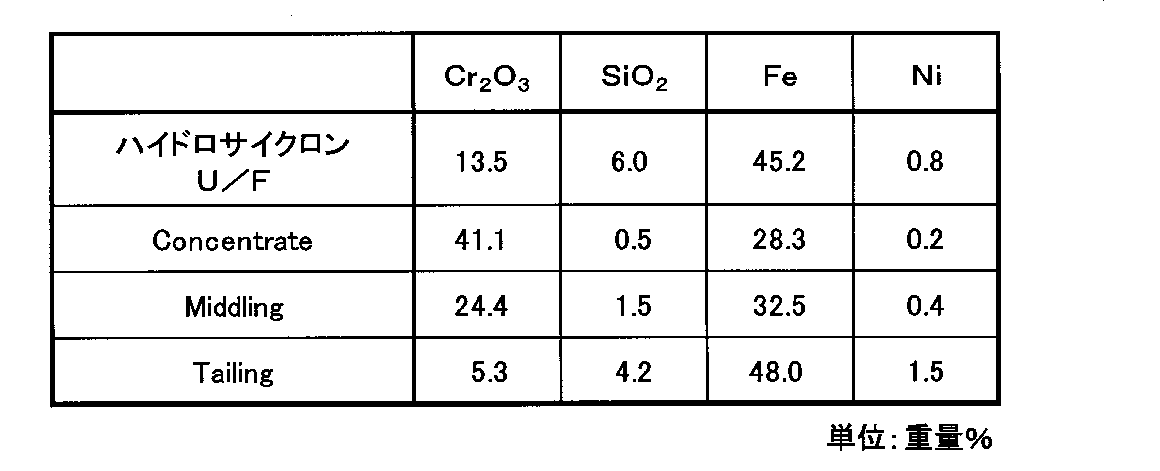
Middlingでは24.4重量%に上昇した。一方、Tailingでは5.3重量%となった。
この結果からスパイラル処理によっても、クロマイトが分離されることが分かる。
試験の結果を表6に記す。
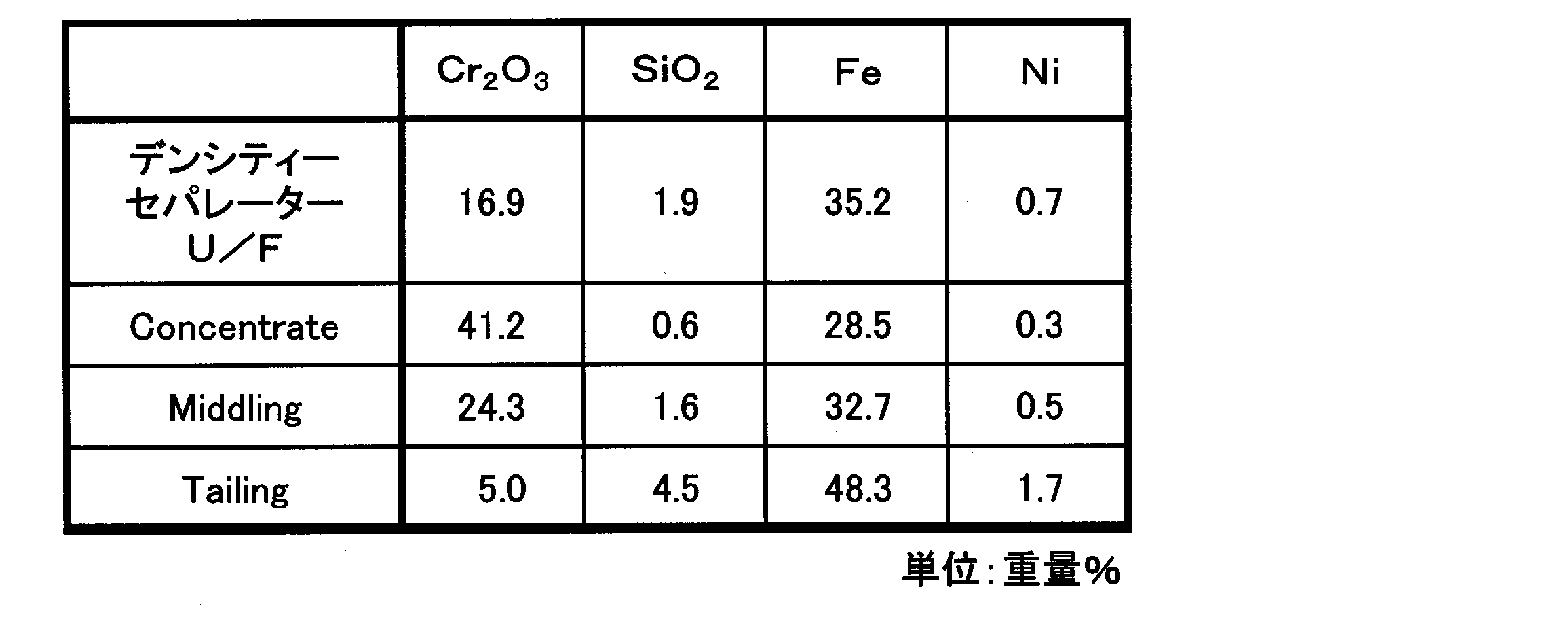
Middlingでは24.3重量%に上昇した。一方、Tailingでは5.0重量%となった。
この結果からスパイラル処理により、クロマイトが分離されることが分かる。
その結果を表7に示す。
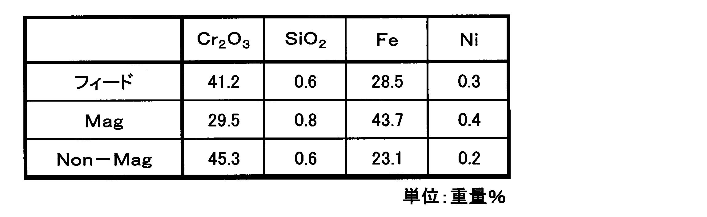
対して、Cr2O3(着磁物/Mag)のFe品位は43.7重量%と、Fe品位が高いことからも、磁力選鉱によりヘマタイトが分離除去され、クロマイトのCr2O3品位が上昇したことがわかる。
また、得られたクロマイトの回収率は42.5重量%であった。
なお、回収率の計算は下記の式(6)で求めた。

低磁界磁力選鉱で得られたNon-Magスラリーを、53μmと300μmのメッシュを備えた分級装置(株式会社DALTON製:振動ふるい機702CB)で分級処理を行った。
その結果を表8に示す。
表8から分級処理により得られるCr2O3は給鉱中の45.3重量%に対し51.4重量%に上昇した。
以上の結果から、実施例1で示される本発明の製錬方法では、一般に市販されるクロマイトのCr2O3品位を上回る濃度まで濃縮が可能であると言える。
実施例1で得られたクロマイトの回収率は19%であった。なお、回収率の計算は式(6)で求めた。
実施例2では、スラリー濃度は15重量%、スラリーの温度を常温とし、運転圧力を0.2MPaの条件で分級を行った。
鉱石スラリー組成と、ハイドロサイクロンU/Fの組成を、表9に併せて記す。なお、以下の表の単位は重量%とした。

以上より、鉱石スラリーの分級により、粗粒部にシリカ鉱物、クロマイトが濃縮され、分離されていることが分かる。
その供給速度を56[kg/Hr]、スラリーの温度を常温とした。
この時のTeeter Water量は、6.9[m3・h-1/m2]、Set Point(密度計の設定値)を20として行った。
デンシティ セパレーター(1)のフィード(ハイドロサイクロンU/F)およびアンダーフロー(デンシティ セパレーターU/F(1))の組成を表10に記す。
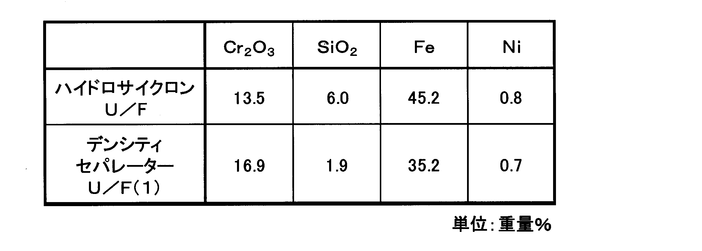
以上より、デンシティ セパレーター処理により、粗粒部にクロマイトが濃縮され、分離されることが分かる。

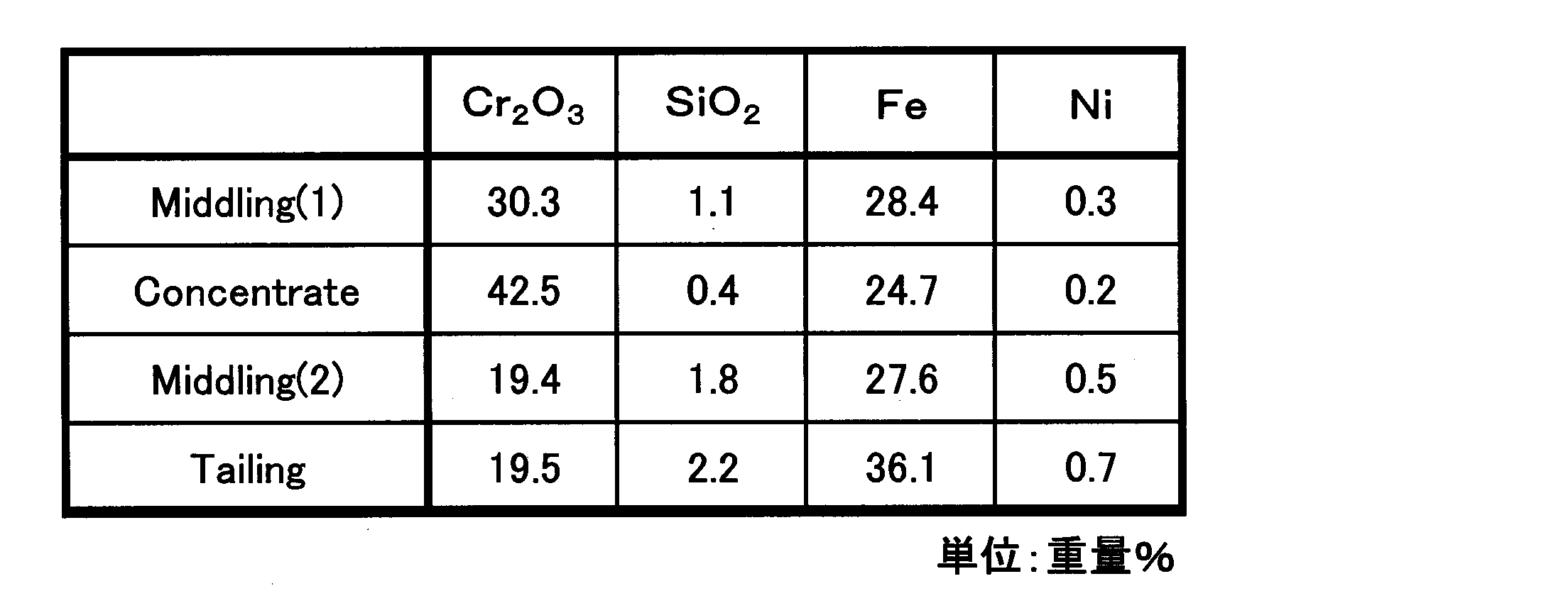
スパイラル試験の結果を表12に記す。

この結果からスパイラル処理により、クロマイトが分離されることが分かる。

対して、Cr2O3(着磁物/Mag)のFe品位は36.6重量%と、Fe品位が高いことからも、磁力選鉱によりマグネタイトが分離除去され、クロマイトのCr2O3品位が上昇したことがわかる。
また、得られたクロマイトの回収率は44%であった。
回収率の計算は実施例1と同様に式(6)で求めた。
その低磁界磁力選鉱で得られたNon-Magスラリーを、53μmと300μmのメッシュを備えた分級装置(株式会社DALTON製:振動ふるい機702CB)で分級処理を行った。
表15から分級処理により得られるCr2O3は給鉱中の48.5重量%に対し55.0重量%に上昇した。一方Feは20.0重量%から27.0重量%に上昇した。
実施例2で得られたクロマイトの回収率は20%であった。なお、回収率の計算は実施例1と同様に式(6)で求めた。
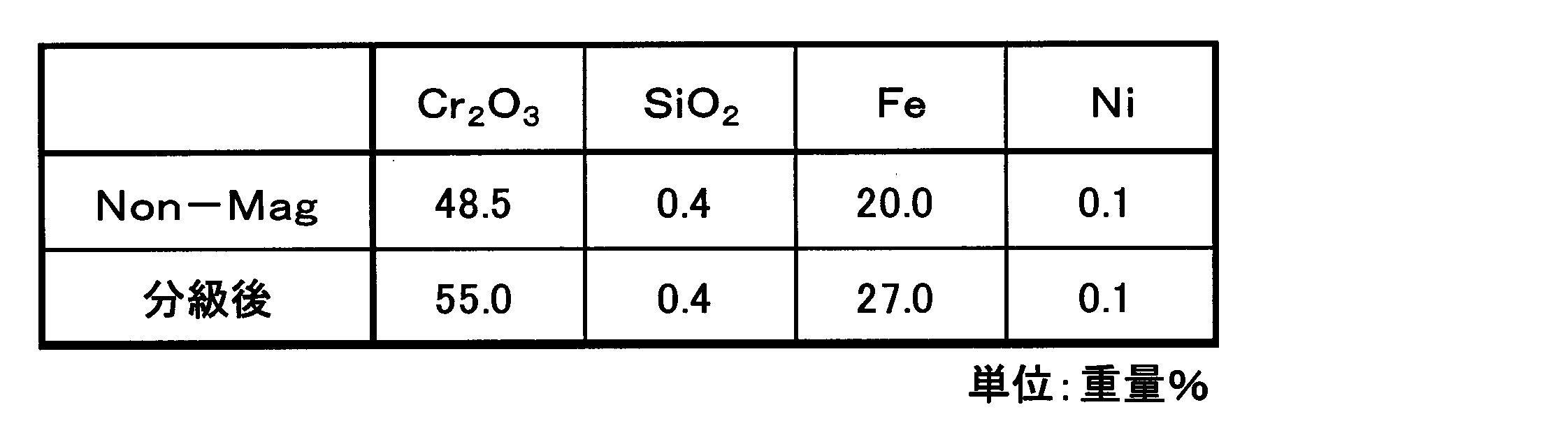
図5に示す比較例1における実施フローに沿って、ハイドロサイクロンによる分級処理後、実施例1の比重分離処理に代り、ハイメッシュセパレーターを用いた鉱石スラリー中に含まれる固形物の大きさによる分離を行った。
分級装置として、ハイドロサイクロン(アタカ大樹株式会社製、「MD-9型」)を用いて、鉱石スラリーの分級を行った。
ここで、スラリー濃度を9.8重量%、スラリーの温度は常温とし、運転圧力0.22MPaの条件で分級を行った。
ハイメッシュセパレーターへの供給速度は0.98[m3/時]、バケットの回転数は0.8rpm、バケット長は75mm、バケットは4mm直径の孔が6mmピッチで開いており、開孔率は40%である。
洗浄水量は6m3/時とした。
鉱石スラリーとハイドロサイクロンのアンダーフロー(ハイドロサイクロンU/F)の組成、及びハイメッシュセパレーターのアンダーフロー(ハイメッシュセパレーターU/F)の組成を表16に記す。
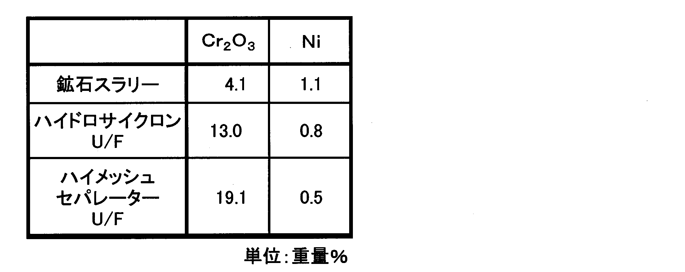
この工程の中では、特にハイドロサイクロンによる濃縮には問題は見られなかったが、ハイメッシュセパレーターでの濃縮が不十分であると判定できる。
それぞれのアンダーフロー(ハイドロサイクロン-U/F、ハイメッシュセパレーター-U/F)を75μmで篩い、その上下の分析を実施したところ、表17に示す結果が得られた。

この結果から、ハイメッシュセパレーターはスライム除去の仕事しかしておらず、比重分離の仕事をしていない。
このように市販レベルのCr2O3品位を持つクロマイトは、比重分離を行わない限り、濃縮できないことがわかる。
さらに、作製した浸出スラリーを固液分離工程により浸出液11と浸出残渣スラリー12に分離した。
浸出温度:245℃
浸出時間:60分
最終(浸出終了時の)遊離硫酸濃度:40[g/L]
スラリー濃度:30重量%
オートクレーブ容量:5L
次に、このスラリーを5C濾紙で固液分離し、さらにMg(OH)2スラリーをpH6になるまで添加した後、さらに5C濾紙で固液分離した。
実施例1の鉱石スラリーをハイドロサイクロンと、デンシティ セパレーターで処理することなくオートクレーブに装入し、それ以外は実施例3と同様に処理したところ、得られた最終中和残渣のCr2O3品位は2.1重量%であった。
生成するMgSO4の溶解度が大きいため、残渣のイオウ品位は0.53重量%であった。
実施例3と同様にして浸出残渣スラリー12を作製し、その全量に濃度25重量%の消石灰スラリーを中和剤として添加し、60℃で、pH8.5になるように中和して、金属イオンを澱物として沈殿させ、固液分離により中和残渣と中和後処理液を得た。
ヘマタイト28を分離した残りの中和残渣と中和後処理液を混合した混合液に、濃度25重量%の消石灰スラリーを添加した後、5C濾紙での固液分離を繰り返して最終中和残渣を得た。
図6の比較例4の実施フロー図に示されるように、ハイドロサイクロンによる分級処理をせずに、鉱石スラリーを実施例1と同様に比重分離を1処理し、最後にハイドロサイクロンによる分級処理を実施した以外は、実施例1と同じ条件で分離試験を行った。
表18は、ハイドロサイクロンによる分級処理を行わなかった鉱石を、デンシティ セパレーターで比重分離処理した結果である。

表19から明らかなように、スパイラルセパレーターによる比重分離処理を行っても、Cr2O3濃度は25.3重量%と41重量%以上にはならなかった。
このことは、デンシティ セパレーターで粗粒と細粒の分離が出来ていないため、スラリー粘度が高く、スパイラルの効果が発揮できないと考えられる。

表20に示した通り、Cr2O3濃度は35.3重量%と41重量%以上を満たすことはなかった。
9 鉱石スラリー
10 浸出スラリー
11 浸出液
12 浸出残渣スラリー
14 母液(1)
15 硫化亜鉛澱物
16 母液(2)
17 Ni,Co混合硫化物
18 貧液
19 最終中和残渣
20 テーリングダム
22 オートクレーブ供給スラリー
23 クロマイト
26 (B-1)工程残渣
27 (B-2)工程後処理液
28 ヘマタイト
Claims (19)
- 鉱石処理工程、浸出工程、固液分離工程、中和工程、亜鉛除去工程、硫化工程及び最終中和工程を含む高圧酸浸出法を用いて、ニッケル及びコバルトを回収するニッケル酸化鉱石の湿式製錬方法において、下記(A)工程を含むことを特徴とするニッケル酸化鉱石の湿式製錬方法。
記
(A)工程:前記鉱石処理工程から産出する鉱石スラリー中のクロマイト粒子を、比重分離法を含む回収プロセスにより分離した後、分級処理を行い、高濃度クロマイト濃縮物を回収する工程。 - 鉱石処理工程、浸出工程、固液分離工程、中和工程、亜鉛除去工程、硫化工程及び最終中和工程を含む高圧酸浸出法を用いて、ニッケル及びコバルトを回収するニッケル酸化鉱石の湿式製錬方法において、下記(A)工程を含み、且つ前記(A)工程を経た後に、(B-1)工程、(B-2)工程のいずれかを含むことを特徴とするニッケル酸化鉱石の湿式製錬方法。
記
(A)工程:前記鉱石処理工程から産出する鉱石スラリー中のクロマイト粒子を、比重分離法を含む回収プロセスにより分離した後、分級処理を行い、高濃度クロマイト濃縮物を回収する工程。
(B-1)工程:前記(A)工程を経てクロマイト粒子を分離してCr品位の下がった鉱石スラリーを、前記浸出工程、固液分離工程の順に処理して生成した浸出液を中和処理する中和工程であって、
前記中和処理に際してCa系又はMg系中和剤の少なくとも一種以上を用いて中和する工程。
(B-2)工程:前記(A)工程を経てクロマイト粒子を分離してCr品位の下がった鉱石スラリーを、前記浸出工程、固液分離工程の順に処理して生成した浸出残渣スラリーを中和処理する中和工程であって、
前記中和処理に際してMg系中和剤を用いて中和処理し、前記浸出残渣スラリーからヘマタイト粒子を回収する工程。 - 鉱石処理工程、浸出工程、固液分離工程、中和工程、亜鉛除去工程、硫化工程及び最終中和工程を含む高圧酸浸出法を用いてニッケル酸化鉱石からニッケル及びコバルトを回収する湿式製錬方法において、
下記(A)工程、(B-1)工程、及び(B-2)工程を含むことを特徴とするニッケル酸化鉱石の湿式製錬方法。
記
(A)工程:前記鉱石処理工程から産出する鉱石スラリー中のクロマイト粒子を、比重分離法を含む回収プロセスにより分離した後、分級処理を行い、高濃度クロマイト濃縮物を回収する工程。
(B-1)工程:前記(A)工程を経てクロマイト粒子を分離してCr品位の下がった鉱石スラリーを、前記浸出工程、固液分離工程の順に処理して生成した浸出液を中和処理する中和工程であって、
前記中和処理に際してCa系又はMg系中和剤の少なくとも一種以上を用いて中和する工程。
(B-2)工程:前記(A)工程を経てクロマイト粒子を分離してCr品位の下がった鉱石スラリーを、前記浸出工程、固液分離工程の順に処理して生成した浸出残渣スラリーを中和処理する中和工程であって、
前記中和処理に際してMg系中和剤を用いて中和処理し、前記浸出残渣スラリーからヘマタイト粒子を回収する工程。 - 前記(A)工程の回収プロセスが、前記鉱石スラリーにサイクロンによる分級処理を行って、微細な鉄水酸化物粒子を低減させた貧鉄粒子鉱石スラリーを形成した後、前記貧鉄粒子鉱石スラリーに含まれるクロマイト粒子を、比重分離法を用いてクロマイト濃縮物として前記鉱石スラリーから回収することを特徴とする請求項1~3のいずれか1項に記載のニッケル酸化鉱石の湿式製錬方法。
- 前記(A)工程の回収プロセスが、前記鉱石スラリーのスラリー濃度を希釈せずに、サイクロンによる分級処理することを特徴とする請求項4に記載のニッケル酸化鉱石の湿式製錬方法。
- 前記(A)工程の回収プロセスが、サイクロンによる分級処理におけるクロマイトのアンダーフローへの採取が不可避的損失を除く全量が行われることを特徴とする請求項1~5のいずれか1項に記載のニッケル酸化鉱石の湿式製錬方法。
- 前記比重分離法が、デンシティ セパレーターを用いる工程を含むことを特徴とする請求項1~6のいずれか1項に記載のニッケル酸化鉱石の湿式製錬方法。
- 前記比重分離法が、スパイラルコンセントレーターを用いる工程を含むことを特徴とする請求項1~6のいずれか1項に記載のニッケル酸化鉱石の湿式製錬方法。
- 前記比重分離法が、デンシティ セパレーターを用いる工程及びスパイラルコンセントレーターを用いる工程を含むことを特徴とする請求項1~6のいずれか1項に記載のニッケル酸化鉱石の湿式製錬方法。
- 前記デンシティ セパレーターを用いる工程が、濃縮スラリーを二回以上デンシティ セパレーターで処理することを特徴とする請求項7又は9に記載のニッケル酸化鉱石の湿式製錬方法。
- 前記スパイラルコンセントレーターを用いる工程が、濃縮スラリーを二回以上スパイラルコンセントレーターで処理することを特徴とする請求項8又は9に記載のニッケル酸化鉱石の湿式製錬方法。
- 前記スパイラルコンセントレーターに供給されるスラリーのパルプコンテントが、15~35重量%Solidであることを特徴とする請求項8、9、11のいずれか1項に記載のニッケル酸化鉱石の湿式製錬方法。
- 前記デンシティ セパレーターに供給されるTeeter Water量が、0.5~7.0[m3・h-1/m2]であることを特徴とする請求項7、9、10のいずれか1項に記載のニッケル酸化鉱石の湿式製錬方法。
- 前記比重分離法により分離されたクロマイト濃縮物に、物理分離処理である磁力分離法を施して前記クロマイト濃縮物中のマグネタイトを着磁物として除去し、非着磁物を高濃度クロマイト濃縮物として回収することを特徴とする請求項1~13のいずれか1つに記載のニッケル酸化鉱石の湿式製錬方法。
- 前記(B-2)工程が、中和処理後のpHを4~7とし、前記中和処理後にMg系中和剤以外のアルカリで最終中和を行うことを特徴とする請求項2又は3に記載のニッケル酸化鉱石の湿式製錬方法。
- 前記(B-2)工程が、前記浸出残渣スラリー又は前記浸出残渣スラリーを含む中和残渣スラリーに、サイクロンによる分級処理を施し、前記分級処理により得られた分級された細粒部を、ヘマタイトの濃縮物として回収することを特徴とする請求項2又は3に記載のニッケル酸化鉱石の湿式製錬方法。
- 前記鉱石処理工程は、採掘した原料鉱石の異物除去及び鉱石粒度調整を行い、鉱石スラリーを形成する工程、
前記浸出工程は、前記鉱石スラリーに硫酸を添加し、高温高圧下で撹拌処理して、浸出残渣と浸出液からなる浸出スラリーを形成する工程、
前記固液分離工程は、前記浸出スラリーを多段洗浄して、ニッケル及びコバルトを含む浸出液と浸出残渣スラリーを得る工程、
前記中和工程は、前記浸出液にアルカリを添加し、3価の鉄を含む中和澱物スラリーとニッケル回収用の母液を形成する工程、
前記亜鉛除去工程は、前記母液に硫化水素ガスを吹きこみ、硫化亜鉛澱物スラリーとニッケル及びコバルト回収用の母液を形成する工程、
前記硫化工程は、前記ニッケル及びコバルト回収用の母液に、硫化水素を吹き込み、ニッケル及びコバルトを含む混合硫化物と貧液とを生成する工程、
及び最終中和工程は、前記浸出残渣スラリーに余剰の前記貧液を加え、pHを8~9に調整し、最終中和残渣を得る工程であることを特徴とする請求項1~16のいずれか1項に記載のニッケル酸化鉱石の湿式製錬方法。 - 前記鉱石処理工程における鉱石粒度調整が、2mm以下の粒度で篩い分け処理による粒度調整であることを特徴とする請求項1~17のいずれか1項に記載のニッケル酸化鉱石の湿式製錬方法。
- 濃縮されたクロマイトのCr2O3品位が、41重量%以上であることを特徴とする請求項1~18のいずれか1項に記載のニッケル酸化鉱石の湿式製錬方法。
Priority Applications (7)
| Application Number | Priority Date | Filing Date | Title |
|---|---|---|---|
| CA2946106A CA2946106C (en) | 2014-04-18 | 2015-03-27 | Hydrometallurgical method for nickel oxide ore |
| EP15780623.3A EP3133177B1 (en) | 2014-04-18 | 2015-03-27 | Wet-mode nickel oxide ore smelting method |
| AU2015247229A AU2015247229B2 (en) | 2014-04-18 | 2015-03-27 | Wet-mode nickel oxide ore smelting method |
| US15/304,898 US20170175227A1 (en) | 2014-04-18 | 2015-03-27 | Hydrometallurgical process for nickel oxide ore |
| CN201580020168.1A CN106232842A (zh) | 2014-04-18 | 2015-03-27 | 镍氧化矿石的湿式冶炼方法 |
| PH12016502070A PH12016502070A1 (en) | 2014-04-18 | 2016-10-18 | Hydrometallurgical process for nickel oxide ore |
| US16/554,982 US20190382870A1 (en) | 2014-04-18 | 2019-08-29 | Hydrometallurgical process for nickel oxide ore |
Applications Claiming Priority (2)
| Application Number | Priority Date | Filing Date | Title |
|---|---|---|---|
| JP2014086590A JP6183788B2 (ja) | 2014-04-18 | 2014-04-18 | ニッケル酸化鉱石の湿式製錬方法 |
| JP2014-086590 | 2014-04-18 |
Related Child Applications (2)
| Application Number | Title | Priority Date | Filing Date |
|---|---|---|---|
| US15/304,898 A-371-Of-International US20170175227A1 (en) | 2014-04-18 | 2015-03-27 | Hydrometallurgical process for nickel oxide ore |
| US16/554,982 Division US20190382870A1 (en) | 2014-04-18 | 2019-08-29 | Hydrometallurgical process for nickel oxide ore |
Publications (1)
| Publication Number | Publication Date |
|---|---|
| WO2015159685A1 true WO2015159685A1 (ja) | 2015-10-22 |
Family
ID=54323896
Family Applications (1)
| Application Number | Title | Priority Date | Filing Date |
|---|---|---|---|
| PCT/JP2015/059674 Ceased WO2015159685A1 (ja) | 2014-04-18 | 2015-03-27 | ニッケル酸化鉱石の湿式製錬方法 |
Country Status (8)
| Country | Link |
|---|---|
| US (2) | US20170175227A1 (ja) |
| EP (1) | EP3133177B1 (ja) |
| JP (1) | JP6183788B2 (ja) |
| CN (1) | CN106232842A (ja) |
| AU (1) | AU2015247229B2 (ja) |
| CA (1) | CA2946106C (ja) |
| PH (1) | PH12016502070A1 (ja) |
| WO (1) | WO2015159685A1 (ja) |
Cited By (1)
| Publication number | Priority date | Publication date | Assignee | Title |
|---|---|---|---|---|
| JP7151848B1 (ja) | 2021-09-15 | 2022-10-12 | 住友金属鉱山株式会社 | クロム鉄鉱石の回収方法 |
Families Citing this family (13)
| Publication number | Priority date | Publication date | Assignee | Title |
|---|---|---|---|---|
| JP6202083B2 (ja) * | 2015-12-25 | 2017-09-27 | 住友金属鉱山株式会社 | 硫化剤の除去方法 |
| CN105567964B (zh) * | 2015-12-28 | 2017-05-17 | 中南大学 | 一种含钒铬溶液选择性还原分离回收钒和铬的方法 |
| JP7087601B2 (ja) * | 2018-04-06 | 2022-06-21 | 住友金属鉱山株式会社 | 硫化剤の除去方法及びニッケル酸化鉱石の湿式製錬方法 |
| CN112080636B (zh) * | 2020-08-17 | 2022-11-15 | 广东邦普循环科技有限公司 | 一种利用红土镍矿生产电池级硫酸镍盐的方法 |
| JP7687079B2 (ja) * | 2021-06-23 | 2025-06-03 | 住友金属鉱山株式会社 | 含クロマイトスラリーの分配装置及びこれを用いたクロマイトの回収方法 |
| JP2023042898A (ja) * | 2021-09-15 | 2023-03-28 | 住友金属鉱山株式会社 | クロム鉄鉱石の回収方法 |
| JP2023050767A (ja) * | 2021-09-30 | 2023-04-11 | 住友金属鉱山株式会社 | クロム鉄鉱石の回収方法 |
| JP7848511B2 (ja) * | 2022-02-25 | 2026-04-21 | 住友金属鉱山株式会社 | クロム鉄鉱石の分離回収設備、及び、クロム鉄鉱石の回収方法 |
| JP7658359B2 (ja) * | 2022-12-29 | 2025-04-08 | 住友金属鉱山株式会社 | ニッケル酸化鉱石の高圧硫酸浸出における制御方法 |
| CN116790875B (zh) * | 2023-06-15 | 2025-02-18 | 四川顺应动力电池材料有限公司 | 一种红土镍矿脱硫的方法 |
| AU2023446739B2 (en) * | 2023-07-27 | 2025-07-10 | Gem Co., Ltd. | Method for extracting nickel-cobalt-manganese from laterite nickel ore by acid leaching |
| WO2026049200A1 (ko) * | 2024-08-30 | 2026-03-05 | 고려아연 주식회사 | 황화물 형태의 니켈 매트로부터의 니켈 회수 방법 |
| WO2026049131A1 (ko) * | 2024-08-30 | 2026-03-05 | 고려아연 주식회사 | 황화물 형태의 니켈 매트로부터의 니켈 회수 방법 |
Citations (4)
| Publication number | Priority date | Publication date | Assignee | Title |
|---|---|---|---|---|
| JP2010100915A (ja) * | 2008-10-27 | 2010-05-06 | Jfe Steel Corp | 竪型炉の操業方法 |
| JP2013095971A (ja) * | 2011-11-01 | 2013-05-20 | Sumitomo Metal Mining Co Ltd | ニッケル酸化鉱石の湿式製錬方法 |
| WO2014125558A1 (ja) * | 2013-02-12 | 2014-08-21 | 住友金属鉱山株式会社 | ニッケル酸化鉱石の湿式製錬方法 |
| WO2014175093A1 (ja) * | 2013-04-23 | 2014-10-30 | 住友金属鉱山株式会社 | ニッケル酸化鉱石の湿式製錬方法 |
Family Cites Families (5)
| Publication number | Priority date | Publication date | Assignee | Title |
|---|---|---|---|---|
| US3961908A (en) * | 1974-02-27 | 1976-06-08 | Freeport Minerals Company | Autoclave system for leaching sulfide concentrates |
| CN101638730B (zh) * | 2008-07-31 | 2015-03-25 | 塔塔钢铁有限公司 | 用于从冶金级铬铁矿精矿细粉生产海绵铬的方法 |
| JP5446226B2 (ja) * | 2008-09-19 | 2014-03-19 | 住友金属鉱山株式会社 | ニッケル酸化鉱石の湿式製錬方法 |
| AU2009212947B2 (en) * | 2008-09-19 | 2014-06-05 | Sumitomo Metal Mining Co., Ltd. | Hydrometallurgical process of nickel laterite ore |
| JP5556608B2 (ja) * | 2010-11-17 | 2014-07-23 | 住友金属鉱山株式会社 | クロマイト回収方法、並びにニッケル酸化鉱石の湿式製錬方法 |
-
2014
- 2014-04-18 JP JP2014086590A patent/JP6183788B2/ja active Active
-
2015
- 2015-03-27 US US15/304,898 patent/US20170175227A1/en not_active Abandoned
- 2015-03-27 CN CN201580020168.1A patent/CN106232842A/zh active Pending
- 2015-03-27 EP EP15780623.3A patent/EP3133177B1/en not_active Not-in-force
- 2015-03-27 WO PCT/JP2015/059674 patent/WO2015159685A1/ja not_active Ceased
- 2015-03-27 CA CA2946106A patent/CA2946106C/en not_active Expired - Fee Related
- 2015-03-27 AU AU2015247229A patent/AU2015247229B2/en not_active Ceased
-
2016
- 2016-10-18 PH PH12016502070A patent/PH12016502070A1/en unknown
-
2019
- 2019-08-29 US US16/554,982 patent/US20190382870A1/en not_active Abandoned
Patent Citations (4)
| Publication number | Priority date | Publication date | Assignee | Title |
|---|---|---|---|---|
| JP2010100915A (ja) * | 2008-10-27 | 2010-05-06 | Jfe Steel Corp | 竪型炉の操業方法 |
| JP2013095971A (ja) * | 2011-11-01 | 2013-05-20 | Sumitomo Metal Mining Co Ltd | ニッケル酸化鉱石の湿式製錬方法 |
| WO2014125558A1 (ja) * | 2013-02-12 | 2014-08-21 | 住友金属鉱山株式会社 | ニッケル酸化鉱石の湿式製錬方法 |
| WO2014175093A1 (ja) * | 2013-04-23 | 2014-10-30 | 住友金属鉱山株式会社 | ニッケル酸化鉱石の湿式製錬方法 |
Non-Patent Citations (1)
| Title |
|---|
| See also references of EP3133177A4 * |
Cited By (2)
| Publication number | Priority date | Publication date | Assignee | Title |
|---|---|---|---|---|
| JP7151848B1 (ja) | 2021-09-15 | 2022-10-12 | 住友金属鉱山株式会社 | クロム鉄鉱石の回収方法 |
| JP2023042931A (ja) * | 2021-09-15 | 2023-03-28 | 住友金属鉱山株式会社 | クロム鉄鉱石の回収方法 |
Also Published As
| Publication number | Publication date |
|---|---|
| EP3133177A1 (en) | 2017-02-22 |
| US20170175227A1 (en) | 2017-06-22 |
| PH12016502070A1 (en) | 2016-12-19 |
| EP3133177A4 (en) | 2017-12-27 |
| CN106232842A (zh) | 2016-12-14 |
| AU2015247229A1 (en) | 2016-11-10 |
| JP6183788B2 (ja) | 2017-08-23 |
| JP2015206068A (ja) | 2015-11-19 |
| US20190382870A1 (en) | 2019-12-19 |
| EP3133177B1 (en) | 2020-09-02 |
| CA2946106C (en) | 2019-08-20 |
| AU2015247229B2 (en) | 2019-05-02 |
| CA2946106A1 (en) | 2015-10-22 |
Similar Documents
| Publication | Publication Date | Title |
|---|---|---|
| JP5867768B2 (ja) | ニッケル酸化鉱石の湿式製錬におけるニッケル酸化鉱石からのクロマイト粒子回収方法及びニッケル酸化鉱石の湿式製錬設備 | |
| JP6183788B2 (ja) | ニッケル酸化鉱石の湿式製錬方法 | |
| JP5446226B2 (ja) | ニッケル酸化鉱石の湿式製錬方法 | |
| JP5403033B2 (ja) | ニッケル酸化鉱石の湿式製錬方法 | |
| JP2015206068A5 (ja) | ||
| JP2013095971A5 (ja) | ||
| US9783869B2 (en) | Hydrometallurgical process for nickel oxide ore | |
| JP5556608B2 (ja) | クロマイト回収方法、並びにニッケル酸化鉱石の湿式製錬方法 | |
| JP6661926B2 (ja) | 鉱石スラリーの処理方法、ニッケル酸化鉱石の湿式製錬方法 | |
| JP6565511B2 (ja) | 鉱石スラリーの処理方法、ニッケル酸化鉱石の湿式製錬方法 | |
| CA2977602C (en) | Ore slurry pre-treatment method and ore slurry manufacturing method | |
| JP6969262B2 (ja) | ニッケル酸化鉱石の湿式製錬方法 | |
| CA2984885A1 (en) | Mineral ore slurry pretreatment method, and method for manufacturing mineral ore slurry | |
| JP5790839B2 (ja) | クロマイト回収方法 | |
| JP6977458B2 (ja) | ニッケル酸化鉱石の湿式製錬方法 |
Legal Events
| Date | Code | Title | Description |
|---|---|---|---|
| 121 | Ep: the epo has been informed by wipo that ep was designated in this application |
Ref document number: 15780623 Country of ref document: EP Kind code of ref document: A1 |
|
| WWE | Wipo information: entry into national phase |
Ref document number: 12016502070 Country of ref document: PH |
|
| ENP | Entry into the national phase |
Ref document number: 2946106 Country of ref document: CA |
|
| NENP | Non-entry into the national phase |
Ref country code: DE |
|
| WWE | Wipo information: entry into national phase |
Ref document number: 15304898 Country of ref document: US |
|
| ENP | Entry into the national phase |
Ref document number: 2015247229 Country of ref document: AU Date of ref document: 20150327 Kind code of ref document: A |
|
| REEP | Request for entry into the european phase |
Ref document number: 2015780623 Country of ref document: EP |
|
| WWE | Wipo information: entry into national phase |
Ref document number: 2015780623 Country of ref document: EP |