WO2015159763A1 - 異物除去装置 - Google Patents
異物除去装置 Download PDFInfo
- Publication number
- WO2015159763A1 WO2015159763A1 PCT/JP2015/060877 JP2015060877W WO2015159763A1 WO 2015159763 A1 WO2015159763 A1 WO 2015159763A1 JP 2015060877 W JP2015060877 W JP 2015060877W WO 2015159763 A1 WO2015159763 A1 WO 2015159763A1
- Authority
- WO
- WIPO (PCT)
- Prior art keywords
- piston
- rack
- space
- foreign matter
- matter removing
- Prior art date
- Legal status (The legal status is an assumption and is not a legal conclusion. Google has not performed a legal analysis and makes no representation as to the accuracy of the status listed.)
- Ceased
Links
Images










Classifications
-
- B—PERFORMING OPERATIONS; TRANSPORTING
- B60—VEHICLES IN GENERAL
- B60S—SERVICING, CLEANING, REPAIRING, SUPPORTING, LIFTING, OR MANOEUVRING OF VEHICLES, NOT OTHERWISE PROVIDED FOR
- B60S1/00—Cleaning of vehicles
- B60S1/02—Cleaning windscreens, windows or optical devices
- B60S1/56—Cleaning windscreens, windows or optical devices specially adapted for cleaning other parts or devices than front windows or windscreens
-
- B—PERFORMING OPERATIONS; TRANSPORTING
- B60—VEHICLES IN GENERAL
- B60S—SERVICING, CLEANING, REPAIRING, SUPPORTING, LIFTING, OR MANOEUVRING OF VEHICLES, NOT OTHERWISE PROVIDED FOR
- B60S1/00—Cleaning of vehicles
- B60S1/02—Cleaning windscreens, windows or optical devices
- B60S1/54—Cleaning windscreens, windows or optical devices using gas, e.g. hot air
-
- F—MECHANICAL ENGINEERING; LIGHTING; HEATING; WEAPONS; BLASTING
- F04—POSITIVE - DISPLACEMENT MACHINES FOR LIQUIDS; PUMPS FOR LIQUIDS OR ELASTIC FLUIDS
- F04B—POSITIVE-DISPLACEMENT MACHINES FOR LIQUIDS; PUMPS
- F04B35/00—Piston pumps specially adapted for elastic fluids and characterised by the driving means to their working members, or by combination with, or adaptation to, specific driving engines or motors, not otherwise provided for
- F04B35/01—Piston pumps specially adapted for elastic fluids and characterised by the driving means to their working members, or by combination with, or adaptation to, specific driving engines or motors, not otherwise provided for the means being mechanical
-
- F—MECHANICAL ENGINEERING; LIGHTING; HEATING; WEAPONS; BLASTING
- F04—POSITIVE - DISPLACEMENT MACHINES FOR LIQUIDS; PUMPS FOR LIQUIDS OR ELASTIC FLUIDS
- F04B—POSITIVE-DISPLACEMENT MACHINES FOR LIQUIDS; PUMPS
- F04B39/00—Component parts, details, or accessories, of pumps or pumping systems specially adapted for elastic fluids, not otherwise provided for in, or of interest apart from, groups F04B25/00 - F04B37/00
- F04B39/0005—Component parts, details, or accessories, of pumps or pumping systems specially adapted for elastic fluids, not otherwise provided for in, or of interest apart from, groups F04B25/00 - F04B37/00 adaptations of pistons
-
- F—MECHANICAL ENGINEERING; LIGHTING; HEATING; WEAPONS; BLASTING
- F04—POSITIVE - DISPLACEMENT MACHINES FOR LIQUIDS; PUMPS FOR LIQUIDS OR ELASTIC FLUIDS
- F04B—POSITIVE-DISPLACEMENT MACHINES FOR LIQUIDS; PUMPS
- F04B53/00—Component parts, details or accessories not provided for in, or of interest apart from, groups F04B1/00 - F04B23/00 or F04B39/00 - F04B47/00
- F04B53/008—Spacing or clearance between cylinder and piston
-
- F—MECHANICAL ENGINEERING; LIGHTING; HEATING; WEAPONS; BLASTING
- F04—POSITIVE - DISPLACEMENT MACHINES FOR LIQUIDS; PUMPS FOR LIQUIDS OR ELASTIC FLUIDS
- F04B—POSITIVE-DISPLACEMENT MACHINES FOR LIQUIDS; PUMPS
- F04B9/00—Piston machines or pumps characterised by the driving or driven means to or from their working members
- F04B9/02—Piston machines or pumps characterised by the driving or driven means to or from their working members the means being mechanical
Definitions
- the present invention relates to a technical field of a foreign matter removing apparatus that ejects high pressure air from a nozzle to remove foreign matter.
- a structure such as a vehicle.
- an in-vehicle camera, a vehicle lamp, and a rearview mirror are provided with moisture in order to ensure good visibility. It is desirable to remove foreign matters such as dirt, mud and dust.
- in-vehicle cameras are used as devices that display images on the display to check the back of the vehicle or to check the position outside the vehicle that is difficult for the driver to see.
- the imaging unit may be contaminated by water droplets or the like adhering to the time, and the image projected on the display may become unclear and may hinder the confirmation.
- a liquid storage tank is required compared with the foreign matter removing device that jets high-pressure liquid such as water to eliminate contamination. This is advantageous in that it is not performed and the ejected liquid does not remain in the imaging unit.
- the foreign matter removing apparatus that eliminates contamination of the imaging unit with high-pressure air has the above-described advantages, but requires a mechanism that generates high-pressure air and injects the generated high-pressure air.
- the structure becomes complicated and the manufacturing cost increases. Further, it is necessary to efficiently inject high-pressure air from the nozzle.
- the structure of the compressed air generating unit is not disclosed in the foreign matter removing apparatus described in Patent Document 1, and the structure is simplified and the high-pressure air is efficiently injected from the nozzle. May not be secured.
- an object of the present invention is to overcome the above-described problems, to simplify the structure and to ensure an efficient injection state of high-pressure air from a nozzle.
- a foreign matter removing apparatus includes a cylinder into which air is introduced, a piston that is movably supported by the cylinder and sends out the air that has flowed into the cylinder as high-pressure air in a delivery direction, And a nozzle for injecting high-pressure air sent out by a piston.
- an urging spring for urging the piston in the delivery direction is provided, and a moving force is applied to the piston so that the piston is opposite to the delivery direction.
- a moving mechanism for moving the piston in a direction to a predetermined position is provided, and the piston is moved in a direction opposite to the delivery direction by the moving mechanism to increase a biasing force of the biasing spring, and the piston is moved by the moving mechanism.
- the moving mechanism includes a worm that is rotated by a driving force of a driving motor and a worm wheel that is meshed with the worm and rotated as the worm rotates.
- the driving force of the driving motor is transmitted to the piston via the worm and the worm wheel.
- the rack connected with the said piston is provided, the pinion with which the said rack is meshed
- the reciprocation between the top dead center and the bottom dead center of the piston is performed a plurality of times in one rotation of the pinion.
- the advance angle of the worm is 9 ° or more.
- the gear portion is provided with a plurality of gear teeth
- the rack is provided with a plurality of rack teeth
- the plurality of gear teeth are the first gear teeth.
- the plurality of rack teeth are composed of first rack teeth and second rack teeth
- the first gear teeth are composed of the first rack teeth and the second rack teeth.
- the second gear teeth can be engaged with the first rack teeth and cannot be engaged with the second rack teeth, and the piston can move in the delivery direction. Accordingly, when the rack is moved and the worm wheel is rotated, it is desirable that the second gear teeth and the second rack teeth pass each other.
- variety of the said 2nd gear tooth is made into half or less of the width
- gear is the said 1st gear tooth
- the internal space of the said cylinder has the 1st space and 2nd space which continue in the moving direction of the said piston, and the said 1st space is the said 1st space.
- 2 is located on the delivery direction side of the second space, the diameter of at least a part of the second space is larger than the diameter of the first space, and the piston is moved in the cylinder at least in the first space when moved.
- a seal portion is provided in close contact with the inner peripheral surface of the air, and when the piston is moved to the bottom dead center, the entire seal portion is positioned in the second space and flows into the second space. It is desirable that the fluid flows from the second space toward the first space.
- channel extended in the movement direction of the said piston is formed in the outer peripheral side, and the said air inflow groove
- the piston is moved with respect to the cylinder, high pressure air is sent out from the cylinder, and high pressure air is injected from the nozzle, thereby simplifying the structure and ensuring an efficient injection state of the high pressure air from the nozzle. can do.
- FIG. 2 to 18 show an embodiment of the foreign matter removing apparatus of the present invention, and this figure is a perspective view of the foreign matter removing apparatus.
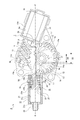
- FIG. 9 and FIG. 10 show the operation of the foreign matter removing apparatus, and this figure is a sectional view showing an initial state.
- the application of the foreign matter removing device of the present invention is not limited to a device that removes foreign matter attached to an in-vehicle camera, and as a device that removes foreign matter attached to various structures, in particular, a vehicle lamp, a window
- the present invention can be widely applied as a foreign matter removing device that removes foreign matter attached to a structure provided in a vehicle such as a mirror and a collision prevention sensor.
- the foreign substance removing device shown below has a cylinder, a piston and a nozzle, and jets high-pressure air from the nozzle by moving the piston relative to the cylinder.
- the direction in which the piston is moved is the front-rear direction and indicates the front-rear, up-down, left-right directions.
- the front and rear, up and down, left and right directions shown below are for convenience of explanation, and the implementation of the present invention is not limited to these directions.
- the foreign matter removing apparatus 1 has a function of removing foreign matters such as moisture, mud and dust attached to the in-vehicle camera 100 for confirming the rear of the vehicle, and is attached to a rear end side portion of the vehicle body (not shown). Yes.
- the foreign matter removing apparatus 1 has a nozzle unit 2, a pipe 3, and a high-pressure air generating unit 4 (see FIG. 1).
- the nozzle unit 2 has a mounting bracket 5 and a nozzle 6.
- the mounting bracket 5 is attached to the rear end of the vehicle body.
- the nozzle 6 has a cylindrical fluid part 6 a extending in the front-rear direction and an injection part 6 b continuous with the rear end of the fluid part 6 a and is formed integrally with the mounting bracket 5.
- the nozzle unit 2 is formed integrally with the in-vehicle camera 100.
- the in-vehicle camera 100 has an imaging unit, and the rear end of the imaging unit is a lens unit 101. Accordingly, the in-vehicle camera 100 captures an image of the subject via the lens unit 101.
- the nozzle 6 is integrally formed with the vehicle-mounted camera 100, the nozzle 6 and the vehicle-mounted camera 100 are assembled to the vehicle body at the same time in one operation. Attaching work can be performed easily and quickly, and workability can be improved.
- the pipe 3 is, for example, a resin or rubber hose, the front end is connected to one end of a later-described cylinder of the high-pressure air generation unit 4, and the rear end is connected to the front end of the flow portion 6 a in the nozzle 6. ing.
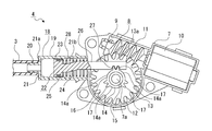
- the high-pressure air generating unit 4 has a case body 7 and a moving mechanism 8 disposed inside the case body 7 (see FIG. 2).
- the high pressure air generating unit 4 is attached to a part of the vehicle body inside the vehicle.
- the inside of the case body 7 is formed as an arrangement space 9, and the arrangement space 9 has a motor arrangement portion 9a, a worm arrangement portion 9b, and a gear arrangement portion 9c.
- the motor placement portion 9a and the worm placement portion 9b are positioned in a state where they are communicated in the front-rear direction, and the worm placement portion 9b and the gear placement portion 9c are located in a state where they are communicated in the vertical direction.
- An insertion hole 9d penetrating in the front-rear direction is formed at the rear end of the case body 7. The insertion hole 9d communicates with the outside of the case body 7 and the gear arrangement portion 9c.
- the case body 7 is provided with a support shaft portion 7a protruding laterally, and the support shaft portion 7a is positioned in the gear arrangement portion 9c.
- the moving mechanism 8 has a drive motor 10, a worm 11, and a worm wheel 12.
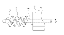
- the drive motor 10 has a main body part 10a and a motor shaft 10b, and the main body part 10a is arranged in the motor arrangement part 9a (see FIGS. 2 and 3).
- the worm 11 is connected and fixed to the motor shaft 10b, and is arranged in the worm arrangement portion 9b.
- the worm 11 has an advance angle of 9 ° or more.
- the thickness of the shaft portion 11a formed in a cylindrical shape is reduced, and the difference between the diameter D1 of the root circle and the diameter D2 of the motor shaft 10b is very small (see FIG. 3).
- the difference between the diameter D1 of the root circle of the worm 11 and the diameter D2 of the motor shaft 10b is made very small, so that the outer diameter of the worm 11 can be reduced, and the worm 11 can be made compact. Can be achieved.
- the worm wheel 12 is formed by integrally forming a driven gear (helical gear) 13 and a pinion 14 projecting laterally from the center of the driven gear 13 (see FIGS. 2 and 4).
- the worm wheel 12 is arranged in the gear arrangement part 9 c, and the center part is supported on the support shaft part 7 a of the case body 7 via the bearing 15.
- the driven gear 13 is meshed with the worm 11.
- the worm 11 has an advance angle of 9 ° or more. Therefore, the irreversibility of the worm 11 is eliminated, and the worm 11 can be rotated with the rotation of the driven gear 13 when the driven gear 13 is rotated in any direction.
- the pinion 14 is coaxial with the driven gear 13 and has an annular portion 16 that is externally fitted to the bearing 15 and gear portions 17, 17, 17 provided on the outer peripheral side of the annular portion 16.
- the gear portions 17, 17, and 17 are provided at regular intervals in the circumferential direction.
- the gear portion 17 is configured by a plurality of, for example, two gear teeth 17a and 17a. However, the number of gear teeth 17a of the gear portion 17 is arbitrary, and may be one or three or more.
- the diameter of the tip circle of the pinion 14 is smaller than the diameter of the root circle of the driven gear 13. Accordingly, the driven gear 13 is formed with a side surface 13a located on the outer peripheral side of the pinion 14 on the side where the pinion 14 is located.
- the portions between the gear portions 17, 17, and 17 are formed as missing tooth portions 14a, 14a, and 14a that are not provided with gear teeth 17a, respectively. For example, three missing teeth 14a are formed at regular intervals in the circumferential direction.
- the worm wheel 12 is formed by integrally forming the driven gear 13 and the pinion 14. Accordingly, the number of parts can be reduced, and the driving force transmitted from the drive motor 10 to the driven gear 13 can be efficiently transmitted to the pinion 14 and the drive motor 10 can be reduced in size. .
- the driven gear 13 and the pinion 14 are coaxial, the driving force transmitted from the driving motor 10 to the driven gear 13 can be transmitted to the pinion 14 more efficiently. Miniaturization can be achieved.
- the thickness of the annular portion 16 in the pinion 14 is reduced, and the difference between the diameter D3 of the root circle and the diameter D4 of the bearing 15 is very small (see FIG. 2).
- a cylinder 18 is coupled to the rear end of the case body 7.
- the cylinder 18 is coupled so as to protrude rearward from the case body 7.
- the cylinder 18 is formed by integrally forming a piston support portion 19 and a connection protrusion 20 protruding rearward from the piston support portion 19, and the diameter of the piston support portion 19 is larger than the diameter of the connection protrusion 20.
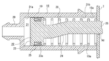
- a substantially half portion on the rear side is a first space 21a and a substantially half portion on the front side is a second space 21b (see FIGS. 5 and 6).
- air inflow grooves 19a and 19a extending in the front-rear direction are formed in the second space 21b so as to be spaced apart in the circumferential direction (see FIGS. 5 to 7).
- the air inflow grooves 19a and 19a are located on the opposite side, for example, 180 °.
- the number of air inflow grooves 19a is arbitrary, and when a plurality of air inflow grooves 19a are formed, it is desirable that they be formed at equal intervals in the circumferential direction.
- the diameter of the portion where the air inflow grooves 19a and 19a are formed in the second space 21b is larger than the diameter of the first space 21a. ⁇ It has been enlarged. The diameter of the portion where the air inflow grooves 19a, 19a are not formed in the second space 21b is the same as the diameter of the first space 21a.
- step surfaces 21c and 21c are formed at the boundary between the first space 21a and the air inflow grooves 19a and 19a, respectively (see FIG. 6).
- An air inflow hole (not shown) is formed in the piston support portion 19 so that outside air flows into the air inflow grooves 19a and 19a from the air inflow hole.
- the central axis of the connecting protrusion 20 coincides with the central axis of the piston support part 19, and the front end of the pipe 3 is connected to the connecting protrusion 20.
- the piston 22 is movably supported on the piston support part 19 of the cylinder 10.
- the piston 22 has an operating part 23 formed in a substantially cylindrical shape with thin front and rear, and a connecting part 24 protruding obliquely upward and forward from the central part of the operating part 23, and the operating part 23 opens outward.
- An annular arrangement groove 23a is formed.
- the outer diameter of the operating portion 23 is slightly smaller than the diameter of the first space 21 a in the piston support portion 19. Accordingly, a gap 21d is formed between the outer peripheral surface of the operating portion 23 and the inner peripheral surface of the piston support portion 19 in the first space 21a.
- the seal portion 25 is arranged in the arrangement groove 23a.
- the seal portion 25 is formed of, for example, rubber or resin that can be elastically deformed, and the outer peripheral portion projects outward from the outer peripheral surface of the operating portion 23.
- the piston 22 is reciprocated in the front-rear direction between the top dead center and the bottom dead center with respect to the cylinder 18.
- the entire operating portion 23 is positioned in the first space 21a (see FIG. 5)
- the entire seal portion 25 is positioned in the second space 21b and the rear end of the operating portion 23 is located.
- the part is located in the first space 21a (see FIG. 6).
- the seal portion 25 is slid on the inner peripheral surface of the cylinder 18 in the first space 21a (see FIG. 5), and the seal portion 25 is other than the air inflow grooves 19a and 19a of the cylinder 18 in the second space 21b.
- This part is separated from the inner peripheral surface of the piston support part 19 in the cylinder 18 at a part where the air inflow grooves 19a, 19a are formed by sliding on the inner peripheral surface of the part (see FIG. 6). Therefore, in a state where the piston 22 is located at the bottom dead center, the air (outside air) flowing into the second space 21b flows along the steps 21c and 21c through the gap 21d toward the first space 21a. Is done.
- a rack 26 extending in the front-rear direction is connected to the connecting portion 24 of the piston 22.
- the rack 26 is formed integrally with the piston 22, for example.
- piston 22 and the rack 26 are integrally formed, it is not necessary to form the piston 22 and the rack 26 separately, and the number of parts can be reduced.
- the rack 26 is formed with a rack portion 27 at a position near the front end.
- the rack portion 27 is constituted by, for example, three rack teeth 27a, 27a, 27a.
- the number of rack teeth 27a of the rack portion 27 is arbitrary, and may be two or less or four or more.
- the rack 26 is inserted through an insertion hole 9 d formed in the case body 7, and the rack portion 27 can be engaged with the gear portion 17 of the pinion 14 in the worm wheel 12.
- the meshing reference line P of the rack portion 27 is substantially coincident with the central axis M of the piston 22.
- the meshing reference line P of the rack 26 and the central axis M of the piston 22 are substantially coincided with each other, so that the moving direction of the piston 22 and the moving direction of the rack 26 are substantially the same.
- the drive motor 10 can be downsized by reducing the load.
- a biasing spring 28 is supported inside the piston support portion 19 of the cylinder 18 between the operating portion 23 of the piston 22 and the outer surface of the case body 7.
- the biasing spring 28 is, for example, a compression coil spring, and the piston 22 and the rack 26 are biased rearward by the biasing spring 28.
- the piston 22 and the rack 26 are urged in the delivery direction by an urging spring 28.
- the piston 22 and the rack 26 are urged in the delivery direction.
- the piston 22 is positioned at the top dead center, and the rack 26 is positioned at the missing tooth portion 14a without the rack portion 27 meshing with the gear portions 17, 17, 17 of the pinion 14.
- the piston 22 moved to the bottom dead center is released at a higher speed than the moving speed in the direction opposite to the sending direction by the biasing force of the biasing spring 28.
- the air that has been moved and has flowed from the second space 21 b to the first space 21 a is sent from the piston support portion 19 to the nozzle 6 of the nozzle unit 2 through the connecting projection 20.
- the diameter of the connecting projection 20 of the cylinder 18 is smaller than the diameter of the piston support 19, the air sent from the piston support 19 through the connection projection 20 is compressed into high-pressure air. Then, it is sent out from the pipe 3 toward the nozzle 6, and high-pressure air is jetted from the nozzle 6 and sprayed onto the lens unit 101 of the imaging unit in the in-vehicle camera 100.
- the diameter of at least a part of the second space 21b is made larger than the diameter of the first space 21a, and the piston 22 is moved to the bottom dead center.
- the entire seal portion 25 is positioned in the second space 21b, and the air flowing into the second space 21b flows from the second space 21b toward the first space 21a.
- the difference in at least a part of the diameter of the second space 21b with respect to the diameter of the first space 21a is realized by the air inflow grooves 19a and 19a, the second space 21b with respect to the diameter of the first space 21a.
- the configuration for realizing the difference in diameter is simple, and also in the second space 21b, the operating portion 23 of the piston 22 is moved with respect to the cylinder 18, and a stable moving state of the piston 22 can be ensured.
- the air inflow grooves 19a, 19a are spaced apart from each other in the circumferential direction, the air flow from the second space 21b to the first space 21a is uniform in the circumferential direction of the cylinder 18.
- a stable movement state of the piston 22 can be ensured without generating vibration when the piston 22 moves.
- the reciprocating motion between the top dead center and the bottom dead center of the piston 22 is performed by engaging and releasing the gear portion 17 of the pinion 14 and the rack portion 27 of the rack 26 as one cycle.
- the movement of the piston 22 in the delivery direction is performed by the presence of the portion 14a.
- the foreign matter removing apparatus 1 is provided with gear portions 17, 17, and 17 at three locations apart from each other in the circumferential direction of the pinion 14, and three missing teeth portions 14a, 14a, 14a are formed, the pinion 14 In one rotation, the reciprocating motion between the top dead center and the bottom dead center of the piston 22 is performed three times (three cycles).
- the number of injections of high-pressure air from the nozzle 6 per rotation of the pinion 14 is large, and the injection efficiency in the foreign matter removing apparatus 1 can be improved.
- the diameter of the tip circle of the pinion 14 is made smaller than the diameter of the root circle of the driven gear 13, and the piston 22 is reciprocated when the piston 22 is reciprocated. 22 is slid on the side surface 13a of the driven gear 13 and moved in the front-rear direction in a stable state.
- the piston 22 is sent out by the biasing force of the biasing spring 28 when the drive motor 10 is stopped. It moves to a direction and returns to a top dead center, The meshing
- the piston 22 is moved with respect to the cylinder 18 so that the high pressure air is sent out from the cylinder 18 and the high pressure air is jetted from the nozzle 6 toward the imaging unit. Therefore, the structure is simplified and the efficiency of the high pressure air from the nozzle 6 is increased. An effective injection state can be ensured.
- the moving mechanism 8 when the piston 22 is moved in the direction opposite to the delivery direction by the moving mechanism 8 to increase the urging force of the urging spring 28 and the piston 22 is moved to a predetermined position (bottom dead center), the moving mechanism 8 The application of the moving force to the piston 22 is released, the piston 22 is moved in the delivery direction by the biasing force of the biasing spring 28, and high-pressure air is sent out.
- the structure of the moving mechanism 8 can be simplified, and the piston 22 is moved by the biasing spring 28 to generate high-pressure air. Since it is moved at high speed in the delivery direction, the mechanism of the foreign matter removing apparatus 1 can be simplified.
- the driving force of the drive motor 10 is transmitted to the piston 22 via the worm 11 and the worm wheel 12, the worm 11 and the worm wheel 12 are used to reduce the number of parts and obtain a large reduction ratio with a simple mechanism.
- a mechanism is configured, and a high conversion efficiency of the moving force of the piston 22 with respect to the driving force of the driving motor 10 can be ensured by a simple mechanism.
- Example with a check valve In the above, an example in which the piston 22 functions as a valve (valve) that performs the flow of air to the first space 21a of the cylinder 10 and the stop thereof has been shown. An example in which a check valve is provided is shown below (see FIGS. 11 and 12).
- each example provided with the check valve shown below differs from the above-described configuration in which the check valve is not provided only in the configuration of the rear end side portion of the piston 22, In comparison, only different parts will be described in detail, and other parts will be denoted by the same reference numerals as the same parts in the configuration described above, and description thereof will be omitted.
- a check valve 29 is attached inside the connecting projection 20 of the cylinder 18.
- the check valve 29 is composed of, for example, a plurality of elastic members 29a, 29a,... Formed of a rubber material or the like.
- the check valve 29 is displaced so that the front end portion is bent backward, and the rear end portions are abutted with each other. .
- the piston 22 When the piston 22 is moved in the delivery direction, the air in the first space 21a is compressed and the internal pressure is increased to generate high-pressure air, and the tips of the elastic members 29a, 29a,. It is elastically deformed so as to be separated from each other to form an opening at the center of the check valve 29, and high-pressure air flows from the first space 21 a toward the nozzle 6 through the opening of the check valve 29.
- the cylinder 18A is provided with a structure that does not have the connecting projection 20, and a cap 30 is attached to the rear end of the cylinder 18A in an outer fitting shape.
- the cap 30 is formed by integrally forming a mounted portion 31 attached to the rear end portion of the cylinder 18A and a connecting protrusion 32 protruding rearward from the attached portion 31, and the diameter of the attached portion 31 is the connecting protrusion.
- the diameter of the portion 32 is larger.
- the central axis of the connecting protrusion 32 coincides with the central axis of the piston support 19 in the cylinder 18A, and the front end of the pipe 3 is connected to the connecting protrusion 32.
- a support hole 18a penetrating in the front-rear direction is formed in the rear end portion of the cylinder 18A, and the check valve 33 is supported in the support hole 18a so as to be movable in the front-rear direction.
- the check valve 33 is formed of an elastically deformable material such as rubber and has a supported shaft portion 33a extending in the front-rear direction, an opening / closing portion 33b projecting outward from a rear end portion of the supported shaft portion 33a, and a supported shaft portion. It comprises stopper portions 33c, 33c,... Protruding outward from the front end portion of 33a.
- the length of the supported shaft portion 33a is longer than the length of the support hole 18a, and the outer diameter is smaller than the diameter of the support hole 18a.
- the moving mechanism 8A has a drive motor 10, a worm 11 and a worm wheel 12A.
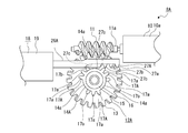
- the worm wheel 12A is formed by integrally forming a driven gear 13 and a pinion 14A (see FIG. 13).
- the pinion 14A has an annular portion 16 and gear portions 17A, 17A, 17A.
- the gear portions 17A, 17A, and 17A are provided at regular intervals in the circumferential direction.
- the gear portion 17A includes, for example, first gear teeth 17a and 17a and second gear teeth 17b.
- the gear portion 17A only needs to have at least one first gear tooth 17a and two second gear teeth 17b, and the number of the first gear teeth 17a and the second gear teeth 17b is arbitrary. is there.
- the width of the second gear teeth 17b is set to be equal to or less than half the width of the first gear teeth 17a, and is located, for example, on the driven gear 13 side.
- the second gear teeth 17b are located on the rotational direction side of the worm wheel 12A with respect to the first gear teeth 17a and 17a.
- a rack 26 ⁇ / b> A extending in the front-rear direction is connected to the connecting portion 24 of the piston 22.
- the rack 26A is formed integrally with the piston 22, for example.
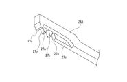
- a rack portion 27A is formed on the front end side of the rack 26A (see FIG. 14).
- the rack portion 27A is constituted by, for example, first rack teeth 27a and second rack teeth 27b, 27b, 27b.
- the rack portion 27A only needs to have at least one first rack tooth 27a and two second rack teeth 27b, and the number of the first rack teeth 27a and the second rack teeth 27b is arbitrary. is there.
- the first rack teeth 27a are located at the front end of the rack 26A.
- the second rack tooth 27b has a width equal to or less than half the width of the first rack tooth 27a, and is positioned on the side away from the driven gear 13 when the rack part 27A is engaged with the gear part 17A of the pinion 14A. ing.
- a notch portion 27c is formed continuously with the second rack tooth 27b located on the rearmost side.
- the cutout portion 27c is opened on the driven gear 13 side and below, and the rear end portion is formed in an arc shape.
- the piston 22 In the initial state, as shown in FIG. 15, the piston 22 is located at the top dead center, and the rack 26A has the first rack teeth 27a of the rack portion 27A connected to the second gear teeth 17b of the gear portion 17A of the pinion 14A. It is positioned in a meshable state or a meshed state.
- the second gear portion 17A which is different from the gear portion 17A engaged with the rack portion 27A, is moved before the piston 22 is moved to the bottom dead center.
- the gear teeth 17b are inserted into the notches 27c of the rack 26A (see FIG. 17).
- the first rack teeth 27a of the rack portion 27A can be engaged with the second gear teeth 17b of the pinion 14A again. Or it is made into the meshed state (refer FIG. 15).
- the second gear teeth 17b of the pinion 14A and the second rack teeth 27b, 27b, 27b of the rack 26A do not come into contact with each other without increasing the diameter of the pinion 14A.
- the amount of movement of the rack 26A and the piston 22 to which the rack 26A is coupled can be increased.
- the width of the second gear teeth 17b is made half or less of the width of the first gear teeth 17a, and in the rack 26A, the width of the second rack teeth 27b is equal to the width of the first rack teeth 27a. By making it half or less, the movement amount of the piston 22 can be increased without increasing the diameter of the pinion 14A.
- the manufacturing cost of the foreign matter removing apparatus 1 increases.
- the amount of movement of the piston 22 can be increased without bringing
Landscapes
- Engineering & Computer Science (AREA)
- Mechanical Engineering (AREA)
- General Engineering & Computer Science (AREA)
- Transmission Devices (AREA)
- Cleaning In General (AREA)
- Compressors, Vaccum Pumps And Other Relevant Systems (AREA)
- Multimedia (AREA)
- Nozzles (AREA)
Abstract
Description
異物除去装置1は、例えば、車輌の後方を確認する車載カメラ100に付着される水分や泥や塵埃等の異物を除去する機能を有し、図示しない車体の後端側の部分に取り付けられている。
以下に、異物除去装置1の動作について説明する(図8乃至図10参照)。
以上に記載した通り、異物除去装置1にあっては、内部に空気が流入されるシリンダー18と、シリンダー18に移動自在に支持されシリンダー18に流入された空気を高圧空気として送り出すピストン22と、ピストン22によって送り出された高圧空気を車載カメラ100の撮像部に向けて噴射するノズル6とが設けられている。
上記には、ピストン22がシリンダー10の第1の空間21aへの空気の流動及びその停止を行うバルブ(弁)として機能する例を示したが、異物除去装置1にはバルブ(チェックバルブ)が設けられてもよく、以下に、チェックバルブが設けられた例を示す(図11及び図12参照)。
以下に、移動機構の変形例について説明する(図13乃至図18参照)。尚、以下に示す変形例に係る移動機構8Aは、上記した移動機構8と比較して、ウォームホイールとラックの構造が異なることのみが相違するため、移動機構8と比較して異なる部分についてのみ詳細に説明をし、その他の部分については移動機構8における同様の部分に付した符号と同じ符号を付して説明は省略する。
Claims (14)
- 内部に空気が流入されるシリンダーと、
前記シリンダーに移動自在に支持され前記シリンダーに流入された空気を高圧空気として送出方向へ送り出すピストンと、
前記ピストンによって送り出された高圧空気を噴射するノズルとを備えた
異物除去装置。 - 前記ピストンを前記送出方向に付勢する付勢バネが設けられ、
前記ピストンに移動力を付与して前記ピストンを前記送出方向と反対方向へ所定の位置まで移動させる移動機構が設けられ、
前記ピストンが前記移動機構によって前記送出方向と反対方向へ移動されて前記付勢バネの付勢力が高められ、
前記移動機構によって前記ピストンが前記所定の位置まで移動されたときに前記移動機構による前記ピストンへの移動力の付与が解除され前記ピストンが前記付勢バネの付勢力によって前記送出方向へ移動されて前記高圧空気が送り出される
請求項1に記載の異物除去装置。 - 前記移動機構は駆動モーターの駆動力によって回転されるウォームと前記ウォームに噛合され前記ウォームの回転に伴って回転されるウォームホイールとを有し、
前記駆動モーターの駆動力が前記ウォームと前記ウォームホイールを介して前記ピストンに伝達される
請求項1又は請求項2に記載の異物除去装置。 - 前記ピストンに連結されたラックが設けられ、
前記ウォームホイールに前記ラックが噛合されるピニオンが設けられ、
前記ピニオンには外周部の一部にギヤ歯が設けられ、
前記ピニオンの外周部における前記ギヤ歯が設けられていない部分が欠歯部として形成され前記ギヤ歯が設けられた部分がギヤ部として形成された
請求項3に記載の異物除去装置。 - 前記ギヤ部が周方向に離隔して複数形成された
請求項4に記載の異物除去装置。 - 前記ピストンと前記ラックが一体に形成された
請求項4又は請求項5に記載の異物除去装置。 - 前記ピストンの中心軸と前記ラックの噛合い基準線とが略一致される
請求項4乃至請求項6の何れかに記載の異物除去装置。 - 前記ウォームの進み角が9°以上にされた
請求項4乃至請求項7の何れかに記載の異物除去装置。 - 前記ギヤ部には複数の前記ギヤ歯が設けられ、
前記ラックには複数のラック歯が設けられ、
前記複数のギヤ歯は第1のギヤ歯と第2のギヤ歯から成り、
前記複数のラック歯は第1のラック歯と第2のラック歯から成り、
前記第1のギヤ歯は前記第1のラック歯及び前記第2のラック歯と噛合可能とされ、
前記第2のギヤ歯は前記第1のラック歯と噛合可能とされると共に前記第2のラック歯と噛合不能とされ、
前記ピストンの前記送出方向への移動に伴って前記ラックが移動されると共に前記ウォームホイールが回転されたときに、前記第2のギヤ歯と前記第2のラック歯がすれ違うようにされた
請求項4乃至請求項8の何れかに記載の異物除去装置。 - 前記第2のギヤ歯の幅が前記第1のギヤ歯の幅の半分以下にされ、
前記第2のラック歯の幅が前記第1のラック歯の幅の半分以下にされた
請求項9に記載の異物除去装置。 - 前記シリンダーの内部空間は前記ピストンの移動方向において連続する第1の空間と第2の空間を有し前記第1の空間が前記第2の空間より前記送出方向側に位置され、
前記第2の空間の少なくとも一部の径が前記第1の空間の径より大きくされ、
前記ピストンには移動時に少なくとも前記第1の空間において前記シリンダーの内周面に密着されるシール部が設けられ、
前記ピストンが下死点に移動されたときに前記シール部の全体が前記第2の空間に位置され前記第2の空間に流入される空気が前記第2の空間から前記第1の空間へ向けて流動される
請求項1乃至請求項10の何れかに記載の異物除去装置。 - 前記第2の空間には外周側に前記ピストンの移動方向に延びる空気流入溝が形成され、
前記空気流入溝が前記一部として形成された
請求項11に記載の異物除去装置。 - 前記空気流入溝が周方向に離隔して等間隔の状態で複数形成された
請求項12に記載の異物除去装置。 - 前記ノズルから高圧空気が車載カメラの撮像部に向けて噴射され、
前記ノズルが前記車載カメラと一体に形成された
請求項1乃至請求項13の何れかに記載の異物除去装置。
Priority Applications (5)
| Application Number | Priority Date | Filing Date | Title |
|---|---|---|---|
| EP15779331.6A EP3132984B1 (en) | 2014-04-14 | 2015-04-07 | In vehicle device with foreign material removal |
| US15/303,972 US10436186B2 (en) | 2014-04-14 | 2015-04-07 | Foreign material removal device |
| JP2016513730A JP6712436B2 (ja) | 2014-04-14 | 2015-04-07 | 異物除去装置 |
| CN201580019594.3A CN106163888B (zh) | 2014-04-14 | 2015-04-07 | 异物除去装置 |
| US16/539,018 US11225224B2 (en) | 2014-04-14 | 2019-08-13 | Foreign material removal device |
Applications Claiming Priority (8)
| Application Number | Priority Date | Filing Date | Title |
|---|---|---|---|
| JP2014-082987 | 2014-04-14 | ||
| JP2014082986 | 2014-04-14 | ||
| JP2014082988 | 2014-04-14 | ||
| JP2014082987 | 2014-04-14 | ||
| JP2014-082988 | 2014-04-14 | ||
| JP2014-082986 | 2014-04-14 | ||
| JP2015024478 | 2015-02-10 | ||
| JP2015-024478 | 2015-11-02 |
Related Child Applications (2)
| Application Number | Title | Priority Date | Filing Date |
|---|---|---|---|
| US15/303,972 A-371-Of-International US10436186B2 (en) | 2014-04-14 | 2015-04-07 | Foreign material removal device |
| US16/539,018 Continuation US11225224B2 (en) | 2014-04-14 | 2019-08-13 | Foreign material removal device |
Publications (1)
| Publication Number | Publication Date |
|---|---|
| WO2015159763A1 true WO2015159763A1 (ja) | 2015-10-22 |
Family
ID=54323974
Family Applications (1)
| Application Number | Title | Priority Date | Filing Date |
|---|---|---|---|
| PCT/JP2015/060877 Ceased WO2015159763A1 (ja) | 2014-04-14 | 2015-04-07 | 異物除去装置 |
Country Status (5)
| Country | Link |
|---|---|
| US (2) | US10436186B2 (ja) |
| EP (1) | EP3132984B1 (ja) |
| JP (1) | JP6712436B2 (ja) |
| CN (1) | CN106163888B (ja) |
| WO (1) | WO2015159763A1 (ja) |
Cited By (18)
| Publication number | Priority date | Publication date | Assignee | Title |
|---|---|---|---|---|
| WO2016104050A1 (ja) * | 2014-12-22 | 2016-06-30 | 株式会社小糸製作所 | 異物除去装置、除去駆動装置 |
| CN105847760A (zh) * | 2016-05-20 | 2016-08-10 | 温州电力设计有限公司 | 一种图像监控装置 |
| WO2017002878A1 (ja) * | 2015-06-30 | 2017-01-05 | 株式会社小糸製作所 | 異物除去装置および当該異物除去装置を備える車両 |
| WO2017002879A1 (ja) * | 2015-06-30 | 2017-01-05 | 株式会社小糸製作所 | 異物除去装置および当該異物除去装置を備える車両 |
| WO2017002877A1 (ja) * | 2015-06-30 | 2017-01-05 | 株式会社小糸製作所 | 異物除去装置および当該異物除去装置を備える車両 |
| WO2017002688A1 (ja) * | 2015-06-30 | 2017-01-05 | 株式会社小糸製作所 | 異物除去装置および当該異物除去装置を備える車両 |
| JP2017101653A (ja) * | 2015-11-19 | 2017-06-08 | アスモ株式会社 | 電動エアポンプ |
| JP2017149310A (ja) * | 2016-02-25 | 2017-08-31 | 株式会社富士通ゼネラル | 水滴除去機構とこれを備えた車載カメラ |
| JP2018053877A (ja) * | 2016-09-30 | 2018-04-05 | アスモ株式会社 | 電動エアポンプ及び車載光学センサ洗浄装置 |
| US20180167536A1 (en) * | 2016-12-12 | 2018-06-14 | Koito Manufacturing Co., Ltd. | Cleaner and vehicle with cleaner |
| JP2018144542A (ja) * | 2017-03-02 | 2018-09-20 | 株式会社ホンダアクセス | 噴射用ノズル部材 |
| WO2019044389A1 (ja) * | 2017-08-28 | 2019-03-07 | 株式会社小糸製作所 | 異物除去装置 |
| US10814838B2 (en) | 2016-03-31 | 2020-10-27 | Denso Corporation | Onboard optical sensor cleaning device |
| US10941756B2 (en) | 2018-08-31 | 2021-03-09 | Denso Ten Limited | Compressor |
| JP2022517576A (ja) * | 2019-01-31 | 2022-03-09 | セムチャン エナジー カンパニー リミテッド | 水素ガス圧縮装置 |
| DE112016001913B4 (de) | 2015-12-28 | 2022-03-17 | Fujitsu Ten Limited | Fremdmaterial-Beseitigungsgerät |
| DE112018002899B4 (de) | 2017-06-09 | 2022-09-01 | Denso Corporation | Elektrische Pumpenvorrichtung |
| JP2023170161A (ja) * | 2022-05-18 | 2023-12-01 | 株式会社デンソーテン | 気体噴射装置 |
Families Citing this family (5)
| Publication number | Priority date | Publication date | Assignee | Title |
|---|---|---|---|---|
| WO2018123517A1 (ja) | 2016-12-28 | 2018-07-05 | 株式会社小糸製作所 | 車両用クリーナシステムおよび車両用クリーナシステムを備える車両、車両用クリーナおよび車両用クリーナを備える車両 |
| JP6764385B2 (ja) | 2017-01-20 | 2020-09-30 | 株式会社ニフコ | 車両用カメラに対する流体の吹き付け装置 |
| JP6977514B2 (ja) | 2017-06-09 | 2021-12-08 | 株式会社デンソー | 車載センサ洗浄装置 |
| CN114291037B (zh) * | 2020-10-07 | 2025-03-07 | 株式会社小糸制作所 | 车辆清洗装置、其制造方法及其组装方法 |
| JPWO2024142274A1 (ja) * | 2022-12-27 | 2024-07-04 |
Citations (12)
| Publication number | Priority date | Publication date | Assignee | Title |
|---|---|---|---|---|
| JPH03102652A (ja) * | 1989-09-18 | 1991-04-30 | Canon Inc | 光学的情報記録再生装置 |
| JPH05184546A (ja) * | 1992-01-08 | 1993-07-27 | Canon Inc | 非接触眼圧計 |
| JPH07121896A (ja) * | 1993-10-28 | 1995-05-12 | Nec Corp | 光ディスク装置 |
| JP2001171491A (ja) * | 1999-12-16 | 2001-06-26 | Matsushita Electric Ind Co Ltd | 車載カメラ装置及び車載カメラの洗浄方法 |
| JP2004202145A (ja) * | 2002-12-26 | 2004-07-22 | Yamanouchi Trading:Kk | エアガン用ピストンシリンダ装置及びエアガン |
| JP2005138756A (ja) * | 2003-11-07 | 2005-06-02 | Honda Motor Co Ltd | 車両のシートベルト装置 |
| JP2007315030A (ja) * | 2006-05-25 | 2007-12-06 | Kidoh Tech Co Ltd | 石綿管の撤去方法 |
| JP3137755U (ja) * | 2007-09-26 | 2007-12-06 | 高浩 浦 | 弾接触面を有するノズル、弾の発射装置及び玩具空気銃 |
| JP2008213007A (ja) * | 2007-03-07 | 2008-09-18 | Eiji Suga | 自動組立装置における制御装置 |
| JP2012504987A (ja) * | 2008-10-14 | 2012-03-01 | フェルトン ホールディング エスアー | 生体への衝撃波導入装置及びその利用 |
| EP2631734A1 (en) * | 2012-02-23 | 2013-08-28 | The Raymond Corporation | Method and apparatus for removing and preventing lens surface fogging on a vehicle lens |
| JP2014166806A (ja) * | 2013-02-28 | 2014-09-11 | Mitsubishi Heavy Ind Ltd | 管内走行装置及び管内検査装置 |
Family Cites Families (6)
| Publication number | Priority date | Publication date | Assignee | Title |
|---|---|---|---|---|
| US2260113A (en) * | 1940-02-19 | 1941-10-21 | Frost Orley Ray | Vacuum pump control |
| US2309339A (en) * | 1941-05-21 | 1943-01-26 | Akron Lamp & Mfg Company | Pump |
| JP3934302B2 (ja) * | 2000-03-27 | 2007-06-20 | ミナミ株式会社 | 実装プリント配線基板の部品に塗布した腐食防止固定材の真空脱泡装置 |
| US20100167236A1 (en) * | 2008-12-29 | 2010-07-01 | Koninklijke Philips Electronics N.V. | Non-pressurized system fore creating liquid droplets in a dental cleaning appliance |
| BR112013007026A2 (pt) | 2010-09-29 | 2020-10-13 | Koninklijke Philips Electronics N.V | aparelho para uso em um sistema de gotículas de líquido para limpeza dos dentes, para produção de impulsos sucessivos de ar e impulsos sucessivos de líquido com um conjunto de motor |
| US20140023537A1 (en) * | 2012-07-19 | 2014-01-23 | Wei-Chi Wang | Air Pump Cylinder |
-
2015
- 2015-04-07 CN CN201580019594.3A patent/CN106163888B/zh active Active
- 2015-04-07 EP EP15779331.6A patent/EP3132984B1/en active Active
- 2015-04-07 WO PCT/JP2015/060877 patent/WO2015159763A1/ja not_active Ceased
- 2015-04-07 US US15/303,972 patent/US10436186B2/en active Active
- 2015-04-07 JP JP2016513730A patent/JP6712436B2/ja active Active
-
2019
- 2019-08-13 US US16/539,018 patent/US11225224B2/en active Active
Patent Citations (12)
| Publication number | Priority date | Publication date | Assignee | Title |
|---|---|---|---|---|
| JPH03102652A (ja) * | 1989-09-18 | 1991-04-30 | Canon Inc | 光学的情報記録再生装置 |
| JPH05184546A (ja) * | 1992-01-08 | 1993-07-27 | Canon Inc | 非接触眼圧計 |
| JPH07121896A (ja) * | 1993-10-28 | 1995-05-12 | Nec Corp | 光ディスク装置 |
| JP2001171491A (ja) * | 1999-12-16 | 2001-06-26 | Matsushita Electric Ind Co Ltd | 車載カメラ装置及び車載カメラの洗浄方法 |
| JP2004202145A (ja) * | 2002-12-26 | 2004-07-22 | Yamanouchi Trading:Kk | エアガン用ピストンシリンダ装置及びエアガン |
| JP2005138756A (ja) * | 2003-11-07 | 2005-06-02 | Honda Motor Co Ltd | 車両のシートベルト装置 |
| JP2007315030A (ja) * | 2006-05-25 | 2007-12-06 | Kidoh Tech Co Ltd | 石綿管の撤去方法 |
| JP2008213007A (ja) * | 2007-03-07 | 2008-09-18 | Eiji Suga | 自動組立装置における制御装置 |
| JP3137755U (ja) * | 2007-09-26 | 2007-12-06 | 高浩 浦 | 弾接触面を有するノズル、弾の発射装置及び玩具空気銃 |
| JP2012504987A (ja) * | 2008-10-14 | 2012-03-01 | フェルトン ホールディング エスアー | 生体への衝撃波導入装置及びその利用 |
| EP2631734A1 (en) * | 2012-02-23 | 2013-08-28 | The Raymond Corporation | Method and apparatus for removing and preventing lens surface fogging on a vehicle lens |
| JP2014166806A (ja) * | 2013-02-28 | 2014-09-11 | Mitsubishi Heavy Ind Ltd | 管内走行装置及び管内検査装置 |
Non-Patent Citations (1)
| Title |
|---|
| See also references of EP3132984A4 * |
Cited By (42)
| Publication number | Priority date | Publication date | Assignee | Title |
|---|---|---|---|---|
| JPWO2016104050A1 (ja) * | 2014-12-22 | 2017-09-28 | 株式会社小糸製作所 | 異物除去装置、除去駆動装置 |
| US11230271B2 (en) | 2014-12-22 | 2022-01-25 | Koito Manufacturing Co., Ltd. | Foreign body removal device and drive device for foreign body removal device |
| WO2016104050A1 (ja) * | 2014-12-22 | 2016-06-30 | 株式会社小糸製作所 | 異物除去装置、除去駆動装置 |
| JPWO2017002877A1 (ja) * | 2015-06-30 | 2018-04-19 | 株式会社小糸製作所 | 異物除去装置および当該異物除去装置を備える車両 |
| JPWO2017002879A1 (ja) * | 2015-06-30 | 2018-04-26 | 株式会社小糸製作所 | 異物除去装置および当該異物除去装置を備える車両 |
| WO2017002688A1 (ja) * | 2015-06-30 | 2017-01-05 | 株式会社小糸製作所 | 異物除去装置および当該異物除去装置を備える車両 |
| US10661761B2 (en) | 2015-06-30 | 2020-05-26 | Koito Manufacturing Co., Ltd. | Foreign matter removal device and vehicle equipped with foreign matter removal device |
| US10604122B2 (en) | 2015-06-30 | 2020-03-31 | Koito Manufacturing Co., Ltd. | Foreign matter removal device and vehicle provided with same |
| WO2017002879A1 (ja) * | 2015-06-30 | 2017-01-05 | 株式会社小糸製作所 | 異物除去装置および当該異物除去装置を備える車両 |
| US11155244B2 (en) | 2015-06-30 | 2021-10-26 | Koito Manufacturing Co., Ltd. | Foreign material removing device and vehicle provided with this foreign material removing device |
| WO2017002878A1 (ja) * | 2015-06-30 | 2017-01-05 | 株式会社小糸製作所 | 異物除去装置および当該異物除去装置を備える車両 |
| JPWO2017002878A1 (ja) * | 2015-06-30 | 2018-04-26 | 株式会社小糸製作所 | 異物除去装置および当該異物除去装置を備える車両 |
| WO2017002877A1 (ja) * | 2015-06-30 | 2017-01-05 | 株式会社小糸製作所 | 異物除去装置および当該異物除去装置を備える車両 |
| US10556571B2 (en) | 2015-06-30 | 2020-02-11 | Koito Manufacturing Co., Ltd. | Foreign matter removal device and vehicle equipped with foreign matter removal device |
| US11827188B2 (en) | 2015-06-30 | 2023-11-28 | Koito Manufacturing Co., Ltd. | Foreign material removing device and vehicle provided with this foreign material removing device |
| JPWO2017002688A1 (ja) * | 2015-06-30 | 2018-06-21 | 株式会社小糸製作所 | 異物除去装置および当該異物除去装置を備える車両 |
| JP2018114974A (ja) * | 2015-06-30 | 2018-07-26 | 株式会社小糸製作所 | 異物除去装置および当該異物除去装置を備える車両 |
| US11505163B2 (en) | 2015-06-30 | 2022-11-22 | Koito Manufacturing Co., Ltd. | Foreign matter removal device and vehicle equipped with foreign matter removal device |
| US20180372078A1 (en) * | 2015-11-19 | 2018-12-27 | Denso Corporation | Electric air pump |
| JP2017101653A (ja) * | 2015-11-19 | 2017-06-08 | アスモ株式会社 | 電動エアポンプ |
| US10788027B2 (en) * | 2015-11-19 | 2020-09-29 | Denso Corporation | Electric air pump |
| DE112016001913B4 (de) | 2015-12-28 | 2022-03-17 | Fujitsu Ten Limited | Fremdmaterial-Beseitigungsgerät |
| JP2017149310A (ja) * | 2016-02-25 | 2017-08-31 | 株式会社富士通ゼネラル | 水滴除去機構とこれを備えた車載カメラ |
| US10814838B2 (en) | 2016-03-31 | 2020-10-27 | Denso Corporation | Onboard optical sensor cleaning device |
| CN105847760B (zh) * | 2016-05-20 | 2019-03-05 | 温州电力设计有限公司 | 一种图像监控装置 |
| CN105847760A (zh) * | 2016-05-20 | 2016-08-10 | 温州电力设计有限公司 | 一种图像监控装置 |
| JP2018053877A (ja) * | 2016-09-30 | 2018-04-05 | アスモ株式会社 | 電動エアポンプ及び車載光学センサ洗浄装置 |
| US20180167536A1 (en) * | 2016-12-12 | 2018-06-14 | Koito Manufacturing Co., Ltd. | Cleaner and vehicle with cleaner |
| JP2018095033A (ja) * | 2016-12-12 | 2018-06-21 | 株式会社小糸製作所 | クリーナおよびクリーナを備える車両 |
| US10587784B2 (en) * | 2016-12-12 | 2020-03-10 | Koito Manufacturing Co., Ltd. | Cleaner and vehicle with cleaner |
| DE102018203115B4 (de) | 2017-03-02 | 2025-10-02 | Honda Access Corp. | Ejektionsdüsenelement |
| JP2018144542A (ja) * | 2017-03-02 | 2018-09-20 | 株式会社ホンダアクセス | 噴射用ノズル部材 |
| DE112018002899B4 (de) | 2017-06-09 | 2022-09-01 | Denso Corporation | Elektrische Pumpenvorrichtung |
| JPWO2019044389A1 (ja) * | 2017-08-28 | 2020-08-06 | 株式会社小糸製作所 | 異物除去装置 |
| WO2019044389A1 (ja) * | 2017-08-28 | 2019-03-07 | 株式会社小糸製作所 | 異物除去装置 |
| US11344926B2 (en) | 2017-08-28 | 2022-05-31 | Koito Manufacturing Co., Ltd. | Foreign substance removing device |
| JP7182551B2 (ja) | 2017-08-28 | 2022-12-02 | 株式会社小糸製作所 | 異物除去装置 |
| US10941756B2 (en) | 2018-08-31 | 2021-03-09 | Denso Ten Limited | Compressor |
| JP2022517576A (ja) * | 2019-01-31 | 2022-03-09 | セムチャン エナジー カンパニー リミテッド | 水素ガス圧縮装置 |
| JP7609437B2 (ja) | 2019-01-31 | 2025-01-07 | セムチャン エナジー カンパニー リミテッド | 水素ガス圧縮装置 |
| US20220268264A1 (en) * | 2019-01-31 | 2022-08-25 | Saemchan Energy Co., Ltd. | Hydrogen gas compression device |
| JP2023170161A (ja) * | 2022-05-18 | 2023-12-01 | 株式会社デンソーテン | 気体噴射装置 |
Also Published As
| Publication number | Publication date |
|---|---|
| US10436186B2 (en) | 2019-10-08 |
| CN106163888B (zh) | 2019-06-28 |
| US20170028968A1 (en) | 2017-02-02 |
| CN106163888A (zh) | 2016-11-23 |
| EP3132984B1 (en) | 2019-11-20 |
| JPWO2015159763A1 (ja) | 2017-04-13 |
| JP6712436B2 (ja) | 2020-06-24 |
| US20190359180A1 (en) | 2019-11-28 |
| EP3132984A4 (en) | 2018-04-04 |
| US11225224B2 (en) | 2022-01-18 |
| EP3132984A1 (en) | 2017-02-22 |
Similar Documents
| Publication | Publication Date | Title |
|---|---|---|
| JP6712436B2 (ja) | 異物除去装置 | |
| JP7358595B2 (ja) | 車両用クリーナシステムおよび車両用クリーナシステムを備える車両 | |
| JP6417757B2 (ja) | 車載光学センサ洗浄装置 | |
| JP6771876B2 (ja) | 自動車の走行支援カメラ用クリーニング装置 | |
| JP6654145B2 (ja) | 異物除去装置、除去駆動装置 | |
| US20210362689A1 (en) | Foreign material removing device and vehicle provided with this foreign material removing device | |
| JP7555707B2 (ja) | ライセンスプレートランプユニットおよびライセンスプレートランプユニットを備える車両 | |
| CN108238009B (zh) | 清洗器和包括清洗器的车辆 | |
| JP7182551B2 (ja) | 異物除去装置 | |
| WO2026083798A1 (ja) | クリーナ | |
| JP2026071140A (ja) | クリーナ | |
| JP2022157200A (ja) | 噴射装置および噴射方法 |
Legal Events
| Date | Code | Title | Description |
|---|---|---|---|
| 121 | Ep: the epo has been informed by wipo that ep was designated in this application |
Ref document number: 15779331 Country of ref document: EP Kind code of ref document: A1 |
|
| ENP | Entry into the national phase |
Ref document number: 2016513730 Country of ref document: JP Kind code of ref document: A |
|
| WWE | Wipo information: entry into national phase |
Ref document number: 15303972 Country of ref document: US |
|
| NENP | Non-entry into the national phase |
Ref country code: DE |
|
| REEP | Request for entry into the european phase |
Ref document number: 2015779331 Country of ref document: EP |
|
| WWE | Wipo information: entry into national phase |
Ref document number: 2015779331 Country of ref document: EP |