WO2015159838A1 - 多孔質板状フィラー、断熱膜、及び多孔質板状フィラーの製造方法 - Google Patents
多孔質板状フィラー、断熱膜、及び多孔質板状フィラーの製造方法 Download PDFInfo
- Publication number
- WO2015159838A1 WO2015159838A1 PCT/JP2015/061319 JP2015061319W WO2015159838A1 WO 2015159838 A1 WO2015159838 A1 WO 2015159838A1 JP 2015061319 W JP2015061319 W JP 2015061319W WO 2015159838 A1 WO2015159838 A1 WO 2015159838A1
- Authority
- WO
- WIPO (PCT)
- Prior art keywords
- filler
- porous plate
- plate
- heat insulating
- insulating film
- Prior art date
- Legal status (The legal status is an assumption and is not a legal conclusion. Google has not performed a legal analysis and makes no representation as to the accuracy of the status listed.)
- Ceased
Links
Images



Classifications
-
- C—CHEMISTRY; METALLURGY
- C09—DYES; PAINTS; POLISHES; NATURAL RESINS; ADHESIVES; COMPOSITIONS NOT OTHERWISE PROVIDED FOR; APPLICATIONS OF MATERIALS NOT OTHERWISE PROVIDED FOR
- C09D—COATING COMPOSITIONS, e.g. PAINTS, VARNISHES OR LACQUERS; FILLING PASTES; CHEMICAL PAINT OR INK REMOVERS; INKS; CORRECTING FLUIDS; WOODSTAINS; PASTES OR SOLIDS FOR COLOURING OR PRINTING; USE OF MATERIALS THEREFOR
- C09D7/00—Features of coating compositions, not provided for in group C09D5/00; Processes for incorporating ingredients in coating compositions
- C09D7/40—Additives
- C09D7/60—Additives non-macromolecular
- C09D7/61—Additives non-macromolecular inorganic
- C09D7/62—Additives non-macromolecular inorganic modified by treatment with other compounds
-
- C—CHEMISTRY; METALLURGY
- C04—CEMENTS; CONCRETE; ARTIFICIAL STONE; CERAMICS; REFRACTORIES
- C04B—LIME, MAGNESIA; SLAG; CEMENTS; COMPOSITIONS THEREOF, e.g. MORTARS, CONCRETE OR LIKE BUILDING MATERIALS; ARTIFICIAL STONE; CERAMICS; REFRACTORIES; TREATMENT OF NATURAL STONE
- C04B38/00—Porous mortars, concrete, artificial stone or ceramic ware; Preparation thereof
-
- C—CHEMISTRY; METALLURGY
- C04—CEMENTS; CONCRETE; ARTIFICIAL STONE; CERAMICS; REFRACTORIES
- C04B—LIME, MAGNESIA; SLAG; CEMENTS; COMPOSITIONS THEREOF, e.g. MORTARS, CONCRETE OR LIKE BUILDING MATERIALS; ARTIFICIAL STONE; CERAMICS; REFRACTORIES; TREATMENT OF NATURAL STONE
- C04B38/00—Porous mortars, concrete, artificial stone or ceramic ware; Preparation thereof
- C04B38/06—Porous mortars, concrete, artificial stone or ceramic ware; Preparation thereof by burning-out added substances by burning natural expanding materials or by sublimating or melting out added substances
-
- C—CHEMISTRY; METALLURGY
- C09—DYES; PAINTS; POLISHES; NATURAL RESINS; ADHESIVES; COMPOSITIONS NOT OTHERWISE PROVIDED FOR; APPLICATIONS OF MATERIALS NOT OTHERWISE PROVIDED FOR
- C09C—TREATMENT OF INORGANIC MATERIALS, OTHER THAN FIBROUS FILLERS, TO ENHANCE THEIR PIGMENTING OR FILLING PROPERTIES ; PREPARATION OF CARBON BLACK ; PREPARATION OF INORGANIC MATERIALS WHICH ARE NO SINGLE CHEMICAL COMPOUNDS AND WHICH ARE MAINLY USED AS PIGMENTS OR FILLERS
- C09C1/00—Treatment of specific inorganic materials other than fibrous fillers; Preparation of carbon black
-
- C—CHEMISTRY; METALLURGY
- C09—DYES; PAINTS; POLISHES; NATURAL RESINS; ADHESIVES; COMPOSITIONS NOT OTHERWISE PROVIDED FOR; APPLICATIONS OF MATERIALS NOT OTHERWISE PROVIDED FOR
- C09C—TREATMENT OF INORGANIC MATERIALS, OTHER THAN FIBROUS FILLERS, TO ENHANCE THEIR PIGMENTING OR FILLING PROPERTIES ; PREPARATION OF CARBON BLACK ; PREPARATION OF INORGANIC MATERIALS WHICH ARE NO SINGLE CHEMICAL COMPOUNDS AND WHICH ARE MAINLY USED AS PIGMENTS OR FILLERS
- C09C1/00—Treatment of specific inorganic materials other than fibrous fillers; Preparation of carbon black
- C09C1/28—Compounds of silicon
- C09C1/30—Silicic acid
- C09C1/309—Combinations of treatments provided for in groups C09C1/3009 - C09C1/3081
-
- C—CHEMISTRY; METALLURGY
- C09—DYES; PAINTS; POLISHES; NATURAL RESINS; ADHESIVES; COMPOSITIONS NOT OTHERWISE PROVIDED FOR; APPLICATIONS OF MATERIALS NOT OTHERWISE PROVIDED FOR
- C09C—TREATMENT OF INORGANIC MATERIALS, OTHER THAN FIBROUS FILLERS, TO ENHANCE THEIR PIGMENTING OR FILLING PROPERTIES ; PREPARATION OF CARBON BLACK ; PREPARATION OF INORGANIC MATERIALS WHICH ARE NO SINGLE CHEMICAL COMPOUNDS AND WHICH ARE MAINLY USED AS PIGMENTS OR FILLERS
- C09C1/00—Treatment of specific inorganic materials other than fibrous fillers; Preparation of carbon black
- C09C1/36—Compounds of titanium
- C09C1/3607—Titanium dioxide
-
- C—CHEMISTRY; METALLURGY
- C09—DYES; PAINTS; POLISHES; NATURAL RESINS; ADHESIVES; COMPOSITIONS NOT OTHERWISE PROVIDED FOR; APPLICATIONS OF MATERIALS NOT OTHERWISE PROVIDED FOR
- C09C—TREATMENT OF INORGANIC MATERIALS, OTHER THAN FIBROUS FILLERS, TO ENHANCE THEIR PIGMENTING OR FILLING PROPERTIES ; PREPARATION OF CARBON BLACK ; PREPARATION OF INORGANIC MATERIALS WHICH ARE NO SINGLE CHEMICAL COMPOUNDS AND WHICH ARE MAINLY USED AS PIGMENTS OR FILLERS
- C09C1/00—Treatment of specific inorganic materials other than fibrous fillers; Preparation of carbon black
- C09C1/40—Compounds of aluminium
- C09C1/407—Aluminium oxides or hydroxides
-
- C—CHEMISTRY; METALLURGY
- C09—DYES; PAINTS; POLISHES; NATURAL RESINS; ADHESIVES; COMPOSITIONS NOT OTHERWISE PROVIDED FOR; APPLICATIONS OF MATERIALS NOT OTHERWISE PROVIDED FOR
- C09C—TREATMENT OF INORGANIC MATERIALS, OTHER THAN FIBROUS FILLERS, TO ENHANCE THEIR PIGMENTING OR FILLING PROPERTIES ; PREPARATION OF CARBON BLACK ; PREPARATION OF INORGANIC MATERIALS WHICH ARE NO SINGLE CHEMICAL COMPOUNDS AND WHICH ARE MAINLY USED AS PIGMENTS OR FILLERS
- C09C3/00—Treatment in general of inorganic materials, other than fibrous fillers, to enhance their pigmenting or filling properties
-
- C—CHEMISTRY; METALLURGY
- C09—DYES; PAINTS; POLISHES; NATURAL RESINS; ADHESIVES; COMPOSITIONS NOT OTHERWISE PROVIDED FOR; APPLICATIONS OF MATERIALS NOT OTHERWISE PROVIDED FOR
- C09C—TREATMENT OF INORGANIC MATERIALS, OTHER THAN FIBROUS FILLERS, TO ENHANCE THEIR PIGMENTING OR FILLING PROPERTIES ; PREPARATION OF CARBON BLACK ; PREPARATION OF INORGANIC MATERIALS WHICH ARE NO SINGLE CHEMICAL COMPOUNDS AND WHICH ARE MAINLY USED AS PIGMENTS OR FILLERS
- C09C3/00—Treatment in general of inorganic materials, other than fibrous fillers, to enhance their pigmenting or filling properties
- C09C3/04—Physical treatment, e.g. grinding or treatment with ultrasonic vibrations
- C09C3/043—Drying, calcination
-
- C—CHEMISTRY; METALLURGY
- C09—DYES; PAINTS; POLISHES; NATURAL RESINS; ADHESIVES; COMPOSITIONS NOT OTHERWISE PROVIDED FOR; APPLICATIONS OF MATERIALS NOT OTHERWISE PROVIDED FOR
- C09C—TREATMENT OF INORGANIC MATERIALS, OTHER THAN FIBROUS FILLERS, TO ENHANCE THEIR PIGMENTING OR FILLING PROPERTIES ; PREPARATION OF CARBON BLACK ; PREPARATION OF INORGANIC MATERIALS WHICH ARE NO SINGLE CHEMICAL COMPOUNDS AND WHICH ARE MAINLY USED AS PIGMENTS OR FILLERS
- C09C3/00—Treatment in general of inorganic materials, other than fibrous fillers, to enhance their pigmenting or filling properties
- C09C3/06—Treatment with inorganic compounds
-
- C—CHEMISTRY; METALLURGY
- C09—DYES; PAINTS; POLISHES; NATURAL RESINS; ADHESIVES; COMPOSITIONS NOT OTHERWISE PROVIDED FOR; APPLICATIONS OF MATERIALS NOT OTHERWISE PROVIDED FOR
- C09C—TREATMENT OF INORGANIC MATERIALS, OTHER THAN FIBROUS FILLERS, TO ENHANCE THEIR PIGMENTING OR FILLING PROPERTIES ; PREPARATION OF CARBON BLACK ; PREPARATION OF INORGANIC MATERIALS WHICH ARE NO SINGLE CHEMICAL COMPOUNDS AND WHICH ARE MAINLY USED AS PIGMENTS OR FILLERS
- C09C3/00—Treatment in general of inorganic materials, other than fibrous fillers, to enhance their pigmenting or filling properties
- C09C3/10—Treatment with macromolecular organic compounds
-
- C—CHEMISTRY; METALLURGY
- C09—DYES; PAINTS; POLISHES; NATURAL RESINS; ADHESIVES; COMPOSITIONS NOT OTHERWISE PROVIDED FOR; APPLICATIONS OF MATERIALS NOT OTHERWISE PROVIDED FOR
- C09D—COATING COMPOSITIONS, e.g. PAINTS, VARNISHES OR LACQUERS; FILLING PASTES; CHEMICAL PAINT OR INK REMOVERS; INKS; CORRECTING FLUIDS; WOODSTAINS; PASTES OR SOLIDS FOR COLOURING OR PRINTING; USE OF MATERIALS THEREFOR
- C09D183/00—Coating compositions based on macromolecular compounds obtained by reactions forming in the main chain of the macromolecule a linkage containing silicon, with or without sulfur, nitrogen, oxygen, or carbon only; Coating compositions based on derivatives of such polymers
- C09D183/04—Polysiloxanes
-
- C—CHEMISTRY; METALLURGY
- C09—DYES; PAINTS; POLISHES; NATURAL RESINS; ADHESIVES; COMPOSITIONS NOT OTHERWISE PROVIDED FOR; APPLICATIONS OF MATERIALS NOT OTHERWISE PROVIDED FOR
- C09D—COATING COMPOSITIONS, e.g. PAINTS, VARNISHES OR LACQUERS; FILLING PASTES; CHEMICAL PAINT OR INK REMOVERS; INKS; CORRECTING FLUIDS; WOODSTAINS; PASTES OR SOLIDS FOR COLOURING OR PRINTING; USE OF MATERIALS THEREFOR
- C09D201/00—Coating compositions based on unspecified macromolecular compounds
-
- C—CHEMISTRY; METALLURGY
- C09—DYES; PAINTS; POLISHES; NATURAL RESINS; ADHESIVES; COMPOSITIONS NOT OTHERWISE PROVIDED FOR; APPLICATIONS OF MATERIALS NOT OTHERWISE PROVIDED FOR
- C09D—COATING COMPOSITIONS, e.g. PAINTS, VARNISHES OR LACQUERS; FILLING PASTES; CHEMICAL PAINT OR INK REMOVERS; INKS; CORRECTING FLUIDS; WOODSTAINS; PASTES OR SOLIDS FOR COLOURING OR PRINTING; USE OF MATERIALS THEREFOR
- C09D7/00—Features of coating compositions, not provided for in group C09D5/00; Processes for incorporating ingredients in coating compositions
- C09D7/40—Additives
-
- F—MECHANICAL ENGINEERING; LIGHTING; HEATING; WEAPONS; BLASTING
- F16—ENGINEERING ELEMENTS AND UNITS; GENERAL MEASURES FOR PRODUCING AND MAINTAINING EFFECTIVE FUNCTIONING OF MACHINES OR INSTALLATIONS; THERMAL INSULATION IN GENERAL
- F16L—PIPES; JOINTS OR FITTINGS FOR PIPES; SUPPORTS FOR PIPES, CABLES OR PROTECTIVE TUBING; MEANS FOR THERMAL INSULATION IN GENERAL
- F16L59/00—Thermal insulation in general
- F16L59/02—Shape or form of insulating materials, with or without coverings integral with the insulating materials
- F16L59/028—Compositions for or methods of fixing a thermally insulating material
-
- C—CHEMISTRY; METALLURGY
- C01—INORGANIC CHEMISTRY
- C01P—INDEXING SCHEME RELATING TO STRUCTURAL AND PHYSICAL ASPECTS OF SOLID INORGANIC COMPOUNDS
- C01P2004/00—Particle morphology
- C01P2004/20—Particle morphology extending in two dimensions, e.g. plate-like
- C01P2004/24—Nanoplates, i.e. plate-like particles with a thickness from 1-100 nanometer
-
- C—CHEMISTRY; METALLURGY
- C01—INORGANIC CHEMISTRY
- C01P—INDEXING SCHEME RELATING TO STRUCTURAL AND PHYSICAL ASPECTS OF SOLID INORGANIC COMPOUNDS
- C01P2006/00—Physical properties of inorganic compounds
- C01P2006/32—Thermal properties
-
- C—CHEMISTRY; METALLURGY
- C04—CEMENTS; CONCRETE; ARTIFICIAL STONE; CERAMICS; REFRACTORIES
- C04B—LIME, MAGNESIA; SLAG; CEMENTS; COMPOSITIONS THEREOF, e.g. MORTARS, CONCRETE OR LIKE BUILDING MATERIALS; ARTIFICIAL STONE; CERAMICS; REFRACTORIES; TREATMENT OF NATURAL STONE
- C04B35/00—Shaped ceramic products characterised by their composition; Ceramics compositions; Processing powders of inorganic compounds preparatory to the manufacturing of ceramic products
- C04B35/01—Shaped ceramic products characterised by their composition; Ceramics compositions; Processing powders of inorganic compounds preparatory to the manufacturing of ceramic products based on oxide ceramics
- C04B35/48—Shaped ceramic products characterised by their composition; Ceramics compositions; Processing powders of inorganic compounds preparatory to the manufacturing of ceramic products based on oxide ceramics based on zirconium or hafnium oxides, zirconates, zircon or hafnates
Definitions
- the present invention relates to a porous plate filler for forming a heat insulating film with improved heat insulating effect, a heat insulating film containing the porous plate filler, and a method for producing the porous plate filler.
- a porous, low thermal conductivity plate-like filler is arranged in layers in a matrix made of resin, etc., as a heat insulation film to improve the heat insulation effect and flame retardancy of the object.
- a porous plate-like filler having a plate shape with an aspect ratio of 3 or more, a minimum length of 0.1 to 50 ⁇ m, and a porosity of 20 to 99% is used as a filler to be included in the heat insulating film. It is disclosed.
- the length of the heat insulating path is increased and the thermal conductivity can be lowered as compared with the case of using a spherical or three-dimensional filler. Therefore, even if it is a thin heat insulation film
- Patent Document 1 discloses a method for producing such a porous plate-like filler by firing a green sheet formed from a material containing ceramic powder, and appropriately pulverizing it after firing.
- processing such as cutting or punching into a predetermined surface shape in the state of the green sheet before firing, firing it, and producing a porous thin plate filler without crushing after firing A method is also disclosed.
- the subject of this invention is providing the manufacturing method of the porous board filler for forming the heat insulation film which improved the heat insulation effect, the heat insulation film containing a porous board filler, and a porous plate filler. .
- the inventors of the present invention have a porous plate-like filler having a plate shape with an aspect ratio of 3 or more, a minimum length of 0.1 to 50 ⁇ m, a porosity of 20 to 90%, and an aspect ratio of 1.5. It has been found that the above problems can be solved by having the above plate-like pores. That is, according to the present invention, the following porous plate-like filler, a heat insulating film containing the porous plate-like filler, and a method for producing the porous plate-like filler are provided.
- the average of the angle between the minimum length direction of the pores and the minimum length direction of the porous plate filler in a cross section in the minimum length direction of the porous plate filler is 45 ° or less. 1].
- the porous plate-like filler has a plate shape with an aspect ratio of 3 or more, a minimum length of 0.1 to 50 ⁇ m, and a porosity of 20 to 90%. Further, the porous plate-like filler has plate-like pores having an aspect ratio of 1.5 or more. For this reason, the porous plate-like filler has low thermal conductivity. The heat insulation effect of the heat insulation film containing this porous plate-like filler can be improved.
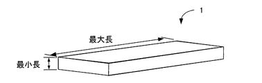
- FIG. 1 and FIG. 2A show an embodiment of the porous plate filler 1 of the present invention.
- FIG. 1 is a schematic view showing an embodiment of a porous plate-like filler 1.
- FIG. 2A is a figure which shows the cross section of the porous plate-shaped filler 1, and its expansion.
- the porous plate-like filler 1 has a plate shape with an aspect ratio of 3 or more, a minimum length of 0.1 to 50 ⁇ m, and a porosity of 20 to 90%.
- the porous plate-like filler 1 has plate-like pores 2 having an aspect ratio of 1.5 or more.
- the porous plate filler 1 preferably has pores 2 having a pore diameter of 10 to 500 nm.
- the porosity of the porous plate filler 1 is preferably 20 to 90%, more preferably 40 to 85%, and still more preferably 50 to 80%. By setting the porosity to 90% or less, the strength can be ensured. Moreover, thermal conductivity can be reduced by making a porosity into 20% or more.
- the aspect ratio of the porous plate-like filler 1 is defined by the maximum length / minimum length of the porous plate-like filler 1.
- the maximum length is the maximum length when the particles (porous plate filler 1) are sandwiched between a pair of parallel surfaces.
- the minimum length is the minimum length when the particles are sandwiched between a pair of parallel surfaces, and corresponds to a so-called thickness in the case of a flat plate shape.
- the plate shape of the porous plate filler 1 is not only flat plate (flat and uncurved plate) but also curved if the aspect ratio is 3 or more and the minimum length is 0.1 to 50 ⁇ m. And a plate-like material whose thickness (minimum length) is not constant are also included.
- the shape may be a fiber shape, a needle shape, a lump shape, or the like.
- the porous plate-like filler 1 has a flat plate shape.
- the surface shape of the plate may be any shape such as a square, a square, a triangle, a hexagon, and a circle. That is, the porous plate-like filler 1 may have any shape as long as it is plate-like.
- the aspect ratio of the porous plate filler 1 is preferably 3 or more.
- the aspect ratio is more preferably 3 to 50, further preferably 3.5 to 40, and most preferably 4 to 30.
- the aspect ratio of the pores 2 of the porous plate filler 1 is defined by the maximum length / minimum length of the pores 2.
- the maximum length of the pores 2 is the maximum length in the cross section in the direction of the minimum length of the porous plate filler 1. After the maximum length of the pore 2 is determined, a line perpendicular thereto is drawn, and the length of the vertical line is defined as the minimum length of the pore 2.
- the average aspect ratio is 1.5 or more, preferably Is 3 or more.
- the thermal conductivity of the porous plate-like filler 1 in the direction crossing the pores 2 is lowered. If the thermal conductivity of the porous plate-like filler 1 is lowered, the heat insulating effect of the heat insulating film 3 including this can be improved, and when the heat insulating film 3 is formed, the thickness of the heat insulating film 3 can be reduced. As a result, the effect of increasing the space can be expected, and the cost can be reduced. Moreover, when joining the heat insulation film
- the surface shape may be any shape such as a square, a quadrangle, a triangle, a hexagon, and a circle. That is, the shape of the pores 2 is not particularly limited as long as it is a plate shape having an aspect ratio of 1.5 or more. Further, the aspect ratio of the pores 2 is approximately the same as the aspect ratio of the pore former. That is, since the shape of the pores 2 is determined by the shape of the pore former, it is preferable to use a plate-shaped material having an aspect ratio of 1.5 or more, preferably 3 or more.
- the material for the pore former is not particularly limited as long as it is in the above form, and graphite, latex, melamine resin, PMMA, polyethylene, polystyrene, carbon black, foamed resin, water absorbent resin, and the like can be used.
- FIG. 2A shows the porous plate-like filler 1, and also shows an enlarged view of a part thereof.
- the average of the angle k between the minimum length direction of the pores 2 and the minimum length direction of the porous plate filler 1 in the cross section in the minimum length direction of the porous plate filler 1 is preferably 45 ° or less, The angle is more preferably 30 ° or less, and further preferably 10 ° or less.
- Examples of the material for the porous plate filler 1 include hollow plate glass and hollow plate ceramics.
- examples include mesoporous silica, mesoporous titania, mesoporous zirconia, and shirasu balloon.
- the porous plate-shaped filler obtained with the manufacturing method mentioned later is also mentioned.
- the porous plate-like filler 1 preferably contains a metal oxide, and more preferably consists only of a metal oxide. This is because when the metal oxide is included, the thermal conductivity tends to be low because the ionic bond between the metal and oxygen is stronger than the metal non-oxide (for example, carbide or nitride).
- a metal oxide for example, carbide or nitride
- the porous plate-like filler 1 is selected from the group consisting of metal oxides Zr, Y, Al, Si, Ti, Nb, Sr, La, Hf, Ce, Gd, Sm, Mn, Yb, Er, and Ta. It is preferably an oxide of one element or a composite oxide of two or more elements. This is because when the metal oxide is an oxide or complex oxide of these elements, heat conduction due to lattice vibration (phonon), which is a main cause of heat conduction, is less likely to occur.
- Specific materials for the porous plate-like filler 1 include those obtained by adding Gd 2 O 3 , Yb 2 O 3 , Er 2 O 3 or the like to ZrO 2 —Y 2 O 3 .
- the porous plate-like filler 1 may be an inorganic material, an organic material, or a composite material of an inorganic material and an organic material.
- zirconia partially stabilized zirconia (for example, yttria partially stabilized zirconia), fully stabilized zirconia (for example, yttria fully stabilized zirconia), yttrium oxide, alumina, silica, titania, niobium oxide, strontium oxide, lanthanum oxide, Zirconium, yttria, aluminum, silicon, titanium, niobium, strontium, lanthanum, rare earth zirconate (eg lanthanum zirconate), rare earth silicate (eg yttrium silicate), niobate (eg strontium niobate), It is preferably an inorganic material such as mullite, mica, spinel, zircon, magnesia, ceria, silicon carbide, silicon n
- the porous plate-like filler 1 is preferably configured to include particles having a particle size of 1 nm to 10 ⁇ m.
- the particle may be a particle (single crystal particle) made of one crystal grain or a particle (polycrystalline particle) made of a large number of crystal grains. That is, the porous plate-like filler 1 is preferably a collection of particles having a particle size in this range.
- the particle size the size of one particle in the particle group constituting the skeleton of the porous plate-like filler 1 (diameter if spherical, maximum diameter otherwise) was measured from an electron microscope image. Is.
- the particle size is more preferably 1 nm to 5 ⁇ m, and still more preferably 50 nm to 1 ⁇ m. When the porous plate-like filler 1 having a particle size in such a range is included in the heat insulating film 3, the heat insulating effect can be improved.
- the minimum length of the porous plate filler 1 is 0.1 to 50 ⁇ m, more preferably 0.5 to 20 ⁇ m, still more preferably 2 to 15 ⁇ m, and most preferably 2 to 10 ⁇ m. If the minimum length of the porous plate-like filler 1 is shorter than 0.1 ⁇ m, it may be difficult to maintain the shape of the porous plate-like filler 1 during the manufacturing process. If the minimum length of the porous plate-like filler 1 is longer than 50 ⁇ m, the number of layers of the porous plate-like filler 1 is reduced when the porous plate-like filler 1 is included in the heat insulating film 3, so that the heat transfer path is shortened by being close to a straight line, The heat conductivity of the heat insulation film 3 may become high. Moreover, when the minimum length of the porous plate-like filler 1 is short, the heat insulating film 3 can be made thin. That is, even if it is the thin heat insulation film 3, the heat insulation effect can be improved.
- the porous plate-like filler 1 preferably has a thermal conductivity of 1 W / (m ⁇ K) or less.
- the thermal conductivity is more preferably 0.7 W / (m ⁇ K) or less, further preferably 0.5 W / (m ⁇ K) or less, and most preferably 0.3 W / (m ⁇ K) or less.
- the porous plate-like filler 1 having such a thermal conductivity is included in the heat insulating film 3, the heat insulating effect can be improved.
- thermal diffusivity is measured by the optical alternating current method.
- Specific heat is measured by DSC method.
- Density is measured with a mercury porosimeter.
- the porous plate-like filler 1 preferably has a heat capacity of 10 to 3000 kJ / (m 3 ⁇ K).
- the heat capacity is more preferably 10 to 2500 kJ / (m 3 ⁇ K), further preferably 300 to 2000 kJ / (m 3 ⁇ K), and most preferably 400 to 1500 kJ / (m 3 ⁇ K).
- the porous plate-like filler 1 having a heat capacity in such a range is included in the heat insulating film 3, the heat insulating effect can be improved.
- the heat capacity is generally discussed per unit volume called volume specific heat, the unit is kJ / (m 3 ⁇ K).
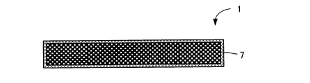
- the porous plate-like filler 1 preferably has a coating layer 7 having a thickness of 1 nm to 1 ⁇ m on at least a part of the surface.
- the coating layer 7 is preferably a heat resistance film that suppresses heat transfer and / or reflects radiant heat and / or scatters lattice vibrations (phonons). It is preferable to form a thermal resistance film of several tens of nm on the surface of the porous plate filler 1 because the thermal conductivity of the heat insulating film 3 can be further lowered.
- the heat resistance film is not required to be the same material as the porous plate-like filler to be coated, and it is desirable to coat the porous plate-like filler 1 with a different material (for example, alumina, zinc oxide).
- a different material for example, alumina, zinc oxide.
- the heat resistance film is dense or porous, but it is preferably dense.
- the heat resistance film is formed on a part of the surface of the porous plate-like filler 1, the effect of lowering the thermal conductivity can be obtained. However, the entire surface of the porous plate-like filler 1 becomes the heat resistance film. If it is covered, the effect of lowering the thermal conductivity can be obtained.
- a method for producing the porous plate filler 1 will be described.
- a slurry containing a plate-like pore former having an aspect ratio of 1.5 or more is prepared, and the aspect ratio is 1.5 by firing the pore former.
- This is a method for producing the porous plate-like filler 1 having the plate-like pores 2 described above.
- Examples of the method for producing the porous plate-like filler 1 include press molding, cast molding, extrusion molding, injection molding, tape molding, doctor blade method, and the like. Will be described as an example.
- a slurry for forming a green sheet is prepared by adding a pore former, a binder, a plasticizer, a solvent and the like to the ceramic powder and mixing them with a ball mill or the like.
- Ceramic powders include zirconia powder, partially stabilized zirconia powder (eg, yttria partially stabilized zirconia powder), fully stabilized zirconia powder (eg, yttria fully stabilized zirconia powder), alumina powder, silica powder, titania powder, oxidation Lanthanum powder, yttria powder, rare earth zirconate powder (eg lanthanum zirconate powder), rare earth silicate powder (eg yttrium silicate powder), niobate powder (eg strontium niobate powder), mullite powder, spinel Powder, zircon particles, magnesia powder, yttria powder, ceria powder, silicon carbide powder, silicon nitride powder, aluminum nitride powder, and the like can be used. These may be used alone or in combination of two or more. Further, the powder is not limited to a dry powder, and a powder in a colloidal state (sol state) dispersed in
- pore former graphite, latex, melamine resin, PMMA, polyethylene, polystyrene, carbon black, foamed resin, water absorbent resin and the like can be used.
- binder polyvinyl butyral resin (PVB), polyvinyl alcohol resin / polyvinyl acetate resin / polyacrylic resin, or the like can be used.
- plasticizer DBP (dibutyl phthalate), DOP (dioctyl phthalate), or the like can be used.
- solvent xylene, 1-butanol and the like can be used.
- the above green sheet forming slurry is vacuum defoamed to adjust to 100 to 90000 cps, more preferably 700 to 50000 cps.
- the angle of the pore 2 is determined by the arrangement of the pore former in the molded body (formed from a green sheet into a predetermined shape). The lower the viscosity of the green sheet molding slurry, the easier it is for the pore former to move during molding and to align the direction. By setting the viscosity to 100 cps or more, the shape can be maintained as a molded body. It can be formed into a desired shape by having a viscosity of 90000 cps or less. Accordingly, in order to make the pores 2 have a desired angle, it is preferable that the viscosity of the green sheet forming slurry is within the above range.
- a green sheet is formed from the green sheet forming slurry by a doctor blade device so that the thickness after firing is 0.1 to 100 ⁇ m.
- the thickness of the green sheet is preferably 70 ⁇ m or less, more preferably 50 ⁇ m or less, and even more preferably 30 ⁇ m or less.
- the outer shape is cut to a size of (0.5 to 200) mm ⁇ (0.5 to 200) mm. The cut molded body is fired at 800 to 2300 ° C.
- porous thin plate filler 1 porous plate filler 1
- processing such as cutting or punching into a predetermined surface shape (square, quadrilateral, hexagonal, circular), etc. in the state of the green sheet before firing, firing it, and without pulverizing after firing, it is porous
- a thin plate filler can also be obtained.
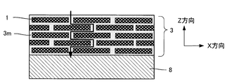
- thermal insulation film 3 is demonstrated using FIG.
- the above-mentioned porous plate-like filler 1 is dispersed and arranged in a matrix 3 m for bonding the porous plate-like filler 1.
- the matrix 3m is a component that exists around the porous plate-like filler 1 and between these particles, and is a component that binds between these particles.
- the porous plate-like filler 1 is preferably arranged (laminated) in layers.
- the term “layered arrangement” as used herein refers to a matrix in which a number of porous plate-like fillers 1 are oriented in a direction in which the minimum length of the porous plate-like filler 1 is nearly parallel to the thickness direction of the heat insulating film 3. It says that it exists in 3m.
- the position (position of the center of gravity) of the porous plate filler 1 is regularly and periodically arranged in the X, Y, and Z directions of the heat insulating film 3 (where the Z direction is the thickness (film thickness) direction).
- the matrix 3m portion having a high thermal conductivity is the main heat transfer path, but the heat insulating film 3 of the present invention includes the porous plate-like filler 1, and the heat transfer path transfers heat.
- the direction (thickness direction) that you do not want. That is, since the length of the heat transfer path is increased, the thermal conductivity can be lowered. Further, since the bonding area between the porous plate-like fillers 1 through the matrix 3m is wider than that of the spherical filler, the strength of the entire heat insulating film is increased, and erosion and peeling are less likely to occur.
- the porous plate-like filler 1 is plate-like, it is difficult to form irregularities on the outermost surface of the heat insulating film 3 as compared with the case of a spherical filler. Therefore, even when an impact is applied to the heat insulating film portion, it is possible to prevent the porous plate-like filler 1 from dropping, that is, the heat insulating film 3 from being lost.
- the heat insulating film 3 of the present invention preferably contains at least one of ceramics, glass, and resin as the matrix 3m.
- ceramics or glass is more preferable.
- the material for forming the matrix 3m include silica, alumina, mullite, zirconia, titania, silicon nitride, silicon oxynitride, silicon carbide, silicon oxycarbide, calcium silicate, calcium aluminate, and calcium aluminosilicate.
- the material of the matrix 3m is ceramics, it is desirable to be an aggregate of fine particles having a particle size of 500 nm or less. By making an aggregate of fine particles having a particle size of 500 nm or less into the matrix 3 m, the thermal conductivity can be further reduced.
- the material used as the matrix 3m is resin, a silicone resin, a polyimide resin, a polyamide resin, an acrylic resin, an epoxy resin, etc. can be mentioned.
- the heat insulating film 3 has a total porosity of 10 to 90% of the heat insulating film 3, a porosity of the porous plate filler 1 of 20 to 90%, and a porosity of the matrix 3m of 0 to 70%. Preferably there is.
- the heat insulating film 3 of the present invention preferably has a thickness of 1 ⁇ m to 5 mm. By setting it as such thickness, the heat insulation effect can be acquired, without having a bad influence on the characteristic of the base material 8 coat
- FIG. The thickness of the heat insulating film 3 can be appropriately selected within the above range depending on the application.
- Insulation film 3 of the present invention preferably has a heat capacity is 1500kJ / (m 3 ⁇ K) or less, more preferably 1300kJ / (m 3 ⁇ K) or less, 1000kJ / (m 3 ⁇ K ) or less It is more preferable that it is 500 kJ / (m 3 ⁇ K) or less. If the heat capacity is low, for example, when the heat insulating film 3 is formed in the engine combustion chamber, the temperature of the heat insulating film 3 tends to cool after the fuel is exhausted. Thereby, problems such as abnormal combustion of the engine can be suppressed.
- the heat insulating film 3 of the present invention preferably has a thermal conductivity in the thickness direction of 1.5 W / (m ⁇ K) or less.
- the heat insulating film 3 is more preferably 1 W / (m ⁇ K) or less, and most preferably 0.5 W / (m ⁇ K) or less. Heat transfer can be suppressed by having low thermal conductivity.
- a method for manufacturing the heat insulating film 3 will be described.
- a coating composition containing the above-mentioned porous plate-like filler 1 and at least one selected from the group consisting of an inorganic binder, an inorganic polymer, an organic-inorganic hybrid material, an oxide sol, and water glass is prepared.
- the coating composition may further contain a dense filler, a viscosity modifier, a solvent, a dispersant and the like.
- the heat insulation film 3 can be formed by applying, drying and / or heat-treating the coating composition.
- Specific materials included in the coating composition include cement, bentonite, aluminum phosphate, silica sol, alumina sol, boehmite sol, zirconia sol, titania sol, tetramethyl orthosilicate, tetraethyl orthosilicate, polysilazane, polycarbosilane, polyvinyl silane, Polymethylsilane, polysiloxane, polysilsesquioxane, silicone, geopolymer, sodium silicate and the like.
- acrylic-silica hybrid materials acrylic-silica hybrid materials, epoxy-silica hybrid materials, phenol-silica hybrid materials, polycarbonate-silica hybrid materials, nylon-silica hybrid materials, nylon-clay hybrid materials
- acrylic-alumina hybrid material an acrylic-calcium silicate hydrate hybrid material, and the like are desirable.
- the solvent examples include, but are not limited to, ethanol and 2-propanol.
- the dispersant is not particularly limited, but anions such as alkylol ammonium salt, soap (fatty acid sodium salt), monoalkyl sulfate, alkyl polyoxyethylene sulfate, alkylbenzene sulfonate, monoalkyl phosphate, etc.
- Cationic properties such as alkyltrimethylammonium salt, dialkyldimethylammonium salt, alkylbenzyldimethylammonium salt, duality such as alkyldimethylamine oxide, alkylcarboxybetaine, polyoxyethylene alkyl ether, fatty acid sorbitan ester, alkylpolyglucoside, fatty acid Nonionic ones such as diethanolamide and alkyl monoglyceryl ether can be mentioned.
- a dispersant so as to be 0.04 to 3 parts by mass with respect to 100 parts by mass of the porous plate-like filler 1, the porous plate-like filler 1 can be easily dispersed uniformly in the coating composition.
- the viscosity of the coating composition is preferably 0.1 to 5000 cps, more preferably 0.5 to 1000 cps. If the viscosity is less than 0.1 cps, the film may flow after coating and the coating thickness may become non-uniform. If it is greater than 5000 cps, there is no fluidity and it may be difficult to apply uniformly.
- the heat insulating film 3 in which the porous plate-like filler 1 is uniformly dispersed in the matrix 3 m can be obtained.
- the viscosity is too high, the porous plate-like filler 1 is difficult to uniformly disperse, and a portion where the porous plate-like filler 1 is reduced inside the heat insulating film 3 tends to occur.
- the dispersant By adding the dispersant, the dispersibility of the porous plate-like filler 1 in the coating composition (slurry) can be improved, and a homogeneous heat insulating film 3 can be made. That is, by improving the dispersibility of the porous plate-like filler 1, it is possible to obtain a homogeneous heat insulating film 3 and to reduce the thermal conductivity.
- the heat insulating film 3 can be formed by applying the coating composition described above on the substrate 8 and drying it. It can also be formed by heat treatment after drying. At this time, the thick heat insulating film 3 can be formed by repeating application and drying or heat treatment. Alternatively, after the heat insulating film 3 is formed on the temporary base material, the temporary base material is removed to separately produce the heat insulating film 3 formed in a thin plate shape alone.
- the material 8 may be bonded or bonded.
- metal, ceramics, glass, plastic, wood, cloth, paper, or the like can be used. In particular, examples where the substrate 8 is a metal include iron, iron alloy, stainless steel, aluminum, aluminum alloy, nickel alloy, cobalt alloy, tungsten alloy, and copper alloy.
- the heat insulating film 3 of the present invention can be used for engine combustion chambers, piping, cooking utensils, building materials and the like.
- Example 1 First, yttria partially stabilized zirconia powder, pore former (plate-like graphite: SEC carbon SGP-3), polyvinyl butyral resin (PVB) as a binder, DOP as a plasticizer, xylene and 1-butanol as a solvent And mixed for 30 hours in a ball mill to prepare a green sheet forming slurry.
- the slurry was subjected to vacuum defoaming treatment to adjust the viscosity to 20000 cps, and then a green sheet was formed and pulverized with a doctor blade device so that the thickness after firing was 10 ⁇ m to obtain a thin plate molded body. .
- This molded body was fired at 1100 ° C. for 1 hour to obtain a porous thin plate filler (porous plate filler 1).
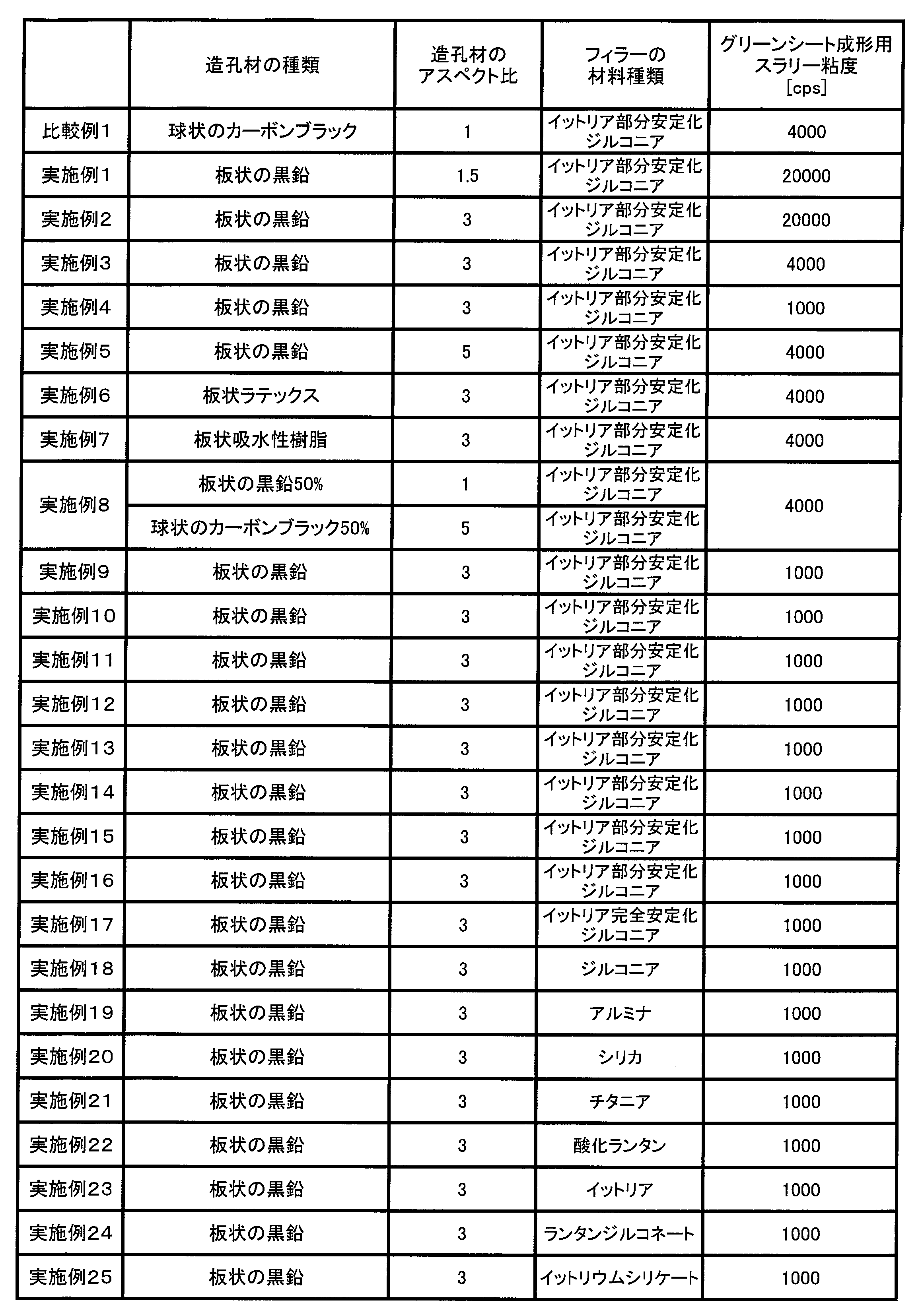
- Example 2 In the same manner as in Example 1, a porous plate filler 1 was obtained. Table 1 shows the type of pore former used, the aspect ratio, and the viscosity of the green sheet forming slurry. In Example 8, 50 vol% of the amount of the pore former added was graphite, and 50 vol% was carbon black.
- Example 9 In the same manner as in Example 1, a porous plate filler 1 was obtained.
- Table 1 shows the type of pore former used, the aspect ratio, and the viscosity of the green sheet forming slurry.
- the green sheet was shape
- Example 17 A porous plate-like filler 1 having a material different from that of Example 1 was produced.
- the material of the porous plate filler 1 is shown in Table 1.
- the porous plate-like fillers 1 of Examples 1 to 8 and Comparative Example 1 include pores 2 having an average aspect ratio of 4 for any 20 and a pore diameter of 150 nm, and a thickness (minimum length) of 10 ⁇ m. Met.
- the porosity was 60%.
- the porous plate fillers 1 of Examples 9 to 25 had the aspect ratio, pore diameter, minimum length, and porosity shown in Table 2.
- FIG. A circle is a pore 2 formed by a pore former. 50 shapes of the pores 2 in the filler were observed, and the minimum length and the maximum length were measured. The maximum length / minimum length was defined as the aspect ratio, and the average was obtained.
- Table 2 shows A when the average aspect ratio of the pores 2 is 1.5 or more, and B when it is not. Table 2 shows the case where the average aspect ratio of the pores 2 is 3 or more as A, and the case where the average aspect ratio is not B as B.
- the minimum length of the pores 2 was in the same direction as the minimum length of the porous plate filler 1. 50 pores 2 were selected at random, and an angle k (see FIG. 2A) between the minimum length direction of the pores 2 and the minimum length direction of the porous plate-like filler 1 was measured, and the average was obtained.
- a porous plate-like filler 1 having a minimum length direction of 0.5 mm and a diameter of 10 mm was separately prepared, and the thermal conductivity in the minimum length direction of the porous plate-like filler 1 was measured with a laser flash.
- the heat capacity of the porous plate filler 1 was calculated as follows. The specific heat was measured by the DSC method, and the product of specific heat and density (apparent particle density) was defined as the heat capacity of the porous plate filler 1. The apparent particle density was measured by an immersion method using mercury.
- the porous plate-like filler 1 having plate-like pores 2 having an aspect ratio of 1.5 or more has a low thermal conductivity
- the heat insulating film 3 including the porous plate-like filler 1 has a low thermal conductivity.
- yttria partially stabilized zirconia (Examples 1 to 16), yttria fully stabilized zirconia (Example 17), and zirconia (Example 18), which are zirconia, particularly thermal conductivity could be lowered.
- the metal oxide since the metal oxide has strong ion bonding between the metal and oxygen, the metal oxides of alumina (Example 19), silica (Example 20), titania (Example 21), lanthanum oxide (implementation) Example 22) and yttria (Example 23) were also able to reduce the thermal conductivity.
- Lanthanum zirconate (Example 24) and yttrium silicate (Example 25) also gave good results.
- the method for producing a porous plate filler, a heat insulating film, and a porous plate filler of the present invention can be applied to engines such as automobiles, piping, building materials, cooking utensils, and the like.
Landscapes
- Chemical & Material Sciences (AREA)
- Organic Chemistry (AREA)
- Engineering & Computer Science (AREA)
- Materials Engineering (AREA)
- Ceramic Engineering (AREA)
- Life Sciences & Earth Sciences (AREA)
- Wood Science & Technology (AREA)
- Structural Engineering (AREA)
- General Engineering & Computer Science (AREA)
- Inorganic Chemistry (AREA)
- Chemical Kinetics & Catalysis (AREA)
- Mechanical Engineering (AREA)
- Porous Artificial Stone Or Porous Ceramic Products (AREA)
- Compositions Of Macromolecular Compounds (AREA)
- Paints Or Removers (AREA)
- Manufacture Of Porous Articles, And Recovery And Treatment Of Waste Products (AREA)
- Thermal Insulation (AREA)
- Laminated Bodies (AREA)
Abstract
Description
図1、及び図2Aに本発明の多孔質板状フィラー1の一実施形態を示す。図1は、多孔質板状フィラー1の一実施形態を示す模式図である。また、図2Aは、多孔質板状フィラー1の断面と、その拡大を示す図である。多孔質板状フィラー1は、アスペクト比が3以上の板状で、その最小長が0.1~50μm、気孔率が20~90%である。また、多孔質板状フィラー1は、アスペクト比が1.5以上の板状の気孔2を有する。
気孔率(%)=(1-(見かけ粒子密度/真密度))×100
上記の式において、見かけ粒子密度は、水銀を用いた液浸法により測定する。また、真密度は、多孔質板状フィラー1を十分に粉砕した後、ピクノメータ法で測定する。
熱伝導率(W/(m・K))=熱拡散率×比熱×密度
この式において、「熱拡散率」は、光交流法により測定する。また、「比熱」は、DSC法により測定する。「密度」は、水銀ポロシメーターで測定する。
熱容量(kJ/(m3・K))=比熱×密度(見かけ粒子密度)
この式において、「比熱」は、DSC法により測定する。また、「密度(見かけ粒子密度)」は、水銀を用いた液浸法により測定する。
次に、多孔質板状フィラー1の製造方法について説明する。本発明の多孔質板状フィラー1の製造方法は、アスペクト比が1.5以上の板状の造孔材を含むスラリーを調製し、造孔材を焼成することにより、アスペクト比が1.5以上の板状の気孔2を有する多孔質板状フィラー1を製造する方法である。多孔質板状フィラー1の製造方法としては、プレス成形、鋳込み成形、押出成形、射出成形、テープ成形、ドクターブレード法等が挙げられ、いずれの方法であってもよいが、以下、ドクターブレード法を例として説明する。
図3を用いて、断熱膜3を説明する。本発明の断熱膜3は、上述の多孔質板状フィラー1が、多孔質板状フィラー1を結合するためのマトリックス3mに分散して配置されている。マトリックス3mとは、多孔質板状フィラー1の周囲やこれらの粒子間に存在する成分であり、これらの粒子間を結合する成分である。
(実施例1)
まず、イットリア部分安定化ジルコニア粉末に、造孔材(板状の黒鉛:SECカーボン SGP-3)、バインダーとしてのポリビニルブチラール樹脂(PVB)、可塑剤としてのDOP、溶剤としてのキシレンおよび1-ブタノールを加え、ボールミルにて30時間混合し、グリーンシート成形用スラリーを調製した。このスラリーに真空脱泡処理を施すことにより、粘度を20000cpsに調整した後、ドクターブレード装置によって焼成後の厚さが10μmとなるようにグリーンシートを形成、粉砕して薄板の成形体を得た。この成形体を1100℃、1時間にて焼成して、多孔質な薄板状フィラー(多孔質板状フィラー1)を得た。
実施例1と同様にして多孔質板状フィラー1を得た。使用した造孔材の種類、アスペクト比、グリーンシート成形用スラリーの粘度を表1に示す。なお、実施例8は、造孔材を添加する量の50vol%を黒鉛、50vol%をカーボンブラックとした。
実施例1と同様にして多孔質板状フィラー1を得た。使用した造孔材の種類、アスペクト比、グリーンシート成形用スラリーの粘度を表1に示す。なお、焼成後の多孔質板状フィラー1の厚さとアスペクト比が表2に示す値になるようにグリーンシートを成形し、粉砕した。
実施例1と材料が異なる多孔質板状フィラー1を作製した。多孔質板状フィラー1の材料については、表1に示す。
実施例と同様にして多孔質板状フィラー1を得た。造孔材は、球状のカーボンブラックを用いた。
気孔率(%)=(1-(見かけ粒子密度/真密度))×100
上記の式において、見かけ粒子密度は、水銀を用いた液浸法により測定した。また、真密度は、多孔質板状フィラー1を十分に粉砕した後、ピクノメータ法で測定した。実施例9~25の多孔質板状フィラー1は、表2に示すアスペクト比、気孔径、最小長、気孔率であった。
フィラーを無作為に1個選び、FE-SEMにて微構造観察を行った。図4Aに実施例1、図4Bに比較例1の多孔質板状フィラー1の最小長方向のFE-SEM写真を示す。丸が造孔材によって形成された気孔2である。フィラー内にある気孔2の形状を50個観察し、最小長、最大長を測定した。最大長/最小長をアスペクト比と定義し、その平均を求めた。気孔2の平均のアスペクト比が1.5以上の場合をA、そうでない場合をBとして、表2に示す。また、気孔2の平均のアスペクト比が3以上の場合をA、そうでない場合をBとして、表2に示す。また気孔2の最小長が多孔質板状フィラー1の最小長と同じ方向であるか確認した。気孔2を無作為に50個選び、気孔2の最小長の方向と多孔質板状フィラー1の最小長の方向との角度k(図2A参照)を測定し、その平均を求めた。
最小長方向が0.5mm、直径10mmの多孔質板状フィラー1を別途作製し、レーザーフラッシュにて多孔質板状フィラー1の最小長方向の熱伝導率を測定した。
多孔質板状フィラー1の熱容量は、以下のようにして算出した。DSC法により比熱を測定し、比熱、密度(見かけ粒子密度)の積を多孔質板状フィラー1の熱容量とした。見かけ粒子密度は、水銀を用いた液浸法により測定した。
(実施例1~25、比較例1)
次に、マトリックス3mとなるポリシロキサン、多孔質板状フィラー1、水を含むコーティング組成物を調製した。なお、コーティング組成物には、分散剤を添加した。基材であるSUS基板(直径10mm、厚さ1mm)上に塗布し、乾燥後、200℃の熱処理により、断熱膜3とした。断熱膜3は多孔質板状フィラー1が厚さ方向に5枚以上積層されており、その厚さはおよそ100μmであった。
レーザーフラッシュ2層モデルにて断熱膜3の厚さ方向に平行な断面における熱伝導率を測定した。

Claims (7)
- アスペクト比が3以上の板状で、その最小長が0.1~50μm、気孔率が20~90%であるとともに、
アスペクト比が1.5以上の板状の気孔を有する多孔質板状フィラー。 - 前記多孔質板状フィラーの最小長の方向の断面における、前記気孔の最小長の方向と前記多孔質板状フィラーの最小長の方向との角度の平均が45°以下である請求項1に記載の多孔質板状フィラー。
- 前記多孔質板状フィラーの最小長の方向の熱伝導率が1W/(m・K)以下である請求項1または2に記載の多孔質板状フィラー。
- 請求項1~3のいずれか1項に記載の多孔質板状フィラーを含む断熱膜。
- 厚さ方向における熱伝導率が1.5W/(m・K)以下である請求項4に記載の断熱膜。
- 請求項1~3のいずれか1項に記載の多孔質板状フィラーの製造方法であって、アスペクト比が1.5以上の板状の造孔材を含むスラリーを調製し、前記造孔材を焼成することにより、アスペクト比が1.5以上の板状の前記気孔を有する多孔質板状フィラーを製造する多孔質板状フィラーの製造方法。
- 前記スラリーの粘度が、100~90000cpsである請求項6に記載の多孔質板状フィラーの製造方法。
Priority Applications (3)
| Application Number | Priority Date | Filing Date | Title |
|---|---|---|---|
| JP2016513770A JP6527139B2 (ja) | 2014-04-17 | 2015-04-13 | 多孔質板状フィラー、断熱膜、及び多孔質板状フィラーの製造方法 |
| EP15779615.2A EP3133052B1 (en) | 2014-04-17 | 2015-04-13 | Porous plate-like filler, heat insulation film and method for producing porous plate-like filler |
| US15/284,798 US10317004B2 (en) | 2014-04-17 | 2016-10-04 | Porous plate-shaped filler, heat insulation film, and method for producing porous plate-shaped filler |
Applications Claiming Priority (2)
| Application Number | Priority Date | Filing Date | Title |
|---|---|---|---|
| JP2014085911 | 2014-04-17 | ||
| JP2014-085911 | 2014-04-17 |
Related Child Applications (1)
| Application Number | Title | Priority Date | Filing Date |
|---|---|---|---|
| US15/284,798 Continuation US10317004B2 (en) | 2014-04-17 | 2016-10-04 | Porous plate-shaped filler, heat insulation film, and method for producing porous plate-shaped filler |
Publications (1)
| Publication Number | Publication Date |
|---|---|
| WO2015159838A1 true WO2015159838A1 (ja) | 2015-10-22 |
Family
ID=54324044
Family Applications (1)
| Application Number | Title | Priority Date | Filing Date |
|---|---|---|---|
| PCT/JP2015/061319 Ceased WO2015159838A1 (ja) | 2014-04-17 | 2015-04-13 | 多孔質板状フィラー、断熱膜、及び多孔質板状フィラーの製造方法 |
Country Status (4)
| Country | Link |
|---|---|
| US (1) | US10317004B2 (ja) |
| EP (1) | EP3133052B1 (ja) |
| JP (1) | JP6527139B2 (ja) |
| WO (1) | WO2015159838A1 (ja) |
Cited By (2)
| Publication number | Priority date | Publication date | Assignee | Title |
|---|---|---|---|---|
| JP2021048069A (ja) * | 2019-09-19 | 2021-03-25 | イビデン株式会社 | 組電池用断熱シート及び組電池 |
| CN117567878A (zh) * | 2024-01-11 | 2024-02-20 | 中稀易涂科技发展有限公司 | 一种高性能多孔辐射制冷填料及其制备方法 |
Families Citing this family (7)
| Publication number | Priority date | Publication date | Assignee | Title |
|---|---|---|---|---|
| US10781319B2 (en) * | 2011-01-21 | 2020-09-22 | Lockheed Martin Corporation | Ultra high temperature environmental protection coating |
| WO2019239178A1 (ja) * | 2018-06-13 | 2019-12-19 | 日産自動車株式会社 | 遮熱部材 |
| US11426818B2 (en) | 2018-08-10 | 2022-08-30 | The Research Foundation for the State University | Additive manufacturing processes and additively manufactured products |
| CN114375228B (zh) * | 2019-11-26 | 2024-06-28 | Fl史密斯公司 | 用于粉碎装置的耐磨元件 |
| DE102020129161A1 (de) * | 2020-11-05 | 2022-05-05 | Schott Ag | Glas- oder Glaskeramikelement umfassend Glas- oder Glaskeramiksubstrat und Beschichtung sowie Verfahren zu dessen Herstellung und dessen Verwendung |
| CN113097228B (zh) * | 2021-03-24 | 2023-10-03 | 深圳市华星光电半导体显示技术有限公司 | 遮光基板及其制备方法和阵列基板 |
| CN117922815B (zh) * | 2024-01-25 | 2025-09-16 | 中国航空制造技术研究院 | 面内可变形的热防护结构 |
Citations (3)
| Publication number | Priority date | Publication date | Assignee | Title |
|---|---|---|---|---|
| JP2005263537A (ja) * | 2004-03-17 | 2005-09-29 | Rikogaku Shinkokai | 貫通孔を有するセラミックス多孔体の製造方法 |
| JP2009274895A (ja) * | 2008-05-13 | 2009-11-26 | Daimu:Kk | 扁平状の連続気孔が積層配向されたセラミックス焼結体とその製造方法 |
| WO2013191263A1 (ja) * | 2012-06-20 | 2013-12-27 | 日本碍子株式会社 | 多孔質板状フィラー、コーティング組成物、断熱膜、および断熱膜構造 |
Family Cites Families (5)
| Publication number | Priority date | Publication date | Assignee | Title |
|---|---|---|---|---|
| EP1769049A2 (en) * | 2004-07-16 | 2007-04-04 | Ciba Specialty Chemicals Holding Inc. | Luminescent silicon oxide flakes |
| GB0516968D0 (en) * | 2005-08-18 | 2005-09-28 | Dunwilco 1198 Ltd | Process |
| JP4925086B2 (ja) * | 2005-10-21 | 2012-04-25 | 独立行政法人産業技術総合研究所 | 薄板状もしくは繊維状の有機無機多孔質シリカ粒子とその製造方法 |
| US8713693B2 (en) * | 2011-07-26 | 2014-04-29 | Salesforce.Com, Inc. | Secure access to customer log data in a multi-tenant environment |
| WO2013125713A1 (ja) * | 2012-02-24 | 2013-08-29 | 日本碍子株式会社 | ハニカム構造体 |
-
2015
- 2015-04-13 JP JP2016513770A patent/JP6527139B2/ja active Active
- 2015-04-13 WO PCT/JP2015/061319 patent/WO2015159838A1/ja not_active Ceased
- 2015-04-13 EP EP15779615.2A patent/EP3133052B1/en active Active
-
2016
- 2016-10-04 US US15/284,798 patent/US10317004B2/en not_active Expired - Fee Related
Patent Citations (3)
| Publication number | Priority date | Publication date | Assignee | Title |
|---|---|---|---|---|
| JP2005263537A (ja) * | 2004-03-17 | 2005-09-29 | Rikogaku Shinkokai | 貫通孔を有するセラミックス多孔体の製造方法 |
| JP2009274895A (ja) * | 2008-05-13 | 2009-11-26 | Daimu:Kk | 扁平状の連続気孔が積層配向されたセラミックス焼結体とその製造方法 |
| WO2013191263A1 (ja) * | 2012-06-20 | 2013-12-27 | 日本碍子株式会社 | 多孔質板状フィラー、コーティング組成物、断熱膜、および断熱膜構造 |
Non-Patent Citations (2)
| Title |
|---|
| S.GAYDARDZHIEV ET AL.: "Gel-casted porous A1203 ceramics by use of natural fibres as pore developers", JOURNAL OF POROUS MATERIALS, vol. 15, no. Issue 4, 2008, pages 475 - 480, XP019609400, ISSN: 1380-2224 * |
| See also references of EP3133052A4 * |
Cited By (6)
| Publication number | Priority date | Publication date | Assignee | Title |
|---|---|---|---|---|
| JP2021048069A (ja) * | 2019-09-19 | 2021-03-25 | イビデン株式会社 | 組電池用断熱シート及び組電池 |
| WO2021054110A1 (ja) * | 2019-09-19 | 2021-03-25 | イビデン株式会社 | 組電池用断熱シート及び組電池 |
| CN114424386A (zh) * | 2019-09-19 | 2022-04-29 | 揖斐电株式会社 | 电池组用绝热片和电池组 |
| JP7440233B2 (ja) | 2019-09-19 | 2024-02-28 | イビデン株式会社 | 組電池用断熱シート及び組電池 |
| CN117567878A (zh) * | 2024-01-11 | 2024-02-20 | 中稀易涂科技发展有限公司 | 一种高性能多孔辐射制冷填料及其制备方法 |
| CN117567878B (zh) * | 2024-01-11 | 2024-04-05 | 中稀易涂科技发展有限公司 | 一种高性能多孔辐射制冷填料及其制备方法 |
Also Published As
| Publication number | Publication date |
|---|---|
| EP3133052A4 (en) | 2018-01-03 |
| US10317004B2 (en) | 2019-06-11 |
| JPWO2015159838A1 (ja) | 2017-04-13 |
| EP3133052A1 (en) | 2017-02-22 |
| US20170023168A1 (en) | 2017-01-26 |
| JP6527139B2 (ja) | 2019-06-05 |
| EP3133052B1 (en) | 2019-10-02 |
Similar Documents
| Publication | Publication Date | Title |
|---|---|---|
| JP6527139B2 (ja) | 多孔質板状フィラー、断熱膜、及び多孔質板状フィラーの製造方法 | |
| JP6472384B2 (ja) | 断熱膜、および断熱膜構造 | |
| EP3075719B1 (en) | Porous material and heat insulating film | |
| US20150104626A1 (en) | Porous Plate-Shaped Filler, Coating Composition, Heat-Insulating Film, and Heat-Insulating Film Structure | |
| JP6562841B2 (ja) | 多孔質板状フィラー | |
| JP6423360B2 (ja) | 断熱膜、および断熱膜構造 | |
| JP6373866B2 (ja) | 断熱膜、および断熱膜構造 | |
| JP6453235B2 (ja) | 多孔質板状フィラー、及び断熱膜 | |
| WO2015163249A1 (ja) | 多孔質板状フィラー、その製造方法、及び断熱膜 | |
| WO2015115668A1 (ja) | 多孔質板状フィラー、及び断熱膜 | |
| JP6453234B2 (ja) | 断熱膜 | |
| JP6126765B1 (ja) | 多孔質セラミック粒子 | |
| JP4602592B2 (ja) | 積層型ガスセンサ素子用未焼成セラミックシート及びその製造方法 |
Legal Events
| Date | Code | Title | Description |
|---|---|---|---|
| 121 | Ep: the epo has been informed by wipo that ep was designated in this application |
Ref document number: 15779615 Country of ref document: EP Kind code of ref document: A1 |
|
| ENP | Entry into the national phase |
Ref document number: 2016513770 Country of ref document: JP Kind code of ref document: A |
|
| REEP | Request for entry into the european phase |
Ref document number: 2015779615 Country of ref document: EP |
|
| WWE | Wipo information: entry into national phase |
Ref document number: 2015779615 Country of ref document: EP |
|
| NENP | Non-entry into the national phase |
Ref country code: DE |